US7472910B1 - Animation display apparatus, arcade game machine, control method and apparatus thereof, and storage medium - Google Patents
Animation display apparatus, arcade game machine, control method and apparatus thereof, and storage medium Download PDFInfo
- Publication number
- US7472910B1 US7472910B1 US09/537,288 US53728800A US7472910B1 US 7472910 B1 US7472910 B1 US 7472910B1 US 53728800 A US53728800 A US 53728800A US 7472910 B1 US7472910 B1 US 7472910B1
- Authority
- US
- United States
- Prior art keywords
- image
- sticker
- parts
- memory
- character string
- Prior art date
- Legal status (The legal status is an assumption and is not a legal conclusion. Google has not performed a legal analysis and makes no representation as to the accuracy of the status listed.)
- Expired - Fee Related
Links
Images


Classifications
-
- G—PHYSICS
- G07—CHECKING-DEVICES
- G07F—COIN-FREED OR LIKE APPARATUS
- G07F17/00—Coin-freed apparatus for hiring articles; Coin-freed facilities or services
- G07F17/32—Coin-freed apparatus for hiring articles; Coin-freed facilities or services for games, toys, sports, or amusements
-
- B—PERFORMING OPERATIONS; TRANSPORTING
- B41—PRINTING; LINING MACHINES; TYPEWRITERS; STAMPS
- B41J—TYPEWRITERS; SELECTIVE PRINTING MECHANISMS, i.e. MECHANISMS PRINTING OTHERWISE THAN FROM A FORME; CORRECTION OF TYPOGRAPHICAL ERRORS
- B41J3/00—Typewriters or selective printing or marking mechanisms characterised by the purpose for which they are constructed
- B41J3/407—Typewriters or selective printing or marking mechanisms characterised by the purpose for which they are constructed for marking on special material
- B41J3/4075—Tape printers; Label printers
-
- G—PHYSICS
- G06—COMPUTING; CALCULATING OR COUNTING
- G06T—IMAGE DATA PROCESSING OR GENERATION, IN GENERAL
- G06T13/00—Animation
- G06T13/80—2D [Two Dimensional] animation, e.g. using sprites
-
- G—PHYSICS
- G07—CHECKING-DEVICES
- G07F—COIN-FREED OR LIKE APPARATUS
- G07F17/00—Coin-freed apparatus for hiring articles; Coin-freed facilities or services
- G07F17/32—Coin-freed apparatus for hiring articles; Coin-freed facilities or services for games, toys, sports, or amusements
- G07F17/3202—Hardware aspects of a gaming system, e.g. components, construction, architecture thereof
-
- G—PHYSICS
- G07—CHECKING-DEVICES
- G07F—COIN-FREED OR LIKE APPARATUS
- G07F17/00—Coin-freed apparatus for hiring articles; Coin-freed facilities or services
- G07F17/32—Coin-freed apparatus for hiring articles; Coin-freed facilities or services for games, toys, sports, or amusements
- G07F17/3225—Data transfer within a gaming system, e.g. data sent between gaming machines and users
- G07F17/323—Data transfer within a gaming system, e.g. data sent between gaming machines and users wherein the player is informed, e.g. advertisements, odds, instructions
-
- A—HUMAN NECESSITIES
- A63—SPORTS; GAMES; AMUSEMENTS
- A63F—CARD, BOARD, OR ROULETTE GAMES; INDOOR GAMES USING SMALL MOVING PLAYING BODIES; VIDEO GAMES; GAMES NOT OTHERWISE PROVIDED FOR
- A63F2300/00—Features of games using an electronically generated display having two or more dimensions, e.g. on a television screen, showing representations related to the game
- A63F2300/30—Features of games using an electronically generated display having two or more dimensions, e.g. on a television screen, showing representations related to the game characterized by output arrangements for receiving control signals generated by the game device
-
- A—HUMAN NECESSITIES
- A63—SPORTS; GAMES; AMUSEMENTS
- A63F—CARD, BOARD, OR ROULETTE GAMES; INDOOR GAMES USING SMALL MOVING PLAYING BODIES; VIDEO GAMES; GAMES NOT OTHERWISE PROVIDED FOR
- A63F2300/00—Features of games using an electronically generated display having two or more dimensions, e.g. on a television screen, showing representations related to the game
- A63F2300/60—Methods for processing data by generating or executing the game program
- A63F2300/66—Methods for processing data by generating or executing the game program for rendering three dimensional images
- A63F2300/6607—Methods for processing data by generating or executing the game program for rendering three dimensional images for animating game characters, e.g. skeleton kinematics
Definitions
- the present invention relates to an animation display apparatus, arcade game machine, control method and apparatus thereof, and storage medium.
- An amusement arcade provides arcade game machines or apparatuses (hereinafter simply referred to as a game machine), which can print and output user's original stickers by photographing a self-portrait of the user with a built-in camera and framing the portrait with a desired modifiable frame.
- a game machine can print and output user's original stickers by photographing a self-portrait of the user with a built-in camera and framing the portrait with a desired modifiable frame.
- Each of these game machines comprises dedicated hardware.
- game machines of this type display various animation (moving images) on the display screen for a demonstration.
- the game machine may display a sample of the shooting game for the demonstration. Therefore, special hardware does not need to be added to such game machines.
- a conventional game machine of this type has a simple construction for photographing an image with a built-in camera, synthesizing the photographed image with an appropriate frame, and printing the image
- the game machine comprises dedicated hardware. Therefore, manufacturing the game machine requires a high cost.
- the game machine is unable to print varieties of stickers desired by users. For instance, a user cannot input or select arbitrary character strings, e.g., user's name or the like, to be combined together and printed.
- the operation of the game machine tends to become complicated. Furthermore, in such case, the game machine must be designed so that a user can easily change contents of the inputted setting after or in the middle of input operation.
- the present invention has been proposed to solve the conventional problems, and has as its object to provide an animation display apparatus, arcade game machine, control method and apparatus thereof, and storage medium, which enable relatively easy animation display without requiring a special resource and which enable easy generation of the animation.
- the present invention provides a method, apparatus and storage medium for quickly starting the animation display.
- an animation display apparatus has the following configuration.
- an animation display apparatus for combining a plurality of image parts and displaying animation, comprising: image storage means for storing the image parts; processor means for executing display processing, which is divided into a plurality of logical layers, in unit of each layer, the display processing performed for each image part constructing animation to be displayed; setting means for setting at least one schedule data for each layer, the schedule data having data which specifies an image part to be displayed, and attribute data which includes display update timing; and control means for controlling processing, set by the setting means and performed by processor means of each layer, in accordance with the schedule data.
- Another object of the present invention is to provide a sticker printing apparatus, control method thereof, and storage medium, which enable inputting desired character strings, superimposing these character strings, and printing varieties of stickers.
- Another object of the present invention is to provide a sticker printing apparatus, control method thereof, and storage medium, which enable desired setting of plural character strings and designs, and which enable easy correction of a necessary portion.
- Another object of the present invention is to provide a control method, apparatus and storage medium for quickly starting an application program.
- a sticker printing apparatus has the following configuration.
- the present invention provides a sticker printing apparatus, including the animation display apparatus according to claim 1 , for printing a desired sticker by operating a touch panel overlaid on a display screen, the sticker printing apparatus comprising: input means for inputting a plurality of character strings to be printed on a sticker, in association with a logical layer; storage means for generating bit image data corresponding to an inputted character string and storing the bit image data, each time a character string is inputted by the input means; layout means for superimposingly laying out each of the stored bit image data for each layer; and output means for outputting image data, obtained by the layout means, to printing means.
- FIG. 1 shows an external appearance of an arcade game machine according to an embodiment of the present invention
- FIG. 2 is a block diagram showing a control structure of the game machine shown in FIG. 1 ;
- FIG. 3 is a block diagram showing a construction of a motherboard shown in FIG. 2 ;
- FIG. 4 is a flowchart showing start-up processing of the game machine shown in FIG. 1 ;
- FIG. 5 is an explanatory view of data recorded in a start-up CD-ROM
- FIGS. 6A and 6B show an example of animation image displayed by the embodiment of the present invention
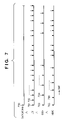
- FIG. 7 is a timing chart of display update processing of animation display
- FIG. 8 shows a construction of schedule data for animation processing according to the embodiment of the present invention.
- FIG. 9 is a flowchart showing animation processing steps
- FIG. 10 is a diagram showing operation sequence of the game machine according to the embodiment of the present invention.
- FIG. 11 shows a sheet of stickers printed by the game machine according to the embodiment of the present invention.
- FIG. 12 shows a construction of senjafuda (to be described later) sticker
- FIG. 13 is a flowchart showing sticker printing processing steps
- FIG. 14 is a flowchart showing detailed processing of step S 104 in FIG. 13 .
- FIG. 1 is a perspective view showing an external appearance of an arcade game machine according to an embodiment of the present invention.
- a guide is given by screen display or voice. According to the guide, a user selects and inputs a number of characters. The characters and illustrations are combined, and an original sticker in the form of senjafuda is generated and printed. Senjafuda is a Japanese amulet card presented to a shrine to be pasted on the ceiling or pillar of the shrine.
- the game machine comprises: a coin shooter for sorting inserted coins, which includes a coin slot 1 and return-coin outlet 2 ; monitor 3 for displaying a demonstration screen and guide screen; touch panel 4 , layered over the monitor 3 , to serve as a user input interface; speaker 5 for outputting sound effects or voice; presentation board 6 for explaining the game machine and operation; and outlet 7 for outputting a sticker.
- the game machine internally comprises a power source, motherboard incorporating a CPU for controlling the entire machine, printer for printing a sticker, lighting for the presentation board or the like, and CD-ROM drive serving as an external storage device.
- FIG. 2 is a block diagram showing a control structure of the game machine shown in FIG. 1 .
- the game machine is constructed such that the entire machine is controlled by a motherboard 10 incorporating a CPU, to which electric power is supplied by a power source 11 .
- a CD-ROM drive 12 is connected to the mother board 10 through an E-IDE (Enhanced Integrated Drive Electronics) port.
- the monitor 3 is connected to the mother board 10 through an RGB output terminal.
- the touch panel 4 is connected to the motherboard 10 through a COM interface.
- a printer 13 is connected to the motherboard 10 through an LPT interface.
- the speaker 5 is connected to the motherboard 10 through a Line Out interface.
- a coin controller 14 inclusive of a coin shooter 141 and counter 142 , and lighting device 15 are connected to an I/O terminal of the motherboard 10 through a relay substrate 140 .
- the relay substrate 140 is provided as the need arises for facilitating maintenance. Further, although not described in the embodiment of the present invention, the motherboard 10 comprises a video input terminal for inputting an image picked up by a camera or the like.
- the main components of the motherboard 10 are: a power circuit 103 connected to the main switch; clock generator 102 for supplying clock signals to each unit; reset circuit 104 for outputting a reset signal; and CPU 101 for controlling the entire machine.
- a secondary cache memory 111 , main memory 113 , and chip set A 112 for the peripheral LSI are connected to the CPU bus.
- the chip set A 112 includes a memory controller and cache controller, and performs signal conversion between the CPU bus and PCI (Peripheral Component Interconnect) bus.
- PCI Peripheral Component Interconnect
- the main memory 113 is divided into a normal space 113 A, where programs (including OS) and execution data are stored, and a RAM disk 113 B serving as a virtual disk drive, as will be described later.
- the PCI bus is controlled by the chip set A 112 and serves as an external bus directly connected to the CPU 101 .
- Components connected to the PCI bus are: a graphic controller 121 ; chip set B 122 ; video capture 123 capturing image data by a camera or the like which is optionally connected; and PISA bus slot 124 commonly used by the PCI bus and ISA bus.
- the graphic controller 121 comprises VRAM where image display data is stored, and includes an RGB output terminal to be connected to the monitor 3 and an output terminal to be connected to a liquid crystal display.
- the chip set B 122 serves as a bridge between the PCI bus and ISA (Industry Standard Architecture) bus, controls an E-IDE port and USB port which are connected to an external storage device such as the CD-ROM drive 12 , and controls interruption or direct memory access (DMA).
- ISA Industry Standard Architecture
- the ISA bus is controlled by the chip set B 122 .
- Components connected to the ISA bus are: a super I/O 131 ; sound controller 132 having a sound source to be outputted to the speaker 5 and a MIDI interface; basic input output system (BIOS) 133 ; parallel I/O 134 connected to the coin controller 14 and lighting device 15 ; and SIMM-ISA conversion connector 135 connected to the ISA bus through an SIMM socket.
- the super I/O 131 has a COM terminal to be connected to the touch panel 4 serving as a coordinate input apparatus, LPT terminal to be connected to the printer 13 , and interfaces for a keyboard, mouse, and floppy disk.
- the game machine is constructed based upon the construction of the PC-AT compatible devices developed by IBM.
- the CD-ROM drive 12 serves as an external storage device in the game machine, generally used magnetic-recording-type hard disk is not included in the game machine. However, hard disk may be provided to store other data.
- step S 42 When a main switch is turned on in step S 41 , in step S 42 , an electric power is supplied to each unit by the power circuit 103 , then the clock generator 102 is started for generating clock signals, and a reset signal is inputted from the reset circuit 104 to each unit of the machine.
- step S 43 the BIOS 133 is started. Since the BIOS 133 is set so as to prioritize the start-up of the CD-ROM drive 12 , the CD-ROM drive 12 is first started, and then data is read out of a start-up CD-ROM set in the CD-ROM drive 12 and developed in the main memory 113 .
- FIG. 5 is a conceptual view of data recorded in the start-up CD-ROM.
- the start-up CD-ROM 50 includes three types of data: data (system file) 51 for a disk operating system (DOS) such as MS-DOS (registered trademark of Microsoft) serving as a primary OS; data 52 for Windows (registered trademark of Microsoft) serving as a secondary OS; and data 53 for an application program of the game machine.
- DOS disk operating system
- MS-DOS registered trademark of Microsoft
- Windows registered trademark of Microsoft
- the Windows data 52 recorded in the start-up CD-ROM 50 is not the data for installation which is stored in the generally known set-up disk, but is an executable file-form data generated by installation processing.
- the file-form Windows data 52 necessary for the application program of the game machine the amount of data recorded in the start-up CD-ROM 50 can be reduced and manufacturing of the start-up CD-ROM can be facilitated. Also, the time lag between the start-up of the machine and start-up of the application program can be reduced.
- step S 44 in FIG. 4 the system data 51 for DOS serving as the primary OS, which is recorded in the boot area of the CD-ROM, is first read from the start-up CD-ROM 50 to the main memory 113 .
- MS-DOS is automatically started.
- step S 45 the MS-DOS generates the RAM disk 113 B which serves as a virtual disk drive in the main memory 113 .
- step S 46 a part of Windows, serving as the secondary OS, is copied from the start-up CD-ROM 50 to the RAM disk 113 B by the DOS.
- files to be copied in the RAM disk 113 B are files that are rewritten (updated) by the secondary OS during operation of the application program, i.e., swap areas, disk cache, registry files and so forth.
- a start-up file (win.comm or the like) necessary for starting the secondary OS (in this case, Windows) is also copied.
- files that are not rewritten but frequently accessed during operation of the application program are also copied in the RAM disk 113 B.
- the number of times of accessing the CD-ROM during operation of the application program can be reduced. Accordingly, errors caused by mechanical accessing operation of the CD-ROM can be reduced, and the time required for reading data can considerably be reduced.
- step S 47 the start-up file copied in the RAM disk 113 B is executed.
- Windows serving as the secondary OS is started by using the RAM disk 113 B and start-up CD-ROM 50 .
- step S 48 the data 53 for the application program is read and the application program is started by using the start-up CD-ROM 50 , and operation of the game machine begins.
- files of the application program and Windows are read from the start-up CD-ROM 50 as needed during operation of the game machine.
- the swap area, disk cache, registry files and so on, which are copied in the RAM disk 113 B, are rewritten during the operation of the application program.
- the game machine can be stably started because, even when Windows is used as an operating system, the game machine does not access a secondary storage having a mechanical access mechanism, e.g., readable/writable magnetic-recording-type hard disk or the like.
- the game machine is constructed such that, at the time of start-up, data is stably read from read-only memory, i.e., CD-ROM, and files subjected to writing operation are stored in the electrically volatile memory, i.e., RAM disk, generated in the main memory.
- the magnetic-recording-type hard disk is to be used for reading operation only, hard disk may be provided. In other words, the physical shape of the storage is not an issue here.
- the game machine employs CD-ROM as a primary storage medium for storing three types of data: primary OS data, secondary OS data, and data for the application program of the game machine.
- a primary storage medium other than CD-ROM may be used, for instance, DVD-RAM, ROM or the like may be used. In some cases, hard disk may be used.
- files that are rewritten (updated) during operation of the application program are copied in the RAM disk so that writing operation is performed in the RAM disk.
- other media or construction may be employed.
- UNIX which is a character based user interface (CUI) similar to MS-DOS may be used.
- CCI character based user interface
- GUI X Window system
- the environment where the application program is operable must have the following characteristic. More specifically, an OS which supports operation of the application program must execute writing operation in a high-speed volatile storage medium, e.g., RAM drive or the like, in accordance with a request from the OS or application program.
- a high-speed volatile storage medium e.g., RAM drive or the like
- the processing of the application program is roughly divided into two processes: one is sticker printing processing performed when a coin is inserted, and the other is animation display processing performed during non-operation state, i.e., during a period from sticker output to the next coin insertion.
- Animation display processing is first described.
- animation is generally realized by generating images frame by frame and sequentially displaying the frame images.
- the generated amount of data is extremely large.
- processors are capable of considerably fast processing and capable of decoding and displaying compressed moving images by using software, such processors are expensive and generation of moving images is time consuming.
- animation is a collection of relatively small image parts.
- display update timing independently controlling update timing of displaying each image part
- FIGS. 6A and 6B show a part of animation image used in the present embodiment. Shown in FIG. 6A is a shishimai (ritual dancer with a lion's mask) dancing and approaching forward, and shown in FIG. 6B is a shishimai leaving backward.
- shishimai temporary dancer with a lion's mask
- This image can be roughly divided into the following parts (image parts) that constitute the animation: an image 600 of a torii (shrine archway) on the background, image 601 of the shishimai's leg, image 602 of the shishimai's body, and image 603 of the shishimai's head.
- image parts Various patterns of these image parts are prepared and stored in the main memory 113 .
- the head and leg parts (in some cases, body part as well) are prepared for the case of facing forward and backward.
- plural patterns of the body, head, and leg parts facing one direction are prepared.
- background image 600 ⁇ leg image 601 ⁇ body image 602 ⁇ head image 603
- background image 600 ⁇ head image 603 ⁇ leg image 601 ⁇ body image 602
- the embodiment of the present invention manages the less-than signs ( ⁇ ) in layers.
- reproduction processings of respective layers are performed in parallel (note that reproduction processing includes displaying animation on the screen and playing audio data).
- the attribute data is stored in the memory 113 in the form of a table.
- FIG. 7 is a timing chart of display update processing of each layer for FIG. 6A .
- the background image 600 is in the lowest layer, i.e., an image in the bottom of the layers. Display processing of the background image 600 is executed at timing 700 , and will not be executed on the layer until a series of animation ends.
- Display update processing for the leg, body and body parts on the upper layers is performed by rewriting respective images on the layer at timing 701 , 702 , . . . , or 703 , 704 , . . . , or 705 , 706 . . . , as shown in FIG. 7 (execution of display update tasks).
- the display update processing is performed according to the attribute data written respectively for each layer and stored in the main memory 113 .
- leg image in order to express various movement of leg, a number of types of leg image files are prepared. Similarly, a number of types of head image files, e.g., a head image with an open mouse and a head image with a closed mouse and so on, are prepared. Note that the number of files prepared is not equal to the number of times of display update processing shown in FIG. 7 . By having attribute data described below, various movement of an image can be expressed.
- attribute data stored as a table in a predetermined area of the main memory includes: duration from the start of one display processing to the start of the next display processing, display coordinate data, image magnification (reduction) rate, and rotational angle.
- attribute data includes time data only. Attribute data regarding time and coordinates should be self-explanatory in the above description. Attribute data regarding an image magnification rate and rotational angle is briefly described below. In order to show the image in FIG. 6A as if the shishimai is approaching forward from the torii (shrine archway), the image size is gradually changed from small to large. The magnification rate is provided as attribute data to realize this movement. In the image shown in FIG.
- the image of shishimai moving away can be similarly realized.
- the rotational angle is provided as attribute data in order to give variation to the movement. Variation can be given to the movement if a large number of images are prepared. However, by providing a rotational angle to the image (particularly, to the head image), various expression can be realized with a small number of images. Note that the inventors of the present invention have confirmed that sufficient animation effect can be attained with about 1 to 0.5 seconds of minimum display update timing, although this depends upon the processor's performance.
- FIG. 8 shows a construction of schedule data in each layer, which realizes the display update timing shown in FIG. 7 .
- the schedule data referred to by reference numerals 800 to 806 are executed respectively at the timing 700 to 706 in FIG. 7 .
- layers controlled by the embodiment of the present invention are not limited to image files, but audio files are also controlled. Since audio files do not have a concept of one data being on top of the other data, audio files only includes time data indicative of duration from the start of one display processing to the start of the next display processing (data for volume setting or the like may be included in the audio files).
- Attribute data may also include data regarding a filter.
- filter data a filter for calculating an average value of a predetermined area (variable size) may be used. Having a filter has the following effect. For instance, by showing the image of shishimai with the head being focused and the body and leg being out of focus, shishimai can be expressed in perspective. The level of focus may be set for each layer.
- schedule data does not always need to have a file name. For instance, assume that execution of an audio file “onsei.wav” is to be started 10 seconds after starting a series of animation. This means that the audio file is not executed for 10 seconds at the beginning.
- the schedule data 810 in FIG. 8 has a file name “Null” (used as a reserved word) for not executing the audio file, and the attribute data has “10 seconds”. This explanation also applies to an image file.
- processing of each layer is started at the timing indicated by arrows in FIG. 7 .
- display processing and audio output processing are performed at respective timing, and no particular processing is performed until the next update timing comes.
- Other processing is performed by the OS.
- the application program constructs a synthesized image at a certain timing and displays the synthesized image.
- the display timing in this case is determined by the display update timing of one of the layers.
- display images need not be generated frame by frame. Instead, animation display can be realized by deciding a schedule of processing execution timing for each layer. In addition, since the processor's load can be considerably reduced, sufficient quality of animation reproduction can be realized without requiring an expensive high-speed processor.
- FIG. 8 shows the schedule of realizing FIG. 6A .
- the attribute data is changed so as to read body image data in the layer 3 , head image data in the layer 2 , leg image data in the layer 1 , and background image data in the layer 0 (images read in the layers 2 and 1 may be reversed).
- step S 91 animation data (file having a structure shown in FIG. 8 ), which has the file name designated by the upper processing, is read in the main memory 113 .
- step S 92 the number of layers to be constructed is determined and animation end time is determined based on the read schedule.
- step S 93 a processing-start timing schedule for each layer is generated and stored in the memory. For instance, in the case of FIG. 7 , in order to execute processing for 700 , 701 , 703 and 705 at the time of start-up and smoothly execute processing for 702 after the lapse of predetermined time (time set by the attribute data in 801 in FIG. 8 ), the start-up timing and tasks to be executed are arranged in a proper time sequence. This is due to the fact that the timing schedule is defined as attribute data in the memory.
- step S 94 it is determined whether or not any processing-start timing has arrived according to the data generated in step S 93 . If YES in step S 94 , the control proceeds to step S 95 . Then, data required for the tasks (one or plural) to be started is transferred to the VRAM of the graphic controller 121 , and the processing is executed. Then, the control returns to step S 94 . Note that since plural layers cannot be truly simultaneously processed, data is written in the VRAM of the graphic controller 121 from the lower layer first. In the upper layer, an image portion, which overlaps with the image to be written by the upper layer, is saved. However, if the OS is capable of equivalent processing, this processing is not necessary.
- step S 94 the control proceeds to step S 96 where it is determined whether or not the processing for the animation data read in step S 91 (designated by the upper processing) is completed. If NO in step S 96 , the control returns to step S 94 , but if YES, the processing ends.
- Animation is not limited to one, but plural types of animation may be provided. In the upper processing, reproduction of plural animation is managed. One animation may be an image of shishimai approaching forward, and the other animation may be an image of shishimai leaving backward. Alternatively, completely different animation may be provided.
- one animation may include an image of shishimai approaching forward and then leaving backward. This can be realized easily.
- the image parts, constructing animation are stored in CD-ROM and the data is read therefrom.
- the image part data may temporarily be copied in the RAM disk as mentioned above. Then, the image data is written for each layer in a predetermined area of the memory 113 , and written in the VRAM of the graphic controller 121 according to attribute data.
- a sticker outputted (printed) by the game machine (sticker printing apparatus) according to the embodiment of the present invention has a form of senjafuda (hereinafter referred to as a senjafuda sticker).
- a senjafuda sticker An example is shown in FIG. 11 .
- a sheet of senjafuda comprises eight pieces of senjafuda stickers, so that a user can peel off the sticker one by one and stick it on a desired object.
- a senjafuda sticker consists of the following image parts.
- a senjafuda sticker includes: jimon as a background of the sticker, kashira as a header of the sticker, body of the senjafuda, and sashifuda as an insertion.
- Plural design patterns are prepared for the jimon (background), kashira (header), body, and sashifuda (insertion) and stored in the main memory 113 , then displayed in the monitor 3 .
- a user of the game machine selects a desired design pattern by coordinate input on the touch panel 4 .
- plural character strings are prepared for the jimon (background), kashira (header), body, and sashifuda (insertion). The user can either select a desired character string from the prepared character strings, or input desired characters.
- a user sequentially sets image parts in the above-described manner, and instructs printing of a sticker. According to the set contents, printing is performed, and a sheet of stickers as shown in FIG. 11 is printed.
- step S 101 contents of various setting are initialized prior to printing process.
- the initializing processing includes resetting of variables, which represent setting contents of the jimon, kashira, body, and sashifuda.
- step S 102 setting processing for jimon (background) (setting processing for the lowest layer image) is performed.
- jimon setting processing plural predetermined jimon patterns are written in the VRAM of the graphic controller 121 and displayed on the monitor 3 .
- a desired jimon pattern is selected by the user who designates a coordinate position on the touch panel 4 .
- information related to the selected jimon pattern is stored in a predetermined area of the main memory 113 as a variable for jimon, which has been initialized in step S 101 .
- step S 103 it is determined whether or not the setting for jimon is satisfactory to the user by using the touch panel 4 .
- the control returns to step S 102 by the CPU.
- the jimon pattern previously selected by the user is temporarily stored as a bit image in the VRAM of the graphic controller 121 and displayed (enabled by the contents of the variable), so as to allow the user easy selection.
- step S 104 for performing setting of kashira (header) in the main memory 113 (setting processing for the second lowest layer image).
- the design and the character string to be incorporated in the design (header “ ” in FIG. 11 ) are set.
- a design mainly, selection of a character font and color
- plural designs are displayed and the user selects one by using the touch panel 4 or inputting a command, as similar to selection of jimon (background).
- a character string is selected in the similar manner. The user selects one from character strings prepared in advance.
- a touch area is provided on the display screen so as to enable the user inputting user-original character strings.
- a keyboard capable of kana-kanji character conversion (unique to Japanese characters) is displayed, allowing the user to input desired character strings in a predetermined area of the memory 113 .
- the set design and character string are stored in a predetermined area of the main memory 113 as a variable for kashira (header). Therefore, the contents once set can be changed.
- step S 105 the control branches in accordance with the designation from the touch panel 4 . More specifically, if the user designates to perform setting of kashira again (NG in step S 105 ), the control returns to step S 104 for performing the setting processing again.
- the contents previously set are stored as default data in a predetermined area of the main memory 113 . By virtue of this, the user can see the previous setting. In a case where the user has made setting by kana-kanji character conversion and wishes to change the design only but to keep the selected character string, the user does not need to input the character string again, but only needs to depress an OK button.
- step S 109 the control returns from step S 109 to step S 106 for performing the setting of body again. Since the contents of previous setting is displayed, the user can change a desired part only, and if no other change is to be made, the user depresses a confirm button such as OK button on the touch panel.
- an image of the senjafuda sticker constructed up to this point is written in the VRAM of the graphic controller 121 according to the setting contents of each layer, and displayed on a predetermined position of the monitor 3 .
- step S 110 for option setting.
- whether to print/not print the sashifuda (insertion) is set. This option setting is performed because, in some cases, the character string in the body is hidden by the sashifuda (insertion “ ”) as shown in FIG. 11 . If the user designates not to print the sashifuda, the set sashifuda is not printed in all the sticker body. If the user designates to print the sashifuda, half of the stickers (four stickers) is printed with the sashifuda and the other half of the stickers is printed without sashifuda as shown in FIG. 11 .
- step S 104 the setting processing of kashira (header) (step S 104 ) is described further in detail. With respect to the setting processing of body and sashifuda (steps S 106 and S 108 ), detailed description will not be provided because the same processing as that for kashira is performed.
- FIG. 14 is a flowchart showing detailed steps of setting processing of kashira (header) for a senjafuda sticker according to the present embodiment.
- step S 201 a list of kashira (header) designs stored in the CD-ROM is displayed on the monitor 3 , allowing the user to select one on the display screen.
- an OK button and return button or the like are also displayed along with the designs.
- step S 203 a list of character strings (character strings prepared in advance) to be used as a kashira (header) is displayed on the monitor 3 , allowing the user to select one.
- an OK button, key input instruction button, cancel button and so on are also displayed.
- step S 205 data designating the selected design and character string is written as a variable representing kashira (header) and stored.
- step S 206 a character pattern image is generated with a dot image according to the font data based on the set character string (character code string) and the set design. Then, the generated image data is written as a corresponding layer in a predetermined area of the VRAM of the graphic controller 121 , and the dot image is displayed in the predetermined area of the monitor 3 . By this, an image of the senjafuda sticker constructed up to this point is displayed for the user. Then, the processing ends.
- step S 204 if the user does not select a character string from the list displayed on the monitor 3 , the control proceeds to step S 208 .
- step S 208 it is determined whether or not the user wishes to input a new user-original character string. If YES in step S 208 , the displayed list of character strings is erased, and a keyboard is displayed on the monitor 3 . By touching a displayed key, kana-kanji character conversion is performed. Kana-kanji character conversion is realized by employing a program included as a standard in Windows. Since a keyboard is not provided physically, a driver program for touch keyboard is prepared to simulate a physical keyboard. Data is transferred from the driver program to the kana-kanji conversion processor. In order to improve operability and achieve user-friendly and accurate kana-kanji character conversion, character conversion is performed word by word.
- the sashifuda (insertion) is not only superimposed upon the character image on the lower layer, but is arranged at an angle.
- the application program obtains (generates) image data based on the contents of the setting and stores the data independently in the memory, unlike general word processors which let an OS perform the display processing of a character string and design set in each layer. Since image data for each layer is independently stored in the memory, printing the sashifuda at an angle can easily be achieved by rotation processing (rotating sashifuda by a given angle). As a result, stickers with sashifuda shown in FIG. 11 are printed.
- step S 112 printing processing is performed in step S 112 .
- resolution of a display screen of a game machine is about 75 dpi.
- the monitor 3 in the present embodiment has resolution of 75 dpi.
- the printer 13 in the present embodiment employs an ink-jet type printer applying heat energy, which is capable of printing sufficiently high quality images, e.g., 1400 dpi.
- the printer 13 has a resolution of 600 dpi for each color component.
- the synthesized image of the sheet of stickers which is generated by the above-described setting operation and displayed on the screen for user's confirmation, has a size twice as large as the actually printing image.
- a variable which is allocated for each layer in the main memory and contains setting contents is referred, and an image to be printed is generated for each layer in the main memory.
- a jimon (background) image two types of images, one to be displayed and the other to be printed, are already prepared and stored in advance in the CD-ROM. From this CD-ROM, a variable representing the jimon image to be printed is read and stored in the main memory. Then, a print image for kashira (header), which is positioned logically higher than the jimon (background), is generated according to the character code string, font and font size which have been set in the variable for kashira.
- the generated print image data for kashira is written on top of the print image data for jimon.
- a print image for body which is the layer higher than the kashira layer, is generated according to the character code string, font, and font size which have been set in the variable for the body.
- the generated print image data for body is written to be synthesized with the already-generated image (synthesized image of jimon and kashira).
- eight stickers of the above synthesized image is printed.
- the above synthesized image generated so far (synthesized image of jimon, kashira and body) is generated (copied) in another predetermined area of the main memory. Then, a print image for sashifuda, represented by a variable, is generated. The generated print image for sashifuda is rotated by a predetermined angle, and synthesized with the copied image in the main memory.
- two types of synthesized image data one with sashifuda and the other without sashifuda, are generated. Based on these image data, four stickers are generated for each image (see FIG. 11 ).
- the image for printing is generated only if the user designates to proceed from the option setting. This is because, as apparent from the description of hardware of the game machine of the embodiment, the machine does not have a hard disk for generating a temporary file, and thus the machine must efficiently utilize the limited main memory and RAM disk (disk drive generated logically in the file system). More specifically, if an image for printing is generated in the setting of each layer, a large amount of memory shall be consumed.
- the image data ultimately necessary is not the image data for each layer, but is the synthesized image data to be printed.
- the memory necessary for the synthesized image data is small, so that data generation can be efficiently performed. Note in a case where the user selects to print sashifuda (insertion) in the option setting, two types of synthesized image data (with sashifuda and without sashifuda) are generated in the above description.
- the synthesized image data without sashifuda and image data of sashifuda may be independently stored in the main memory, and printing may be performed while controlling, in real time, whether to synthesize or not synthesize the sashifuda image. By this, the necessary memory capacity is further reduced.
- the animation display is executed during a period from sticker output to the next coin insertion.
- the animation may be displayed while stickers are being printed, by using an available area of the monitor 3 .
- a machine displaying animation only may be provided.
- the present invention is not limited to the aforementioned game machine, but is widely applicable to machines which execute particular applications, e.g., vending machines or industrial machines or the like.
- a number of user-original character strings can be inputted, and varieties of stickers can be printed by superimposing the inputted character strings.
Abstract
Description
-
- Since an application program can be developed by using an application programming interface of a generally used OS having an established environment, the time and cost required for developing an application program can considerably be reduced.
- The hardware, except particular I/O units which are different for each application program, can be commonly used for all game machines. Accordingly, reliability of the entire game machines can be increased with the reliable common hardware. Moreover, the cost of the hardware can be reduced by mass production.
- When a part of an application program is to be corrected or modified, conventionally ROM must be changed. This required an expert maintenance worker. However, in the game machine of the present embodiment, only the start-up CD-ROM needs to be changed (exchanged). This can be done by any personnel of a game center or the like who does not have expertise of personal computers.
- Although a general-purpose OS, e.g., Windows, is employed, the game machine can be started or shut down stably by simply turning on/off the main switch.
Claims (10)
Applications Claiming Priority (2)
| Application Number | Priority Date | Filing Date | Title |
|---|---|---|---|
| JP11089717A JP2000285258A (en) | 1999-03-30 | 1999-03-30 | Animation display device, game device, control method, display device, and storage medium |
| JP11089716A JP2000280561A (en) | 1999-03-30 | 1999-03-30 | Seal issuing unit and control method thereof, printer and memory medium |
Publications (1)
| Publication Number | Publication Date |
|---|---|
| US7472910B1 true US7472910B1 (en) | 2009-01-06 |
Family
ID=40174892
Family Applications (1)
| Application Number | Title | Priority Date | Filing Date |
|---|---|---|---|
| US09/537,288 Expired - Fee Related US7472910B1 (en) | 1999-03-30 | 2000-03-29 | Animation display apparatus, arcade game machine, control method and apparatus thereof, and storage medium |
Country Status (1)
| Country | Link |
|---|---|
| US (1) | US7472910B1 (en) |
Cited By (32)
| Publication number | Priority date | Publication date | Assignee | Title |
|---|---|---|---|---|
| US20070150364A1 (en) * | 2005-12-22 | 2007-06-28 | Andrew Monaghan | Self-service terminal |
| US20100210353A1 (en) * | 2007-10-17 | 2010-08-19 | Gagner Mark B | Presenting wagering game content |
| US20100280657A1 (en) * | 2009-05-01 | 2010-11-04 | Henry Tyson | Character nameplate kiosk and method for making a personalized nameplate |
| US20110209137A1 (en) * | 2008-10-27 | 2011-08-25 | Lars-Ake Berg | Label printer api using program scripting language |
| US20120137314A1 (en) * | 2009-06-08 | 2012-05-31 | Staffan Gribel | System and method for injecting run-time programming code in a printing device |
| US20140148946A1 (en) * | 2010-11-08 | 2014-05-29 | Junfang Zhang | Sales kiosk |
| US9672691B2 (en) | 2010-08-06 | 2017-06-06 | Bally Gaming, Inc. | Controlling wagering game system browser areas |
| US9713763B2 (en) | 2007-09-30 | 2017-07-25 | Bally Gaming, Inc. | Distributing information in a wagering game system |
| US20170345460A1 (en) * | 2014-04-10 | 2017-11-30 | JBF Interlude 2009 LTD | Systems and methods for creating linear video from branched video |
| US10418066B2 (en) | 2013-03-15 | 2019-09-17 | JBF Interlude 2009 LTD | System and method for synchronization of selectably presentable media streams |
| US10460765B2 (en) | 2015-08-26 | 2019-10-29 | JBF Interlude 2009 LTD | Systems and methods for adaptive and responsive video |
| US10474334B2 (en) | 2012-09-19 | 2019-11-12 | JBF Interlude 2009 LTD | Progress bar for branched videos |
| US10582265B2 (en) | 2015-04-30 | 2020-03-03 | JBF Interlude 2009 LTD | Systems and methods for nonlinear video playback using linear real-time video players |
| US10692540B2 (en) | 2014-10-08 | 2020-06-23 | JBF Interlude 2009 LTD | Systems and methods for dynamic video bookmarking |
| US10856049B2 (en) | 2018-01-05 | 2020-12-01 | Jbf Interlude 2009 Ltd. | Dynamic library display for interactive videos |
| US11050809B2 (en) | 2016-12-30 | 2021-06-29 | JBF Interlude 2009 LTD | Systems and methods for dynamic weighting of branched video paths |
| US11128853B2 (en) | 2015-12-22 | 2021-09-21 | JBF Interlude 2009 LTD | Seamless transitions in large-scale video |
| US11164548B2 (en) | 2015-12-22 | 2021-11-02 | JBF Interlude 2009 LTD | Intelligent buffering of large-scale video |
| US11176723B2 (en) | 2019-09-30 | 2021-11-16 | Snap Inc. | Automated dance animation |
| US11222455B2 (en) * | 2019-09-30 | 2022-01-11 | Snap Inc. | Management of pseudorandom animation system |
| US11232458B2 (en) | 2010-02-17 | 2022-01-25 | JBF Interlude 2009 LTD | System and method for data mining within interactive multimedia |
| US11245961B2 (en) | 2020-02-18 | 2022-02-08 | JBF Interlude 2009 LTD | System and methods for detecting anomalous activities for interactive videos |
| US11282253B2 (en) | 2019-09-30 | 2022-03-22 | Snap Inc. | Matching audio to a state-space model for pseudorandom animation |
| US11314936B2 (en) | 2009-05-12 | 2022-04-26 | JBF Interlude 2009 LTD | System and method for assembling a recorded composition |
| US11348297B2 (en) | 2019-09-30 | 2022-05-31 | Snap Inc. | State-space system for pseudorandom animation |
| US11412276B2 (en) | 2014-10-10 | 2022-08-09 | JBF Interlude 2009 LTD | Systems and methods for parallel track transitions |
| US11490047B2 (en) | 2019-10-02 | 2022-11-01 | JBF Interlude 2009 LTD | Systems and methods for dynamically adjusting video aspect ratios |
| US11601721B2 (en) | 2018-06-04 | 2023-03-07 | JBF Interlude 2009 LTD | Interactive video dynamic adaptation and user profiling |
| US11816773B2 (en) | 2020-09-30 | 2023-11-14 | Snap Inc. | Music reactive animation of human characters |
| US11856271B2 (en) | 2016-04-12 | 2023-12-26 | JBF Interlude 2009 LTD | Symbiotic interactive video |
| US11882337B2 (en) | 2021-05-28 | 2024-01-23 | JBF Interlude 2009 LTD | Automated platform for generating interactive videos |
| US11934477B2 (en) | 2021-09-24 | 2024-03-19 | JBF Interlude 2009 LTD | Video player integration within websites |
Citations (31)
| Publication number | Priority date | Publication date | Assignee | Title |
|---|---|---|---|---|
| US4954818A (en) * | 1985-10-18 | 1990-09-04 | Hitachi, Ltd. | Multi-window display control system |
| US5384912A (en) * | 1987-10-30 | 1995-01-24 | New Microtime Inc. | Real time video image processing system |
| US5405152A (en) * | 1993-06-08 | 1995-04-11 | The Walt Disney Company | Method and apparatus for an interactive video game with physical feedback |
| JPH07334701A (en) * | 1994-06-14 | 1995-12-22 | Ieroo Shiyaaku:Kk | Animation image compositing device |
| US5478120A (en) * | 1992-07-31 | 1995-12-26 | D'andrea; Deborah B. | Method of making a publication and product produced thereby |
| US5487010A (en) * | 1993-06-25 | 1996-01-23 | B.M.D., Inc. | Bumper sticker printing machine |
| US5494445A (en) * | 1989-12-07 | 1996-02-27 | Yoshi Sekiguchi | Process and display with moveable images |
| US5577179A (en) * | 1992-02-25 | 1996-11-19 | Imageware Software, Inc. | Image editing system |
| US5615123A (en) * | 1991-04-02 | 1997-03-25 | Creatacard, Inc. | System for creating and producing custom card products |
| US5623581A (en) * | 1996-01-22 | 1997-04-22 | Apbi Interactive Kiosk Systems | Direct view interactive photo kiosk and image forming process for same |
| US5695346A (en) * | 1989-12-07 | 1997-12-09 | Yoshi Sekiguchi | Process and display with moveable images |
| JPH1055489A (en) * | 1996-08-09 | 1998-02-24 | Masaharu Ichihara | Automatic producing device and vending machine of seal and sticker |
| US5897220A (en) * | 1996-08-30 | 1999-04-27 | American Alpha Inc. | Automatic photograph booth for forming sketches |
| US5913019A (en) * | 1996-01-22 | 1999-06-15 | Foto Fantasy, Inc. | Direct view interactive photo kiosk and composite image forming process for same |
| US5920687A (en) * | 1993-05-10 | 1999-07-06 | Apple Computer, Inc. | Z-buffer storage based on opacity and depth using pointers |
| US5930810A (en) * | 1995-08-09 | 1999-07-27 | Taylor Corporation | Printing system with pre-defined user modifiable forms and local and remote printing |
| US6008820A (en) * | 1995-08-04 | 1999-12-28 | Microsoft Corporation | Processor for controlling the display of rendered image layers and method for controlling same |
| US6065969A (en) * | 1998-08-10 | 2000-05-23 | Mattel, Inc. | Computer game for designing and printing nail coverings |
| US6071671A (en) * | 1996-12-05 | 2000-06-06 | Omd Devices Llc | Fluorescent optical memory |
| US6085195A (en) * | 1998-06-02 | 2000-07-04 | Xstasis, Llc | Internet photo booth |
| US6116906A (en) * | 1998-08-18 | 2000-09-12 | Mattel, Inc. | Computer method for producing stickers for toy vehicles |
| US6121960A (en) * | 1996-08-28 | 2000-09-19 | Via, Inc. | Touch screen systems and methods |
| US6310627B1 (en) * | 1998-01-20 | 2001-10-30 | Toyo Boseki Kabushiki Kaisha | Method and system for generating a stereoscopic image of a garment |
| US20020018070A1 (en) * | 1996-09-18 | 2002-02-14 | Jaron Lanier | Video superposition system and method |
| US6353772B1 (en) * | 1997-07-15 | 2002-03-05 | Silverbrook Research Pty Ltd | Vending machine for the production of customized photos and artcards including a set of instructions for a manipulation of an image |
| US6369908B1 (en) * | 1999-03-31 | 2002-04-09 | Paul J. Frey | Photo kiosk for electronically creating, storing and distributing images, audio, and textual messages |
| US6452583B1 (en) * | 1997-07-18 | 2002-09-17 | Ngk Insulators, Ltd. | Display-driving device and display-driving method |
| US6470232B2 (en) * | 2001-01-18 | 2002-10-22 | Hewlett-Packard Company | Customized wrapping paper kiosk |
| US6571211B1 (en) * | 1997-11-21 | 2003-05-27 | Dictaphone Corporation | Voice file header data in portable digital audio recorder |
| US6684188B1 (en) * | 1996-02-02 | 2004-01-27 | Geoffrey C Mitchell | Method for production of medical records and other technical documents |
| US6839755B1 (en) * | 1998-09-30 | 2005-01-04 | Hewlett-Packard Development Company, L.P. | Network peripheral server discovery method |
-
2000
- 2000-03-29 US US09/537,288 patent/US7472910B1/en not_active Expired - Fee Related
Patent Citations (31)
| Publication number | Priority date | Publication date | Assignee | Title |
|---|---|---|---|---|
| US4954818A (en) * | 1985-10-18 | 1990-09-04 | Hitachi, Ltd. | Multi-window display control system |
| US5384912A (en) * | 1987-10-30 | 1995-01-24 | New Microtime Inc. | Real time video image processing system |
| US5695346A (en) * | 1989-12-07 | 1997-12-09 | Yoshi Sekiguchi | Process and display with moveable images |
| US5494445A (en) * | 1989-12-07 | 1996-02-27 | Yoshi Sekiguchi | Process and display with moveable images |
| US5615123A (en) * | 1991-04-02 | 1997-03-25 | Creatacard, Inc. | System for creating and producing custom card products |
| US5577179A (en) * | 1992-02-25 | 1996-11-19 | Imageware Software, Inc. | Image editing system |
| US5478120A (en) * | 1992-07-31 | 1995-12-26 | D'andrea; Deborah B. | Method of making a publication and product produced thereby |
| US5920687A (en) * | 1993-05-10 | 1999-07-06 | Apple Computer, Inc. | Z-buffer storage based on opacity and depth using pointers |
| US5405152A (en) * | 1993-06-08 | 1995-04-11 | The Walt Disney Company | Method and apparatus for an interactive video game with physical feedback |
| US5487010A (en) * | 1993-06-25 | 1996-01-23 | B.M.D., Inc. | Bumper sticker printing machine |
| JPH07334701A (en) * | 1994-06-14 | 1995-12-22 | Ieroo Shiyaaku:Kk | Animation image compositing device |
| US6008820A (en) * | 1995-08-04 | 1999-12-28 | Microsoft Corporation | Processor for controlling the display of rendered image layers and method for controlling same |
| US5930810A (en) * | 1995-08-09 | 1999-07-27 | Taylor Corporation | Printing system with pre-defined user modifiable forms and local and remote printing |
| US5623581A (en) * | 1996-01-22 | 1997-04-22 | Apbi Interactive Kiosk Systems | Direct view interactive photo kiosk and image forming process for same |
| US5913019A (en) * | 1996-01-22 | 1999-06-15 | Foto Fantasy, Inc. | Direct view interactive photo kiosk and composite image forming process for same |
| US6684188B1 (en) * | 1996-02-02 | 2004-01-27 | Geoffrey C Mitchell | Method for production of medical records and other technical documents |
| JPH1055489A (en) * | 1996-08-09 | 1998-02-24 | Masaharu Ichihara | Automatic producing device and vending machine of seal and sticker |
| US6121960A (en) * | 1996-08-28 | 2000-09-19 | Via, Inc. | Touch screen systems and methods |
| US5897220A (en) * | 1996-08-30 | 1999-04-27 | American Alpha Inc. | Automatic photograph booth for forming sketches |
| US20020018070A1 (en) * | 1996-09-18 | 2002-02-14 | Jaron Lanier | Video superposition system and method |
| US6071671A (en) * | 1996-12-05 | 2000-06-06 | Omd Devices Llc | Fluorescent optical memory |
| US6353772B1 (en) * | 1997-07-15 | 2002-03-05 | Silverbrook Research Pty Ltd | Vending machine for the production of customized photos and artcards including a set of instructions for a manipulation of an image |
| US6452583B1 (en) * | 1997-07-18 | 2002-09-17 | Ngk Insulators, Ltd. | Display-driving device and display-driving method |
| US6571211B1 (en) * | 1997-11-21 | 2003-05-27 | Dictaphone Corporation | Voice file header data in portable digital audio recorder |
| US6310627B1 (en) * | 1998-01-20 | 2001-10-30 | Toyo Boseki Kabushiki Kaisha | Method and system for generating a stereoscopic image of a garment |
| US6085195A (en) * | 1998-06-02 | 2000-07-04 | Xstasis, Llc | Internet photo booth |
| US6065969A (en) * | 1998-08-10 | 2000-05-23 | Mattel, Inc. | Computer game for designing and printing nail coverings |
| US6116906A (en) * | 1998-08-18 | 2000-09-12 | Mattel, Inc. | Computer method for producing stickers for toy vehicles |
| US6839755B1 (en) * | 1998-09-30 | 2005-01-04 | Hewlett-Packard Development Company, L.P. | Network peripheral server discovery method |
| US6369908B1 (en) * | 1999-03-31 | 2002-04-09 | Paul J. Frey | Photo kiosk for electronically creating, storing and distributing images, audio, and textual messages |
| US6470232B2 (en) * | 2001-01-18 | 2002-10-22 | Hewlett-Packard Company | Customized wrapping paper kiosk |
Non-Patent Citations (1)
| Title |
|---|
| Internet download "welcome to the world of Senja-Cards". * |
Cited By (50)
| Publication number | Priority date | Publication date | Assignee | Title |
|---|---|---|---|---|
| US20070150364A1 (en) * | 2005-12-22 | 2007-06-28 | Andrew Monaghan | Self-service terminal |
| US10406426B2 (en) | 2007-09-30 | 2019-09-10 | Bally Gaming, Inc. | Distributing information in a wagering game system |
| US9713763B2 (en) | 2007-09-30 | 2017-07-25 | Bally Gaming, Inc. | Distributing information in a wagering game system |
| US9005011B2 (en) * | 2007-10-17 | 2015-04-14 | Wms Gaming, Inc. | Presenting wagering game content |
| US20100210353A1 (en) * | 2007-10-17 | 2010-08-19 | Gagner Mark B | Presenting wagering game content |
| US9792761B2 (en) | 2007-10-17 | 2017-10-17 | Bally Gaming, Inc. | Presenting wagering game content |
| US9870522B2 (en) * | 2008-10-27 | 2018-01-16 | Sato Holdings Kabushiki Kaisha | Label printer API using LUA program scripting language |
| US20110209137A1 (en) * | 2008-10-27 | 2011-08-25 | Lars-Ake Berg | Label printer api using program scripting language |
| US20100280657A1 (en) * | 2009-05-01 | 2010-11-04 | Henry Tyson | Character nameplate kiosk and method for making a personalized nameplate |
| US9666014B2 (en) * | 2009-05-01 | 2017-05-30 | Colorvision International, Inc. | Character nameplate kiosk and method for making a personalized nameplate |
| US11314936B2 (en) | 2009-05-12 | 2022-04-26 | JBF Interlude 2009 LTD | System and method for assembling a recorded composition |
| US20120137314A1 (en) * | 2009-06-08 | 2012-05-31 | Staffan Gribel | System and method for injecting run-time programming code in a printing device |
| US9886289B2 (en) * | 2009-06-08 | 2018-02-06 | Sato Holdings Kabushiki Kaisha | System and method for injecting run-time programming code in a printing device |
| US11232458B2 (en) | 2010-02-17 | 2022-01-25 | JBF Interlude 2009 LTD | System and method for data mining within interactive multimedia |
| US9672691B2 (en) | 2010-08-06 | 2017-06-06 | Bally Gaming, Inc. | Controlling wagering game system browser areas |
| US10186111B2 (en) | 2010-08-06 | 2019-01-22 | Bally Gaming, Inc. | Controlling wagering game system browser areas |
| US20140148946A1 (en) * | 2010-11-08 | 2014-05-29 | Junfang Zhang | Sales kiosk |
| US10474334B2 (en) | 2012-09-19 | 2019-11-12 | JBF Interlude 2009 LTD | Progress bar for branched videos |
| US10418066B2 (en) | 2013-03-15 | 2019-09-17 | JBF Interlude 2009 LTD | System and method for synchronization of selectably presentable media streams |
| US20170345460A1 (en) * | 2014-04-10 | 2017-11-30 | JBF Interlude 2009 LTD | Systems and methods for creating linear video from branched video |
| US10755747B2 (en) * | 2014-04-10 | 2020-08-25 | JBF Interlude 2009 LTD | Systems and methods for creating linear video from branched video |
| US11501802B2 (en) | 2014-04-10 | 2022-11-15 | JBF Interlude 2009 LTD | Systems and methods for creating linear video from branched video |
| US10692540B2 (en) | 2014-10-08 | 2020-06-23 | JBF Interlude 2009 LTD | Systems and methods for dynamic video bookmarking |
| US10885944B2 (en) | 2014-10-08 | 2021-01-05 | JBF Interlude 2009 LTD | Systems and methods for dynamic video bookmarking |
| US11348618B2 (en) | 2014-10-08 | 2022-05-31 | JBF Interlude 2009 LTD | Systems and methods for dynamic video bookmarking |
| US11900968B2 (en) | 2014-10-08 | 2024-02-13 | JBF Interlude 2009 LTD | Systems and methods for dynamic video bookmarking |
| US11412276B2 (en) | 2014-10-10 | 2022-08-09 | JBF Interlude 2009 LTD | Systems and methods for parallel track transitions |
| US10582265B2 (en) | 2015-04-30 | 2020-03-03 | JBF Interlude 2009 LTD | Systems and methods for nonlinear video playback using linear real-time video players |
| US10460765B2 (en) | 2015-08-26 | 2019-10-29 | JBF Interlude 2009 LTD | Systems and methods for adaptive and responsive video |
| US11804249B2 (en) | 2015-08-26 | 2023-10-31 | JBF Interlude 2009 LTD | Systems and methods for adaptive and responsive video |
| US11128853B2 (en) | 2015-12-22 | 2021-09-21 | JBF Interlude 2009 LTD | Seamless transitions in large-scale video |
| US11164548B2 (en) | 2015-12-22 | 2021-11-02 | JBF Interlude 2009 LTD | Intelligent buffering of large-scale video |
| US11856271B2 (en) | 2016-04-12 | 2023-12-26 | JBF Interlude 2009 LTD | Symbiotic interactive video |
| US11553024B2 (en) | 2016-12-30 | 2023-01-10 | JBF Interlude 2009 LTD | Systems and methods for dynamic weighting of branched video paths |
| US11050809B2 (en) | 2016-12-30 | 2021-06-29 | JBF Interlude 2009 LTD | Systems and methods for dynamic weighting of branched video paths |
| US11528534B2 (en) | 2018-01-05 | 2022-12-13 | JBF Interlude 2009 LTD | Dynamic library display for interactive videos |
| US10856049B2 (en) | 2018-01-05 | 2020-12-01 | Jbf Interlude 2009 Ltd. | Dynamic library display for interactive videos |
| US11601721B2 (en) | 2018-06-04 | 2023-03-07 | JBF Interlude 2009 LTD | Interactive video dynamic adaptation and user profiling |
| US11790585B2 (en) | 2019-09-30 | 2023-10-17 | Snap Inc. | State-space system for pseudorandom animation |
| US11282253B2 (en) | 2019-09-30 | 2022-03-22 | Snap Inc. | Matching audio to a state-space model for pseudorandom animation |
| US11670027B2 (en) | 2019-09-30 | 2023-06-06 | Snap Inc. | Automated dance animation |
| US11348297B2 (en) | 2019-09-30 | 2022-05-31 | Snap Inc. | State-space system for pseudorandom animation |
| US11810236B2 (en) | 2019-09-30 | 2023-11-07 | Snap Inc. | Management of pseudorandom animation system |
| US11176723B2 (en) | 2019-09-30 | 2021-11-16 | Snap Inc. | Automated dance animation |
| US11222455B2 (en) * | 2019-09-30 | 2022-01-11 | Snap Inc. | Management of pseudorandom animation system |
| US11490047B2 (en) | 2019-10-02 | 2022-11-01 | JBF Interlude 2009 LTD | Systems and methods for dynamically adjusting video aspect ratios |
| US11245961B2 (en) | 2020-02-18 | 2022-02-08 | JBF Interlude 2009 LTD | System and methods for detecting anomalous activities for interactive videos |
| US11816773B2 (en) | 2020-09-30 | 2023-11-14 | Snap Inc. | Music reactive animation of human characters |
| US11882337B2 (en) | 2021-05-28 | 2024-01-23 | JBF Interlude 2009 LTD | Automated platform for generating interactive videos |
| US11934477B2 (en) | 2021-09-24 | 2024-03-19 | JBF Interlude 2009 LTD | Video player integration within websites |
Similar Documents
| Publication | Publication Date | Title |
|---|---|---|
| US7472910B1 (en) | Animation display apparatus, arcade game machine, control method and apparatus thereof, and storage medium | |
| JP3368967B2 (en) | Conversion device for game machines | |
| US5680534A (en) | Video game/videographics program fabricating system and method with superimpose control | |
| US6115036A (en) | Video game/videographics program editing apparatus with program halt and data transfer features | |
| EP0709772B1 (en) | Video game/videographics program editing method with unit based program processing | |
| EP0709771B1 (en) | Videographics program/video game editing system and method | |
| JPH10507020A (en) | User-definable graphical interface for information access in electronic file systems | |
| US7924293B2 (en) | Object image print service system | |
| JP2007060325A (en) | Image editing device, photo seal preparing device, image editing method and image editing program | |
| JP5071911B2 (en) | Game machine, sound control device, sound control method, and software program | |
| JP3196897B1 (en) | Image printing apparatus and method, print medium creating apparatus and method, print medium, and recording medium | |
| JP2953267B2 (en) | External memory control device in image creation device | |
| JP2000285258A (en) | Animation display device, game device, control method, display device, and storage medium | |
| EP1211597A2 (en) | Parameter tuner system | |
| JP4217055B2 (en) | Image editing apparatus, image editing method, and image editing program | |
| JP6326656B2 (en) | Image providing system | |
| JP2004145547A (en) | Automatic picture vending machine, image inputting method and image inputting program | |
| JP2005195857A (en) | Photograph vending machine, and its control method and program | |
| JP2000280561A (en) | Seal issuing unit and control method thereof, printer and memory medium | |
| JP7046999B2 (en) | Pachinko machine | |
| JP3408040B2 (en) | Print control device and print control system | |
| JP2020096902A (en) | Game machine | |
| JP2000066799A (en) | Display controller, display control method and recording medium | |
| JPH1058786A (en) | Card forming device and storage medium used therefor | |
| JP2000235482A (en) | Computer system and method for starting the system and primary storage medium for start |
Legal Events
| Date | Code | Title | Description |
|---|---|---|---|
| AS | Assignment |
Owner name: CANON FINETECH INC., JAPAN Free format text: MERGER;ASSIGNORS:COPYER CO., LTD.;CANON APTEX INC.;REEL/FRAME:013813/0254 Effective date: 20030101 |
|
| STCF | Information on status: patent grant |
Free format text: PATENTED CASE |
|
| FPAY | Fee payment |
Year of fee payment: 4 |
|
| FEPP | Fee payment procedure |
Free format text: PAYOR NUMBER ASSIGNED (ORIGINAL EVENT CODE: ASPN); ENTITY STATUS OF PATENT OWNER: LARGE ENTITY |
|
| FPAY | Fee payment |
Year of fee payment: 8 |
|
| FEPP | Fee payment procedure |
Free format text: MAINTENANCE FEE REMINDER MAILED (ORIGINAL EVENT CODE: REM.); ENTITY STATUS OF PATENT OWNER: LARGE ENTITY |
|
| LAPS | Lapse for failure to pay maintenance fees |
Free format text: PATENT EXPIRED FOR FAILURE TO PAY MAINTENANCE FEES (ORIGINAL EVENT CODE: EXP.); ENTITY STATUS OF PATENT OWNER: LARGE ENTITY |
|
| STCH | Information on status: patent discontinuation |
Free format text: PATENT EXPIRED DUE TO NONPAYMENT OF MAINTENANCE FEES UNDER 37 CFR 1.362 |
|
| FP | Lapsed due to failure to pay maintenance fee |
Effective date: 20210106 |