US7318883B2 - Equipment and method in a paper or board machine for mixing of fresh stock and of water for dilution of fresh stock - Google Patents
Equipment and method in a paper or board machine for mixing of fresh stock and of water for dilution of fresh stock Download PDFInfo
- Publication number
- US7318883B2 US7318883B2 US09/719,029 US71902900A US7318883B2 US 7318883 B2 US7318883 B2 US 7318883B2 US 71902900 A US71902900 A US 71902900A US 7318883 B2 US7318883 B2 US 7318883B2
- Authority
- US
- United States
- Prior art keywords
- pipe
- water
- fresh stock
- wave
- white water
- Prior art date
- Legal status (The legal status is an assumption and is not a legal conclusion. Google has not performed a legal analysis and makes no representation as to the accuracy of the status listed.)
- Active, expires
Links
Images


Classifications
-
- D—TEXTILES; PAPER
- D21—PAPER-MAKING; PRODUCTION OF CELLULOSE
- D21F—PAPER-MAKING MACHINES; METHODS OF PRODUCING PAPER THEREON
- D21F1/00—Wet end of machines for making continuous webs of paper
- D21F1/0018—Devices for dispensing fibres in a fluid
-
- D—TEXTILES; PAPER
- D21—PAPER-MAKING; PRODUCTION OF CELLULOSE
- D21F—PAPER-MAKING MACHINES; METHODS OF PRODUCING PAPER THEREON
- D21F1/00—Wet end of machines for making continuous webs of paper
-
- D—TEXTILES; PAPER
- D21—PAPER-MAKING; PRODUCTION OF CELLULOSE
- D21F—PAPER-MAKING MACHINES; METHODS OF PRODUCING PAPER THEREON
- D21F1/00—Wet end of machines for making continuous webs of paper
- D21F1/08—Regulating consistency
Definitions
- the invention concerns an equipment and a method in a paper or board machine for mixing fresh stock used for manufacture of paper or board with water used for dilution of the fresh stock.
- At least one duct comprises, on its face, a duct form that is wave-shaped in a cross-section perpendicular to the longitudinal axis of the flow duct. Said wave-shaped duct form produces secondary vortexes in the flow, which vortexes result in efficient mixing of the flows.
- the equipment in accordance with the present invention is characterized in that, at the point of mixing of the dilution water and the fresh stock passed from the pipe, there is at least one such pipe portion as comprises a wave-shaped form in its connection in the cross-section of the pipe.
- the method in accordance with the invention is characterized in that, at the point of mixing of the water used for dilution of fresh stock and the fresh stock passed from the pipe, secondary vortexes are formed, which are formed by means of a wave-shaped face form of the pipe.
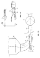
- FIG. 1A illustrates a common embodiment of the invention, in which a water in general, which has been meant for dilution of stock, and a high-consistency stock are mixed while making use of a wave-shaped pipe form.
- FIG. 1B is a sectional view taken along the line IV-IV in FIG. 1A on an enlarged scale.
- FIG. 1C is an illustration of principle of the short circulation in a paper/board machine, in which white water that has been recovered as retention is passed into the wire pit, white water being passed from the bottom of the wire pit as a return circulation into the headbox.
- FIG. 1D is an illustration on a larger scale of an arrangement of equipment in accordance with the invention in which feed pipes of stock and of the return circulation are passed into connection with the white water passed from the bottom portion of the wire pit.
- FIG. 2A shows a first embodiment of the invention, in which the wave-shaped form has been formed onto the inner wall of the pipe 11 connected with the wire pit.
- FIG. 2B is a sectional view taken along the line I-I in FIG. 2A .
- FIG. 3A shows a second embodiment of the invention, in which the wave shape has been formed onto a pipe 13 passed in the interior of the pipe 12 .
- FIG. 3B is a sectional view taken along the line II-II in FIG. 3A .
- FIG. 4A shows an embodiment of the invention, in which the wave-shaped form has been formed onto the pipe 12 .
- FIG. 4B is a sectional view taken along the line III-III in FIG. 4A .
- FIG. 1A illustrates the commonest embodiment of the invention, in which the water V used for dilution of fresh stock M is passed through the pipe 11 , and the high-consistency fresh stock M is passed through the pipe 13 .
- the high-consistency stock M and the water V used for dilution of the stock are mixed with each other owing to the wave formation in accordance with the invention at the end of the pipe 13 .
- the wave form extends both to the interior of the pipe 13 and to the outer face of the pipe 13 , in which case the mixing of the water V used for dilution of the fresh stock M with the fresh stock M is efficient.
- the water passed along the pipe 11 and used for dilution of the stock is favourably white water, which is passed, in the way shown in FIG. 1A , from a wire pit tank 100 .
- the wire pit tank 10 is a deaeration tank of the short circulation in a paper or board machine, into which tank the white water V is passed from a separate intermediate tank.
- the dilution water favourably consists of the white water of the short circulation in the paper/board machine.
- FIG. 1B is a sectional view taken along the line IV-IV in FIG. 1A .
- the line of supply of the high-consistency stock preferably a pipe 13
- the line of supply of the high-consistency stock is provided with a wave formation at its end.
- the waves extend both inside and outside of the circumference the pipe 13 , in which case they act both upon the fresh stock M flowing in the pipe 13 and upon the stock dilution water V, favourably white water, flowing outside the pipe 13 .
- FIG. 1C is an illustration of principle of the use of the white-water pit of the short circulation in a paper or board machine in collecting of retention waters and in recycling of fibrous white water, in which connection the fresh stock M and the water O of the return circulation are passed into connection with the white water V and in which construction, further, the combined mixed flow is passed from the wire pit 10 into connection with the headbox 100 of the paper or board machine.
- the white waters are passed from the wire into the wire pit 10 and into the duct 11 placed at the bottom of the wire pit 10
- the water O of the return circulation from the tank F and the fresh stock M from the stock tank S are also passed.
- the combined flow L 1 +L 2 +L 3 (as seen in FIG. 1D ) is passed further into the headbox 100 .
- the white water is mixed with the fresh stock and with the water of the return circulation, which water is, for example, a bypass flow circulation from the headbox or an accept from the second stage of vortex cleaning.
- the sequence of consistencies is as follows. The highest consistency is that of the high-consistency stock. The next consistency is that of the water from the return circulation, and the lowest consistency is that of the white water (white water ⁇ return circulation ⁇ high-consistency stock).
- FIG. 1D shows an equipment in accordance with the invention, in which, in the way indicated by the arrow L 1 , the fibrous water is passed from the white-water pit 10 back to circulation into the pipe 11 .
- the pipe 11 also fresh stock M is passed from the pipe 13 , and the water O of the return circulation is passed from the pipe 12 .
- the pipe 12 has been passed into the interior of the pipe 11 in an area in which the pipe 11 is curved and its cross-sectional flow area becomes narrower.
- the return circulation i.e. the water O of the return circulation
- the pipe 13 Centrally in the interior of the pipe 12 , there is the pipe 13 .
- the pipe 13 has been passed coaxially in the interior of the pipe 12 .
- the fresh stock M is passed into connection with the water O of the return circulation and with the white water V passed from the wire pit 10 .
- the pump P produces suction in the pipe 11 , and by means of the pump P the combined flow L 1 +L 2 +L 3 of the components V, M, O is passed further into connection with the headbox 100 of the paper/board machine.
- At least one of the pipes 11 , 12 or 13 is provided with a wave-shaped face form in a cross-section perpendicular to the longitudinal axis of the flow duct. Said wave-shaped face form produces what is called secondary vortexes, which promote the mixing together of the flows L 1 , L 2 and L 3 .
- FIG. 2A is a longitudinal sectional view of the mixing area K and of a first preferred embodiment of the invention.
- FIG. 2B is a sectional view taken along the line I-I in FIG. 2A .
- FIGS. 2A and 2B show an embodiment in which the pipe 11 has been provided with form pieces a 1 ,a 2 ,a 3 . . . , whose outer circumference becomes narrower in wedge shape, which have been fitted on the inner face of the pipe 11 , and which have been further shaped so that, as shown in the cross-sectional view, the maximal height of the wedge part a 1 ,a 2 ,a 3 . . . that produces the wave shape, in the middle of the wedge part a 1 , a 2 . . . , is placed in the area of the end of the pipe 12 that passes the water O of the return circulation.
- the pipe 13 that passes the stock M projects further from the interior of the pipe 12 .
- FIG. 3A is a longitudinal sectional view of a second embodiment of the invention.
- FIG. 3B is a sectional view taken along the line II-II in FIG. 3A .
- the wave shape has been formed onto the central pipe 13 fitted inside the pipe 12 .
- the pipe 13 projects from the pipe 12 .
- secondary vortexes are produced both in the flow L 2 of the return circulation water O inside the pipe 12 and in the flow L 3 of fresh stock M inside the pipe 13 .
- an effect that produces secondary vortexes is applied both to the return circulation water O flowing in the pipe 12 and to the stock M that flows in the pipe 13 .
- FIG. 4A is a longitudinal sectional view of a third preferred embodiment of the invention.
- FIG. 4B is a sectional view taken along the line III-III in FIG. 4A .
- FIGS. 4A and 4B show an embodiment of the invention in which the wave shape has been formed onto the flow pipe 12 so that the wave shape acts upon the flow L 1 of white water V in the pipe 11 and upon the flow L 2 of the return circulation water O in the pipe 12 .
Abstract
Description
Claims (20)
Applications Claiming Priority (3)
| Application Number | Priority Date | Filing Date | Title |
|---|---|---|---|
| FI981286 | 1998-06-05 | ||
| FI981286A FI104384B (en) | 1998-06-05 | 1998-06-05 | Apparatus and Method for Mixing Freshwater and Fresh Mass in a Post-Wastewater Canal |
| PCT/FI1999/000458 WO1999064666A1 (en) | 1998-06-05 | 1999-05-27 | Equipment and method in a paper or board machine for mixing of fresh stock and of water for dilution of fresh stock |
Related Parent Applications (1)
| Application Number | Title | Priority Date | Filing Date |
|---|---|---|---|
| PCT/FI1999/000458 Continuation WO1999064666A1 (en) | 1998-06-05 | 1999-05-27 | Equipment and method in a paper or board machine for mixing of fresh stock and of water for dilution of fresh stock |
Publications (2)
| Publication Number | Publication Date |
|---|---|
| US20060096730A1 US20060096730A1 (en) | 2006-05-11 |
| US7318883B2 true US7318883B2 (en) | 2008-01-15 |
Family
ID=8551916
Family Applications (1)
| Application Number | Title | Priority Date | Filing Date |
|---|---|---|---|
| US09/719,029 Active 2024-05-17 US7318883B2 (en) | 1998-06-05 | 2000-12-05 | Equipment and method in a paper or board machine for mixing of fresh stock and of water for dilution of fresh stock |
Country Status (11)
| Country | Link |
|---|---|
| US (1) | US7318883B2 (en) |
| EP (1) | EP1102885B1 (en) |
| JP (1) | JP4279460B2 (en) |
| KR (1) | KR100532151B1 (en) |
| AT (1) | ATE261017T1 (en) |
| AU (1) | AU4517299A (en) |
| BR (1) | BR9911193B1 (en) |
| CA (1) | CA2334207C (en) |
| DE (1) | DE69915306T2 (en) |
| FI (1) | FI104384B (en) |
| WO (1) | WO1999064666A1 (en) |
Cited By (1)
| Publication number | Priority date | Publication date | Assignee | Title |
|---|---|---|---|---|
| CN106368040A (en) * | 2016-08-31 | 2017-02-01 | 江苏理文造纸有限公司 | Corrugated paper banner quantitative control device |
Families Citing this family (9)
| Publication number | Priority date | Publication date | Assignee | Title |
|---|---|---|---|---|
| ATE262611T1 (en) * | 1998-06-29 | 2004-04-15 | Voith Paper Patent Gmbh | METHOD AND DEVICE FOR MEASUREMENT OF FIBER SUSPENSIONS |
| FI114030B (en) * | 1999-10-12 | 2004-07-30 | Metso Paper Inc | Method and arrangement for mixing pulp components of papermaking |
| ATE448869T1 (en) * | 2001-02-21 | 2009-12-15 | Metso Paper Inc | ARRANGEMENT FOR MIXING STREAMS IN A PAPER PRODUCTION PROCESS |
| FI116147B (en) * | 2001-02-21 | 2005-09-30 | Metso Paper Inc | Mixing flows in papermaking process involves by feeding first flow through a tube, and feeding second flow into first flow via feed opening which is in connection with space limited by the tube |
| FI109300B (en) * | 2001-05-29 | 2002-06-28 | Metso Paper Inc | Feeding arrangement for the pulp in a paper or cardboard machine |
| DE102004054236B4 (en) * | 2004-11-10 | 2007-06-06 | Voith Patent Gmbh | Method for mixing suspensions of different compositions |
| FI123392B (en) | 2008-02-22 | 2013-03-28 | Upm Kymmene Oyj | Method for Precipitation of Calcium Carbonate in a Fibrous Web Process and Fiber Machine Machine Approach |
| AT506577B1 (en) * | 2008-06-26 | 2009-10-15 | Gruber & Co Group Gmbh | STATIC MIXING DEVICE |
| EP3757288B1 (en) | 2019-06-28 | 2022-04-27 | Wetend Technologies Oy | A method of and an arrangement for adding a chemical to an approach flow system of a fiber web machine |
Citations (13)
| Publication number | Priority date | Publication date | Assignee | Title |
|---|---|---|---|---|
| US3812007A (en) * | 1969-04-04 | 1974-05-21 | Clark & Vicario Corp | Conduit system for conveying fibrous stock from deaerator chamber to headbox in papermaking machine |
| US3839145A (en) | 1970-09-17 | 1974-10-01 | K Bueckle | Apparatus for and method of forming a fiber suspension and for delivering it to the wire of a machine for manufacturing non-woven materials |
| US4021296A (en) | 1973-11-23 | 1977-05-03 | A. Ahlstrom Osakeyhtio | Method and device for manufacturing a continuous material web of elongated fibrous particles |
| US4808007A (en) * | 1982-05-13 | 1989-02-28 | Komax Systems, Inc. | Dual viscosity mixer |
| US4929088A (en) * | 1988-07-27 | 1990-05-29 | Vortab Corporation | Static fluid flow mixing apparatus |
| US5030326A (en) | 1988-05-13 | 1991-07-09 | S.E.M.T.I. Societe A Responsabilite Limitee | Paste-like mixture feed device |
| FI100168B (en) | 1989-02-10 | 1997-10-15 | Takeda Chemical Industries Ltd | Process for the preparation of an orally dispensable pharmaceutical preparation |
| US5839828A (en) * | 1996-05-20 | 1998-11-24 | Glanville; Robert W. | Static mixer |
| US6200417B1 (en) * | 1998-06-29 | 2001-03-13 | Voith Sulzer Papiertechnik Patent Gmbh | Process and device for mixing stock suspensions |
| US6277243B1 (en) * | 1998-07-09 | 2001-08-21 | Voith Sulzer Papiertechnik Patent Gmbh | Method for mixing and recirculating stock suspensions and water flows in the wet end of a paper machine |
| US6368462B1 (en) * | 1999-05-27 | 2002-04-09 | Valmet Corporation | Headbox for a paper or board making machine |
| US6740198B2 (en) * | 1999-10-12 | 2004-05-25 | Metso Paper Inc. | Method and arrangement for mixing pulp components in the manufacture of paper |
| US6986832B2 (en) * | 2001-02-21 | 2006-01-17 | Metso Paper Inc. | Arrangement for mixing flows in papermaking process |
-
1998
- 1998-06-05 FI FI981286A patent/FI104384B/en not_active IP Right Cessation
-
1999
- 1999-05-27 JP JP2000553653A patent/JP4279460B2/en not_active Expired - Lifetime
- 1999-05-27 EP EP99928040A patent/EP1102885B1/en not_active Expired - Lifetime
- 1999-05-27 AT AT99928040T patent/ATE261017T1/en active
- 1999-05-27 BR BRPI9911193-4A patent/BR9911193B1/en not_active IP Right Cessation
- 1999-05-27 KR KR10-2000-7013674A patent/KR100532151B1/en not_active IP Right Cessation
- 1999-05-27 DE DE69915306T patent/DE69915306T2/en not_active Expired - Lifetime
- 1999-05-27 AU AU45172/99A patent/AU4517299A/en not_active Abandoned
- 1999-05-27 CA CA002334207A patent/CA2334207C/en not_active Expired - Fee Related
- 1999-05-27 WO PCT/FI1999/000458 patent/WO1999064666A1/en active IP Right Grant
-
2000
- 2000-12-05 US US09/719,029 patent/US7318883B2/en active Active
Patent Citations (14)
| Publication number | Priority date | Publication date | Assignee | Title |
|---|---|---|---|---|
| US3812007A (en) * | 1969-04-04 | 1974-05-21 | Clark & Vicario Corp | Conduit system for conveying fibrous stock from deaerator chamber to headbox in papermaking machine |
| US3839145A (en) | 1970-09-17 | 1974-10-01 | K Bueckle | Apparatus for and method of forming a fiber suspension and for delivering it to the wire of a machine for manufacturing non-woven materials |
| US4021296A (en) | 1973-11-23 | 1977-05-03 | A. Ahlstrom Osakeyhtio | Method and device for manufacturing a continuous material web of elongated fibrous particles |
| FI56221B (en) | 1973-11-23 | 1979-08-31 | Ahlstroem Oy | FOERFARANDE FOER FORMNING AV EN KONTINUERLIG MATERIALBANA AV FIBROESA PARTIKLAR OCH ANORDNING DAERFOER |
| US4808007A (en) * | 1982-05-13 | 1989-02-28 | Komax Systems, Inc. | Dual viscosity mixer |
| US5030326A (en) | 1988-05-13 | 1991-07-09 | S.E.M.T.I. Societe A Responsabilite Limitee | Paste-like mixture feed device |
| US4929088A (en) * | 1988-07-27 | 1990-05-29 | Vortab Corporation | Static fluid flow mixing apparatus |
| FI100168B (en) | 1989-02-10 | 1997-10-15 | Takeda Chemical Industries Ltd | Process for the preparation of an orally dispensable pharmaceutical preparation |
| US5839828A (en) * | 1996-05-20 | 1998-11-24 | Glanville; Robert W. | Static mixer |
| US6200417B1 (en) * | 1998-06-29 | 2001-03-13 | Voith Sulzer Papiertechnik Patent Gmbh | Process and device for mixing stock suspensions |
| US6277243B1 (en) * | 1998-07-09 | 2001-08-21 | Voith Sulzer Papiertechnik Patent Gmbh | Method for mixing and recirculating stock suspensions and water flows in the wet end of a paper machine |
| US6368462B1 (en) * | 1999-05-27 | 2002-04-09 | Valmet Corporation | Headbox for a paper or board making machine |
| US6740198B2 (en) * | 1999-10-12 | 2004-05-25 | Metso Paper Inc. | Method and arrangement for mixing pulp components in the manufacture of paper |
| US6986832B2 (en) * | 2001-02-21 | 2006-01-17 | Metso Paper Inc. | Arrangement for mixing flows in papermaking process |
Cited By (1)
| Publication number | Priority date | Publication date | Assignee | Title |
|---|---|---|---|---|
| CN106368040A (en) * | 2016-08-31 | 2017-02-01 | 江苏理文造纸有限公司 | Corrugated paper banner quantitative control device |
Also Published As
| Publication number | Publication date |
|---|---|
| CA2334207C (en) | 2008-08-12 |
| JP2002517634A (en) | 2002-06-18 |
| EP1102885A1 (en) | 2001-05-30 |
| AU4517299A (en) | 1999-12-30 |
| FI981286A0 (en) | 1998-06-05 |
| WO1999064666A1 (en) | 1999-12-16 |
| BR9911193A (en) | 2001-02-06 |
| DE69915306T2 (en) | 2004-08-05 |
| ATE261017T1 (en) | 2004-03-15 |
| EP1102885B1 (en) | 2004-03-03 |
| CA2334207A1 (en) | 1999-12-16 |
| KR20010071383A (en) | 2001-07-28 |
| BR9911193B1 (en) | 2009-05-05 |
| DE69915306D1 (en) | 2004-04-08 |
| FI104384B (en) | 2000-01-14 |
| KR100532151B1 (en) | 2005-11-30 |
| JP4279460B2 (en) | 2009-06-17 |
| US20060096730A1 (en) | 2006-05-11 |
| FI981286A (en) | 1999-12-06 |
Similar Documents
| Publication | Publication Date | Title |
|---|---|---|
| US7318883B2 (en) | Equipment and method in a paper or board machine for mixing of fresh stock and of water for dilution of fresh stock | |
| US8202397B2 (en) | Method of and an arrangement for proportioning thick stock to a short circulation of fiber web machine | |
| US7758725B2 (en) | Method of mixing a paper making chemical into a fiber suspension flow | |
| US4477313A (en) | Method and apparatus for producing a multilayer paper web | |
| EP0745721B1 (en) | Stock feed system for a multi-layer headbox and method in the operation of a multi-layer headbox | |
| ATE272741T1 (en) | METHOD FOR SHORT COURSE IN A PAPER OR CARDBOARD MACHINE | |
| EP1070171B1 (en) | Application of a layer of admixture in the web former unit of a board machine | |
| US6368462B1 (en) | Headbox for a paper or board making machine | |
| EP0793750B1 (en) | Apparatus and process for screening a fibre suspension and process for producing paper utilizing the same | |
| US11459700B2 (en) | Method of and an arrangement for adding at least one additional stock component to an approach flow system of a fiber web machine | |
| CN112746513B (en) | Dilution water adding device and rotary drum pulper with same | |
| CA1145176A (en) | Method and apparatus for handling white water in a twin-wire machine | |
| US6083351A (en) | Dilution control device for a wet end of a paper-making machine | |
| US6841040B2 (en) | Method and device for feeding chemicals into a fibre suspension | |
| US20220195668A1 (en) | System for managing solids in papermaking whitewater | |
| US7001488B2 (en) | Method of and apparatus for distribution of paper stock in paper or board making machinery | |
| US20050051289A1 (en) | Former and headbox for said former | |
| WO2002025012A1 (en) | Method and apparatus for feeding chemicals into a liquid flow | |
| WO2004109010A1 (en) | Method for the manufacture of a multilayer web | |
| WO1999001608A1 (en) | Headbox of a papermachine/board machine |
Legal Events
| Date | Code | Title | Description |
|---|---|---|---|
| AS | Assignment |
Owner name: METSO PAPER, INC., FINLAND Free format text: CHANGE OF NAME;ASSIGNOR:VALMET CORPORATION;REEL/FRAME:012466/0973 Effective date: 20010101 |
|
| FEPP | Fee payment procedure |
Free format text: PAYER NUMBER DE-ASSIGNED (ORIGINAL EVENT CODE: RMPN); ENTITY STATUS OF PATENT OWNER: LARGE ENTITY Free format text: PAYOR NUMBER ASSIGNED (ORIGINAL EVENT CODE: ASPN); ENTITY STATUS OF PATENT OWNER: LARGE ENTITY |
|
| STCF | Information on status: patent grant |
Free format text: PATENTED CASE |
|
| FPAY | Fee payment |
Year of fee payment: 4 |
|
| AS | Assignment |
Owner name: VALMET TECHNOLOGIES, INC., FINLAND Free format text: CHANGE OF NAME;ASSIGNOR:METSO PAPER, INC.;REEL/FRAME:032551/0426 Effective date: 20131212 |
|
| FPAY | Fee payment |
Year of fee payment: 8 |
|
| MAFP | Maintenance fee payment |
Free format text: PAYMENT OF MAINTENANCE FEE, 12TH YEAR, LARGE ENTITY (ORIGINAL EVENT CODE: M1553); ENTITY STATUS OF PATENT OWNER: LARGE ENTITY Year of fee payment: 12 |