US720014A - Amusement apparatus. - Google Patents
Amusement apparatus. Download PDFInfo
- Publication number
- US720014A US720014A US9689202A US1902096892A US720014A US 720014 A US720014 A US 720014A US 9689202 A US9689202 A US 9689202A US 1902096892 A US1902096892 A US 1902096892A US 720014 A US720014 A US 720014A
- Authority
- US
- United States
- Prior art keywords
- boat
- sections
- flume
- gate
- water
- Prior art date
- Legal status (The legal status is an assumption and is not a legal conclusion. Google has not performed a legal analysis and makes no representation as to the accuracy of the status listed.)
- Expired - Lifetime
Links
Images

Classifications
-
- A—HUMAN NECESSITIES
- A63—SPORTS; GAMES; AMUSEMENTS
- A63G—MERRY-GO-ROUNDS; SWINGS; ROCKING-HORSES; CHUTES; SWITCHBACKS; SIMILAR DEVICES FOR PUBLIC AMUSEMENT
- A63G3/00—Water roundabouts, e.g. freely floating
Definitions
- My invention relates to amusement apparatus wherein persons seeking recreation and entertainment are transported in boats under the influence of an induced current over a course of water iiowing in an artificial chan ⁇ nel or flume amidst a diversity of novel and pleasing scenic effects.
- the object of the invention is to provide an apparatus of this character wherein the channel or flume will present in its course portions of varying pitch to accelerate the speed of the boat at predetermined points, wherein the level of the bulk of the flowing water will be maintained irrespective of the natural tendency to accumulate at the lowest point of the course, and wherein the means for so maintaining it is capable of automatic action to permit the unobstructed passage of the boat over the entire course.
- a further object is to provide an apparatus which will be so compact in its arrangement as to admit of the use of an extended course on a comparatively small ground-space and which can be operated economically.
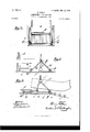
- Figure l is a side elevation of an amusement apparatus embodying my invention, portions of the housing therefor being broken away.
- Fig. 2 is a sectional elevation showing the relation of the diierent sections of the same continuous channel or flume.
- Fig. Bis a front elevation of one of the automatic lock-gates.
- Fig. 4 is a side elevation of the upper lock-gate; and
- Fig. 5 is a similar view of the lower lock-gate,
- I provide an outer housing A, inclosing the galleries B, wherein is an artificial channel Vor flume et.
- the inner walls of said galleries on each side of the said flume are equipped with such scenery or decorations as may be desired.
- a continuous current of flowing water is maintained in said fiume by means of the feed-pipe D, discharging into the section of the fiume occupying the highest elevation, the necessary water being drawn from any suitable source of supply, as the basin or tank C, into which the channel or fiume empties, and being forced through said pipe by any well-known means as a force-pump. (Not shown.)
- the iume a is comprised of sections occupying planes of relatively different elevations, which from their highest points descend gradually, the pitch preferably being from one-half to one inch to the hundred feet.
- the water discharged thereinto will therefore flow in a moderately-swift current only.
- These sections are connected by intermediate sections, as c c, the pitch of inclination of which is relatively greater than that of the adjoining sections to vary the speed of the boats at these points.
- I provide the gates l) b, to be more fully described in detail hereinafter, which gates are spaced apart to form a lock between them.
- these gates are so arranged (preferably by submerging to a limited extent) as to permit the continuous discharge of a portion of water therethrough or thereover.
- the pitch of the intermediate sections c c may be any desired degree, and thus enable the different sections of the fiume d to occupy planes of different elevation, the galleries when so desired being arranged one above the other to any desired number.
- p in the'upper section may be used.
- Each of the intermediate sections c is provided with rollers or Ways d, upon which the boat may glide, as it is apparent that a volume of water sufficient to oat the boat cannotl be economically maintained, although enough will pass continuously thereover, and
- the gates l) each com prise aframeb, hinged to the bed of the fiume ct, and a similar frame b2, hinged to said first-mentioned frame or united therewith by means of a toggle-joint c.
- the frame h2 is provided with a suitable facing.
- rollers F F Mounted in bearings on the upper side of these frames, respectively, are rollers F F, which are adapted to facilitate the passage of a boat thereover.
- I provide each with rollers G G,'carried by the frame b2, which move in ways formed by the bed ofthe fiume a and the guide f, suitable play being provided for to permit the free longitudinal movement ofsaid trame.
- a cleat as g, is secured to each side of the flume a, which presents an extended contact-surface to engage the frame h and reinforce it, thus relieving the various hinges from undue strain when the gate is closed.
- a counterbalance, as h, serves in conjunction with the force exerted by the current of water against the facing of the frame b2 to normally close said gate.
- I provide a supplemental gate J, adjoining the lock formed between the gates b b, respectively.
- the galleries B and their contained flume may take any desired course-direct and return, circular, or tortuous-to conform to the limitations imposed by the space to be occupied or other arbitrary requirements.
- the operation of my amusement apparatus is as follows:
- the flume a is filled withywater by means of the feed-pipe D and pump, (not shown,) which discharges into the section thereof occupying the highest plane and contiguous to the point of greatest elevation of said section.
- This section of the flume ills a portion of the water passes over or through the gates b b, over the intermediate sections c c to the section occupying the next lower plane, thus'inducing a continuous current of water, which action is repeated until the water traverses the entire length of the fiume and empties into the basin or tank ⁇ parts to their normal position.
- the upper gate is automatically closed by the action of the current on the facing of the frame h2, the counterbalancef roo serving to start and aid in the return of the As the boat leaves the lock after actuating the lower gate it descends theintermediate section c with the whole volume of Water contained in the lock and continues its course through the flume from section to section in this manner until the main basin C is reached.
- any number of inclined sections occupying planes of relatively different elevation may be utilized and that said sections may be disposed one'directly above the other, if desired, care being taken to render the flume Water-tight.
- the volume of water to maintain the necessary level throughout these sections and induce a continuous current is reduced to a minimum and the 'maintenance of the apparatus thus made economical.
- the vertically-depressible gates not only serve to prevent waste of water, but also increase the capacity of a plant and prevent the necessity of obstructing the upper portion of the galleries B.
- the said construction renders practicable the use of sections on different elevations and of variable pitch.
- a continu ⁇ ons channel or flume comprised of a plurality of sections disposed in planes of relatively different elevation and intermediate sections connecting said first-mentioned sections respectively, means for feeding water to said fiume and means whereby the water-level in ⁇ the various sections is maintained Vand a boat is permitted to pass successively from one section to another over said intermediate sections, in combination with means for transporting a boat to the starting-point of said fiume, substantially as described.
- a continuous channel or fiume comprised of a plurality of inclined sections occupying planes of relatively diiferent elevation and inclined intermediate sections of relatively greater pitch connecting said first-mentioned sections respectively, means for feeding water to said flume and means whereby the water-level is maintainedin the varioussectionsandaboatis permitted to pass successively from one section 1o another over said intermediate section, in combination with means for transporting a boat to the starting-point of said fiume, substantially as described.
- a continuous channel or Hume comprised of a plurality of inclined sections disposed in planes of relatively different elevation and inclined intermediate sections of relatively greater pitch connecting said rst-mentioned sections respectively, means for feeding water to said flume anda depressible gate above said intermediate sections respectively whereby the water-level in the various sections is maintained and a boat is permitted to pass Successively from one section to another over said intermediate sections, in combination with means for transporting a boat to the startingpoint of the flume, substantially as described.
- a continuous channel or fiume comprised of a plurality of sections disposed in planes of relatively diderent elevation and intermediate sections connecting said iirst-mentioned sections respectively, means for feeding water to said flume, an upper depressible gate and a lower depressible gate above said intermediate sections respectively and spaced apart to form an intermediate lock, whereby the waterlevel in the various sections is maintained and a boat is permitted to pass successively from one section to another over said intermediate sections, in combination with means for transporting a boat to the starting-point of the flume, substantially as described.
- a continuons channel or flume comprised of a plurality of inclined sections disposed in planes of relatively ,different elevation and intermediate inclined sections of relatively greater pitch connecting said first-mentioned sections respectively, means for feeding water to said flume, an upper depressible gate anda lower depressible gate above said intermediate sections respectively and spaced apart to form an intermediate lock, whereby the water-level in the various sections is maintained and a boat is permitted to pass successively from one section to the other over said intermediate sections, in combinationwith means for transporting a boat to the starting-point of the flu me, substantially as described.
- a continuous channel or flume comprised of a plurality of inclined sections disposed in planes of relatively different elevation and inclined intermediate sections of relatively greater pitch connecting said first-mentioned sections respectively, means for ⁇ feeding water to said fiume and a pair of gates above said intermediate sections respectively, said gates being spaced apart to forman intermediate lock and adapted to be automatically and successively actuated by a passing boat, whereby the water-level in the various sections is maintained and a boat is permitted to pass successively from one section to another over said intermediate sections, in combination with means for transporting a boat to the starting-point of the flume, substantially as described.
- a continuous channel or flume comprised of a plurality of inclined sections disposed in planes of relatively different elevation and inclined intermediate sections of relatively greater pitch connecting said first-mentioned sections respectively, means for feeding water to said nume, a pair of gates above saidintermediate sections respectively, said gates being spaced apart to form an intermediate lock and adapted to be automatically and successively actuated by a passing boat, whereby the waterlevel in. the various sections is maintained and a boat is permitted to pass successively from one section to another over said intermediate sections, and rollers or ways on said intermediate sections, in combination with means for transporting a boat to the starting-point of said flume, substantially as described.
- a continuous channel or ume in combination with an automatic gate comprised of two frames united bya toggle-joint, a pivotal connection between one of said frames and said channel or flume, a facing on the other of said frames, the said last-mentioned frame being capable of longitudinalmovement to permit said gate to be depressed by a passing boat, substantially as described.
- a continuous channel or flume in combination with an automatic gate comprising two framesnnited by a toggle-joint, a pivotal connection between one of said frames and said channel or flume, a facing on the other of said frames, the said last-mentioned frame being capable of longitudinal movement to permit said gate to be depressed by a passing boat, guides or ways whereby said longitudinal movement is controlled and side braces adapted to engage said first-mentioned frame and reinforce said gate when closed, substantially as described.
- a continuo us channel or flume in combination with an automatic gate comprising two frames united by a toggle-joint, a pivotal connection between one of said frames and said channelor flume, a facing on the other of said frames, the said last-mentioned frame being capable of longitudinal movement to permit said gate to be depressed bya passing boat, side braces adapted to engage said first-mentioned frame and reinforce said gate when closed, guides or ways whereby the longitudinal movement of saidframe is controlled and rollers carried by said gate whereby the passage of a boat thereoveris facilitated, substantially as de scribed.
- a continuous channel or flume in combination with an automatic gate comprising two frames united by a toggle-joint, a ivotal connection between lone of said frames and said channel or flume, a facing for the other ofsaid frames, the said last-mentioned frame being capable of longitudinal movement to permit said gate to be depressed by a passing boat, guides or Ways whereby said longitudinal movement is controlled, side braces adapted to engage said first-mentioned frame and reinforce said gate when closed, rollers carried by said gate whereby the passage of a boat thereover is facilitated, and a counterweight to aid in starting and returning said gate to the closed position, substantially as described.
Description
T. IoLKs.
AMUSEMENT APPARATUS. APPLICATION IILBD MAR. 6, 1902.
N0 MODES 2 SHEETS-SHEET l.
PAT'ENTED PEB. 1o, 1903.
www3? wim A TTU/NVE PATENTED PEBl 10, 1903.
T'. POLKS. AMUSBMBNT APPARATUS.
APPLICATION FILED MAR. 6. 1902.
2 SHEETS-SHEET Z.-
30 MODEL.
s .Qzw-- BY 6) Jim1 of ,t E SSES QU/WMM.
A TTOHN Nrrnn STATES PATENT OFFICE.
THOMAS FOLKS, OF BROOKLYN, NEVV'YORK.
AM U'SEIVI ENT APPARATUS.
SPECIFICATION forming part of Letters Patent No. '7 20,0 14, dated iFebruary. 10, 1903.
Application filed March 6, 1902.
To all whom 7225 may concern:
Be it known that I, THOMAS FoLKs, a citi- Zen of the United States, residing at Coney Island, in the borough of Brooklyn, city of New York, county of Kings, and State of New York, have invented certain new and useful Improvements in Amusement Apparatus, of which the following is a specification, reference being had therein to the accompanying drawings.
My invention relates to amusement apparatus wherein persons seeking recreation and entertainment are transported in boats under the influence of an induced current over a course of water iiowing in an artificial chan` nel or flume amidst a diversity of novel and pleasing scenic effects.
The object of the invention is to provide an apparatus of this character wherein the channel or flume will present in its course portions of varying pitch to accelerate the speed of the boat at predetermined points, wherein the level of the bulk of the flowing water will be maintained irrespective of the natural tendency to accumulate at the lowest point of the course, and wherein the means for so maintaining it is capable of automatic action to permit the unobstructed passage of the boat over the entire course.
A further object is to provide an apparatus which will be so compact in its arrangement as to admit of the use of an extended course on a comparatively small ground-space and which can be operated economically.
The invention consists in the novel features of construction hereinafter set forth and described, and more particularly pointed out in the claims hereto appended.
Referring to the drawings, Figure lis a side elevation of an amusement apparatus embodying my invention, portions of the housing therefor being broken away. Fig. 2 is a sectional elevation showing the relation of the diierent sections of the same continuous channel or flume. Fig. Bis a front elevation of one of the automatic lock-gates. Fig. 4 is a side elevation of the upper lock-gate; and Fig. 5 is a similar view of the lower lock-gate,
showing the position assumed by the various serai No. 96,892. or@ man parts thereof during the passage of a boat thereover.
Like letters refer to like parts throughout the several views.
In the practice of my invention I provide an outer housing A, inclosing the galleries B, wherein is an artificial channel Vor flume et. The inner walls of said galleries on each side of the said flume are equipped with such scenery or decorations as may be desired. A continuous current of flowing water is maintained in said fiume by means of the feed-pipe D, discharging into the section of the fiume occupying the highest elevation, the necessary water being drawn from any suitable source of supply, as the basin or tank C, into which the channel or fiume empties, and being forced through said pipe by any well-known means as a force-pump. (Not shown.)
The iume a, is comprised of sections occupying planes of relatively different elevations, which from their highest points descend gradually, the pitch preferably being from one-half to one inch to the hundred feet. The water discharged thereinto will therefore flow in a moderately-swift current only. These sections are connected by intermediate sections, as c c, the pitch of inclination of which is relatively greater than that of the adjoining sections to vary the speed of the boats at these points. To maintain the head of water above these intermediate sections c c, I provide the gates l) b, to be more fully described in detail hereinafter, which gates are spaced apart to form a lock between them. To prevent the backing up of water above said gates and the consequent interference with the current, these gates are so arranged (preferably by submerging to a limited extent) as to permit the continuous discharge of a portion of water therethrough or thereover. By this ar- .rangement of gates the pitch of the intermediate sections c c may be any desired degree, and thus enable the different sections of the fiume d to occupy planes of different elevation, the galleries when so desired being arranged one above the other to any desired number.
p in the'upper section may be used.
Each of the intermediate sections c is provided with rollers or Ways d, upon which the boat may glide, as it is apparent that a volume of water sufficient to oat the boat cannotl be economically maintained, although enough will pass continuously thereover, and
particularly so With the passage of the boatv from the lock, to create the effect of rapids and conceal the said ways or rollers CZ.
The gates l) each com prise aframeb, hinged to the bed of the fiume ct, and a similar frame b2, hinged to said first-mentioned frame or united therewith by means of a toggle-joint c. The frame h2 is provided with a suitable facing. Mounted in bearings on the upper side of these frames, respectively, are rollers F F, which are adapted to facilitate the passage of a boat thereover. To control more perfectly the movement of the said gates, I provide each with rollers G G,'carried by the frame b2, which move in ways formed by the bed ofthe fiume a and the guide f, suitable play being provided for to permit the free longitudinal movement ofsaid trame. A cleat, as g, is secured to each side of the flume a, which presents an extended contact-surface to engage the frame h and reinforce it, thus relieving the various hinges from undue strain when the gate is closed. A counterbalance, as h, serves in conjunction with the force exerted by the current of water against the facing of the frame b2 to normally close said gate.
To prevent the continuous flow of water from one inclined section to another occupying a lower plane when the apparatus is closed down, I provide a supplemental gate J, adjoining the lock formed between the gates b b, respectively.
Any desired means of transporting the boats and their loads from the lower sections to the starting-point or source of the fiume a In the drawings I have shown an ordinary lift E, although an inclined plane may be substituted therefor when the space to be occupied will admit of such a construction.
The galleries B and their contained flume may take any desired course-direct and return, circular, or tortuous-to conform to the limitations imposed by the space to be occupied or other arbitrary requirements.
The operation of my amusement apparatus, in so far as it has not already been described, is as follows: The flume a is filled withywater by means of the feed-pipe D and pump, (not shown,) which discharges into the section thereof occupying the highest plane and contiguous to the point of greatest elevation of said section. As this section of the flume ills a portion of the water passes over or through the gates b b, over the intermediate sections c c to the section occupying the next lower plane, thus'inducing a continuous current of water, which action is repeated until the water traverses the entire length of the fiume and empties into the basin or tank `parts to their normal position.
C. -The arrangement of the said tank relative to the lower section being such as to prevent the complete discharge of said section thereinto, this current is maintained throughout the entire flume solely by the continued discharge of water from said feed-pipe and the withdrawal of a corresponding volume of water from said tank. A suitable current having been set up, a boat and its occupants are elevated by means of the lift E or its equivalen t--an inclined plane-to the section of the flume occupying the highest plane and introduced thereinto. As the boat enters the fiume it descends with the current in the direction indicated by the arrow in Fig. 4 until it contacts with the roller F on the upper folding gate b. The acquired momentum of the boat augmented by the force of the current thereon tends to force the boat upon said roller and over the crest of the said gate. The vertical pressure occasioned by the weight of the boat and the contour of its stem or bow, however, depresses said gate, the rollers G G moving longitudinally in their ways to permit said depression. As the boat passes over the upper gate, as shown in Fig. l, which movement is facilitated by the rollers F F, with which it contacts, sufficient water enters the lock' with the boat to fill it. As the boat passes from said gate and prior to the actuation of the lower gate in a similar manner the upper gate is automatically closed by the action of the current on the facing of the frame h2, the counterbalancef roo serving to start and aid in the return of the As the boat leaves the lock after actuating the lower gate it descends theintermediate section c with the whole volume of Water contained in the lock and continues its course through the flume from section to section in this manner until the main basin C is reached.
It will be observed that by the construction hereiubefore described any number of inclined sections occupying planes of relatively different elevation may be utilized and that said sections may be disposed one'directly above the other, if desired, care being taken to render the flume Water-tight. The volume of water to maintain the necessary level throughout these sections and induce a continuous current, by reason of the gates h b or either of them, is reduced to a minimum and the 'maintenance of the apparatus thus made economical. The vertically-depressible gates not only serve to prevent waste of water, but also increase the capacity of a plant and prevent the necessity of obstructing the upper portion of the galleries B. Furthermore, the said construction renders practicable the use of sections on different elevations and of variable pitch.
It is apparent that therev may be many deviations from the construction herein shown and described Without departing from the spirit of my invention, both as to the exact IIO arrangement of the gates and their number and in the minor details of their construction. It is not my intention, therefore, to limit the invention to the precise construction herein shown and described.
The course of the flume is immaterial, and no claim is made as to such.
Having described my invention, what I claim as new, and desire to have protected by Letters Patent, is
l. In an amusement apparatus, a continu` ons channel or flume comprised of a plurality of sections disposed in planes of relatively different elevation and intermediate sections connecting said first-mentioned sections respectively, means for feeding water to said fiume and means whereby the water-level in `the various sections is maintained Vand a boat is permitted to pass successively from one section to another over said intermediate sections, in combination with means for transporting a boat to the starting-point of said fiume, substantially as described.
2. In an amusement apparatus, a continuous channel or fiume comprised of a plurality of inclined sections occupying planes of relatively diiferent elevation and inclined intermediate sections of relatively greater pitch connecting said first-mentioned sections respectively, means for feeding water to said flume and means whereby the water-level is maintainedin the varioussectionsandaboatis permitted to pass successively from one section 1o another over said intermediate section, in combination with means for transporting a boat to the starting-point of said fiume, substantially as described.
3. In an amusement apparatus, a continuous channel or Hume comprised of a plurality of inclined sections disposed in planes of relatively different elevation and inclined intermediate sections of relatively greater pitch connecting said rst-mentioned sections respectively, means for feeding water to said flume anda depressible gate above said intermediate sections respectively whereby the water-level in the various sections is maintained and a boat is permitted to pass Successively from one section to another over said intermediate sections, in combination with means for transporting a boat to the startingpoint of the flume, substantially as described.
4. In an amusement apparatus, a continuous channel or fiume comprised of a plurality of sections disposed in planes of relatively diderent elevation and intermediate sections connecting said iirst-mentioned sections respectively, means for feeding water to said flume, an upper depressible gate and a lower depressible gate above said intermediate sections respectively and spaced apart to form an intermediate lock, whereby the waterlevel in the various sections is maintained and a boat is permitted to pass successively from one section to another over said intermediate sections, in combination with means for transporting a boat to the starting-point of the flume, substantially as described.
5. In an amusement apparatus, a continuons channel or flume comprised of a plurality of inclined sections disposed in planes of relatively ,different elevation and intermediate inclined sections of relatively greater pitch connecting said first-mentioned sections respectively, means for feeding water to said flume, an upper depressible gate anda lower depressible gate above said intermediate sections respectively and spaced apart to form an intermediate lock, whereby the water-level in the various sections is maintained and a boat is permitted to pass successively from one section to the other over said intermediate sections, in combinationwith means for transporting a boat to the starting-point of the flu me, substantially as described.
6. In an amusement apparatus, a continuous channel or flume comprised of a plurality of inclined sections disposed in planes of relatively different elevation and inclined intermediate sections of relatively greater pitch connecting said first-mentioned sections respectively, means for `feeding water to said fiume and a pair of gates above said intermediate sections respectively, said gates being spaced apart to forman intermediate lock and adapted to be automatically and successively actuated by a passing boat, whereby the water-level in the various sections is maintained and a boat is permitted to pass successively from one section to another over said intermediate sections, in combination with means for transporting a boat to the starting-point of the flume, substantially as described.
V7. In an amusement apparatus, a continuous channel or flume comprised of a plurality of inclined sections disposed in planes of relatively different elevation and inclined intermediate sections of relatively greater pitch connecting said first-mentioned sections respectively, means for feeding water to said nume, a pair of gates above saidintermediate sections respectively, said gates being spaced apart to form an intermediate lock and adapted to be automatically and successively actuated by a passing boat, whereby the waterlevel in. the various sections is maintained and a boat is permitted to pass successively from one section to another over said intermediate sections, and rollers or ways on said intermediate sections, in combination with means for transporting a boat to the starting-point of said flume, substantially as described.
8. In an amusement apparatus,- a continuous channel or fiume in combination with an automatic gate comprised of two frames united by a toggle-joint, a pivotal connection between one of said frames and said channel or fiume, a'facing on the other of said frames, the said last-mentioned frame being capable of longitudinal movement to permit said gate ICO IIO
'to'be depressed by a passing boat and guides or ways whereby said longitudinal movement is controlled, substantially as described.
9. In an amusementJ apparatus, a continuous channel or ume, in combination with an automatic gate comprised of two frames united bya toggle-joint, a pivotal connection between one of said frames and said channel or flume, a facing on the other of said frames, the said last-mentioned frame being capable of longitudinalmovement to permit said gate to be depressed by a passing boat, substantially as described.
10 In an amusement apparatus, a continuous channel or flume in combination with an automatic gate comprising two framesnnited by a toggle-joint, a pivotal connection between one of said frames and said channel or flume, a facing on the other of said frames, the said last-mentioned frame being capable of longitudinal movement to permit said gate to be depressed by a passing boat, guides or ways whereby said longitudinal movement is controlled and side braces adapted to engage said first-mentioned frame and reinforce said gate when closed, substantially as described.
ll. In an amusement apparatus, a continuo us channel or flume in combination with an automatic gate comprising two frames united by a toggle-joint, a pivotal connection between one of said frames and said channelor flume, a facing on the other of said frames, the said last-mentioned frame being capable of longitudinal movement to permit said gate to be depressed bya passing boat, side braces adapted to engage said first-mentioned frame and reinforce said gate when closed, guides or ways whereby the longitudinal movement of saidframe is controlled and rollers carried by said gate whereby the passage of a boat thereoveris facilitated, substantially as de scribed.
l2. In an amusement apparatus, a continuous channel or flume in combination with an automatic gate comprising two frames united by a toggle-joint, a ivotal connection between lone of said frames and said channel or flume, a facing for the other ofsaid frames, the said last-mentioned frame being capable of longitudinal movement to permit said gate to be depressed by a passing boat, guides or Ways whereby said longitudinal movement is controlled, side braces adapted to engage said first-mentioned frame and reinforce said gate when closed, rollers carried by said gate whereby the passage of a boat thereover is facilitated, and a counterweight to aid in starting and returning said gate to the closed position, substantially as described.
In Witness whereof I have hereunto affixed my signature, this 4th day of March, 1902, in the presence of two witnesses.
THOMAS FOLKS.
Witnesses:
F. T. WENTWORTH, M. OBRIEN.
Priority Applications (1)
| Application Number | Priority Date | Filing Date | Title |
|---|---|---|---|
| US9689202A US720014A (en) | 1902-03-06 | 1902-03-06 | Amusement apparatus. |
Applications Claiming Priority (1)
| Application Number | Priority Date | Filing Date | Title |
|---|---|---|---|
| US9689202A US720014A (en) | 1902-03-06 | 1902-03-06 | Amusement apparatus. |
Publications (1)
| Publication Number | Publication Date |
|---|---|
| US720014A true US720014A (en) | 1903-02-10 |
Family
ID=2788529
Family Applications (1)
| Application Number | Title | Priority Date | Filing Date |
|---|---|---|---|
| US9689202A Expired - Lifetime US720014A (en) | 1902-03-06 | 1902-03-06 | Amusement apparatus. |
Country Status (1)
| Country | Link |
|---|---|
| US (1) | US720014A (en) |
Cited By (20)
| Publication number | Priority date | Publication date | Assignee | Title |
|---|---|---|---|---|
| US20020082097A1 (en) * | 2000-09-11 | 2002-06-27 | Henry Jeffrey W. | Water amusement system and method |
| US20050090322A1 (en) * | 2003-10-24 | 2005-04-28 | Henry, Schooley & Associates, L.L.C. | Method and system of participant identifiers for water amusement parks |
| US20060111195A1 (en) * | 2004-11-24 | 2006-05-25 | Henry Jeffery W | Water amusement park conveyors |
| US20060111196A1 (en) * | 2004-11-24 | 2006-05-25 | Henry Jeffery W | Rollable carrier ride |
| US20070033867A1 (en) * | 2005-04-20 | 2007-02-15 | Henry Jeffery W | Composite tree |
| US20070049385A1 (en) * | 2005-08-30 | 2007-03-01 | Henry Jeffery W | Water amusement park conveyor barriers |
| US20070049387A1 (en) * | 2005-08-03 | 2007-03-01 | Henry Jeffery W | Water amusement park water channel flow system |
| US20070049386A1 (en) * | 2005-08-30 | 2007-03-01 | Henry Jeffery W | Adjusting participant flow rate in water amusement parks |
| US20070060402A1 (en) * | 2005-08-30 | 2007-03-15 | Henry Jeffery W | Modular water amusement park conveyors |
| US20070060403A1 (en) * | 2005-08-30 | 2007-03-15 | Henry Jeffery W | Water amusement park conveyors |
| US20070087851A1 (en) * | 2005-09-02 | 2007-04-19 | Henry Jeffery W | Water amusement system and method including a self-contained floating marine park |
| US20070087850A1 (en) * | 2005-09-02 | 2007-04-19 | Henry Jeffery W | Amusement water rides involving interactive user environments |
| US20070219004A1 (en) * | 2006-03-14 | 2007-09-20 | Henry Jeffery W | Method and system of positionable covers for water amusement parks |
| US20080032806A1 (en) * | 2002-03-25 | 2008-02-07 | Nbgs International, Inc. | Control system for water amusement devices |
| US7762899B2 (en) | 2005-08-30 | 2010-07-27 | Water Ride Concepts, Inc. | Water amusement park conveyor support elements |
| US7775895B2 (en) | 2005-08-03 | 2010-08-17 | Water Ride Concepts, Inc. | Water amusement park water channel and adjustable flow controller |
| US7857704B2 (en) | 2005-09-15 | 2010-12-28 | Water Ride Concepts, Inc. | Amusement water rides involving games of chance |
| US8079916B2 (en) | 2008-12-18 | 2011-12-20 | Water Ride Concepts, Inc. | Themed amusement river ride system |
| US8210954B2 (en) | 2005-09-02 | 2012-07-03 | Water Ride Concepts, Inc. | Amusement water rides involving exercise circuits |
| RU2687812C2 (en) * | 2014-10-07 | 2019-05-16 | ЮНИВЕРСАЛ СИТИ СТЬЮДИОС ЭлЭлСи | System of actuated movable platforms |
-
1902
- 1902-03-06 US US9689202A patent/US720014A/en not_active Expired - Lifetime
Cited By (59)
| Publication number | Priority date | Publication date | Assignee | Title |
|---|---|---|---|---|
| US20020082097A1 (en) * | 2000-09-11 | 2002-06-27 | Henry Jeffrey W. | Water amusement system and method |
| US20050085306A1 (en) * | 2000-09-11 | 2005-04-21 | Nbgs International, Inc | Conveyor system and method for water amusement parks |
| US20050090321A1 (en) * | 2000-09-11 | 2005-04-28 | Nbgs International, Inc. | Conveyor control system and method for water amusement parks |
| US8070615B2 (en) | 2000-09-11 | 2011-12-06 | Water Ride Concepts, Inc. | Methods and systems for water amusement conveyor |
| US20050090320A1 (en) * | 2000-09-11 | 2005-04-28 | Nbgs International, Inc | Water amusement method |
| US7740542B2 (en) | 2000-09-11 | 2010-06-22 | Water Ride Concepts, Inc. | Water amusement method |
| US7491128B2 (en) | 2000-09-11 | 2009-02-17 | Nbgs International, Inc. | Conveyor system and method for water amusement parks |
| US7371182B2 (en) | 2000-09-11 | 2008-05-13 | Nbgs International, Inc. | Conveyor control system and method for water amusement parks |
| US7285053B2 (en) | 2000-09-11 | 2007-10-23 | Nbgs International, Inc. | Water amusement system and method |
| US8197352B2 (en) | 2000-09-11 | 2012-06-12 | Water Ride Concepts, Inc. | Methods and systems for amusement park conveyor belt systems |
| US8096892B2 (en) | 2002-03-25 | 2012-01-17 | Water Ride Concepts, Inc. | Control system for water amusement devices |
| US20080032806A1 (en) * | 2002-03-25 | 2008-02-07 | Nbgs International, Inc. | Control system for water amusement devices |
| US7775894B2 (en) | 2003-10-24 | 2010-08-17 | Water Ride Concepts, Inc. | Method and system of participant identifiers for water amusement parks |
| US7229359B2 (en) | 2003-10-24 | 2007-06-12 | Henry, Schooley & Associates, L.L.C. | Continuous water ride |
| US20050090322A1 (en) * | 2003-10-24 | 2005-04-28 | Henry, Schooley & Associates, L.L.C. | Method and system of participant identifiers for water amusement parks |
| US8075413B2 (en) | 2003-10-24 | 2011-12-13 | Water Ride Concepts, Inc. | Continuous water ride method and system for water amusement parks |
| US20060142090A1 (en) * | 2004-11-24 | 2006-06-29 | Henry, Schooley & Associates, L.L.C. | Water amusement park multiple path conveyors |
| US20060135274A1 (en) * | 2004-11-24 | 2006-06-22 | Henry, Schooley & Associates, L.L.C. | Water amusement park conveyor roller belts |
| US20060111195A1 (en) * | 2004-11-24 | 2006-05-25 | Henry Jeffery W | Water amusement park conveyors |
| US7942752B2 (en) | 2004-11-24 | 2011-05-17 | Water Ride Concepts, Inc. | Water amusement park multiple path conveyors |
| US7597630B2 (en) | 2004-11-24 | 2009-10-06 | Water Ride Concepts, Inc. | Water amusement park conveyors |
| US7497784B2 (en) | 2004-11-24 | 2009-03-03 | Water Ride Concepts, Inc. | Rollable carrier ride |
| US20060111196A1 (en) * | 2004-11-24 | 2006-05-25 | Henry Jeffery W | Rollable carrier ride |
| US8162769B2 (en) | 2004-11-24 | 2012-04-24 | Water Ride Concepts, Inc. | Water amusement park conveyor roller belts |
| US20070033867A1 (en) * | 2005-04-20 | 2007-02-15 | Henry Jeffery W | Composite tree |
| US7785207B2 (en) | 2005-04-20 | 2010-08-31 | Water Ride Concepts, Inc. | Water amusement system with elevated structure |
| US20070033866A1 (en) * | 2005-04-20 | 2007-02-15 | Henry Jeffery W | Lift apparatus for base-mounted plant |
| US7921601B2 (en) | 2005-04-20 | 2011-04-12 | Water Ride Concepts, Inc. | Water amusement system with trees |
| US20070051037A1 (en) * | 2005-04-20 | 2007-03-08 | Henry Jeffery W | Thematic tree system |
| US20070049387A1 (en) * | 2005-08-03 | 2007-03-01 | Henry Jeffery W | Water amusement park water channel flow system |
| US7727077B2 (en) | 2005-08-03 | 2010-06-01 | Water Ride Concepts, Inc. | Water amusement park water channel flow system |
| US7775895B2 (en) | 2005-08-03 | 2010-08-17 | Water Ride Concepts, Inc. | Water amusement park water channel and adjustable flow controller |
| US20070049386A1 (en) * | 2005-08-30 | 2007-03-01 | Henry Jeffery W | Adjusting participant flow rate in water amusement parks |
| US20070060403A1 (en) * | 2005-08-30 | 2007-03-15 | Henry Jeffery W | Water amusement park conveyors |
| US8282497B2 (en) | 2005-08-30 | 2012-10-09 | Water Ride Concepts, Inc. | Modular water amusement park conveyors |
| US20070049385A1 (en) * | 2005-08-30 | 2007-03-01 | Henry Jeffery W | Water amusement park conveyor barriers |
| US7762899B2 (en) | 2005-08-30 | 2010-07-27 | Water Ride Concepts, Inc. | Water amusement park conveyor support elements |
| US20070060402A1 (en) * | 2005-08-30 | 2007-03-15 | Henry Jeffery W | Modular water amusement park conveyors |
| US7815514B2 (en) | 2005-08-30 | 2010-10-19 | Water Ride Concepts, Inc. | Water amusement park conveyor barriers |
| US7371183B2 (en) | 2005-08-30 | 2008-05-13 | Henry, Schooley & Associates, L.L.C. | Water amusement park conveyors |
| US7758435B2 (en) | 2005-09-02 | 2010-07-20 | Water Ride Concepts, Inc. | Amusement water rides involving interactive user environments |
| US7775896B2 (en) | 2005-09-02 | 2010-08-17 | Water Ride Concepts, Inc. | Methods and systems for self-contained floating marine parks |
| US20070087850A1 (en) * | 2005-09-02 | 2007-04-19 | Henry Jeffery W | Amusement water rides involving interactive user environments |
| US20070087851A1 (en) * | 2005-09-02 | 2007-04-19 | Henry Jeffery W | Water amusement system and method including a self-contained floating marine park |
| US7780536B2 (en) | 2005-09-02 | 2010-08-24 | Water Ride Concepts, Inc. | Methods and systems for positionable screen for self-contained floating marine parks |
| US20070087853A1 (en) * | 2005-09-02 | 2007-04-19 | Henry Jeffery W | Methods and systems for active filtration of portions of self-contained floating marine parks |
| US20110118039A1 (en) * | 2005-09-02 | 2011-05-19 | Water Ride Concepts, Inc. | Methods and systems for viewing marine life from self-contained floating marine parks |
| US7828667B2 (en) | 2005-09-02 | 2010-11-09 | Water Ride Concepts, Inc. | Methods and systems for active filtration of portions of self-contained floating marine parks |
| US8663023B2 (en) | 2005-09-02 | 2014-03-04 | Water Ride Concepts, Inc. | Methods and systems for viewing marine life from self-contained floating marine parks |
| US7766753B2 (en) | 2005-09-02 | 2010-08-03 | Water Ride Concepts, Inc. | Methods and systems for modular self-contained floating marine parks |
| US8210954B2 (en) | 2005-09-02 | 2012-07-03 | Water Ride Concepts, Inc. | Amusement water rides involving exercise circuits |
| US7811177B2 (en) | 2005-09-02 | 2010-10-12 | Water Ride Concepts, Inc. | Water amusement system and method including a self-contained floating marine park |
| US7857704B2 (en) | 2005-09-15 | 2010-12-28 | Water Ride Concepts, Inc. | Amusement water rides involving games of chance |
| US20070219004A1 (en) * | 2006-03-14 | 2007-09-20 | Henry Jeffery W | Method and system of positionable covers for water amusement parks |
| US8251832B2 (en) | 2006-03-14 | 2012-08-28 | Water Ride Concepts, Inc. | Method and system of positionable covers for water amusement parks |
| US7762900B2 (en) | 2006-03-14 | 2010-07-27 | Water Ride Concepts, Inc. | Method and system of positionable covers for water amusement parks |
| US20110014988A1 (en) * | 2006-03-14 | 2011-01-20 | Water Ride Concepts, Inc. | Method and system of positionable covers for water amusement parks |
| US8079916B2 (en) | 2008-12-18 | 2011-12-20 | Water Ride Concepts, Inc. | Themed amusement river ride system |
| RU2687812C2 (en) * | 2014-10-07 | 2019-05-16 | ЮНИВЕРСАЛ СИТИ СТЬЮДИОС ЭлЭлСи | System of actuated movable platforms |
Similar Documents
| Publication | Publication Date | Title |
|---|---|---|
| US720014A (en) | Amusement apparatus. | |
| US728894A (en) | Amusement apparatus. | |
| US724040A (en) | Pleasure-waterway. | |
| US952673A (en) | Amusement apparatus. | |
| US654980A (en) | Logging-exhibition apparatus. | |
| US828689A (en) | Amusement apparatus. | |
| US664179A (en) | Pleasure-canal. | |
| US572426A (en) | Artificial slide and lake and conveyer therefor | |
| US1167993A (en) | Amusement apparatus. | |
| US757286A (en) | Amusement apparatus. | |
| US561223A (en) | hamilton | |
| US779464A (en) | Whirlpool for public amusement. | |
| US760503A (en) | Wonderland scenic waterway. | |
| US774917A (en) | Amusement apparatus. | |
| US1016808A (en) | Submarine pleasure apparatus. | |
| US797095A (en) | Marine-illusion apparatus. | |
| US848061A (en) | Amusement apparatus. | |
| US739236A (en) | Scenic apparatus. | |
| US595951A (en) | Illusion apparatus | |
| US322602A (en) | Pool-ball rack and spotter | |
| US474487A (en) | Henry b | |
| US953459A (en) | Amusement apparatus. | |
| US468792A (en) | critchlow | |
| US546528A (en) | haqen | |
| US367055A (en) | Joseph ollee |