US7159983B2 - Multifocal lenses for pre-presbyopic individuals - Google Patents
Multifocal lenses for pre-presbyopic individuals Download PDFInfo
- Publication number
- US7159983B2 US7159983B2 US10/978,165 US97816504A US7159983B2 US 7159983 B2 US7159983 B2 US 7159983B2 US 97816504 A US97816504 A US 97816504A US 7159983 B2 US7159983 B2 US 7159983B2
- Authority
- US
- United States
- Prior art keywords
- lens
- conic
- aspheric
- curvature
- astigmatism
- Prior art date
- Legal status (The legal status is an assumption and is not a legal conclusion. Google has not performed a legal analysis and makes no representation as to the accuracy of the status listed.)
- Active, expires
Links
Images


Classifications
-
- G—PHYSICS
- G02—OPTICS
- G02C—SPECTACLES; SUNGLASSES OR GOGGLES INSOFAR AS THEY HAVE THE SAME FEATURES AS SPECTACLES; CONTACT LENSES
- G02C7/00—Optical parts
- G02C7/02—Lenses; Lens systems ; Methods of designing lenses
- G02C7/06—Lenses; Lens systems ; Methods of designing lenses bifocal; multifocal ; progressive
- G02C7/061—Spectacle lenses with progressively varying focal power
- G02C7/063—Shape of the progressive surface
- G02C7/066—Shape, location or size of the viewing zones
-
- G—PHYSICS
- G02—OPTICS
- G02C—SPECTACLES; SUNGLASSES OR GOGGLES INSOFAR AS THEY HAVE THE SAME FEATURES AS SPECTACLES; CONTACT LENSES
- G02C7/00—Optical parts
- G02C7/02—Lenses; Lens systems ; Methods of designing lenses
- G02C7/024—Methods of designing ophthalmic lenses
- G02C7/028—Special mathematical design techniques
-
- G—PHYSICS
- G02—OPTICS
- G02C—SPECTACLES; SUNGLASSES OR GOGGLES INSOFAR AS THEY HAVE THE SAME FEATURES AS SPECTACLES; CONTACT LENSES
- G02C7/00—Optical parts
- G02C7/02—Lenses; Lens systems ; Methods of designing lenses
- G02C7/06—Lenses; Lens systems ; Methods of designing lenses bifocal; multifocal ; progressive
- G02C7/061—Spectacle lenses with progressively varying focal power
Definitions
- the present invention relates to multifocal ophthalmic lenses.
- the invention provides non-conic, aspheric lenses for pre-presbyopic individuals.
- Single vision lenses are routinely used to correct myopia, hyper-emetropia and astigmatism in wearers that are typically below 40 years of age. Above this age and with the onset of presbyopia, multifocal ophthalmic lenses such as bifocals, trifocal and progressive addition lenses (“PALs”) are used for the treatment of presbyopia.
- multifocal ophthalmic lenses such as bifocals, trifocal and progressive addition lenses (“PALs”) are used for the treatment of presbyopia.
- PALs progressive addition lenses
- individuals' near vision may be deteriorating, but they usually have sufficient residual accommodation to be able to focus for intermediate and near tasks without lenses correcting their near and intermediate visual acuity. However, under low light conditions or for carrying out intermediate and near vision tasks for extended periods of time, these individuals find that some additional magnification is helpful to reduce eye strain.
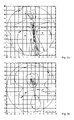
- FIG. 1 a is a cylinder contour map of the unwanted astigmatism of a first prior art progressive addition lens.
- FIG. 1 b is a power contour map of the lens of FIG. 1 a.
- FIG. 2 a is a cylinder contour map of the unwanted astigmatism of a second prior art progressive addition lens.
- FIG. 2 b is a power contour map of the lens of FIG. 2 a.
- FIG. 3 a is a cylinder contour map of the unwanted astigmatism of a first lens of the invention.
- FIG. 3 b is a power contour map of the lens of FIG. 3 a.
- FIG. 4 a is a cylinder contour map of the unwanted astigmatism of a second lens of the invention.
- FIG. 4 b is a power contour map of the lens of FIG. 4 a.
- the present invention provides lenses, and methods for their design and manufacture, which are suitable for use by pre-presbyopic individuals.
- pre-presbyope or “pre-presbyopic individual” is meant a person whose near vision acuity is diminishing, but who does not yet need near vision correction of more than about 0.75 diopters.
- the lenses of the invention are non-conic, aspheric lenses having substantially no noticeable unwanted astigmatism. These lenses are provided by applying localized alterations to a progressive addition surface.
- the invention provides a method for designing a lens, comprising, consisting essentially of, and consisting of: a.) designing a first surface that is a progressive addition surface P(x,y) using a base spherical surface P s (x,y); b.) expressing the first surface P(x,y) as a plurality of sag values P o (x,y); c.) altering locally one or more of the plurality of sag values P o (x,y) to provide a second surface N(x,y); d.) adding the second surface N(x,y) to the base spherical surface P s (x,y) to obtain a non-conic aspheric surface having a maximum unwanted astigmatism between about 50% and 60% of the non-conic surface's add power.
- the invention provides lenses made in accordance with this method.
- lens is meant any ophthalmic lens including, without limitation, a spectacle, contact, intraocular lens and the like.
- the lens of the invention is a spectacle lens.
- sin value is meant the absolute value of the z-axis distance between a point on a surface located at coordinates (x, y) and a corresponding point on a reference plane.
- the z-axis is the axis orthogonal to the x-y plane.
- non-conic, aspheric surface is meant a continuous, aspheric surface having zones for distance and near viewing, and a zone of increasing dioptric power connecting the distance and near zones wherein the surface's add power is between about 0.25 diopters and 0.75 diopters and the maximum, unwanted astigmatism of the surface is less than or equal to about 0.5 diopters.
- the distance vision zone curvature will be less than that of the near zone curvature and if the non-conic, aspheric surface is the lens' concave surface, the distance curvature will be greater than that of the near zone.
- unwanted astigmatism is meant astigmatism that is undesirable and is introduced or caused by the lens surface and is located anywhere on the portion of the lens' surface that is accessed by the wearer's eye when the wearer is viewing distant, intermediate, or near objects. Typically, an individual will experience image distortions that are noticeable when the unwanted astigmatism is greater than about 0.50 diopter.
- a first progressive addition surface is provided by any convenient optical design method.
- the surface, P(x,y) may be a progressive surface or a surface that is the result of combining one or more progressive and regressive surfaces.
- progressive surface or “progressive addition surface” is meant a continuous, aspheric surface having zones of distance and near vision and a zone of increasing dioptric power connecting the distance and near zones wherein the surface's add power is greater than about 0.75 diopters and the maximum, unwanted astigmatism is greater than about 0.5 diopters.
- the distance zone curvature will be less than that of the near zone and if the progressive surface is the lens' concave surface the distance curvature will be greater than that of the near zone.
- regressive surface is meant a continuous, aspheric surface having zones of distance and near vision and a zone of decreasing dioptric power connecting the distance and near zones and wherein the surface's add power is greater than about 0.75 diopters and the maximum, unwanted astigmatism is greater than about 0.5 diopters.
- the distance zone curvature will be greater than that of the near zone and if the regressive surface is the lens' concave surface the distance curvature will be less than that of the near zone.
- designing of the first progressive surface, P(x,y), preferably is carried out using a method that divides the surface into a number of sections and provides a curved surface equation for each area as disclosed, for example, in U.S. Pat. No. 5,886,766 incorporated herein in its entirety by reference.
- Optimization of the surface may be carried out by any convenient method. Additional properties of a specific lens wearer may be introduced into the design optimization process including, without limitation, variations in the pupil diameter of about 1.5 to about 7 mm, image convergence at a point about 25 to about 28 mm behind the front vertex of the surface, pantoscopic tilt of about 7 to about 20 degrees and the like, and combinations thereof.
- the distance and near vision powers for the progressive surface design are selected so that powers of the lens are those needed to correct the lens wearer's visual acuity.
- the dioptric add power for the surfaces will typically be about +0.25 to about +0.75 diopter, preferably between +0.50 to about +0.75 diopter, and most preferably 0.63 diopter. Generally, the distance curvature of the progressive surfaces will be within about 0.25 to about 8.50 diopters.
- the first progressive surface, P(x, y), is then expressed as a plurality of sag values.
- the sag values are calculated by subtracting P(x,y) from the base spherical surface P s (x, y), with a curvature equal to the distance curvature or base curvature, to yield the surface's sag values P o (x,y).
- weighting function W may be used. Selection of the weighting function to be used will depend upon the location, size and shape of the area to be altered.
- the portion of the optic to be altered may be centrally or peripherally located and may be a localized or broad area of a given shape, such as a ring-shaped area.
- W is multiplied by A in Equation I
- the alteration is maximal at Y o and Y o .
- large values of ⁇ x and ⁇ y are used to enable smooth gradients in the transition area.
- alteration function may be used to change the progressive surface depending on the needs the design must fulfill and, thus, the alteration function selected will depend upon the type of alterations desired to be made to the surface and the location at which the alteration is to be made.
- the combined use of he weighting and altering function ensures a smooth blending of the altered and unaltered portions of the optic. Examples of suitable functions include, without limitation, the following.
- a Aspheric ⁇ ( x , y ) c ⁇ S 2 1 + 1 - ( K + 1 ) ⁇ c 2 ⁇ S 2 + A 1 ⁇ S 4 + A 2 ⁇ S 6 + A 3 ⁇ S 8 + A 4 ⁇ S 10 ( V ) wherein c is the inverse radius of curvature;
- the resulting surface may be smoothed by any suitable fitting technique to eliminate curvature discontinuities that result in localized power changes of greater than about 0.05 diopters.
- Any known technique may be used including, without limitation, fitting using polynomial, splines and the like.
- the alteration and weighting functions are selected so that any discontinuities introduced into the resultant surface can be smoothed.
- the resulting non-conic, aspheric surface will not change substantially from the first surface in the distance, near or prism powers provided the alteration is performed within the constraints outlined above. However, if significant changes do occur, appropriate compensations in power may be incorporated into a complementary surface of the lens to offset the changes. Accordingly, other surfaces designed to adapt the lens to the ophthalmic prescription of the lens wearer may be used in combination with, or addition to, the optimized non-conic, aspheric surface. Additionally, the individual surfaces of the lens may have a spherical or aspherical distance vision zone. Further, combinations of any of the above variations may be used.
- the lens of the invention has as its convex surface the surface of the invention and a complementary concave surface, which concave surface corrects the wearer's astigmatism and prism.
- the convex surface preferably has a channel length of about 10 to about 22 mm.
- the surface has an aspherical distance zone which is aspherized to provide additional plus power to the surface of up to about 2.00 diopters, preferably up to about 1.00 diopters, more preferably up to about 0.50 diopters.
- Aspherization may be outside of a circle centered at the fitting point having a radius of about 10 mm, preferably about 15 mm, more preferably about 20 mm
- the lenses of the invention may be constructed of any known material suitable for production of ophthalmic lenses. Such materials are either commercially available or methods for their production are known. Further, the lenses may be produced by any conventional lens fabrication technique including, without limitation, grinding, whole lens casting, molding, thermoforming, laminating, surface casting, or combinations thereof.
- the convex progressive surface of a commercially available progressive lens sold under the brand name Varilux COMFORTTM having a distance curvature of 95.2 mm and an add power of 1.50 D was measured using a coordinate measuring machine to obtain its sag values.
- the sag values were scaled to produce a distance curvature of 94.5 mm and 0.63 D add power.
- the contour plots for cylinder and mean power are shown in FIGS. 1 a . and 1 b .
- the corridor length was 12.26 mm, and the maximum unwanted astigmatism was 0.63 D as shown in Table 1.
- the ratio of astigmatism to add power was 1.00.
- the convex and concave surfaces of a commercially available progressive lens sold under the brand name DEFINITYTM having a distance curvature 103.3 mm and an add power 1.50 D was measured using a coordinate measuring machine to obtain its sag values.
- the sag values were scaled to produce a distance curvature of 105.4 mm and 0.63 D add power.
- the contour plots for cylinder and mean power are shown in FIGS. 2 a . and 2 b .
- the corridor length was 13.09 mm, and the maximum unwanted astigmatism was 0.42 D as shown in Table 1.
- the ratio of astigmatism to add power was 0.67.
- a convex progressive surface was designed using a material with a refractive index of 1.498.
- the lens' base curve was 105.9 mm and the add power was 0.63 diopters.
- a two-step alteration was carried out first using a first toric alteration function and constant weighting function followed by using a second toric alteration function and weighting function with the constants listed below using Equations (I), (II), and (III):
- FIGS. 3 a . and b The contour plots for cylinder and mean power of the resulting non-conic, aspheric surface are shown in FIGS. 3 a . and b .
- the corridor length was 13.57 mm, and the maximum unwanted astigmatism was 0.32 D as shown in Table 1.
- the ratio of astigmatism to add power was 0.51.
- a convex progressive surface was designed using a material with a refractive index of 1.498.
- the lens' base curve was 105.9 mm and the add power was 0.63 diopters.
- a toric alteration function, A and constant weighting function with the constants listed below was used to create a non-conic, aspheric surface using Equations (I), (II) and (III).
- FIGS. 4 a . and b The contour plots for cylinder and mean power for the resulting non-conic, aspheric surface are shown in FIGS. 4 a . and b.
- the corridor length was 11.99 mm, and the maximum unwanted astigmatism was 0.38D as shown in Table 1.
- the ratio of astigmatism to add is 0.60.
Abstract
Description
N(x, y)=P o(x, y)+A(x, y).W(x, y) (I)
- wherein A is an altering function; and
- W is a weighting function.
In the next step, non-conic aspheric surface N(x,y) is added to base spherical surface Ps(x, y) to yield the altered non-conic, aspheric surface of the invention.
wherein, X0 and Y0 correspond to the coordinates where the alteration is going to be maximal:
- σx and σy are the standard deviations of the x and y values of the distribution; and
- ρ is the correlation coefficient between x and y values.
wherein Xo=x.Cos θ−y.Sin θ;
- Y0=y.Cos θ−x.Sin θ;
- r1 is the large radius of curvature;
- r2 is the small radius of curvature; and
- θ is the orientation of the large axis.
wherein Xo=x.Cos θ−y.Sin θ;
- Yo=y.Cos θ−x.Sin θ;
- r1 is the large radius of curvature;
- r2 is the small radius of curvature;
- θ is the orientation of the large axis;
- Ai is an aspheric term; and
- S2=x2+y2.
wherein c is the inverse radius of curvature;
- S2=x2+y2;
- K is a conic constant; and
- Ai is an aspheric term.
A 1(x, y)=1.30×A Toric(x, y,10000,5000,45)
W 1(x, y)=1.00
and
A 2(x, y)=−1.50×A Toric(x, y,10000,5000,90)
W 2(x, y)=W eight(x, y,0,60,100,20,0)
A(x, y)=A Toric(x, y,10000,3000,45)
W(x, y)=1.00
| TABLE 1 | ||||||
| Optical | ||||||
| Parameter | Lens 1 | |
Lens 3 | Lens 4 | ||
| Add Power (D) | 0.63 | 0.63 | 0.63 | 0.63 | ||
| Reading Cyl. | 25.22 | 52.00 | 46.00 | 46.00 | ||
| Width (mm) | ||||||
| Reading Power | 17.42 | 17.72 | 15.07 | 18.78 | ||
| Width (mm) | ||||||
| Corridor Length | 12.26 | 13.09 | 13.57 | 11.99 | ||
| (mm) | ||||||
| Max. Astig. (D) | 0.63 | 0.42 | 0.32 | 0.38 | ||
| Ratio Max | 1.00 | 0.67 | 0.51 | 0.60 | ||
| Astig./Add Power | ||||||
Claims (22)
N(x, y)=P o(x, y)+A(x, y).W(x, y)
Priority Applications (6)
| Application Number | Priority Date | Filing Date | Title |
|---|---|---|---|
| US10/978,165 US7159983B2 (en) | 2004-10-29 | 2004-10-29 | Multifocal lenses for pre-presbyopic individuals |
| TW094137855A TW200626989A (en) | 2004-10-29 | 2005-10-28 | Multifocal lenses for pre-presbyopic individuals |
| PCT/EP2005/013400 WO2006045642A1 (en) | 2004-10-29 | 2005-10-28 | Multifocal lenses for pre-presbyopic individuals |
| MYPI20055112A MY143215A (en) | 2004-10-29 | 2005-10-28 | Multifocal lenses for pre-presbyopic individuals |
| EP05813901A EP1805550A1 (en) | 2004-10-29 | 2005-10-28 | Multifocal lenses for pre-presbyopic individuals |
| JP2007538370A JP2008518255A (en) | 2004-10-29 | 2005-10-28 | Multifocal lens for pre-presbyopia |
Applications Claiming Priority (1)
| Application Number | Priority Date | Filing Date | Title |
|---|---|---|---|
| US10/978,165 US7159983B2 (en) | 2004-10-29 | 2004-10-29 | Multifocal lenses for pre-presbyopic individuals |
Publications (2)
| Publication Number | Publication Date |
|---|---|
| US20060092375A1 US20060092375A1 (en) | 2006-05-04 |
| US7159983B2 true US7159983B2 (en) | 2007-01-09 |
Family
ID=35744784
Family Applications (1)
| Application Number | Title | Priority Date | Filing Date |
|---|---|---|---|
| US10/978,165 Active 2024-12-15 US7159983B2 (en) | 2004-10-29 | 2004-10-29 | Multifocal lenses for pre-presbyopic individuals |
Country Status (6)
| Country | Link |
|---|---|
| US (1) | US7159983B2 (en) |
| EP (1) | EP1805550A1 (en) |
| JP (1) | JP2008518255A (en) |
| MY (1) | MY143215A (en) |
| TW (1) | TW200626989A (en) |
| WO (1) | WO2006045642A1 (en) |
Cited By (35)
| Publication number | Priority date | Publication date | Assignee | Title |
|---|---|---|---|---|
| US20060095128A1 (en) * | 2004-11-02 | 2006-05-04 | Blum Ronald D | Electro-active intraocular lenses |
| US20070258039A1 (en) * | 1999-07-02 | 2007-11-08 | Duston Dwight P | Spectacle frame bridge housing electronics for electro-active spectacle lenses |
| US20080002150A1 (en) * | 1999-07-02 | 2008-01-03 | Blum Ronald D | Static progressive surface region in optical communication with a dynamic optic |
| US20080106633A1 (en) * | 2002-03-13 | 2008-05-08 | Blum Ronald D | Electro-optic lens with integrated components for varying refractive properties |
| US20080316425A1 (en) * | 1999-07-02 | 2008-12-25 | Blum Ronald D | System, apparatus, and method for correcting vision using an electro-active lens |
| US20090033863A1 (en) * | 2007-02-23 | 2009-02-05 | Blum Ronald D | Ophthalmic dynamic aperture |
| US20090091818A1 (en) * | 2007-10-05 | 2009-04-09 | Haddock Joshua N | Electro-active insert |
| US20090103044A1 (en) * | 1999-07-02 | 2009-04-23 | Duston Dwight P | Spectacle frame bridge housing electronics for electro-active spectacle lenses |
| US20090115961A1 (en) * | 2006-06-23 | 2009-05-07 | Pixeloptics Inc. | Electronic adapter for electro-active spectacle lenses |
| US20090153794A1 (en) * | 2007-12-14 | 2009-06-18 | Iyer Venkatramani S | Refractive-diffractive multifocal lens |
| US20090195749A1 (en) * | 1999-07-02 | 2009-08-06 | Blum Ronald D | Electro-optic lens with integrated components for varying refractive properties |
| US20090279050A1 (en) * | 2008-03-25 | 2009-11-12 | Mcginn Joseph Thomas | Electro-optic lenses for correction of higher order aberrations |
| US7775660B2 (en) | 1999-07-02 | 2010-08-17 | E-Vision Llc | Electro-active ophthalmic lens having an optical power blending region |
| US20100271588A1 (en) * | 2006-05-03 | 2010-10-28 | Pixeloptics, Inc. | Electronic eyeglass frame |
| US20110007266A1 (en) * | 2007-03-29 | 2011-01-13 | Pixeloptics, Inc. | Multifocal lens having a progressive optical power region and a discontinuity |
| US7883206B2 (en) | 2007-03-07 | 2011-02-08 | Pixeloptics, Inc. | Multifocal lens having a progressive optical power region and a discontinuity |
| US7926940B2 (en) | 2007-02-23 | 2011-04-19 | Pixeloptics, Inc. | Advanced electro-active optic device |
| WO2011093929A1 (en) | 2010-01-29 | 2011-08-04 | Indizen Optical Technologies, S.L. | Lens with continuous power gradation |
| US8641191B2 (en) | 1999-07-02 | 2014-02-04 | E-Vision, Llc | Static progressive surface region in optical communication with a dynamic optic |
| US8915588B2 (en) | 2004-11-02 | 2014-12-23 | E-Vision Smart Optics, Inc. | Eyewear including a heads up display |
| US9122083B2 (en) | 2005-10-28 | 2015-09-01 | E-Vision Smart Optics, Inc. | Eyewear docking station and electronic module |
| US9155614B2 (en) | 2007-01-22 | 2015-10-13 | E-Vision Smart Optics, Inc. | Flexible dynamic electro-active lens |
| US9335563B2 (en) | 2012-08-31 | 2016-05-10 | Amo Groningen B.V. | Multi-ring lens, systems and methods for extended depth of focus |
| US9801709B2 (en) | 2004-11-02 | 2017-10-31 | E-Vision Smart Optics, Inc. | Electro-active intraocular lenses |
| US10599006B2 (en) | 2016-04-12 | 2020-03-24 | E-Vision Smart Optics, Inc. | Electro-active lenses with raised resistive bridges |
| US10613355B2 (en) | 2007-05-04 | 2020-04-07 | E-Vision, Llc | Moisture-resistant eye wear |
| US10624735B2 (en) | 2016-02-09 | 2020-04-21 | Amo Groningen B.V. | Progressive power intraocular lens, and methods of use and manufacture |
| US11061252B2 (en) | 2007-05-04 | 2021-07-13 | E-Vision, Llc | Hinge for electronic spectacles |
| US11156853B2 (en) | 2017-06-28 | 2021-10-26 | Amo Groningen B.V. | Extended range and related intraocular lenses for presbyopia treatment |
| US11262598B2 (en) | 2017-06-28 | 2022-03-01 | Amo Groningen, B.V. | Diffractive lenses and related intraocular lenses for presbyopia treatment |
| US11327210B2 (en) | 2017-06-30 | 2022-05-10 | Amo Groningen B.V. | Non-repeating echelettes and related intraocular lenses for presbyopia treatment |
| US11397367B2 (en) | 2016-04-12 | 2022-07-26 | E-Vision Smart Optics, Inc. | Electro-active lenses with raised resistive bridges |
| US11497599B2 (en) | 2017-03-17 | 2022-11-15 | Amo Groningen B.V. | Diffractive intraocular lenses for extended range of vision |
| US11523897B2 (en) | 2017-06-23 | 2022-12-13 | Amo Groningen B.V. | Intraocular lenses for presbyopia treatment |
| US11844689B2 (en) | 2019-12-30 | 2023-12-19 | Amo Groningen B.V. | Achromatic lenses and lenses having diffractive profiles with irregular width for vision treatment |
Families Citing this family (17)
| Publication number | Priority date | Publication date | Assignee | Title |
|---|---|---|---|---|
| US20090164008A1 (en) * | 2007-12-21 | 2009-06-25 | Xin Hong | Lens surface with combined diffractive, toric, and aspheric components |
| FR2956222B1 (en) * | 2010-02-09 | 2012-07-27 | Essilor Int | PROGRESSIVE MULTIFOCAL OPHTHALMIC LENS |
| FR2956223B1 (en) * | 2010-02-09 | 2012-04-13 | Essilor Int | PROGRESSIVE MULTIFOCAL OPHTHALMIC LENS |
| JP5872785B2 (en) * | 2011-04-07 | 2016-03-01 | イーエイチエス レンズ フィリピン インク | Progressive power lens design method |
| JP6095271B2 (en) | 2012-03-05 | 2017-03-15 | イーエイチエス レンズ フィリピン インク | Lens set, lens design method, and lens manufacturing method |
| EP2642332B1 (en) * | 2012-03-23 | 2015-05-06 | Essilor International (Compagnie Générale d'Optique) | A progressive addition lens for a wearer |
| US10048512B2 (en) * | 2016-10-08 | 2018-08-14 | eyeBrain, Medical, Inc. | Low-convergence spectacles |
| US10048511B2 (en) | 2016-10-08 | 2018-08-14 | eyeBrain, Medical, Inc. | Eye-strain reducing lens |
| US10338409B2 (en) * | 2016-10-09 | 2019-07-02 | eyeBrain Medical, Inc. | Lens with off-axis curvature center |
| US10420467B2 (en) | 2017-09-05 | 2019-09-24 | eyeBrain Medical, Inc. | Method and system for measuring binocular alignment |
| US11589745B2 (en) | 2017-09-05 | 2023-02-28 | Neurolens, Inc. | Method and system for measuring binocular alignment |
| US11360329B2 (en) | 2017-12-31 | 2022-06-14 | Neurolens, Inc. | Negative power eye-strain reducing lens |
| US10921614B2 (en) | 2017-12-31 | 2021-02-16 | Neurolens, Inc. | Low-convergence negative power spectacles |
| US10908434B2 (en) | 2018-01-01 | 2021-02-02 | Neurolens, Inc. | Negative power lens with off-axis curvature center |
| US10319154B1 (en) * | 2018-07-20 | 2019-06-11 | The University Of North Carolina At Chapel Hill | Methods, systems, and computer readable media for dynamic vision correction for in-focus viewing of real and virtual objects |
| US11156854B2 (en) * | 2019-08-02 | 2021-10-26 | Horizons Optical, S.L.U. | Progressive ophthalmic lens |
| US11838495B1 (en) | 2019-09-13 | 2023-12-05 | Apple Inc. | Electronic devices with vision correcting displays |
Citations (4)
| Publication number | Priority date | Publication date | Assignee | Title |
|---|---|---|---|---|
| US5715032A (en) * | 1996-03-19 | 1998-02-03 | Optical Radiation Corporation | Progressive addition power ophthalmic lens |
| US6000798A (en) * | 1997-10-06 | 1999-12-14 | Innotech Inc. | Ophthalmic optic devices |
| US6106118A (en) * | 1999-09-05 | 2000-08-22 | Johnson & Johnson Vision Products, Inc. | Progressive addition lenses |
| US20050122470A1 (en) * | 2003-12-03 | 2005-06-09 | Sola International Holdings Ltd. | Shaped non-corrective eyewear lenses and methods for providing same |
Family Cites Families (2)
| Publication number | Priority date | Publication date | Assignee | Title |
|---|---|---|---|---|
| JP3757682B2 (en) * | 1998-06-12 | 2006-03-22 | セイコーエプソン株式会社 | Progressive power lens design method |
| JP3825654B2 (en) * | 2000-05-22 | 2006-09-27 | Hoya株式会社 | Ophthalmic optical system simulation method and apparatus |
-
2004
- 2004-10-29 US US10/978,165 patent/US7159983B2/en active Active
-
2005
- 2005-10-28 JP JP2007538370A patent/JP2008518255A/en active Pending
- 2005-10-28 MY MYPI20055112A patent/MY143215A/en unknown
- 2005-10-28 EP EP05813901A patent/EP1805550A1/en not_active Withdrawn
- 2005-10-28 WO PCT/EP2005/013400 patent/WO2006045642A1/en active Application Filing
- 2005-10-28 TW TW094137855A patent/TW200626989A/en unknown
Patent Citations (4)
| Publication number | Priority date | Publication date | Assignee | Title |
|---|---|---|---|---|
| US5715032A (en) * | 1996-03-19 | 1998-02-03 | Optical Radiation Corporation | Progressive addition power ophthalmic lens |
| US6000798A (en) * | 1997-10-06 | 1999-12-14 | Innotech Inc. | Ophthalmic optic devices |
| US6106118A (en) * | 1999-09-05 | 2000-08-22 | Johnson & Johnson Vision Products, Inc. | Progressive addition lenses |
| US20050122470A1 (en) * | 2003-12-03 | 2005-06-09 | Sola International Holdings Ltd. | Shaped non-corrective eyewear lenses and methods for providing same |
Cited By (88)
| Publication number | Priority date | Publication date | Assignee | Title |
|---|---|---|---|---|
| US8727531B2 (en) | 1999-07-02 | 2014-05-20 | E-Vision, Llc | Electro-active opthalmic lens having an optical power blending region |
| US9411173B1 (en) | 1999-07-02 | 2016-08-09 | E-Vision Smart Optics, Inc. | Electro-active opthalmic lens having an optical power blending region |
| US20080002150A1 (en) * | 1999-07-02 | 2008-01-03 | Blum Ronald D | Static progressive surface region in optical communication with a dynamic optic |
| US8047651B2 (en) | 1999-07-02 | 2011-11-01 | E-Vision Inc. | Electro-active opthalmic lens having an optical power blending region |
| US8029134B2 (en) | 1999-07-02 | 2011-10-04 | E-Vision, Llc | System, apparatus, and method for correcting vision using an electro-active lens |
| US9323101B2 (en) | 1999-07-02 | 2016-04-26 | E-Vision Smart Optics, Inc. | Electro-active opthalmic lens having an optical power blending region |
| US20070258039A1 (en) * | 1999-07-02 | 2007-11-08 | Duston Dwight P | Spectacle frame bridge housing electronics for electro-active spectacle lenses |
| US20090103044A1 (en) * | 1999-07-02 | 2009-04-23 | Duston Dwight P | Spectacle frame bridge housing electronics for electro-active spectacle lenses |
| US20080316425A1 (en) * | 1999-07-02 | 2008-12-25 | Blum Ronald D | System, apparatus, and method for correcting vision using an electro-active lens |
| US9500883B2 (en) | 1999-07-02 | 2016-11-22 | E-Vision Smart Optics, Inc. | Electro-active opthalmic lens having an optical power blending region |
| US20090195749A1 (en) * | 1999-07-02 | 2009-08-06 | Blum Ronald D | Electro-optic lens with integrated components for varying refractive properties |
| US8641191B2 (en) | 1999-07-02 | 2014-02-04 | E-Vision, Llc | Static progressive surface region in optical communication with a dynamic optic |
| US7731358B2 (en) | 1999-07-02 | 2010-06-08 | E-Vision Llc | System, apparatus, and method for correcting vision using an electro-active lens |
| US7775660B2 (en) | 1999-07-02 | 2010-08-17 | E-Vision Llc | Electro-active ophthalmic lens having an optical power blending region |
| US8333470B2 (en) | 1999-07-02 | 2012-12-18 | E-Vision Llc | Electro-active opthalmic lens having an optical power blending region |
| US20080106633A1 (en) * | 2002-03-13 | 2008-05-08 | Blum Ronald D | Electro-optic lens with integrated components for varying refractive properties |
| US20060095128A1 (en) * | 2004-11-02 | 2006-05-04 | Blum Ronald D | Electro-active intraocular lenses |
| US10379575B2 (en) | 2004-11-02 | 2019-08-13 | E-Vision Smart Optics, Inc. | Eyewear including a remote control camera and a docking station |
| US9124796B2 (en) | 2004-11-02 | 2015-09-01 | E-Vision Smart Optics, Inc. | Eyewear including a remote control camera |
| US11822155B2 (en) | 2004-11-02 | 2023-11-21 | E-Vision Smart Optics, Inc. | Eyewear including a remote control camera |
| US10795411B2 (en) | 2004-11-02 | 2020-10-06 | E-Vision Smart Optics, Inc. | Eyewear including a remote control camera and a docking station |
| US10729539B2 (en) | 2004-11-02 | 2020-08-04 | E-Vision Smart Optics, Inc. | Electro-chromic ophthalmic devices |
| US8931896B2 (en) | 2004-11-02 | 2015-01-13 | E-Vision Smart Optics Inc. | Eyewear including a docking station |
| US8915588B2 (en) | 2004-11-02 | 2014-12-23 | E-Vision Smart Optics, Inc. | Eyewear including a heads up display |
| US11144090B2 (en) | 2004-11-02 | 2021-10-12 | E-Vision Smart Optics, Inc. | Eyewear including a camera or display |
| US10092395B2 (en) | 2004-11-02 | 2018-10-09 | E-Vision Smart Optics, Inc. | Electro-active lens with crossed linear electrodes |
| US11262796B2 (en) | 2004-11-02 | 2022-03-01 | E-Vision Smart Optics, Inc. | Eyewear including a detachable power supply and display |
| US10172704B2 (en) | 2004-11-02 | 2019-01-08 | E-Vision Smart Optics, Inc. | Methods and apparatus for actuating an ophthalmic lens in response to ciliary muscle motion |
| US10159563B2 (en) | 2004-11-02 | 2018-12-25 | E-Vision Smart Optics, Inc. | Eyewear including a detachable power supply and a display |
| US10126569B2 (en) | 2004-11-02 | 2018-11-13 | E-Vision Smart Optics Inc. | Flexible electro-active lens |
| US8778022B2 (en) | 2004-11-02 | 2014-07-15 | E-Vision Smart Optics Inc. | Electro-active intraocular lenses |
| US10852766B2 (en) | 2004-11-02 | 2020-12-01 | E-Vision Smart Optics, Inc. | Electro-active elements with crossed linear electrodes |
| US9801709B2 (en) | 2004-11-02 | 2017-10-31 | E-Vision Smart Optics, Inc. | Electro-active intraocular lenses |
| US11422389B2 (en) | 2004-11-02 | 2022-08-23 | E-Vision Smart Optics, Inc. | Eyewear including a remote control camera |
| US10114235B2 (en) | 2005-10-28 | 2018-10-30 | E-Vision Smart Optics, Inc. | Eyewear docking station and electronic module |
| US9122083B2 (en) | 2005-10-28 | 2015-09-01 | E-Vision Smart Optics, Inc. | Eyewear docking station and electronic module |
| US8337014B2 (en) | 2006-05-03 | 2012-12-25 | Pixeloptics, Inc. | Electronic eyeglass frame |
| US20100271588A1 (en) * | 2006-05-03 | 2010-10-28 | Pixeloptics, Inc. | Electronic eyeglass frame |
| US8408699B2 (en) | 2006-06-23 | 2013-04-02 | Pixeloptics, Inc. | Electro-active spectacle lenses |
| US20090115961A1 (en) * | 2006-06-23 | 2009-05-07 | Pixeloptics Inc. | Electronic adapter for electro-active spectacle lenses |
| US20110228212A1 (en) * | 2006-06-23 | 2011-09-22 | Pixeloptics, Inc. | Electro-Active Spectacle Lenses |
| US7971994B2 (en) | 2006-06-23 | 2011-07-05 | Pixeloptics, Inc. | Electro-active spectacle lenses |
| US11474380B2 (en) | 2007-01-22 | 2022-10-18 | E-Vision Smart Optics, Inc. | Flexible electro-active lens |
| US9155614B2 (en) | 2007-01-22 | 2015-10-13 | E-Vision Smart Optics, Inc. | Flexible dynamic electro-active lens |
| US8215770B2 (en) | 2007-02-23 | 2012-07-10 | E-A Ophthalmics | Ophthalmic dynamic aperture |
| US20090033863A1 (en) * | 2007-02-23 | 2009-02-05 | Blum Ronald D | Ophthalmic dynamic aperture |
| US7926940B2 (en) | 2007-02-23 | 2011-04-19 | Pixeloptics, Inc. | Advanced electro-active optic device |
| US20110194069A1 (en) * | 2007-03-07 | 2011-08-11 | Pixeloptics, Inc. | Multifocal Lens Having a Progressive Optical Power Region and Discontinuity |
| US8434865B2 (en) | 2007-03-07 | 2013-05-07 | Pixeloptics, Inc. | Multifocal lens having a progressive optical power region and a discontinuity |
| US7883206B2 (en) | 2007-03-07 | 2011-02-08 | Pixeloptics, Inc. | Multifocal lens having a progressive optical power region and a discontinuity |
| US8197063B2 (en) | 2007-03-07 | 2012-06-12 | Pixeloptics, Inc. | Refractive-diffractive multifocal lens |
| US8308295B2 (en) | 2007-03-07 | 2012-11-13 | Pixeloptics, Inc. | Multifocal lens having a progressive optical power region and discontinuity |
| US8662665B2 (en) | 2007-03-07 | 2014-03-04 | Pixeloptics, Inc. | Refractive-diffractive multifocal lens |
| US8092016B2 (en) | 2007-03-29 | 2012-01-10 | Pixeloptics, Inc. | Multifocal lens having a progressive optical power region and a discontinuity |
| US9033494B2 (en) | 2007-03-29 | 2015-05-19 | Mitsui Chemicals, Inc. | Multifocal lens having a progressive optical power region and a discontinuity |
| US20110007266A1 (en) * | 2007-03-29 | 2011-01-13 | Pixeloptics, Inc. | Multifocal lens having a progressive optical power region and a discontinuity |
| US8708483B2 (en) | 2007-05-04 | 2014-04-29 | Pixeloptics, Inc. | Electronic eyeglass frame |
| US9028062B2 (en) | 2007-05-04 | 2015-05-12 | Mitsui Chemicals, Inc. | Electronic eyeglass frame |
| US11061252B2 (en) | 2007-05-04 | 2021-07-13 | E-Vision, Llc | Hinge for electronic spectacles |
| US10613355B2 (en) | 2007-05-04 | 2020-04-07 | E-Vision, Llc | Moisture-resistant eye wear |
| US11586057B2 (en) | 2007-05-04 | 2023-02-21 | E-Vision, Llc | Moisture-resistant eye wear |
| US20090091818A1 (en) * | 2007-10-05 | 2009-04-09 | Haddock Joshua N | Electro-active insert |
| US20090153794A1 (en) * | 2007-12-14 | 2009-06-18 | Iyer Venkatramani S | Refractive-diffractive multifocal lens |
| US7883207B2 (en) | 2007-12-14 | 2011-02-08 | Pixeloptics, Inc. | Refractive-diffractive multifocal lens |
| US20090279050A1 (en) * | 2008-03-25 | 2009-11-12 | Mcginn Joseph Thomas | Electro-optic lenses for correction of higher order aberrations |
| US8154804B2 (en) | 2008-03-25 | 2012-04-10 | E-Vision Smart Optics, Inc. | Electro-optic lenses for correction of higher order aberrations |
| US10197815B2 (en) | 2008-05-13 | 2019-02-05 | Amo Groningen B.V. | Multi-ring lens, systems and methods for extended depth of focus |
| WO2011093929A1 (en) | 2010-01-29 | 2011-08-04 | Indizen Optical Technologies, S.L. | Lens with continuous power gradation |
| US8042941B2 (en) | 2010-01-29 | 2011-10-25 | Indizen Optical Technologies, S.I. | Lens with continuous power gradation |
| US20110187993A1 (en) * | 2010-01-29 | 2011-08-04 | Indizen Optical Technologies, S.I. | Lens with continuous power gradation |
| US10598960B2 (en) | 2012-01-06 | 2020-03-24 | E-Vision Smart Optics, Inc. | Eyewear docking station and electronic module |
| US11487138B2 (en) | 2012-01-06 | 2022-11-01 | E-Vision Smart Optics, Inc. | Eyewear docking station and electronic module |
| US11022815B2 (en) | 2012-08-31 | 2021-06-01 | Amo Groningen B.V. | Multi-ring lens, systems and methods for extended depth of focus |
| US9335563B2 (en) | 2012-08-31 | 2016-05-10 | Amo Groningen B.V. | Multi-ring lens, systems and methods for extended depth of focus |
| US11116624B2 (en) | 2016-02-09 | 2021-09-14 | Amo Groningen B.V. | Progressive power intraocular lens, and methods of use and manufacture |
| US10624735B2 (en) | 2016-02-09 | 2020-04-21 | Amo Groningen B.V. | Progressive power intraocular lens, and methods of use and manufacture |
| US11662642B2 (en) | 2016-04-12 | 2023-05-30 | E-Vision Smart Optics, Inc. | Electro-active lenses with raised resistive bridges |
| US11397367B2 (en) | 2016-04-12 | 2022-07-26 | E-Vision Smart Optics, Inc. | Electro-active lenses with raised resistive bridges |
| US10599006B2 (en) | 2016-04-12 | 2020-03-24 | E-Vision Smart Optics, Inc. | Electro-active lenses with raised resistive bridges |
| US11054714B2 (en) | 2016-04-12 | 2021-07-06 | E-Vision Smart Optics, Inc. | Electro-active lenses with raised resistive bridges |
| US11497599B2 (en) | 2017-03-17 | 2022-11-15 | Amo Groningen B.V. | Diffractive intraocular lenses for extended range of vision |
| US11523897B2 (en) | 2017-06-23 | 2022-12-13 | Amo Groningen B.V. | Intraocular lenses for presbyopia treatment |
| US11156853B2 (en) | 2017-06-28 | 2021-10-26 | Amo Groningen B.V. | Extended range and related intraocular lenses for presbyopia treatment |
| US11573433B2 (en) | 2017-06-28 | 2023-02-07 | Amo Groningen B.V. | Extended range and related intraocular lenses for presbyopia treatment |
| US11262598B2 (en) | 2017-06-28 | 2022-03-01 | Amo Groningen, B.V. | Diffractive lenses and related intraocular lenses for presbyopia treatment |
| US11914229B2 (en) | 2017-06-28 | 2024-02-27 | Amo Groningen B.V. | Diffractive lenses and related intraocular lenses for presbyopia treatment |
| US11327210B2 (en) | 2017-06-30 | 2022-05-10 | Amo Groningen B.V. | Non-repeating echelettes and related intraocular lenses for presbyopia treatment |
| US11844689B2 (en) | 2019-12-30 | 2023-12-19 | Amo Groningen B.V. | Achromatic lenses and lenses having diffractive profiles with irregular width for vision treatment |
Also Published As
| Publication number | Publication date |
|---|---|
| WO2006045642A1 (en) | 2006-05-04 |
| JP2008518255A (en) | 2008-05-29 |
| US20060092375A1 (en) | 2006-05-04 |
| EP1805550A1 (en) | 2007-07-11 |
| TW200626989A (en) | 2006-08-01 |
| MY143215A (en) | 2011-03-31 |
Similar Documents
| Publication | Publication Date | Title |
|---|---|---|
| US7159983B2 (en) | Multifocal lenses for pre-presbyopic individuals | |
| US6709105B2 (en) | Progressive addition lenses | |
| US7318642B2 (en) | Progressive addition lenses with reduced unwanted astigmatism | |
| US6199984B1 (en) | Progressive addition lenses with varying power profiles | |
| CA2375162C (en) | Progressive lens | |
| EP1216432B1 (en) | Progressive lens | |
| US20090290121A1 (en) | Method for determining a set of progressive multifocal ophthalmic lenses | |
| AU2002252366A1 (en) | Progressive addition lenses | |
| US6106118A (en) | Progressive addition lenses | |
| US6260967B1 (en) | Progressive lens | |
| US8608312B2 (en) | Method for determining an aspherization layer for an ophthalmic lens | |
| US6231184B1 (en) | Progressive addition lenses | |
| US8646909B2 (en) | Method for determining, optimizing and producing an ophthalmic lens and set of ophthalmic lenses | |
| US7111937B2 (en) | Spectacle lenses incorporating atoric surfaces | |
| US20140253874A1 (en) | Low distortion eyewear lens with low optical power | |
| AU772399B2 (en) | Progressive lens |
Legal Events
| Date | Code | Title | Description |
|---|---|---|---|
| AS | Assignment |
Owner name: JOHNSON & JOHNSON VISION CARE, INC., FLORIDA Free format text: ASSIGNMENT OF ASSIGNORS INTEREST;ASSIGNORS:MENEZES, EDGAR V.;GERLIGAND, PIERRE-YVES;REEL/FRAME:015700/0281 Effective date: 20050120 |
|
| AS | Assignment |
Owner name: ESSILOR INTERNATIONAL (COMPAGNE GENERALE D'OPTIQUE Free format text: ASSIGNMENT OF ASSIGNORS INTEREST;ASSIGNOR:JOHNSON & JOHNSON VISION CARE, INC.;REEL/FRAME:016848/0236 Effective date: 20050721 |
|
| AS | Assignment |
Owner name: ESSILOR INTERNATIONAL (COMPAGNIE GENERALE D'OPTIQU Free format text: ASSIGNMENT OF ASSIGNORS INTEREST;ASSIGNOR:JOHNSON & JOHNSON VISION CARE, INC.;REEL/FRAME:017314/0505 Effective date: 20050722 |
|
| STCF | Information on status: patent grant |
Free format text: PATENTED CASE |
|
| FPAY | Fee payment |
Year of fee payment: 4 |
|
| FPAY | Fee payment |
Year of fee payment: 8 |
|
| AS | Assignment |
Owner name: ESSILOR INTERNATIONAL, FRANCE Free format text: ASSIGNMENT OF ASSIGNORS INTEREST;ASSIGNOR:ESSILOR INTERNATIONAL (COMPAGNIE GENERALE D'OPTIQUE);REEL/FRAME:045853/0275 Effective date: 20171101 |
|
| MAFP | Maintenance fee payment |
Free format text: PAYMENT OF MAINTENANCE FEE, 12TH YEAR, LARGE ENTITY (ORIGINAL EVENT CODE: M1553) Year of fee payment: 12 |