US7038579B2 - Catalyst detector for vehicle - Google Patents
Catalyst detector for vehicle Download PDFInfo
- Publication number
- US7038579B2 US7038579B2 US10/696,590 US69659003A US7038579B2 US 7038579 B2 US7038579 B2 US 7038579B2 US 69659003 A US69659003 A US 69659003A US 7038579 B2 US7038579 B2 US 7038579B2
- Authority
- US
- United States
- Prior art keywords
- radiator
- catalyst coating
- sensor
- heat exchanger
- detection
- Prior art date
- Legal status (The legal status is an assumption and is not a legal conclusion. Google has not performed a legal analysis and makes no representation as to the accuracy of the status listed.)
- Expired - Fee Related, expires
Links
Images


Classifications
-
- F—MECHANICAL ENGINEERING; LIGHTING; HEATING; WEAPONS; BLASTING
- F01—MACHINES OR ENGINES IN GENERAL; ENGINE PLANTS IN GENERAL; STEAM ENGINES
- F01P—COOLING OF MACHINES OR ENGINES IN GENERAL; COOLING OF INTERNAL-COMBUSTION ENGINES
- F01P11/00—Component parts, details, or accessories not provided for in, or of interest apart from, groups F01P1/00 - F01P9/00
-
- B—PERFORMING OPERATIONS; TRANSPORTING
- B01—PHYSICAL OR CHEMICAL PROCESSES OR APPARATUS IN GENERAL
- B01D—SEPARATION
- B01D53/00—Separation of gases or vapours; Recovering vapours of volatile solvents from gases; Chemical or biological purification of waste gases, e.g. engine exhaust gases, smoke, fumes, flue gases, aerosols
- B01D53/34—Chemical or biological purification of waste gases
- B01D53/74—General processes for purification of waste gases; Apparatus or devices specially adapted therefor
- B01D53/86—Catalytic processes
- B01D53/8671—Removing components of defined structure not provided for in B01D53/8603 - B01D53/8668
- B01D53/8675—Ozone
-
- B—PERFORMING OPERATIONS; TRANSPORTING
- B01—PHYSICAL OR CHEMICAL PROCESSES OR APPARATUS IN GENERAL
- B01D—SEPARATION
- B01D2259/00—Type of treatment
- B01D2259/45—Gas separation or purification devices adapted for specific applications
- B01D2259/455—Gas separation or purification devices adapted for specific applications for transportable use
- B01D2259/4558—Gas separation or purification devices adapted for specific applications for transportable use for being employed as mobile cleaners for ambient air, i.e. the earth's atmosphere
-
- F—MECHANICAL ENGINEERING; LIGHTING; HEATING; WEAPONS; BLASTING
- F01—MACHINES OR ENGINES IN GENERAL; ENGINE PLANTS IN GENERAL; STEAM ENGINES
- F01P—COOLING OF MACHINES OR ENGINES IN GENERAL; COOLING OF INTERNAL-COMBUSTION ENGINES
- F01P11/00—Component parts, details, or accessories not provided for in, or of interest apart from, groups F01P1/00 - F01P9/00
- F01P11/14—Indicating devices; Other safety devices
-
- Y—GENERAL TAGGING OF NEW TECHNOLOGICAL DEVELOPMENTS; GENERAL TAGGING OF CROSS-SECTIONAL TECHNOLOGIES SPANNING OVER SEVERAL SECTIONS OF THE IPC; TECHNICAL SUBJECTS COVERED BY FORMER USPC CROSS-REFERENCE ART COLLECTIONS [XRACs] AND DIGESTS
- Y02—TECHNOLOGIES OR APPLICATIONS FOR MITIGATION OR ADAPTATION AGAINST CLIMATE CHANGE
- Y02A—TECHNOLOGIES FOR ADAPTATION TO CLIMATE CHANGE
- Y02A50/00—TECHNOLOGIES FOR ADAPTATION TO CLIMATE CHANGE in human health protection, e.g. against extreme weather
- Y02A50/20—Air quality improvement or preservation, e.g. vehicle emission control or emission reduction by using catalytic converters
Definitions
- This invention relates to a catalyst detector for a vehicle, and more particularly to a detector provided in a vehicle to detect loss and deterioration of a catalyst coating for decomposing chemical substances such as ozone (O 3 ) in the ambient air.
- ozone decomposing performances of the ozone decomposing devices are subject to change, and decrease with deterioration of catalyst, loss (detachment) of the catalyst coating and the like. Therefore, NMOG credits are supposed to be granted to the vehicles in accordance with ozone decomposing performances thereof measured after 150,000 miles (approx. 241,350 km) of driving. Each manufacturer evaluates ozone decomposing performances after 150,000 miles of driving for each vehicle type and for each vehicle model through testing of various kinds, and submits an application for certification of NMOG credits with the evaluated value or a value lower than the evaluated value to the authority.
- the ozone decomposing device installed in a new vehicle should fulfill the evaluated value of the performance at the time of submitting the application, but the performance could disadvantageously decrease to a value lower than the value declared in the application before 15,000 miles of driving depending on circumstances (e.g., under rough usage).
- the manufacturers of the vehicles should continuously demonstrate the ozone decomposing performance and durability of the ozone decomposing device throughout the effective period of service life so that maintenance and checkup can be timely carried out.
- the manufacturers are required to incorporate an on-board diagnostic (OBD) system for monitoring the performance of the ozone decomposing device in each vehicle they ships, so as to guarantee that appropriate control is being exercised on emissions. Therefore, each manufacturer has been developing such on-board diagnostic systems.
- OBD on-board diagnostic
- the above disclosures refer to methods of detecting loss or deterioration of catalyst coatings using a sensor or the like (as embodied in on-board diagnostic systems), but no specific reference is made to a position of detection (or a location where a sensor is installed) relative to a radiator.
- the inventors named in the present application have discovered that the position of detection relative to a radiator is critical in accurate detection of decrease in performance of the ozone decomposing device.
- the present invention has been made to address the above-discussed disadvantages, and it is an exemplary general object of the present invention to provide a catalyst detector capable of accurately detecting decrease in performance of the ozone decomposing device provided in vehicles.
- a detector is provided in a vehicle equipped with a heat exchanger, and a catalyst coating provided in the heat exchanger decomposes a chemical substance in air passing through the heat exchanger.
- the detector includes a sensor and a control unit.
- the sensor detects a remaining amount of the catalyst coating, and the control unit generates an alarm based upon detection of the sensor.
- a position of detection of the sensor is determined according to a temperature characteristic of the heat exchanger.
- the catalyst coating gradually comes off from a higher-temperature portion to a lower-temperature portion on a surface of the heat exchanger, and when loss of the catalyst coating eventually takes place in the position of detection of the sensor, the control unit determines that the chemical substance decomposing performance has decreased to an insufficient level, and generates an alarm to give a warning to a passenger of the vehicle. Since the position of detection has been determined according to the temperature characteristic of the heat exchanger, the detector can accurately detect the decrease in performance of the catalyst coating without fail.
- the position of detection of the sensor may preferably be determined according to a flow rate of the air passing through the heat exchanger in addition to the temperature characteristic of the heat exchanger, so that the detector can more accurately detect the decrease in performance of the catalyst coating.
- a plurality of positions of detection may be determined respectively, as necessary, for corresponding ranges of flow rates of air passing through the heat exchanger, so that the loss of catalyst coating (i.e., deterioration of the chemical substance decomposing performance) can accurately be detected in an entire range of the possible flow rates of the air passing through the heat exchanger.
- the above heat exchanger may be, but not limited to, a radiator, and the temperature characteristic of the heat exchanger used to determine the position of detection of the sensor may be a temperature distribution of a front surface of the radiator or a time integral of temperature distributions of the front surface of the radiator.
- the temperature distribution of the catalyst coating which serves as an index of susceptibility to coating loss, can be evaluated beforehand from the temperature distribution of the front surface of the radiator.
- the temperature distribution of the front surface of the radiator can easily be measured using an instrument known in the art, such as a thermography.
- the use of a time integral of the temperature distributions makes it possible to make the borders of temperature areas more definite.
- the position of detection of the sensor may be determined so that detection occurs when an amount of decomposition of the chemical substance by an action of the catalyst coating (chemical substance decomposing performance of the catalyst coating) becomes less than a value declared in an application for certification of decomposing performance.
- the amount of decomposition of the chemical substance is less than the threshold predetermined based upon the declared value, it is determined that the catalyst coating has deteriorated to an insufficient level.
- FIG. 1 is an overall view of a vehicle in which one exemplary embodiment of a detector according to the present invention is provided.
- FIG. 2 is an enlarged view of a radiator and peel sensor shown in FIG. 1 , in which (a) shows a perspective view of the radiator, (b) shows a partial enlarged view of the radiator, and (c) shows an enlarged view of the peel sensor illustrated in (b).
- FIG. 3 is a graph showing characteristics of air cleaning credits obtained by testing with a fresh catalyst coating, and those to be declared in an application for certification of the catalyst coating according to a first embodiment of the present invention.
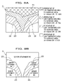
- FIG. 4A is a distribution map illustrating two upper-limit borders of low-temperature areas (in percentage) of a front surface of the radiator, corresponding to the maximum and minimum catalyst retention rates respectively, with the airflow quantity being 1200 m 3 .
- FIG. 4B is a distribution map illustrating an upper-limit border of a low-temperature area (in percentage) of the front surface of the radiator, corresponding to the minimum catalyst retention rate, with the airflow quantity being 300 m 3 .
- FIG. 4C is a distribution map illustrating two upper-limit borders of low-temperature areas (in percentage) of the front surface of the radiator, corresponding to the maximum and minimum catalyst retention rates respectively, with the airflow quantity ranging from 300–1200 m 3 .
- FIG. 5 is a graph showing characteristics of air cleaning credits obtained by testing with a fresh catalyst coating, and those to be declared in an application for certification of the catalyst coating according to a second embodiment of the present invention.
- FIG. 6A is a schematic diagram for explaining detection of loss and deterioration of the catalyst coating using a peel sensor and an airflow sensor when the airflow quantity is 700 m 3 .
- FIG. 6B is a schematic diagram for explaining detection of loss and deterioration of the catalyst coating using a peel sensor and an airflow sensor when the airflow quantity is 500 m 3 .
- FIG. 7A is a schematic diagram for explaining detection of loss and deterioration of the catalyst coating using a peel sensor and an airflow sensor when the airflow quantity is 610 m 3 .
- FIG. 7B is a schematic diagram for explaining detection of loss and deterioration of the catalyst coating using a peel sensor and an airflow sensor when the airflow quantity is 590 m 3 .
- FIG. 8A is a distribution map of temperatures on the front surface of the radiator, used in a third embodiment of the present invention.
- FIG. 8B is a schematic diagram for explaining determination of the position of attachment of the peel sensor.
- FIG. 9 is a schematic diagram showing a general smog-causing environment and a passenger car equipped with an ozone reduction device.
- a heat exchanger exemplified by a radiator 2 , which generally includes a plurality of vertically extending cooling pipes 3 through which coolant for an engine of the passenger car 1 flows downwardly, and a large number of radiating fins 4 fixed between cooling pipes 3 .
- the radiator 2 dissipates heat in the coolant, which is heated in the engine of the passenger car 1 during driving, into air, so that the coolant is maintained constantly at an adequate range of temperature.
- catalyst coating 5 To outer surfaces of the cooling pipes 3 and the radiating fins 4 constituting the radiator 2 is entirely applied, using a bonding agent such as an organic binder (not shown), an ozone reducing catalyst coating 5 (hereinafter referred to as catalyst coating 5 ).
- the catalyst coating 5 serves to decompose ozone (O 3 ) as a chemical substance in the air passing within the radiator 2 between the radiating fins 4 thereof into oxygen (O 2 ), and to reduce ozone in the air thereby cleaning the air (see FIG. 1 ).
- the detector 6 includes a peel sensor 7 embedded in the catalyst coating 5 and fixed on the radiator 2 , a control unit CU for generating an alarm signal based upon a detection value from the peel sensor 7 , and a MIL illumination (hereinafter referred to as MIL M) that is turned on and off based upon the alarm signal from the control unit CU.
- MIL M MIL illumination
- the peel sensor 7 includes a base 7 A made of insulating material and fixed on the outer surface of the cooling pipe 3 in the radiator 2 , and a pair of lead wires 7 A, 7 B each stuck on the base 7 A separately, one on an upper portion thereof, the other on a lower portion thereof.
- the catalyst coating 5 gradually comes off and deteriorates with increase in distance of driving or the like, from the upper portion which is high in temperature, toward the lower portion.
- the resistance between the lead wires 7 A and 7 B changes.
- the peel sensor 7 then outputs a quantity of change in resistance to a controller (not shown), and thereby detects a remaining amount of the catalyst coating 5 .
- the position of detection (attachment) of the peel sensor 7 on the radiator 2 is determined so that detection occurs if an amount of ozone decomposition by an action of the catalyst coating 5 becomes less than a value declared in an application for certification of credits, as will be described later.
- the detector 6 need be provided to accurately detect the loss and deterioration of the catalyst coating 5 .
- the y-axis denotes an air cleaning credit as an index of ozone decomposing performance of the catalyst coating 5 .
- airflow quantity AF the flow quantity AF of air passing through the radiator 2
- AF Fresh 1200 m 3
- ⁇ Fresh 80%
- the airflow quantity AF is designated by a volume (cubic meter) of air passing per unit time in a prescribed mode.
- the air cleaning credit lowers to A/2 (mg/mile), which is used as a value to be declared in an application for certification of NMOG credits for quality assurance of the catalyst coating 5 (see FIG. 3 ).
- the air cleaning credit for the catalyst coating 5 falls within a range between A and A/2, then it is determined that the catalyst coating 5 has not deteriorated but still has sufficient level of performance maintained, and the MIL M in the detector 6 remains turned off as shown in FIG. 3 .
- the air cleaning credit represented immediately before an engine becomes nearly overheated for some reason, e.g., because a malfunction occurs in the radiator 2 , lowers to A/16 (mg/mile) as shown in FIG. 3 , and the airflow quantity AF at that time decreases to AF min 300 m 3 as shown in FIG. 4B .
- the air cleaning credit for the catalyst coating 5 exhibits a value equal to or higher than A/16 and lower than A/2, it is determined that the ozone reducing performance of the catalyst coating 5 has lowered to an insufficient level, and then the MIL M of the detector 6 is lit up (see FIG. 3 ) to give a warning to a passenger.
- the ozone reduction rate ⁇ (%) represented when the airflow quantity AF exhibits the maximum value 1200 m 3 can be obtained from the above Equations (2)–(4) as follows:
- the ozone reduction rate lowers to three fourths (3 ⁇ 4) due to deterioration of the catalyst coating 5 itself, and thus it should be determined by the time when the catalyst retention rate becomes 8.3% (6.25% ⁇ 4/3) that the catalyst coating 5 has come off or deteriorated to a critically low level.
- the catalyst retention rate of the radiator 2 is equivalent to the percentage of a low-temperature area to a surface area (e.g., of the front surface) of the radiator 2 .
- temperature characteristic (temperature distribution) of the front surface of the radiator 2 measured in advance during operation of the passenger car 1 is used to determine the position of attachment of the peel sensor 7 .
- the peel sensor 7 may be attached to a position within an area between two upper-limit borders of the low-temperature areas of which the percentages to the front surface area of the radiator 2 are 8.3% and 50% respectively, so that loss and deterioration of the catalyst coating 5 can be detected accurately.
- the ozone reduction rate lowers to three fourths (3 ⁇ 4) due to deterioration of the catalyst coating 5 itself, and it should thus be determined by the time when the catalyst retention rate becomes 33.3% (25% ⁇ 4/3) or higher that the catalyst coating 5 has come off or deteriorated to a critically low level. Since ⁇ max is more than 100%, calculation of the upper limit of the catalyst retention rate is omitted.
- the peel sensor 7 may be attached to a position within an area between two upper-limit borders of the low-temperature areas of which the percentages to the front surface area of the radiator 2 are 33.3% and 100% respectively, so that loss and deterioration of the catalyst coating 5 can be detected accurately.
- This embodiment utilizes a plurality of peel sensors that make it possible to detect loss and deterioration of a catalyst coating even if the maximum ozone reduction rate represented when the airflow quantity exhibits a maximum value is smaller than the minimum ozone reduction rate represented when the airflow quantity exhibits a minimum value.
- the y-axis denotes an air cleaning credit as in FIG. 3 .
- the air cleaning credit A represented upon testing with a fresh catalyst coating can be obtained from Equation (1) and FIG. 5 as expressed in Equation (2) as above.
- the air cleaning credit lowers to A/8 (mg/mile), which is used as a value to be declared in an application for certification of NMOG credits for quality assurance of the catalyst coating 5 (see FIG. 5 ).
- the air cleaning credit for the catalyst coating falls within a range between A and A/8, then it is determined that the catalyst coating has not deteriorated but still has sufficient level of performance maintained, and the MIL M remains turned off as shown in FIG. 5 .
- the air cleaning credit for the catalyst coating exhibits a value equal to or higher than A/16 and lower than A/8, it is determined that the ozone reducing performance of the catalyst coating has lowered to an insufficient level, and then the MIL M is lit up (see FIG. 5 ) to give a warning to a passenger.
- the ozone reduction rate ⁇ (%) represented when the airflow quantity AF exhibits the maximum value 1200 m 3 can be obtained from the above Equations (2), (7) and (8) as follows:
- the MIL M needs to be lit up when the catalyst retention rate, i.e., percentage of a low-temperature area to the front surface area of the radiator 2 , satisfies Equation (11) as follows: 8.3% ⁇ LTA (%) ⁇ 12.5% (11) where LTA denotes the percentage of a low-temperature area to the front surface area of the radiator 2 .
- the MIL M needs to be lit up when LTA (percentage of a low-temperature area to the front surface area of the radiator 2 ) satisfies Equation (12) as follows: 12.5% ⁇ LTA (%) ⁇ 18.7% (12)
- the ozone reduction rate ⁇ (%) takes the maximum and minimum values as follow:
- the MIL M needs to be lit up when LTA (percentage of a low-temperature area to the front surface area of the radiator 2 ) satisfies Equation (13) as follows: 16.7% ⁇ LTA (%) ⁇ 25% (13)
- the ozone reduction rate ⁇ (%) takes the maximum and minimum values as follow:
- the MIL M needs to be lit up when LTA (percentage of a low-temperature area to the front surface area of the radiator 2 ) satisfies Equation (14) as follows: 25% ⁇ LTA (%) ⁇ 37.5% (14)
- the MIL M needs to be lit up when LTA (percentage of a low-temperature area to the front surface area of the radiator 2 ) satisfies Equation (15) as follows: 33.3% ⁇ LTA (%) ⁇ 50% (15)
- a peel sensor 11 may be attached to a position on the radiator 2 along an upper-limit border of a low-temperature area of which the percentage to the front surface area of the radiator 2 is 12.5%, which is derived from Equations (11) and (12), so that loss and deterioration of the catalyst coating can be detected accurately when the airflow quantity AF satisfies 800 m 3 ⁇ AF ⁇ 1200 m 3 .
- a peel sensor 12 may be attached to a position on the radiator 2 between upper-limit borders of low-temperature areas of which the percentages to the front surface area of the radiator 2 are 16.7% and 18.7%, which are derived from Equations (12) and (13), so that loss and deterioration of the catalyst coating can be detected accurately when the airflow quantity AF satisfies 600 m 3 ⁇ AF ⁇ 800 m 3 .
- a peel sensor 13 may be attached to a position on the radiator 2 along an upper-limit border of a low-temperature area of which the percentage to the front surface area of the radiator 2 is 25%, which is derived from Equations (13) and (14), so that loss and deterioration of the catalyst coating can be detected accurately when the airflow quantity AF satisfies 400 m 3 ⁇ AF ⁇ 600 m 3 .
- a peel sensor 14 may be attached to a position on the radiator 2 between upper-limit borders of low-temperature areas of which the percentages to the front surface area of the radiator 2 are 33.3% and 37.5%, which are derived from Equations (14) and (15), so that loss and deterioration of the catalyst coating can be detected accurately when the airflow quantity AF satisfies 300 m 3 ⁇ AF ⁇ 400 m 3 .
- the airflow sensor may be attached to position on the lee side of the radiator 2 shown in FIG. 1 .
- the catalyst coating remains at positions where the sensors 11 , 12 are located, but has come off at positions where the sensors 13 , 14 are located.
- the airflow quantity is set at 700 m 3 in the example of FIG. 6A , and at 500 m 3 in the example of FIG. 6B .
- the airflow sensor is activated first, and then one of the peel sensors 11 – 14 corresponding to an airflow quantity detected by the airflow sensor is activated.
- an airflow quantity is detected by the airflow sensor in advance, and one peel sensor for detecting loss of the catalyst coating is selected among the sensors 11 – 14 in accordance with the detected airflow quantity.
- the airflow quantity is 700 m 3
- the peel sensor 12 for 600–800 m 3 of airflow is activated. Since this peel sensor 12 detects the presence of the catalyst coating (and it is thus determined that the catalysis coating remains), the MIL M is kept turned off.
- an airflow quantity is detected by the airflow sensor in advance, and one peel sensor for detecting loss of the catalyst coating is selected among the sensors 11 – 14 in accordance with the detected airflow quantity.
- the airflow quantity is 500 m 3
- the peel sensor 13 for 400–600 m 3 of airflow is activated. Since this peel sensor 13 detects the loss of the catalyst coating (and it is thus determined that the catalysis coating has come off), the MIL M is lit up to notify the passenger of the loss and deterioration of the catalyst coating.
- the catalyst coating remains at positions where the sensors 11 , 12 are located, but has come off at positions where the sensors 13 , 14 are located, as in the examples of FIGS. 6A and 6B .
- the airflow quantity is set at 610 m 3 in the example of FIG. 7A , and at 590 m 3 in the example of FIG. 7B .
- the peel sensors 11 – 14 are activated first, and then the airflow sensor is activated.
- the four peel sensors 11 – 14 are activated at the same time, and it is determined that the catalyst coating has come off at a position where the peel sensor 13 for 400–600 m 3 of airflow is located and at a position where the peel sensor 14 for 300–400 m 3 of airflow is located. Consequently, it is determined that the catalyst coating has deteriorated when the airflow quantity falls within a range between 300 m 3 and 600 m 3 .
- the airflow sensor is activated after detection of peel sensors 11 – 14 , and it is determined that the airflow quantity is 610 m 3 . Accordingly, in this instance, it is determined that the performance of the catalyst coating is maintained, and the MIL M remains turned off.
- the four peel sensors 11 – 14 are activated at the same time, and it is determined that the catalyst coating has come off at a position where the peel sensor 13 for 400–600 m 3 of airflow is located and at a position where the peel sensor 14 for 300–400 m 3 of airflow is located.
- the airflow sensor is activated after detection of peel sensors 11 – 14 , and it is determined that the airflow quantity is 590 m 3 . Accordingly, in this instance, the MIL M is lit up to notify a passenger that the catalyst coating has deteriorated.
- FIGS. 8A and 8B A description will be given of a third embodiment of the present invention with reference to FIGS. 8A and 8B , in which temperature distribution and position of attachment of the peel sensor on the front surface of the radiator are illustrated.
- a distribution map of temperatures on the front surface of the radiator is delineated by plotting values actually measured in advance. Based on the distribution map of temperatures, the front surface of the radiator is divided into areas in which the peel sensor should be attached and areas in which the peel sensor should not be attached.
- components deemed identical with those in the first embodiment are designated by the same reference characters, and a duplicate description thereof will be omitted. It is to be understood that the temperature distribution represented as shown in FIG. 8A results from provision of two cooling fans at both sides of the radiator 2 .
- FIG. 8A shows a temperature distribution on the front surface of the radiator 2 .
- the front surface of the radiator 2 is divided by three borders 21 , 22 and 23 into four equal areas according to temperature: an area defined by two upper-limit borders of the low-temperature areas of which the percentages to the front surface area of the radiator 2 are 75% and 100%, respectively; an area defined by two upper-limit borders of the low-temperature areas of which the percentages to the front surface area of the radiator 2 are 50% and 75%, respectively; an area defined by two upper-limit borders of the low-temperature areas of which the percentages to the front surface area of the radiator 2 are 25% and 50%, respectively; and an area defined by two upper-limit borders of the low-temperature areas of which the percentages to the front surface area of the radiator 2 are 0% and 25%, respectively.
- the same calculation as in the first embodiment is performed and it is determined that attaching a peel sensor to a position within an area between two upper-limit borders of the low-temperature areas covering 50% and 75% of the front surface area of the radiator 2 respectively makes it possible to accurately detect the loss and deterioration of the catalyst coating in an entire range of the possible airflow quantities (300–1200 m 3 ).
- a single peel sensor is attached in the area defined between the borders 22 and 23 on the front surface of the radiator 2 , so that the loss and deterioration of the catalyst coating can be accurately detected in the entire range of the possible airflow quantities (300–1200 m 3 ).
- the radiator 2 is used as an object to which a catalyst coating is applied in the above embodiments, but the present invention is not limited thereto, and the catalyst coating may be applied for example to any other heat exchanger such as an intercooler.
- the radiator 2 as a heat exchanger is a down-flow type radiator in which a coolant for the engine flows vertically.
- the present invention is not limited thereto, and a cross-flow type radiator in which a coolant for the engine flows horizontally, for example, may be used instead.
- any radiator, of any shape may be used as a heat exchanger, as long as the temperature characteristic thereof can be evaluated.
- the temperature distribution of the front surface of the radiator 2 used in the above embodiments as temperature characteristic of the heat exchanger can be a time integral thereof obtained by time quadrature or integration over time during driving of the passenger car 1 .
- the use of a time integral of the temperature distributions makes it possible to make the borders of temperature areas more definite, and to thereby determine the position of detection of the sensor with improved precision.
- the peel sensor used in the above embodiments is constructed of an electric sensor for measuring the surface resistance of the radiator 2 .
- usable sensing elements may include an optical sensor, a direct ozone amount sensing element (so-called ozone sensor) and the other sensing elements.
- the position of detection may not be equivalent with the position of attachment of the sensor.
- the present invention is directed to determination of the position of detection, but not the position of attachment, of the sensor.
- the method of detection is also not restricted to specific types, but any methods may be applied as long as the presence or absence of the catalyst coating on a specific position can be detected adequately.
- the above embodiments are described with a passenger car taken by way of example of a vehicle in which the detector 6 is provided.
- the present invention is not limited thereto, and the detector 6 for a vehicle may be used in a truck, a motorcycle, or other types of vehicles.
- an ozone reducing catalyst coating for decomposing ozone in atmosphere is described as a catalyst coating of the present invention.
- the present invention is applicable to a catalyst coating for decomposing any other chemical substances in the atmosphere, such as nitrogen oxides (NO x ), non-methane organic gases (NMOG), etc. which would directly cause air pollution.
- NO x nitrogen oxides
- NMOG non-methane organic gases
- the present invention can be exercised in any countries and regions regardless of whether or not the governments provide for the NMOG accreditation program as in California, United States.
Abstract
Description
AirCleaningCredit=K×AF×η (1)
where K is a constant, AF is a flow rate (flow quantity per unit time) of air passing through the
A(mg/mile)=K×1200(m 3)×80(%) (2)
where AFFresh=1200 m3, and ηFresh=80%.
A/2(mg/mile)=K×1200(m 3)×ηmax(%) (3)
where the maximum airflow quantity AFmax=1200 m3, and ηmax represents a maximum ozone reduction rate (%).
A/16(mg/mile)=K×1200(m 3)×ηmin(%) (4)
where the maximum airflow quantity AFmax=1200 m3, and ηmin represents a minimum ozone reduction rate (%).
A/2(mg/mile)=K×300(m 3)×ηmax(%) (5)
A/16(mg/mile)=K×300(m 3)×ηmin(%) (6)
A/8(mg/mile)=K×1200(m 3)×ηmax(%) (7)
where the maximum airflow quantity AFmax=1200 m3, and ηmax represents a maximum ozone reduction rate (%).
A/16(mg/mile)=K×1200 (m 3)×ηmin(%) (8)
where the maximum airflow quantity AFmax=1200 m3, and ηmin represents a minimum ozone reduction rate (%).
A/8(mg/mile)=K×300(m 3)×ηmax(%) (9)
A/16(mg/mile)=K×300(m 3)×ηmin(%) (10)
8.3%≦LTA(%)≦12.5% (11)
where LTA denotes the percentage of a low-temperature area to the front surface area of the
12.5%≦LTA(%)≦18.7% (12)
16.7%≦LTA(%)≦25% (13)
25%≦LTA(%)≦37.5% (14)
33.3%<LTA(%)≦50% (15)
Claims (5)
Applications Claiming Priority (2)
| Application Number | Priority Date | Filing Date | Title |
|---|---|---|---|
| JP2002316944A JP2004150362A (en) | 2002-10-31 | 2002-10-31 | Detection device for vehicle |
| JP2002-316944 | 2002-10-31 |
Publications (2)
| Publication Number | Publication Date |
|---|---|
| US20040168790A1 US20040168790A1 (en) | 2004-09-02 |
| US7038579B2 true US7038579B2 (en) | 2006-05-02 |
Family
ID=32089561
Family Applications (1)
| Application Number | Title | Priority Date | Filing Date |
|---|---|---|---|
| US10/696,590 Expired - Fee Related US7038579B2 (en) | 2002-10-31 | 2003-10-30 | Catalyst detector for vehicle |
Country Status (4)
| Country | Link |
|---|---|
| US (1) | US7038579B2 (en) |
| EP (1) | EP1416133B1 (en) |
| JP (1) | JP2004150362A (en) |
| DE (1) | DE60324751D1 (en) |
Cited By (4)
| Publication number | Priority date | Publication date | Assignee | Title |
|---|---|---|---|---|
| US20100139381A1 (en) * | 2008-09-27 | 2010-06-10 | Audi Ag | Method and Device for Monitoring an Ozone-Oxygen Conversion Means, especially for Vehicles |
| US7897118B2 (en) * | 2004-07-23 | 2011-03-01 | Sharper Image Acquisition Llc | Air conditioner device with removable driver electrodes |
| US20130034911A1 (en) * | 2011-08-02 | 2013-02-07 | GM Global Technology Operations LLC | Ozone conversion sensors for an automobile |
| US8897955B2 (en) | 2011-10-19 | 2014-11-25 | GM Global Technology Operations LLC | Ozone converting catalyst fault identification systems and methods |
Families Citing this family (10)
| Publication number | Priority date | Publication date | Assignee | Title |
|---|---|---|---|---|
| GB0111735D0 (en) * | 2001-05-15 | 2001-07-04 | Johnson Matthey Plc | Agents for reducing atmospheric oxidising pollutants |
| US7133126B2 (en) * | 2003-06-27 | 2006-11-07 | Delphi Technologies, Inc. | Method for the detection of coatings using emissivity and reflectivity |
| KR100534721B1 (en) * | 2004-06-03 | 2005-12-07 | 현대자동차주식회사 | On-board diagnosis system for purifying the atmosphere and method for controlling the same |
| US7780913B2 (en) | 2005-08-26 | 2010-08-24 | Lawrence Livermore National Security, Llc | Paint for detection of corrosion and warning of chemical and radiological attack |
| US7780912B2 (en) * | 2005-08-26 | 2010-08-24 | Lawrence Livermore National Security, Llc | Paint for detection of radiological or chemical agents |
| US20080059339A1 (en) * | 2006-08-31 | 2008-03-06 | Gualandri J Joseph | Systems and methods for identifying attachments |
| JP5725157B2 (en) * | 2011-03-23 | 2015-05-27 | トヨタ自動車株式会社 | Air purification equipment for vehicles |
| EP2784430A4 (en) * | 2011-11-24 | 2015-04-15 | Toyota Motor Co Ltd | Vehicular atmosphere purifying apparatus |
| JPWO2013076833A1 (en) * | 2011-11-24 | 2015-04-27 | トヨタ自動車株式会社 | Air purification equipment for vehicles |
| JP6315330B2 (en) * | 2014-05-28 | 2018-04-25 | 株式会社豊田中央研究所 | Ozone decomposition removal catalyst deterioration diagnosis apparatus, air purification apparatus including the same, and ozone decomposition removal catalyst deterioration diagnosis method |
Citations (7)
| Publication number | Priority date | Publication date | Assignee | Title |
|---|---|---|---|---|
| JP2001079353A (en) | 1999-09-13 | 2001-03-27 | Honda Motor Co Ltd | Ozone treatment device for car |
| US20010019707A1 (en) | 2000-03-03 | 2001-09-06 | Honda Giken Kogyo Kabushiki Kaisha | Ozone purifying apparatus for vehicle |
| JP2001247017A (en) | 2000-03-03 | 2001-09-11 | Honda Motor Co Ltd | Ozone purifying device for vehicle |
| US20010039928A1 (en) | 2000-05-10 | 2001-11-15 | Peter Alleving | System for determining the effectiveness of a catalytic coating on a radiator in a motor vehicle |
| JP2001347829A (en) | 2000-06-07 | 2001-12-18 | Honda Motor Co Ltd | Ozone purifying device for vehicle |
| US6506605B1 (en) * | 2000-05-26 | 2003-01-14 | Engelhard Corporation | System for sensing catalyst coating loss and efficiency |
| US20030066623A1 (en) | 2001-10-01 | 2003-04-10 | Mclean Patrick M. | Coating wear sensor assembly for monitoring deterioration of heat exchanger coating |
-
2002
- 2002-10-31 JP JP2002316944A patent/JP2004150362A/en not_active Withdrawn
-
2003
- 2003-10-30 US US10/696,590 patent/US7038579B2/en not_active Expired - Fee Related
- 2003-10-31 DE DE60324751T patent/DE60324751D1/en not_active Expired - Lifetime
- 2003-10-31 EP EP03024886A patent/EP1416133B1/en not_active Expired - Fee Related
Patent Citations (7)
| Publication number | Priority date | Publication date | Assignee | Title |
|---|---|---|---|---|
| JP2001079353A (en) | 1999-09-13 | 2001-03-27 | Honda Motor Co Ltd | Ozone treatment device for car |
| US20010019707A1 (en) | 2000-03-03 | 2001-09-06 | Honda Giken Kogyo Kabushiki Kaisha | Ozone purifying apparatus for vehicle |
| JP2001247017A (en) | 2000-03-03 | 2001-09-11 | Honda Motor Co Ltd | Ozone purifying device for vehicle |
| US20010039928A1 (en) | 2000-05-10 | 2001-11-15 | Peter Alleving | System for determining the effectiveness of a catalytic coating on a radiator in a motor vehicle |
| US6506605B1 (en) * | 2000-05-26 | 2003-01-14 | Engelhard Corporation | System for sensing catalyst coating loss and efficiency |
| JP2001347829A (en) | 2000-06-07 | 2001-12-18 | Honda Motor Co Ltd | Ozone purifying device for vehicle |
| US20030066623A1 (en) | 2001-10-01 | 2003-04-10 | Mclean Patrick M. | Coating wear sensor assembly for monitoring deterioration of heat exchanger coating |
Non-Patent Citations (1)
| Title |
|---|
| International Publication No. WO 01/91890 A1, publication date Dec. 6, 2001. |
Cited By (6)
| Publication number | Priority date | Publication date | Assignee | Title |
|---|---|---|---|---|
| US7897118B2 (en) * | 2004-07-23 | 2011-03-01 | Sharper Image Acquisition Llc | Air conditioner device with removable driver electrodes |
| US20100139381A1 (en) * | 2008-09-27 | 2010-06-10 | Audi Ag | Method and Device for Monitoring an Ozone-Oxygen Conversion Means, especially for Vehicles |
| US8171779B2 (en) * | 2008-09-27 | 2012-05-08 | Audi, Ag | Method and device for monitoring an ozone-oxygen conversion means, especially for vehicles |
| US20130034911A1 (en) * | 2011-08-02 | 2013-02-07 | GM Global Technology Operations LLC | Ozone conversion sensors for an automobile |
| US8932871B2 (en) * | 2011-08-02 | 2015-01-13 | GM Global Technology Operations LLC | Ozone conversion sensors for an automobile |
| US8897955B2 (en) | 2011-10-19 | 2014-11-25 | GM Global Technology Operations LLC | Ozone converting catalyst fault identification systems and methods |
Also Published As
| Publication number | Publication date |
|---|---|
| JP2004150362A (en) | 2004-05-27 |
| EP1416133A1 (en) | 2004-05-06 |
| US20040168790A1 (en) | 2004-09-02 |
| DE60324751D1 (en) | 2009-01-02 |
| EP1416133B1 (en) | 2008-11-19 |
Similar Documents
| Publication | Publication Date | Title |
|---|---|---|
| US7038579B2 (en) | Catalyst detector for vehicle | |
| US6506605B1 (en) | System for sensing catalyst coating loss and efficiency | |
| US6739176B2 (en) | Process for checking the operability of an exhaust gas purification catalyst | |
| US5706652A (en) | Catalytic converter monitor method and apparatus | |
| US20060218895A1 (en) | Method for operating an internal combustion engine and device for executing the method | |
| US11341791B2 (en) | Method for monitoring emissions from a vehicle fleet | |
| EP3629263A1 (en) | A system estimating air quality index | |
| US6684629B2 (en) | Method for checking the conversion capacity of a catalytic element for converting ozone | |
| CN115238651A (en) | Method for analyzing NOX emission value by ECU data | |
| EP1153647B1 (en) | Motor vehicle comprising a catalytic converter mounted downstream a radiator belonging to the motor | |
| US20050123455A1 (en) | Ozone purifier for vehicle | |
| US6823727B2 (en) | Device having a sensor arrangement for determining the ambient-air quality and an arrangement of ozone sensors upstream and downstream of a radiator which is coated with a catalyst material, and method for operating a device of this type | |
| CN100552410C (en) | Air cleaning system and the method that is used for its diagnosing malfunction | |
| JP2004321920A (en) | Air cleaner and diagnostic method for its deterioration | |
| JP2010000848A (en) | Abnormality detection device of air cleaning catalyst device | |
| US20220049639A1 (en) | Methods for making and using scr catalyst on-board diagnostic limit parts | |
| JP2004534917A (en) | Method and apparatus for determining the function of an apparatus for reducing the ozone content of air | |
| US20030131650A1 (en) | Method for balancing ozone sensors | |
| JP2007069749A (en) | Vehicle-mounted diagnostic device and judgement method of degradation of cleaning performance of catalyst layer | |
| US20200109656A1 (en) | Catalyst deterioration diagnosis device and catalyst deterioration diagnosis method | |
| Dimaratos et al. | The potential of on-board data monitoring for the characterization of real-world vehicle fuel and energy consumption and emissions | |
| JP2006125226A (en) | Method for diagnosing deterioration of three-way catalyst and exhaust gas purification device | |
| CN113002454B (en) | OBD fault alarm method and system for vehicle and vehicle | |
| Tsinoglou et al. | Potential of thermal methods for catalyst on-board diagnosis | |
| CN102767414A (en) | Method for reducing automobile emission through dynamic monitoring of exhaust emission of automobile |
Legal Events
| Date | Code | Title | Description |
|---|---|---|---|
| AS | Assignment |
Owner name: HONDA MOTOR CO., LTD., JAPAN Free format text: ASSIGNMENT OF ASSIGNORS INTEREST;ASSIGNORS:HOSOE, HIROKI;OKAYAMA, TATSUYA;MURAKAMI, AKIRA;AND OTHERS;REEL/FRAME:014980/0249 Effective date: 20031014 |
|
| FEPP | Fee payment procedure |
Free format text: PAYOR NUMBER ASSIGNED (ORIGINAL EVENT CODE: ASPN); ENTITY STATUS OF PATENT OWNER: LARGE ENTITY |
|
| AS | Assignment |
Owner name: COSCO MANAGEMENT, INC., DELAWARE Free format text: ASSIGNMENT OF ASSIGNORS INTEREST;ASSIGNOR:MAXI MILIAAN B.V.;REEL/FRAME:020229/0849 Effective date: 20071016 |
|
| FPAY | Fee payment |
Year of fee payment: 4 |
|
| REMI | Maintenance fee reminder mailed | ||
| LAPS | Lapse for failure to pay maintenance fees | ||
| STCH | Information on status: patent discontinuation |
Free format text: PATENT EXPIRED DUE TO NONPAYMENT OF MAINTENANCE FEES UNDER 37 CFR 1.362 |
|
| FP | Lapsed due to failure to pay maintenance fee |
Effective date: 20140502 |