US6761237B2 - Quick connect/disconnect driveline assembly - Google Patents
Quick connect/disconnect driveline assembly Download PDFInfo
- Publication number
- US6761237B2 US6761237B2 US10/041,442 US4144202A US6761237B2 US 6761237 B2 US6761237 B2 US 6761237B2 US 4144202 A US4144202 A US 4144202A US 6761237 B2 US6761237 B2 US 6761237B2
- Authority
- US
- United States
- Prior art keywords
- shaft
- assembly
- yoke member
- thru
- driveshaft
- Prior art date
- Legal status (The legal status is an assumption and is not a legal conclusion. Google has not performed a legal analysis and makes no representation as to the accuracy of the status listed.)
- Expired - Lifetime
Links
Images


Classifications
-
- F—MECHANICAL ENGINEERING; LIGHTING; HEATING; WEAPONS; BLASTING
- F16—ENGINEERING ELEMENTS AND UNITS; GENERAL MEASURES FOR PRODUCING AND MAINTAINING EFFECTIVE FUNCTIONING OF MACHINES OR INSTALLATIONS; THERMAL INSULATION IN GENERAL
- F16D—COUPLINGS FOR TRANSMITTING ROTATION; CLUTCHES; BRAKES
- F16D3/00—Yielding couplings, i.e. with means permitting movement between the connected parts during the drive
- F16D3/16—Universal joints in which flexibility is produced by means of pivots or sliding or rolling connecting parts
- F16D3/26—Hooke's joints or other joints with an equivalent intermediate member to which each coupling part is pivotally or slidably connected
- F16D3/38—Hooke's joints or other joints with an equivalent intermediate member to which each coupling part is pivotally or slidably connected with a single intermediate member with trunnions or bearings arranged on two axes perpendicular to one another
- F16D3/382—Hooke's joints or other joints with an equivalent intermediate member to which each coupling part is pivotally or slidably connected with a single intermediate member with trunnions or bearings arranged on two axes perpendicular to one another constructional details of other than the intermediate member
- F16D3/387—Fork construction; Mounting of fork on shaft; Adapting shaft for mounting of fork
-
- F—MECHANICAL ENGINEERING; LIGHTING; HEATING; WEAPONS; BLASTING
- F16—ENGINEERING ELEMENTS AND UNITS; GENERAL MEASURES FOR PRODUCING AND MAINTAINING EFFECTIVE FUNCTIONING OF MACHINES OR INSTALLATIONS; THERMAL INSULATION IN GENERAL
- F16D—COUPLINGS FOR TRANSMITTING ROTATION; CLUTCHES; BRAKES
- F16D1/00—Couplings for rigidly connecting two coaxial shafts or other movable machine elements
- F16D1/06—Couplings for rigidly connecting two coaxial shafts or other movable machine elements for attachment of a member on a shaft or on a shaft-end
- F16D1/08—Couplings for rigidly connecting two coaxial shafts or other movable machine elements for attachment of a member on a shaft or on a shaft-end with clamping hub; with hub and longitudinal key
- F16D1/0852—Couplings for rigidly connecting two coaxial shafts or other movable machine elements for attachment of a member on a shaft or on a shaft-end with clamping hub; with hub and longitudinal key with radial clamping between the mating surfaces of the hub and shaft
- F16D1/0864—Couplings for rigidly connecting two coaxial shafts or other movable machine elements for attachment of a member on a shaft or on a shaft-end with clamping hub; with hub and longitudinal key with radial clamping between the mating surfaces of the hub and shaft due to tangential loading of the hub, e.g. a split hub
-
- F—MECHANICAL ENGINEERING; LIGHTING; HEATING; WEAPONS; BLASTING
- F16—ENGINEERING ELEMENTS AND UNITS; GENERAL MEASURES FOR PRODUCING AND MAINTAINING EFFECTIVE FUNCTIONING OF MACHINES OR INSTALLATIONS; THERMAL INSULATION IN GENERAL
- F16D—COUPLINGS FOR TRANSMITTING ROTATION; CLUTCHES; BRAKES
- F16D1/00—Couplings for rigidly connecting two coaxial shafts or other movable machine elements
- F16D1/06—Couplings for rigidly connecting two coaxial shafts or other movable machine elements for attachment of a member on a shaft or on a shaft-end
- F16D1/08—Couplings for rigidly connecting two coaxial shafts or other movable machine elements for attachment of a member on a shaft or on a shaft-end with clamping hub; with hub and longitudinal key
- F16D1/0894—Couplings for rigidly connecting two coaxial shafts or other movable machine elements for attachment of a member on a shaft or on a shaft-end with clamping hub; with hub and longitudinal key with other than axial keys, e.g. diametral pins, cotter pins and no other radial clamping
-
- F—MECHANICAL ENGINEERING; LIGHTING; HEATING; WEAPONS; BLASTING
- F16—ENGINEERING ELEMENTS AND UNITS; GENERAL MEASURES FOR PRODUCING AND MAINTAINING EFFECTIVE FUNCTIONING OF MACHINES OR INSTALLATIONS; THERMAL INSULATION IN GENERAL
- F16C—SHAFTS; FLEXIBLE SHAFTS; ELEMENTS OR CRANKSHAFT MECHANISMS; ROTARY BODIES OTHER THAN GEARING ELEMENTS; BEARINGS
- F16C2361/00—Apparatus or articles in engineering in general
- F16C2361/61—Toothed gear systems, e.g. support of pinion shafts
-
- Y—GENERAL TAGGING OF NEW TECHNOLOGICAL DEVELOPMENTS; GENERAL TAGGING OF CROSS-SECTIONAL TECHNOLOGIES SPANNING OVER SEVERAL SECTIONS OF THE IPC; TECHNICAL SUBJECTS COVERED BY FORMER USPC CROSS-REFERENCE ART COLLECTIONS [XRACs] AND DIGESTS
- Y10—TECHNICAL SUBJECTS COVERED BY FORMER USPC
- Y10S—TECHNICAL SUBJECTS COVERED BY FORMER USPC CROSS-REFERENCE ART COLLECTIONS [XRACs] AND DIGESTS
- Y10S464/00—Rotary shafts, gudgeons, housings, and flexible couplings for rotary shafts
- Y10S464/901—Rapid attachment or release
Definitions
- This invention relates to a quick connect/disconnect driveline assembly for facilitating service, repair, and change-out operations that occur over the life of the driveline.
- the invention includes a retaining ring for engaging and retaining a bearing at a proper location on a shaft while allowing a yoke member to be separately mounted on the shaft.
- the yoke member can be connected and disconnected without having to remove the retaining ring.
- Most vehicle drivelines include drive axles that are connected to a driveshaft or other driveline component with a universal joint.
- the drive axle can be either a single drive axle coupled to the driveshaft or a tandem axle assembly including a forward-rear axle that is coupled to the driveshaft and a rear-rear axle that is connected to the forward-rear axle via an interaxle driveshaft.
- Universal joints provide connections between the axles and the driveshafts.
- the universal joint allows two shaft components to be oriented at different angles relative to each other to accommodate relative movement and angular misalignment while transmitting torque.
- the universal joint connections are used to interconnect driveline components that are not mounted to the vehicle in a straight line.
- the driveshaft powered by a vehicle engine provides input, via a transmission, to a center gear assembly of the single drive axle.
- the center differential has an input pinion shaft that is coupled to the driveshaft with a universal joint assembly.
- the driveshaft provides input to the tandem axle having the forward-rear axle connected to the rear-rear axle with the interaxle driveshaft.
- the forward-rear axle has an input pinion shaft coupled to the driveshaft and an output thru-shaft coupled to the interaxle driveshaft.
- the rear-rear axle has an input pinion shaft that is coupled to the interaxle driveshaft.
- Universal joint assemblies connect both axles to the interaxle driveshaft as well as connecting the driveshaft to the input pinion shaft of the forward-rear axle.
- the universal joints typically include a pair of yoke members.
- One yoke member is supported on a shaft (i.e., the input pinion shaft and/or the output thru-shaft) operably connected to one of the axles and the mating yoke member is supported on the driveshaft or interaxle driveshaft.
- Bearing assemblies are mounted within the axles to rotatably support the input pinion shafts and the output thru-shaft.
- the yoke members which are supported on the input pinion shafts and the output thru-shafts, have a hub portion that slides over the shaft abuts against the bearing assembly. A nut is then threaded on the shaft and tightened to hold the yoke member securely against the bearing assembly.
- the nut is tightened to hold the yoke member securely against the bearing assembly to properly retain and position the bearing assembly on the appropriate shaft.
- the yoke members are installed on the output thru-shaft and the input pinion shaft to the rear-rear axle and the respective nuts are tightened against the yoke members to retain the bearings.
- the interaxle driveshaft is then installed between the forward-rear axle and the rear-rear axle.
- the interaxle driveshaft is a two-piece telescoping shaft that is collapsed to a shorter length, inserted between the axles and then expanded to the desired length for attachment to the yoke members on the thru-shaft and input pinion shaft to the rear-rear axle. This installation processes is difficult and time consuming. Thus, it would be desirable to simplify the installation process of the yoke members on the shafts and the connection of the axles to the interaxle driveshaft.
- the nut is tightened to a predetermined torque level to provide a preload force for the bearing assembly.
- a preload force is required for the bearing assembly to operate and wear properly.
- This configuration is susceptible to having inconsistent torque applied to the nut due to the necessity of removing and reinstalling the yoke member for service.
- the preload force needs to be re-applied to the bearing assembly.
- the nut can be over or under-tightened resulting in an improper bearing preload force, which can lead to diminished performance, increased noise, accelerated wear, and pre-mature failure.
- a driveline assembly includes a first shaft that is supported on a bearing assembly for rotation within a drive axle.
- the shaft includes a first mounting portion and a second mounting portion.
- a retaining ring is installed on the first mounting portion to engage and retain the bearing assembly at a proper position along the shaft.
- a yoke member is installed on the second mounting portion for connecting the first shaft to a second shaft. To simplify service and assembly, the yoke member can be removed without having to remove the retaining ring from the shaft. Additionally, the yoke member can be re-installed without affecting the retaining ring.
- the first mounting portion comprises a threaded surface on one portion of the shaft and the second mounting portion comprises a splined surface on another portion of the shaft.
- the retaining ring includes a threaded inner bore that installed in threaded engagement with the threaded surface on the shaft.
- the yoke member includes a splined inner bore that mates with the splined surface on the shaft.
- the yoke member includes a quick connect/disconnect device that permits the yoke member to be easily removed for repair, replacement, or change-out.
- the device includes components that are easily directed between connect and disconnect conditions.
- the device includes at least one longitudinally extending slot formed in the body of the yoke member and at least one laterally extending thru-hole. To connect the yoke member to the shaft a clamping member is inserted into the thru-hole and applies a clamping force on opposing edges of the slot to clamp the yoke member to the shaft. To disconnect the yoke member, the clamping force is released.
- the device in another embodiment, includes a laterally extending hole in communication, through a small opening, with the splined inner bore of the yoke member.
- a spring loaded pin is biased to engage an edge of the small opening to retain the yoke member on the shaft.
- the spring loaded pin is depressed to disengage the edge of the small opening to permit removal of the yoke member from the shaft.
- the retaining ring is tightened against the bearing assembly to a predetermined torque level to achieve a predetermined bearing preload.
- the yoke member is then installed on the shaft.
- the yoke member is removable from the shaft without having to remove the retaining ring.
- the bearing preload force is not affected during driveline maintenance.
- the drive axle can be a single drive axle or a tandem drive axle assembly.
- the shaft that supports the retaining ring and yoke member is an input pinion shaft.
- the pinion shaft supports a pinion gear that is in driving engagement with a center gear assembly in the drive axle.
- the retaining ring is positioned on the pinion shaft between the yoke member and the pinion gear.
- the assembly includes a forward-rear axle and a rear-rear axle that are interconnected via an interaxle driveshaft.
- the shaft that supports the retaining ring and yoke member is preferably an output thru-shaft from the forward-rear axle.
- the thru-shaft is driven by a center gear assembly of the forward-rear axle and is coupled to the interaxle driveshaft.
- the input pinion shaft to the rear-rear axle can also include a yoke member and retaining ring as described above in reference to the single drive axle.
- the interaxle driveshaft is fixed in length.
- the yoke member is splined to the thru-shaft of the forward rear axle, as described above, for sliding adjustment along the thru-shaft.
- the interaxle driveshaft is a single piece component that is used in combination with the sliding yoke member to provide variable length adjustment on the thru-shaft.
- FIG. 1A is a schematic view of a driveline assembly with a single drive axle.
- FIG. 1B is a schematic view of a driveline assembly with a tandem drive axle.
- FIG. 2 is a schematic view of a known universal joint assembly.
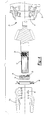
- FIG. 3 is a cross-sectional view, partially broken away, of a driveline assembly incorporating the subject invention.
- FIG. 4 is an exploded view of the driveline assembly of FIG. 3 .
- FIG. 5A is a side view of one type of quick connect.
- FIG. 5B is an end view of the quick connect of FIG. 5A in an installed position.
- FIG. 6A is a side view of an alternate quick connect.
- FIG. 6B is a cross-sectional end view of the quick connect of FIG. 6A in installed position.
- FIG. 6C is a cross-sectional end view of the quick connect of FIG. 6B in a disconnect position.
- FIG. 7 is a schematic view of a tandem drive axle incorporating the subject invention.
- FIG. 1 A A vehicle driveline assembly 10 with a single rear drive axle is shown in FIG. 1 A.
- An engine 12 and transmission 14 provide a driving output torque to an input driveshaft 16 .
- the driveshaft 16 is coupled to an input pinion shaft 18 for a drive axle 20 with a universal joint 22 .
- the drive axle 20 includes an axle housing 24 that defines a bowl 26 for a carrier 28 .
- the carrier 28 preferably includes a differential gear assembly 30 that splits rotational input torque from the longitudinally extending input shaft 18 into input torque for a pair of laterally extending axle shafts 32 .
- the axle shafts 32 are coupled to wheels 34 that drive the vehicle.
- FIG. 1 B An alternate embodiment of a driveline assembly 110 with a tandem drive axle is shown in FIG. 1 B.
- An engine 112 and transmission 114 provide driving torque to an input driveshaft 116 .
- the driveshaft 116 is coupled to an input shaft 118 for a tandem drive axle 120 with a first universal joint assembly 122 a.
- the tandem drive axle 120 includes a forward-rear axle 120 a and a rear-rear axle 120 b that are coupled together with an interaxle driveshaft 132 .
- the forward-rear axle 120 a includes an axle housing 124 a that defines a bowl 126 a for a carrier or differential 128 a .
- the carrier 128 a includes a differential gear assembly 130 a that splits torque from the input pinion shaft 118 into torque for the forward-rear and rear-rear drive axles.
- Each axle similarly drives axle shafts in a manner as shown in FIG. 1 A.
- the rear-rear axle 120 b includes an axle housing 124 b that defines a bowl 126 b for a carrier or differential 128 b .
- the carrier 128 b includes a differential gear assembly 130 b that splits torque from the interaxle driveshaft 132 into torque for driving axle shafts in a similar manner as shown in FIG. 1 A and as noted above.
- An output thru-shaft 134 from the forward-rear axle 120 a is coupled to the interaxle driveshaft 132 with a second universal joint assembly 122 b .
- a third universal joint assembly 122 c couples the opposite end of the interaxle driveshaft 132 to an input pinion shaft 136 of the rear-rear-axle 120 b.
- universal joints 22 , 122 include a pair of yoke members 22 a , 22 b , interconnected by a center cross 22 c , as shown in FIG. 2 .
- One yoke member 22 a is supported on one of the input shafts, i.e. the input pinion shaft 18 , 118 , 136 and/or the output thru-shaft 134 and the mating yoke member 22 b is supported on the driveshaft 16 , 116 , or interaxle driveshaft 132 .
- Bearing assemblies 40 are mounted within the axles 20 , 120 a , 120 b to rotatably support the input pinion shafts 18 , 118 , 136 and the output thru-shaft 134 .
- the operation of universal joints is well known in the art and will not be discussed in detail.
- the input pinion shaft 18 supports a pinion gear 42 that drivingly engages the gear assembly 30 .
- the bearing assembly 40 supports the input pinion shaft 18 for rotation relative to the axle housing 24 .
- a retaining ring 44 engages and retains the bearing assembly 40 on the shaft 18 .
- the yoke member 22 a is then separately installed on the shaft 18 .
- a seal 46 is installed between the retaining ring 44 and a portion of the axle housing 24 to prevent contaminants from interfering with the bearings 40 or gear assembly 30 .
- the input pinion shaft 18 preferably has a first mounting portion 50 for receiving the retaining ring 44 and a second mounting portion 52 for receiving the yoke member 22 .
- the first mounting portion 50 is a threaded exterior surface portion on the shaft 18 and the second mounting portion 52 is a splined exterior surface portion on the shaft 18 .
- the retaining ring 44 includes a threaded inner bore 56 that threadably engages the threaded exterior surface portion 50 on the shaft 18 .
- 2 3 ⁇ 8 fine threads are use for the threaded exterior surface 50 and the threaded inner bore 56 , however, other thread sizes could also be used.
- the yoke member 22 a includes a splined inner bore 58 that is received on the splined exterior surface portion 52 of the shaft 18 .
- the retaining ring 44 is tightened against the bearing assembly 40 to a predetermined torque level to supply a predetermined preload bearing force.
- the retaining ring 44 preferably includes a hex-head portion 60 to facilitate this operation.
- the predetermined torque level and bearing preload force vary depending upon the driveline size/capacity and the vehicle application.
- the yoke member 22 a can be removed without having to remove the retaining ring 44 from the shaft 18 . Additionally, the yoke member 22 a can be re-installed without affecting the retaining ring 44 . Thus, the proper bearing preload force is applied during initial assembly and is not affected during removal of the yoke member 22 a for repair, service, or change-out.
- the retaining ring 44 is positioned between the bearing assembly 40 and the yoke member 22 a.
- Each of the yoke members 22 a , 22 b includes a quick connect/disconnect device 62 that permits the yoke member 22 a , 22 b to be easily removed for repair, replacement, or change-out.
- the device 62 is easily movable between connect and disconnect conditions.
- the device 62 includes a longitudinally extending slot 64 formed in a body portion 66 of the yoke member 22 a adjacent to the splined inner bore 58 .
- the slot 64 is preferably open at one end 70 of the yoke member 22 a and defines a pair of slot edges 72 .
- a laterally extending thru-hole 74 is formed perpendicular to the slot 64 and the splines.
- the clamping member 76 is inserted into the thru-hole 74 to apply a clamping force on the opposing edges 72 of the slot 64 to clamp the yoke member 22 a to the shaft 18 .
- the clamping force is released.
- the clamping member 76 is a fastener having a head portion 78 engaging one side of the body portion 66 and a threaded end 80 extending outwardly from an opposite side of the body portion 66 .
- a nut 82 is tightened against the opposite side of the body portion 66 to draw the opposing slot edges 72 together to clamp the yoke member 22 a on the shaft 18 .
- the device 62 includes a laterally extending hole 84 formed in the body portion of the yoke member 22 a adjacent to the splined inner bore 58 .
- the splined inner bore 58 is discontinuous, i.e. there is a portion of the bore that does not include splines.
- This portion of the bore 58 is in the form of a small opening 86 that is in communication with the laterally extending hole 84 of the yoke member 22 a .
- a pin 88 is biased to engage an edge 90 of the small opening 86 (FIG.
- a slug 92 is installed at one end of the hole 84 to provide a fixed surface to support one end of a spring 94 .
- the opposite end of the spring 94 is engaged with an enlarged base portion 96 of the pin 88 .
- a bushing 98 is installed within the hole 84 at a narrowing neck portion 100 of the pin 88 .
- a shoulder 102 formed between the base 96 and neck 100 portions of the pin 88 , engages the edge 90 of the small opening 86 to connect the yoke member 22 a to the shaft 18 .
- quick connect/disconnect devices 62 shown in FIGS. 3-6 could be used for any yoke member 22 a , 22 b in the driveline 10 , 110 assembly. Further, the quick connect/disconnect devices 62 can be used for either a single axle 20 or a tandem axle 120 .
- FIG. 7 A tandem axle configuration is shown in FIG. 7 .
- the retaining ring 44 is preferably mounted on the output thru-shaft 134 in a similar manner as discussed above with regard to the single drive axle configuration, i.e., the retaining ring 44 is preferably threadably attached to the output thru-shaft 134 .
- the retaining ring 44 is positioned between bearing assembly 140 and the gearing assembly 130 a (see FIG. 1B) to retain the bearing assembly 140 at a proper location.
- the splined attachment between the yoke member 22 a and the thru-shaft 134 allows the yoke member 22 a to slide relative to the shaft 134 to permit installation of the interaxle driveshaft 132 .
- the interaxle driveshaft 132 is a single piece component of fixed length, i.e. is non-telescoping. This configuration facilitates assembly of the driveline 120 .
- One end of the interaxle driveshaft 132 is connected to the rear-rear axle 120 b and the opposite end of the interaxle driveshaft 132 is connected to the yoke member 22 a , which slides on the output thru-shaft 134 to provide variable length adjustment.
- sliding yoke member 22 a is shown as being used on the output of the forward-rear axle 120 a it should be understood that a similar sliding yoke member 22 a could be also used on the rear-rear axle 120 b .
- tandem configuration shown in FIG. 7 can be used with standard hypoid gearing (rear-rear pinion below axle centerline) or with amboid gearing (rear-rear pinion above axle centerline).
- the retaining ring 44 can be used simply to retain a bearing assembly 140 in place or can be used to provide a preload force as discussed above in relation to a single drive axle 20 .
- the separate retaining ring 44 and yoke members 22 a can be used on a tandem axle assembly 120 that utilizes a telescoping interaxle driveshaft (not shown) as disclosed in U.S. Pat. No. 5,951,402 assigned to the assignee of the present invention and herein incorporated by reference.
- the quick connect/disconnect assembly in this configuration would include the interaxle driveshaft with a splined formed tube (also known as the IZAK spline).
- This assembly would also include two (2) weld yokes and centerparts kits with clamp yokes attached at both ends.
- the subject invention simplifies assembly of driveline components in addition to improving performance. Further, service, repair, change-out, and other driveline maintenance operations are simplified with the use of quick connect/disconnect clamping yoke members.
Abstract
Description
Claims (17)
Priority Applications (1)
| Application Number | Priority Date | Filing Date | Title |
|---|---|---|---|
| US10/041,442 US6761237B2 (en) | 2002-01-08 | 2002-01-08 | Quick connect/disconnect driveline assembly |
Applications Claiming Priority (1)
| Application Number | Priority Date | Filing Date | Title |
|---|---|---|---|
| US10/041,442 US6761237B2 (en) | 2002-01-08 | 2002-01-08 | Quick connect/disconnect driveline assembly |
Publications (2)
| Publication Number | Publication Date |
|---|---|
| US20030130047A1 US20030130047A1 (en) | 2003-07-10 |
| US6761237B2 true US6761237B2 (en) | 2004-07-13 |
Family
ID=21916531
Family Applications (1)
| Application Number | Title | Priority Date | Filing Date |
|---|---|---|---|
| US10/041,442 Expired - Lifetime US6761237B2 (en) | 2002-01-08 | 2002-01-08 | Quick connect/disconnect driveline assembly |
Country Status (1)
| Country | Link |
|---|---|
| US (1) | US6761237B2 (en) |
Cited By (6)
| Publication number | Priority date | Publication date | Assignee | Title |
|---|---|---|---|---|
| US20090243373A1 (en) * | 2008-03-25 | 2009-10-01 | International Truck Intellectual Property Company, Llc | Drive away axle assembly |
| US20110011206A1 (en) * | 2009-07-14 | 2011-01-20 | Knight Donn C | Driveline yoke with brake rotor |
| US20120238393A1 (en) * | 2011-03-14 | 2012-09-20 | Martin Iii Robert J | Carrier assembly with threaded adjustment member |
| US20140105680A1 (en) * | 2012-10-15 | 2014-04-17 | Dana Automotive Systems Group, Llc | Drive pinion fastening assembly |
| US9309928B2 (en) | 2010-08-04 | 2016-04-12 | Arvinmeritor Technology, Llc | Yoke with stiffness ring |
| US10316950B2 (en) * | 2017-03-10 | 2019-06-11 | Arvinmeritor Technology, Llc | Axle assembly having a drive pinion and a bearing preload element |
Families Citing this family (3)
| Publication number | Priority date | Publication date | Assignee | Title |
|---|---|---|---|---|
| US8795125B2 (en) | 2012-03-18 | 2014-08-05 | Dana Heavy Vehicle Systems Group, Llc | Tandem axle with optimized inter-axle drive |
| EP3423726A1 (en) * | 2016-03-01 | 2019-01-09 | Vestas Wind Systems A/S | A wind turbine comprising a torque transmitting coupling |
| JP2017207126A (en) * | 2016-05-18 | 2017-11-24 | 株式会社ジェイテクト | Universal joint yoke and intermediate shaft |
Citations (25)
| Publication number | Priority date | Publication date | Assignee | Title |
|---|---|---|---|---|
| US399572A (en) | 1889-03-12 | Motor for railway-cars | ||
| US639178A (en) | 1899-04-07 | 1899-12-12 | Herman L Maddox | Vehicle-axle. |
| US1389042A (en) | 1919-06-07 | 1921-08-30 | Charles E Thompson | Driving mechanism |
| US2107721A (en) | 1936-04-09 | 1938-02-08 | Borg Warner | Universal drive mechanism |
| US2116290A (en) | 1936-09-10 | 1938-05-03 | Spicer Mfg Corp | Sealed propeller shaft |
| US2680634A (en) | 1952-07-09 | 1954-06-08 | Rolls Royce | Shaft coupling |
| US2706125A (en) | 1951-09-14 | 1955-04-12 | Rolls Royce | Shaft couplings |
| US3029888A (en) * | 1959-04-16 | 1962-04-17 | County Commercial Cars Ltd | Driving transmission for vehicles having multiple driven wheel axles |
| US3041857A (en) | 1960-03-25 | 1962-07-03 | Borg Warner | Flexible couplings |
| US3318173A (en) * | 1965-03-19 | 1967-05-09 | American Motors Corp | Differential gear assembly |
| US3323844A (en) * | 1965-02-24 | 1967-06-06 | American Motors Corp | Differential gear assembly and locking mechanism |
| US3367142A (en) | 1966-05-31 | 1968-02-06 | Dana Corp | Slip spline assembly |
| US3367138A (en) * | 1966-07-21 | 1968-02-06 | Curtiss Wright Corp | Detachable shaft coupling |
| US3400558A (en) | 1965-04-09 | 1968-09-10 | Dana Corp | Low friction sliding and torque transmitting connection |
| USRE27068E (en) | 1970-01-26 | 1971-02-23 | Slip spline assembly | |
| US3706350A (en) * | 1970-12-09 | 1972-12-19 | Boise Cascade Corp | Fully automatic locking interaxle differential for tandem vehicles |
| US3760920A (en) | 1972-08-14 | 1973-09-25 | Boeing Co | Power shaft coupling and uncoupling mechanism |
| US3905089A (en) * | 1974-02-22 | 1975-09-16 | Dana Corp | Method of constructing a one-piece aluminum differential housing |
| US4203306A (en) | 1977-10-21 | 1980-05-20 | Gelenkwellenbau Gmbh | Telescoping power take-off shaft with lockable length adjustment |
| US4365909A (en) * | 1978-11-15 | 1982-12-28 | Nadella | Coupling clamp and a method of manufacture therefor |
| US4475737A (en) | 1982-05-14 | 1984-10-09 | Dana Corporation | Slip spline sealing plug |
| US4754847A (en) * | 1986-12-31 | 1988-07-05 | Dana Corporation | Interaxle differential for tandem axle assembly |
| US5609540A (en) * | 1995-08-17 | 1997-03-11 | New Venture Gear, Inc. | Full-time double offset transfer case |
| US6189413B1 (en) * | 1999-07-12 | 2001-02-20 | American Axle & Manufacturing, Inc. | Captive molding with dissimilar material insert |
| US20030050126A1 (en) * | 2001-09-07 | 2003-03-13 | Arnold Bradley A. | Driveline assembly with reduced standout |
-
2002
- 2002-01-08 US US10/041,442 patent/US6761237B2/en not_active Expired - Lifetime
Patent Citations (25)
| Publication number | Priority date | Publication date | Assignee | Title |
|---|---|---|---|---|
| US399572A (en) | 1889-03-12 | Motor for railway-cars | ||
| US639178A (en) | 1899-04-07 | 1899-12-12 | Herman L Maddox | Vehicle-axle. |
| US1389042A (en) | 1919-06-07 | 1921-08-30 | Charles E Thompson | Driving mechanism |
| US2107721A (en) | 1936-04-09 | 1938-02-08 | Borg Warner | Universal drive mechanism |
| US2116290A (en) | 1936-09-10 | 1938-05-03 | Spicer Mfg Corp | Sealed propeller shaft |
| US2706125A (en) | 1951-09-14 | 1955-04-12 | Rolls Royce | Shaft couplings |
| US2680634A (en) | 1952-07-09 | 1954-06-08 | Rolls Royce | Shaft coupling |
| US3029888A (en) * | 1959-04-16 | 1962-04-17 | County Commercial Cars Ltd | Driving transmission for vehicles having multiple driven wheel axles |
| US3041857A (en) | 1960-03-25 | 1962-07-03 | Borg Warner | Flexible couplings |
| US3323844A (en) * | 1965-02-24 | 1967-06-06 | American Motors Corp | Differential gear assembly and locking mechanism |
| US3318173A (en) * | 1965-03-19 | 1967-05-09 | American Motors Corp | Differential gear assembly |
| US3400558A (en) | 1965-04-09 | 1968-09-10 | Dana Corp | Low friction sliding and torque transmitting connection |
| US3367142A (en) | 1966-05-31 | 1968-02-06 | Dana Corp | Slip spline assembly |
| US3367138A (en) * | 1966-07-21 | 1968-02-06 | Curtiss Wright Corp | Detachable shaft coupling |
| USRE27068E (en) | 1970-01-26 | 1971-02-23 | Slip spline assembly | |
| US3706350A (en) * | 1970-12-09 | 1972-12-19 | Boise Cascade Corp | Fully automatic locking interaxle differential for tandem vehicles |
| US3760920A (en) | 1972-08-14 | 1973-09-25 | Boeing Co | Power shaft coupling and uncoupling mechanism |
| US3905089A (en) * | 1974-02-22 | 1975-09-16 | Dana Corp | Method of constructing a one-piece aluminum differential housing |
| US4203306A (en) | 1977-10-21 | 1980-05-20 | Gelenkwellenbau Gmbh | Telescoping power take-off shaft with lockable length adjustment |
| US4365909A (en) * | 1978-11-15 | 1982-12-28 | Nadella | Coupling clamp and a method of manufacture therefor |
| US4475737A (en) | 1982-05-14 | 1984-10-09 | Dana Corporation | Slip spline sealing plug |
| US4754847A (en) * | 1986-12-31 | 1988-07-05 | Dana Corporation | Interaxle differential for tandem axle assembly |
| US5609540A (en) * | 1995-08-17 | 1997-03-11 | New Venture Gear, Inc. | Full-time double offset transfer case |
| US6189413B1 (en) * | 1999-07-12 | 2001-02-20 | American Axle & Manufacturing, Inc. | Captive molding with dissimilar material insert |
| US20030050126A1 (en) * | 2001-09-07 | 2003-03-13 | Arnold Bradley A. | Driveline assembly with reduced standout |
Cited By (10)
| Publication number | Priority date | Publication date | Assignee | Title |
|---|---|---|---|---|
| US20090243373A1 (en) * | 2008-03-25 | 2009-10-01 | International Truck Intellectual Property Company, Llc | Drive away axle assembly |
| US7641289B2 (en) | 2008-03-25 | 2010-01-05 | International Truck Intellectual Property Company, Llc | Drive away axle assembly |
| US20110011206A1 (en) * | 2009-07-14 | 2011-01-20 | Knight Donn C | Driveline yoke with brake rotor |
| US9309928B2 (en) | 2010-08-04 | 2016-04-12 | Arvinmeritor Technology, Llc | Yoke with stiffness ring |
| US20120238393A1 (en) * | 2011-03-14 | 2012-09-20 | Martin Iii Robert J | Carrier assembly with threaded adjustment member |
| US9074677B2 (en) * | 2011-03-14 | 2015-07-07 | Arvinmeritor Technology, Llc | Carrier assembly with threaded adjustment member |
| US20140105680A1 (en) * | 2012-10-15 | 2014-04-17 | Dana Automotive Systems Group, Llc | Drive pinion fastening assembly |
| US9618050B2 (en) * | 2012-10-15 | 2017-04-11 | Dana Automotive Systems Group, Llc | Drive pinion fastening assembly |
| US10316950B2 (en) * | 2017-03-10 | 2019-06-11 | Arvinmeritor Technology, Llc | Axle assembly having a drive pinion and a bearing preload element |
| US10451164B2 (en) | 2017-03-10 | 2019-10-22 | Arvinmeritor Technology, Llc | Axle assembly having a drive pinion and a bearing preload element |
Also Published As
| Publication number | Publication date |
|---|---|
| US20030130047A1 (en) | 2003-07-10 |
Similar Documents
| Publication | Publication Date | Title |
|---|---|---|
| US6761237B2 (en) | Quick connect/disconnect driveline assembly | |
| US7345469B2 (en) | Axle assembly with sensor mount | |
| US6478709B1 (en) | Axle end play adjustment systems and methods | |
| US6582151B2 (en) | Driving axle assembly | |
| CA2084379C (en) | Driveline torque fuse | |
| US20100119301A1 (en) | Device for the rotationally fixed connection of a pin gearbox to an articulated body of a drive coupling of a drive shaft | |
| US20140205365A1 (en) | Premium performance ball joint and system | |
| US4331210A (en) | Live spindle vehicle drive wheel assembly with axially moveable axle | |
| US2174223A (en) | Universal joint | |
| US7029398B1 (en) | Flange yoke and companion flange supported on a splined shaft | |
| US6371268B1 (en) | Retention mechanism for vehicle wheel assembly | |
| GB2055175A (en) | Drive shafts | |
| US4936003A (en) | Improved splined joint remover | |
| US7004277B2 (en) | Power blocks | |
| US20030064817A1 (en) | Wheel hub/joint unit with clamping and separating device | |
| US4815337A (en) | Locking ring for independent rear suspensions | |
| US8523689B2 (en) | Axially adjustable driveshaft assembly | |
| US6957710B2 (en) | Tandem drive axle assembly | |
| KR101013726B1 (en) | Coupling shaft for vehicle's propeller shaft | |
| US5868626A (en) | Universal joint yoke having axially-extending grooves | |
| US6016597A (en) | Apparatus and method for retaining bearing cups on a universal joint during lubrication | |
| US6557659B1 (en) | Driveline assembly with vibration dampener | |
| AU650743B2 (en) | Flexible coupling | |
| DE19732685A1 (en) | Grease nipple | |
| US6279422B1 (en) | Endplay adjustment mechanism for colinear shafts |
Legal Events
| Date | Code | Title | Description |
|---|---|---|---|
| AS | Assignment |
Owner name: MERITOR HEAVY VEHICLE TECHNOLOGY, LLC, MICHIGAN Free format text: ASSIGNMENT OF ASSIGNORS INTEREST;ASSIGNORS:BRISSETTE, RONALD N.;LENTINI, ANTHONY;STEELE, CHRIS;AND OTHERS;REEL/FRAME:012477/0229;SIGNING DATES FROM 20011203 TO 20020102 |
|
| STCF | Information on status: patent grant |
Free format text: PATENTED CASE |
|
| CC | Certificate of correction | ||
| AS | Assignment |
Owner name: ARVINMERITOR TECHNOLOGY, LLC, MICHIGAN Free format text: CHANGE OF NAME;ASSIGNOR:MERITOR HEAVY VEHICLE TECHNOLOGY, LLC;REEL/FRAME:018362/0743 Effective date: 20011221 |
|
| AS | Assignment |
Owner name: JPMORGAN CHASE BANK, NATIONAL ASSOCIATION, FOR ITS Free format text: SECURITY AGREEMENT;ASSIGNOR:ARVINMERITOR TECHNOLOGY, LLC;REEL/FRAME:018524/0669 Effective date: 20060823 |
|
| REMI | Maintenance fee reminder mailed | ||
| FPAY | Fee payment |
Year of fee payment: 4 |
|
| SULP | Surcharge for late payment | ||
| FPAY | Fee payment |
Year of fee payment: 8 |
|
| FPAY | Fee payment |
Year of fee payment: 12 |
|
| AS | Assignment |
Owner name: AXLETECH INTERNATIONAL IP HOLDINGS, LLC, MICHIGAN Free format text: RELEASE BY SECURED PARTY;ASSIGNOR:JPMORGAN CHASE BANK, N.A., AS ADMINISTRATIVE AGENT;REEL/FRAME:061521/0550 Effective date: 20220803 Owner name: MERITOR TECHNOLOGY, LLC, MICHIGAN Free format text: RELEASE BY SECURED PARTY;ASSIGNOR:JPMORGAN CHASE BANK, N.A., AS ADMINISTRATIVE AGENT;REEL/FRAME:061521/0550 Effective date: 20220803 Owner name: MOTOR HEAVY VEHICLE SYSTEMS, LLC, MICHIGAN Free format text: RELEASE BY SECURED PARTY;ASSIGNOR:JPMORGAN CHASE BANK, N.A., AS ADMINISTRATIVE AGENT;REEL/FRAME:061521/0550 Effective date: 20220803 Owner name: ARVINMERITOR OE, LLC, MICHIGAN Free format text: RELEASE BY SECURED PARTY;ASSIGNOR:JPMORGAN CHASE BANK, N.A., AS ADMINISTRATIVE AGENT;REEL/FRAME:061521/0550 Effective date: 20220803 Owner name: MERITOR HEAVY VEHICLE SYSTEMS, LLC, MICHIGAN Free format text: RELEASE BY SECURED PARTY;ASSIGNOR:JPMORGAN CHASE BANK, N.A., AS ADMINISTRATIVE AGENT;REEL/FRAME:061521/0550 Effective date: 20220803 Owner name: ARVINMERITOR TECHNOLOGY, LLC, MICHIGAN Free format text: RELEASE BY SECURED PARTY;ASSIGNOR:JPMORGAN CHASE BANK, N.A., AS ADMINISTRATIVE AGENT;REEL/FRAME:061521/0550 Effective date: 20220803 Owner name: MAREMOUNT CORPORATION, MICHIGAN Free format text: RELEASE BY SECURED PARTY;ASSIGNOR:JPMORGAN CHASE BANK, N.A., AS ADMINISTRATIVE AGENT;REEL/FRAME:061521/0550 Effective date: 20220803 Owner name: EUCLID INDUSTRIES, LLC, MICHIGAN Free format text: RELEASE BY SECURED PARTY;ASSIGNOR:JPMORGAN CHASE BANK, N.A., AS ADMINISTRATIVE AGENT;REEL/FRAME:061521/0550 Effective date: 20220803 Owner name: GABRIEL RIDE CONTROL PRODUCTS, INC., MICHIGAN Free format text: RELEASE BY SECURED PARTY;ASSIGNOR:JPMORGAN CHASE BANK, N.A., AS ADMINISTRATIVE AGENT;REEL/FRAME:061521/0550 Effective date: 20220803 Owner name: ARVIN TECHNOLOGIES, INC., MICHIGAN Free format text: RELEASE BY SECURED PARTY;ASSIGNOR:JPMORGAN CHASE BANK, N.A., AS ADMINISTRATIVE AGENT;REEL/FRAME:061521/0550 Effective date: 20220803 Owner name: MERITOR TRANSMISSION CORPORATION, MICHIGAN Free format text: RELEASE BY SECURED PARTY;ASSIGNOR:JPMORGAN CHASE BANK, N.A., AS ADMINISTRATIVE AGENT;REEL/FRAME:061521/0550 Effective date: 20220803 Owner name: ARVINMERITOR, INC., MICHIGAN Free format text: RELEASE BY SECURED PARTY;ASSIGNOR:JPMORGAN CHASE BANK, N.A., AS ADMINISTRATIVE AGENT;REEL/FRAME:061521/0550 Effective date: 20220803 |