US6506010B1 - Method and apparatus for compressor control and operation in industrial gas turbines using stall precursors - Google Patents
Method and apparatus for compressor control and operation in industrial gas turbines using stall precursors Download PDFInfo
- Publication number
- US6506010B1 US6506010B1 US09/835,825 US83582501A US6506010B1 US 6506010 B1 US6506010 B1 US 6506010B1 US 83582501 A US83582501 A US 83582501A US 6506010 B1 US6506010 B1 US 6506010B1
- Authority
- US
- United States
- Prior art keywords
- compressor
- stall
- stage
- pressure
- value
- Prior art date
- Legal status (The legal status is an assumption and is not a legal conclusion. Google has not performed a legal analysis and makes no representation as to the accuracy of the status listed.)
- Expired - Lifetime
Links
Images


Classifications
-
- F—MECHANICAL ENGINEERING; LIGHTING; HEATING; WEAPONS; BLASTING
- F04—POSITIVE - DISPLACEMENT MACHINES FOR LIQUIDS; PUMPS FOR LIQUIDS OR ELASTIC FLUIDS
- F04D—NON-POSITIVE-DISPLACEMENT PUMPS
- F04D27/00—Control, e.g. regulation, of pumps, pumping installations or pumping systems specially adapted for elastic fluids
- F04D27/02—Surge control
-
- F—MECHANICAL ENGINEERING; LIGHTING; HEATING; WEAPONS; BLASTING
- F05—INDEXING SCHEMES RELATING TO ENGINES OR PUMPS IN VARIOUS SUBCLASSES OF CLASSES F01-F04
- F05D—INDEXING SCHEME FOR ASPECTS RELATING TO NON-POSITIVE-DISPLACEMENT MACHINES OR ENGINES, GAS-TURBINES OR JET-PROPULSION PLANTS
- F05D2270/00—Control
- F05D2270/01—Purpose of the control system
- F05D2270/02—Purpose of the control system to control rotational speed (n)
- F05D2270/021—Purpose of the control system to control rotational speed (n) to prevent overspeed
-
- F—MECHANICAL ENGINEERING; LIGHTING; HEATING; WEAPONS; BLASTING
- F05—INDEXING SCHEMES RELATING TO ENGINES OR PUMPS IN VARIOUS SUBCLASSES OF CLASSES F01-F04
- F05D—INDEXING SCHEME FOR ASPECTS RELATING TO NON-POSITIVE-DISPLACEMENT MACHINES OR ENGINES, GAS-TURBINES OR JET-PROPULSION PLANTS
- F05D2270/00—Control
- F05D2270/01—Purpose of the control system
- F05D2270/04—Purpose of the control system to control acceleration (u)
- F05D2270/042—Purpose of the control system to control acceleration (u) by keeping it below damagingly high values
-
- F—MECHANICAL ENGINEERING; LIGHTING; HEATING; WEAPONS; BLASTING
- F05—INDEXING SCHEMES RELATING TO ENGINES OR PUMPS IN VARIOUS SUBCLASSES OF CLASSES F01-F04
- F05D—INDEXING SCHEME FOR ASPECTS RELATING TO NON-POSITIVE-DISPLACEMENT MACHINES OR ENGINES, GAS-TURBINES OR JET-PROPULSION PLANTS
- F05D2270/00—Control
- F05D2270/01—Purpose of the control system
- F05D2270/09—Purpose of the control system to cope with emergencies
-
- F—MECHANICAL ENGINEERING; LIGHTING; HEATING; WEAPONS; BLASTING
- F05—INDEXING SCHEMES RELATING TO ENGINES OR PUMPS IN VARIOUS SUBCLASSES OF CLASSES F01-F04
- F05D—INDEXING SCHEME FOR ASPECTS RELATING TO NON-POSITIVE-DISPLACEMENT MACHINES OR ENGINES, GAS-TURBINES OR JET-PROPULSION PLANTS
- F05D2270/00—Control
- F05D2270/01—Purpose of the control system
- F05D2270/10—Purpose of the control system to cope with, or avoid, compressor flow instabilities
- F05D2270/101—Compressor surge or stall
-
- F—MECHANICAL ENGINEERING; LIGHTING; HEATING; WEAPONS; BLASTING
- F05—INDEXING SCHEMES RELATING TO ENGINES OR PUMPS IN VARIOUS SUBCLASSES OF CLASSES F01-F04
- F05D—INDEXING SCHEME FOR ASPECTS RELATING TO NON-POSITIVE-DISPLACEMENT MACHINES OR ENGINES, GAS-TURBINES OR JET-PROPULSION PLANTS
- F05D2270/00—Control
- F05D2270/30—Control parameters, e.g. input parameters
- F05D2270/301—Pressure
-
- F—MECHANICAL ENGINEERING; LIGHTING; HEATING; WEAPONS; BLASTING
- F05—INDEXING SCHEMES RELATING TO ENGINES OR PUMPS IN VARIOUS SUBCLASSES OF CLASSES F01-F04
- F05D—INDEXING SCHEME FOR ASPECTS RELATING TO NON-POSITIVE-DISPLACEMENT MACHINES OR ENGINES, GAS-TURBINES OR JET-PROPULSION PLANTS
- F05D2270/00—Control
- F05D2270/30—Control parameters, e.g. input parameters
- F05D2270/303—Temperature
- F05D2270/3032—Temperature excessive temperatures, e.g. caused by overheating
-
- F—MECHANICAL ENGINEERING; LIGHTING; HEATING; WEAPONS; BLASTING
- F05—INDEXING SCHEMES RELATING TO ENGINES OR PUMPS IN VARIOUS SUBCLASSES OF CLASSES F01-F04
- F05D—INDEXING SCHEME FOR ASPECTS RELATING TO NON-POSITIVE-DISPLACEMENT MACHINES OR ENGINES, GAS-TURBINES OR JET-PROPULSION PLANTS
- F05D2270/00—Control
- F05D2270/40—Type of control system
- F05D2270/44—Type of control system active, predictive, or anticipative
Definitions
- This invention relates to non-intrusive techniques for monitoring the health of rotating mechanical components. More particularly, the invention relates to a method and apparatus for monitoring and controlling the performance of an axial flow compressor or a gas turbine by detecting precursors to rotating stall and surge.
- compressor stall In gas turbines used for power generation, a compressor must be allowed to operate at a higher pressure ratio to achieve a higher machine efficiency.
- compressor stall a phenomenon known as compressor stall, wherein the pressure ratio of the compressor initially exceeds some critical value at a given speed, resulting in a subsequent reduction of compressor pressure ratio and airflow delivered to the combustor.
- Compressor stall may result from a variety of reasons, such as when the engine is accelerated too rapidly, or when the inlet profile of air pressure or temperature becomes unduly distorted during normal operation of the engine. Compressor damage due to the ingestion of foreign objects or a malfunction of a portion of the engine control system may also result in a compressor stall and subsequent compressor degradation. If compressor stall remains undetected and permitted to continue, the combustor temperatures and the vibratory stresses induced in the compressor may become sufficiently high to cause damage to the gas turbine.
- the Gas Turbine Combined-Cycle power plant consisting of a Gas-Turbine based topping cycle and a Rankine-based bottoming cycle, continues to be the customer's preferred choice in power generation. This may be due to the relatively-low plant investment cost, and to the continuously-improving operating efficiency of the Gas Turbine based combined cycle, which combine to minimize the cost of electricity production.
- an optimal cycle pressure ratio is identified which maximizes combined-cycle efficiency. This optimal cycle pressure ratio is theoretically shown to increase with increasing firing temperature.
- Axial flow compressors which are at the heart of industrial Gas Turbines, are thus subjected to demands for ever-increasing levels of pressure ratio, with the simultaneous goals of minimal parts count, operational simplicity, and low overall cost.
- an axial flow compressor is expected to operate at a heightened level of cycle pressure ratio at a compression efficiency that augments the overall cycle efficiency.
- An axial flow compressor is also expected to perform in an aerodynamically and aero-mechanically stable manner over a wide range in mass flow rate associated with the varying power output characteristics of the combined cycle operation.
- the present invention solves the simultaneous need for high cycle pressure-ratio commensurate with high efficiency and ample surge margin throughout the operating range of a compressor.
- the present invention is particularly directed to a system and method for continuously monitoring and controlling the state of an axial flow compressor using stall precursors by varying the operating line parameters to account for compressor degradation thereby maintaining a predetermined level of compressor operability.
- a plurality of sensors are disposed about the compressor casing in a circumferential manner for measuring the dynamic pressure and dynamic velocity of gases flowing through the compressor. Measured data from the sensors is filtered and received by a real-time operating system for processing and storage. When the amount of stored data reaches a predetermined level, it is processed using a stall precursor detection algorithms to extract the magnitudes of the precursors.
- the precursor magnitudes are then compared with known baseline compressor values, and the difference is used to estimate a degraded compressor operating map.
- a corresponding compressor operability measure i.e., operating stall margin, is computed and compared to a design target. If the operability of the compressor is deemed insufficient, corrective actions are initiated by a real-time control system which causes to vary the operating limit line parameters thereby reducing loading on the compressor in order to maintain the required compressor operability level.
- Some of the corrective actions may include varying the operating line control parameters such as making adjustments to compressor variable vanes, temperature of inlet air, compressor air bleed, combustor fuel mix, etc. to operate the compressor at a near threshold level.
- the corrective actions are initiated prior to the occurrence of a compressor surge event and within a margin identified between a operating line threshold value and the occurrence of a compressor surge event. These corrective steps are iterated until the desired level of compressor operability is achieved.
- the exemplary embodiment of the present invention as illustrated herein provides a design and operational strategy that provides optimal pressure ratio and surge margin not only for cases where the inlet guide vanes (IGV's) are tracking along the nominal full flow schedule, but also for cases where the IGV's are closed down for reduced flow under power-turndown conditions.
- IGV's inlet guide vanes
- the present invention provides a method for monitoring and controlling a compressor, comprising the steps of: monitoring the pressure of gases flowing through the compressor; comparing the monitored pressure with predetermined baseline values to estimate compressor degradation; performing corrective actions to mitigate compressor degradation to maintain a pre-selected level of compressor operability; and iterating said corrective actions performing step until the monitored pressure lies within a predetermined threshold.
- the method further comprises performing signal processing on the monitored pressure to obtain a filtered pressure signal; and storing the filtered signal in a memory.
- the corrective actions are initiated by varying operating line parameters.
- the corrective actions include reducing the loading on the compressor.
- the operating line parameters are set to a near threshold value.
- the present invention provides an apparatus for monitoring the health of a compressor at least one sensor operatively coupled to measure the dynamic pressure of gases flowing through the compressor; a processing system coupled to at least one sensor, the system recording and processing the measurements made by at least one sensor.
- the apparatus further includes a comparator that compares the measurements with predetermined baseline values; and a real-time controller coupled to the comparator, the controller initiating corrective actions to prevent a compressor surge if the sensor measurements deviate from said predetermined baseline values.
- the apparatus further includes a system selector whereby the measured signals are selectively applied to provide a visual warning of compressor degradation.
- the present invention provides a method for continuously monitoring and controlling surge events in a compressor included in a gas turbine according to various embodiments of the present invention.
- the present invention provides an apparatus for continuously monitoring and controlling an axial flow compressor system having means for measuring the dynamic pressure of gases flowing through the compressor; means for processing the dynamic pressure measurements by at least one precursor detection algorithm to calculate precursor signal magnitudes; means for comparing the precursor signal magnitudes with predetermined baseline values; and means for performing corrective actions if the precursor signal magnitudes deviate from the baseline values.
- the present invention provides a method for continuously monitoring and controlling an axial flow compressor by providing a means for measuring the dynamic pressure of gases flowing through the compressor; providing a means for processing the dynamic pressure measurements by at least one precursor detection algorithm to calculate precursor signal magnitudes; providing a means for comparing the precursor signal magnitudes with predetermined baseline values; and providing a means for performing corrective actions if the precursor signal magnitudes deviate from said baseline values.
- the present invention provides a stall precursor detector system for a gas turbine of the type having an axial flow compressor, the detector system having at least one sensor coupled to measure the dynamic pressure of gases flowing through the compressor; a processor system coupled to at least one sensor, the processor system including a precursor detection algorithm for processing the dynamic pressure data with predetermined baseline values; a comparator coupled to the processor system for comparing the sensor measurements with predetermined baseline values; and a real-time controller coupled to the comparator for performing corrective actions to prevent a subsequent compressor surge if the measured pressure deviates from the predetermined baseline values.
- FIG. 1 is a schematic representation of a typical gas turbine engine
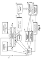
- FIG. 2 illustrates a schematic representation of a compressor control operation using stall precursors
- FIG. 3 illustrates a different embodiment of the present invention where a stall onset signal is applied to provide a visual indication
- FIG. 4 illustrates the use of stall precursor data as in FIG. 1 to provide improved performance.
- a gas turbine engine is shown at 10 as comprising a housing 12 having a compressor 14 , which may be of the axial flow type, within housing 12 .
- the compressor 14 receives air through an annular air inlet 16 and delivers compressed air to a combustion chamber 18 .
- air is burned with fuel and the resulting combustion gases are directed by a nozzle or guide vane structure 20 to the rotor blades of a turbine rotor 24 for driving the rotor.
- a shaft 13 drivably connects the turbine rotor 24 with the compressor 14 . From the turbine blades, the exhaust gases discharge rearwardly through an exhaust duct 19 into the surrounding atmosphere.
- FIG. 2 there is shown in block diagram fashion the apparatus and method for continuously monitoring and controlling an axial flow compressor 14 by measuring the dynamic pressure and dynamic velocity of gases flowing through the compressor.
- a single stage of the compressor is illustrated in the present embodiment to better explain the inventive concept. In fact, several such stages may be present in a compressor.
- sensors 30 are disposed about the casing of a compressor 14 for measuring the dynamic pressure/velocity of gases flowing through the compressor 14 .
- the dynamic pressure/velocity data is fed to system 32 for processing and storage. Appropriate signal processing, such as filtering the signals is performed to clean the signals received by sensors 30 .
- a stall precursor detection algorithm embodied in system 34 processes the received data from sensors 30 to extract magnitudes of the stall precursors as indicated at 36 .
- Received data from sensors 30 may be processed using a plurality of stall detection algorithms operating in parallel, thus increasing the confidence of stall precursor detection.
- a number of stall precursor magnitudes obtained from respective sensors may be combined in a system 38 , and the combined magnitude is compared with a combined baseline stall magnitude by system 42 to define an upper limit of compressor degradation.
- the real time control system 32 obtains pressure and velocity ratios from compressor 14 and calculates an operating condition of compressor 14 as indicated at 40 .
- the baseline stall measures may be extrapolated from the knowledge of the operating condition of compressor 14 .
- control system 32 may also inform an operator via maintenance flags or a visual warning, and the like regarding compressor operability.
- Active controls by control system 32 may be used to set operating line parameters for the operation of axial flow compressor 14 . Once the operating line parameters are set, pressure and velocity of gases flowing through the compressor are measured—the measured values representing stall precursors. The measured values are filtered to remove noise and subsequently processed to extract the magnitudes. The extracted magnitudes are compared with predetermined baseline compressor values. If the extracted magnitudes deviate from the predetermined baseline values, then a signal indicative of compressor degradation is issued. Subsequently, corrective actions are initiated by varying the operating limit line parameters to cause the compressor to function with a desired level of operability. Corrective actions are iterated until the desired level of operability is achieved.
- Comparison of measured pressure/velocity of gases flowing through compressor 14 to that of baseline compressor values is indicative of the operability of the compressor.
- This compressor operability data may be used to initiate the desired control system corrective actions to prevent a compressor surge, thus allowing the compressor to operate with a higher efficiency than if additional margin were required to avoid near stall operation.
- Stall precursor signals indicative of onset of compressor stall may also be provided, as illustrated in FIG. 4, to a display 64 or other indicator means so that an operator may manually initiate corrective measures to prevent a compressor surge and avoid near stall operation.
- FIG. 3 there is shown in block diagram fashion, the use of stall precursor data as obtained in FIG. 2 to provide improved performance of compressor 14 .
- stall precursor data is obtained from several gas turbines, in a manner similar to the operation as illustrated in FIG. 2, a bench-marking operation is performed as indicated at 50 on the received data to extract data to identify the feasibility of performance upgrades and safety improvement offerings as indicated at 54 , thereby leading to enhancement in profitability.
- the extracted data as indicated at 52 may also be used for next generation designs which may likely lead to new products.
Abstract
An apparatus for monitoring the health of a compressor including at least one sensor operatively coupled to measure the dynamic pressure of gases flowing through the compressor, a processing system coupled to at least one sensor, the processor system recording and processing the measurements made by at least one sensor. The apparatus further includes a comparator that compares the sensor measurements with predetermined baseline values, and a real-time controller coupled to the comparator, the controller initiating corrective actions to prevent a compressor surge if the sensor measurements deviate from the predetermined baseline values.
Description
This invention relates to non-intrusive techniques for monitoring the health of rotating mechanical components. More particularly, the invention relates to a method and apparatus for monitoring and controlling the performance of an axial flow compressor or a gas turbine by detecting precursors to rotating stall and surge.
In gas turbines used for power generation, a compressor must be allowed to operate at a higher pressure ratio to achieve a higher machine efficiency. During operation of a gas turbine, there may occur a phenomenon known as compressor stall, wherein the pressure ratio of the compressor initially exceeds some critical value at a given speed, resulting in a subsequent reduction of compressor pressure ratio and airflow delivered to the combustor. Compressor stall may result from a variety of reasons, such as when the engine is accelerated too rapidly, or when the inlet profile of air pressure or temperature becomes unduly distorted during normal operation of the engine. Compressor damage due to the ingestion of foreign objects or a malfunction of a portion of the engine control system may also result in a compressor stall and subsequent compressor degradation. If compressor stall remains undetected and permitted to continue, the combustor temperatures and the vibratory stresses induced in the compressor may become sufficiently high to cause damage to the gas turbine.
The global market for efficient power generation equipment has been expanding at a rapid rate since the mid-1980's—this trend is projected to continue in the future. The Gas Turbine Combined-Cycle power plant, consisting of a Gas-Turbine based topping cycle and a Rankine-based bottoming cycle, continues to be the customer's preferred choice in power generation. This may be due to the relatively-low plant investment cost, and to the continuously-improving operating efficiency of the Gas Turbine based combined cycle, which combine to minimize the cost of electricity production.
It is well known that elevated firing temperatures enable increases in combined cycle efficiency and specific power. It is further known that, for a given firing temperature, an optimal cycle pressure ratio is identified which maximizes combined-cycle efficiency. This optimal cycle pressure ratio is theoretically shown to increase with increasing firing temperature. Axial flow compressors, which are at the heart of industrial Gas Turbines, are thus subjected to demands for ever-increasing levels of pressure ratio, with the simultaneous goals of minimal parts count, operational simplicity, and low overall cost. Further, an axial flow compressor is expected to operate at a heightened level of cycle pressure ratio at a compression efficiency that augments the overall cycle efficiency. An axial flow compressor is also expected to perform in an aerodynamically and aero-mechanically stable manner over a wide range in mass flow rate associated with the varying power output characteristics of the combined cycle operation.
Therefore, it would be desirable to have a reliable method and apparatus to determine the state/health of a compressor by determining the onset of a compressor surge prior to the event occurrence.
Accordingly, the present invention solves the simultaneous need for high cycle pressure-ratio commensurate with high efficiency and ample surge margin throughout the operating range of a compressor. The present invention is particularly directed to a system and method for continuously monitoring and controlling the state of an axial flow compressor using stall precursors by varying the operating line parameters to account for compressor degradation thereby maintaining a predetermined level of compressor operability. A plurality of sensors are disposed about the compressor casing in a circumferential manner for measuring the dynamic pressure and dynamic velocity of gases flowing through the compressor. Measured data from the sensors is filtered and received by a real-time operating system for processing and storage. When the amount of stored data reaches a predetermined level, it is processed using a stall precursor detection algorithms to extract the magnitudes of the precursors. The precursor magnitudes are then compared with known baseline compressor values, and the difference is used to estimate a degraded compressor operating map. A corresponding compressor operability measure, i.e., operating stall margin, is computed and compared to a design target. If the operability of the compressor is deemed insufficient, corrective actions are initiated by a real-time control system which causes to vary the operating limit line parameters thereby reducing loading on the compressor in order to maintain the required compressor operability level.
Some of the corrective actions may include varying the operating line control parameters such as making adjustments to compressor variable vanes, temperature of inlet air, compressor air bleed, combustor fuel mix, etc. to operate the compressor at a near threshold level. Preferably, the corrective actions are initiated prior to the occurrence of a compressor surge event and within a margin identified between a operating line threshold value and the occurrence of a compressor surge event. These corrective steps are iterated until the desired level of compressor operability is achieved. The exemplary embodiment of the present invention as illustrated herein provides a design and operational strategy that provides optimal pressure ratio and surge margin not only for cases where the inlet guide vanes (IGV's) are tracking along the nominal full flow schedule, but also for cases where the IGV's are closed down for reduced flow under power-turndown conditions.
In one aspect, the present invention provides a method for monitoring and controlling a compressor, comprising the steps of: monitoring the pressure of gases flowing through the compressor; comparing the monitored pressure with predetermined baseline values to estimate compressor degradation; performing corrective actions to mitigate compressor degradation to maintain a pre-selected level of compressor operability; and iterating said corrective actions performing step until the monitored pressure lies within a predetermined threshold. The method further comprises performing signal processing on the monitored pressure to obtain a filtered pressure signal; and storing the filtered signal in a memory. The corrective actions are initiated by varying operating line parameters. The corrective actions include reducing the loading on the compressor. The operating line parameters are set to a near threshold value.
In another aspect, the present invention provides an apparatus for monitoring the health of a compressor at least one sensor operatively coupled to measure the dynamic pressure of gases flowing through the compressor; a processing system coupled to at least one sensor, the system recording and processing the measurements made by at least one sensor. The apparatus further includes a comparator that compares the measurements with predetermined baseline values; and a real-time controller coupled to the comparator, the controller initiating corrective actions to prevent a compressor surge if the sensor measurements deviate from said predetermined baseline values. The apparatus further includes a system selector whereby the measured signals are selectively applied to provide a visual warning of compressor degradation.
In another aspect, the present invention provides a method for continuously monitoring and controlling surge events in a compressor included in a gas turbine according to various embodiments of the present invention.
In another aspect, the present invention provides an apparatus for continuously monitoring and controlling an axial flow compressor system having means for measuring the dynamic pressure of gases flowing through the compressor; means for processing the dynamic pressure measurements by at least one precursor detection algorithm to calculate precursor signal magnitudes; means for comparing the precursor signal magnitudes with predetermined baseline values; and means for performing corrective actions if the precursor signal magnitudes deviate from the baseline values.
In yet another aspect, the present invention provides a method for continuously monitoring and controlling an axial flow compressor by providing a means for measuring the dynamic pressure of gases flowing through the compressor; providing a means for processing the dynamic pressure measurements by at least one precursor detection algorithm to calculate precursor signal magnitudes; providing a means for comparing the precursor signal magnitudes with predetermined baseline values; and providing a means for performing corrective actions if the precursor signal magnitudes deviate from said baseline values.
In yet another aspect, the present invention provides a stall precursor detector system for a gas turbine of the type having an axial flow compressor, the detector system having at least one sensor coupled to measure the dynamic pressure of gases flowing through the compressor; a processor system coupled to at least one sensor, the processor system including a precursor detection algorithm for processing the dynamic pressure data with predetermined baseline values; a comparator coupled to the processor system for comparing the sensor measurements with predetermined baseline values; and a real-time controller coupled to the comparator for performing corrective actions to prevent a subsequent compressor surge if the measured pressure deviates from the predetermined baseline values.
The benefits of the present invention will become apparent to those skilled in the art from the following detailed description, wherein only the preferred embodiment of the invention is shown and described, simply by way of illustration of the best mode contemplated of carrying out the invention.
FIG. 1 is a schematic representation of a typical gas turbine engine;
FIG. 2 illustrates a schematic representation of a compressor control operation using stall precursors;
FIG. 3 illustrates a different embodiment of the present invention where a stall onset signal is applied to provide a visual indication;
FIG. 4 illustrates the use of stall precursor data as in FIG. 1 to provide improved performance.
Referring now to FIG. 1, a gas turbine engine is shown at 10 as comprising a housing 12 having a compressor 14, which may be of the axial flow type, within housing 12. The compressor 14 receives air through an annular air inlet 16 and delivers compressed air to a combustion chamber 18. Within the combustion chamber 18, air is burned with fuel and the resulting combustion gases are directed by a nozzle or guide vane structure 20 to the rotor blades of a turbine rotor 24 for driving the rotor. A shaft 13 drivably connects the turbine rotor 24 with the compressor 14. From the turbine blades, the exhaust gases discharge rearwardly through an exhaust duct 19 into the surrounding atmosphere.
Referring now to FIG. 2, there is shown in block diagram fashion the apparatus and method for continuously monitoring and controlling an axial flow compressor 14 by measuring the dynamic pressure and dynamic velocity of gases flowing through the compressor. A single stage of the compressor is illustrated in the present embodiment to better explain the inventive concept. In fact, several such stages may be present in a compressor. In the exemplary embodiment as shown in FIG. 2, sensors 30 are disposed about the casing of a compressor 14 for measuring the dynamic pressure/velocity of gases flowing through the compressor 14. The dynamic pressure/velocity data is fed to system 32 for processing and storage. Appropriate signal processing, such as filtering the signals is performed to clean the signals received by sensors 30. When the amount of stored data reaches a predetermined level, a stall precursor detection algorithm embodied in system 34 processes the received data from sensors 30 to extract magnitudes of the stall precursors as indicated at 36. Received data from sensors 30 may be processed using a plurality of stall detection algorithms operating in parallel, thus increasing the confidence of stall precursor detection. A number of stall precursor magnitudes obtained from respective sensors may be combined in a system 38, and the combined magnitude is compared with a combined baseline stall magnitude by system 42 to define an upper limit of compressor degradation. The real time control system 32 obtains pressure and velocity ratios from compressor 14 and calculates an operating condition of compressor 14 as indicated at 40. The baseline stall measures may be extrapolated from the knowledge of the operating condition of compressor 14.
The difference between measured precursor magnitude(s) and the baseline stall measure via existing transfer functions is used to estimate a degraded compressor operating map, and a corresponding compressor operability measure is obtained, i.e., operating stall margin is computed to compare to a design target. The operability of the compressor of interest is then deemed sufficient or not. If the compressor operability is deemed insufficient, then a request for providing active controls is initiated as indicated at 44, and control system 32 provides instructions for actively controlling compressor 14. Control system 32 may also inform an operator via maintenance flags or a visual warning, and the like regarding compressor operability. However, if it is determined that operational changes are required, appropriate Operating Limit Line required to maintain the design compressor operability level is estimated at 46 and the control system 32 issues actions on a gas turbine to reduce the loading on compressor 14. It will be appreciated that the compressor operability estimated at 46 may instead be provided to a decision making system (not shown) to provide appropriate indicators as noted above to an operator.
Active controls by control system 32 may be used to set operating line parameters for the operation of axial flow compressor 14. Once the operating line parameters are set, pressure and velocity of gases flowing through the compressor are measured—the measured values representing stall precursors. The measured values are filtered to remove noise and subsequently processed to extract the magnitudes. The extracted magnitudes are compared with predetermined baseline compressor values. If the extracted magnitudes deviate from the predetermined baseline values, then a signal indicative of compressor degradation is issued. Subsequently, corrective actions are initiated by varying the operating limit line parameters to cause the compressor to function with a desired level of operability. Corrective actions are iterated until the desired level of operability is achieved.
Comparison of measured pressure/velocity of gases flowing through compressor 14 to that of baseline compressor values is indicative of the operability of the compressor. This compressor operability data may be used to initiate the desired control system corrective actions to prevent a compressor surge, thus allowing the compressor to operate with a higher efficiency than if additional margin were required to avoid near stall operation. Stall precursor signals indicative of onset of compressor stall may also be provided, as illustrated in FIG. 4, to a display 64 or other indicator means so that an operator may manually initiate corrective measures to prevent a compressor surge and avoid near stall operation.
Referring now to FIG. 3, there is shown in block diagram fashion, the use of stall precursor data as obtained in FIG. 2 to provide improved performance of compressor 14. Once stall precursor data is obtained from several gas turbines, in a manner similar to the operation as illustrated in FIG. 2, a bench-marking operation is performed as indicated at 50 on the received data to extract data to identify the feasibility of performance upgrades and safety improvement offerings as indicated at 54, thereby leading to enhancement in profitability. The extracted data as indicated at 52 may also be used for next generation designs which may likely lead to new products.
While the invention has been described in connection with what is presently considered to be the most practical and preferred embodiment, it will be understood that the invention is not to be limited to the disclosed embodiment, but on the contrary, is intended to cover various modifications and equivalent arrangements included within the spirit and scope of the appended claims.
Claims (18)
1. A method for monitoring and controlling a compressor having at least one stage, comprising the steps of:
controlling the compressor in accordance with a predetermined operating line parameter;
monitoring the pressure of gases flowing through the at least one stage of the compressor;
determining at least one stall precursor value from the monitored pressure in the at least one stage;
comparing the at least one stall precursor value with predetermined baseline values to estimate compressor degradation;
performing a corrective action to mitigate compressor degradation to maintain a pre-selected level of compressor operability, wherein the corrective action includes varying the operating line parameter of the compressor; and
iterating said corrective actions performing step until the monitored pressure lies within a predetermined threshold.
2. The method of claim 1 further comprises:
performing signal processing on the monitored pressure to obtain a filtered pressure signal; and
storing the filtered signal in a memory.
3. The method of claim 2 wherein said corrective action includes varying a corrected speed line operating line parameter.
4. The method of claim 3 wherein said corrective action includes reducing the loading on the compressor.
5. The method of claim 4 wherein said operating line parameter is set to a near threshold value and the corrective action is to shift the operating line parameter away from the threshold value.
6. The method of claim 1 wherein said corrective actions are initiated by a real-time control system and real-time pressure monitoring system.
7. An apparatus for monitoring a compressor having at least one axial stage, comprising:
an array of pressure sensors mounted around the at least one axial stage and operatively coupled to measure the dynamic pressure of gases flowing through the compressor stage;
a processing system coupled to at least one sensor, said system recording and processing the pressure measurements made by at least one sensor, and said processing system generating a stall precursor value;
a comparator operatively coupled to said processor system to compare the stall precursor value with a predetermined baseline value; and
a real-time controller coupled to the comparator, the controller initiating corrective actions to prevent a compressor surge if the stall precursor value deviates from said predetermined baseline value, wherein the corrective action includes varying an operating line parameter of said compressor.
8. The apparatus of claim 7 wherein the corrective action includes adjusting the operating limit line parameter away from a threshold surge or stall line value.
9. The apparatus of claim 8 wherein said operating limit line parameter is initially set to a near threshold value.
10. The system of claim 9 further comprises a system selector to selectively apply the sensor measurements to provide a visual warning of compressor degradation.
11. In a gas turbine having a compressor, a method for continuously monitoring and controlling surge events in the compressor, comprising the steps of:
controlling the compressor to operate along one or more predetermined operating lines;
monitoring the pressure of gases flowing through at least one stage the compressor at various positions in said stage;
comparing the monitored pressure with a predetermined baseline value to estimate compressor degradation;
performing a corrective action to mitigate compressor degradation to maintain a pre-selected level of compressor operability, wherein the corrective action includes adjusting the one or more predetermined operating lines of the compressor; and
iterating said corrective actions performing step until the monitored pressure lies within a predetermined threshold.
12. The method of claim 11 wherein the corrective action includes moving the at least one operating line parameter away from a threshold value.
13. The method of claim 12 wherein the corrective actions further include varying the loading on the compressor.
14. The method of claim 13 , wherein said operating line parameters are initially set to a near threshold value.
15. An apparatus for continuously monitoring and controlling an axial flow compressor system, comprising:
means for controlling the compressor to operate along one or more predetermined operating lines;
means for measuring the dynamic pressure of gases flowing through at least one stage of the compressor and at a plurality of positions around the stage;
means for processing the dynamic pressure measurements by at least one precursor detection algorithm to calculate a stall precursor signal magnitude;
means for comparing the stall precursor signal magnitude with a predetermined baseline stall value; and
means for performing corrective action if the precursor stall signal magnitude deviates from said baseline stall value, wherein the corrective action includes varying the one or more operating lines.
16. The apparatus of claim 15 wherein corrective actions are initiated by varying operating limit line parameters.
17. A method for continuously monitoring and controlling an axial flow compressor, comprising the steps of:
providing a means for measuring the dynamic pressure of gases flowing through an axial stage of the compressor at a plurality of positions around the stage;
providing a means for processing the dynamic pressure measurements by at least one precursor detection algorithm to calculate current operating stall precursor signal magnitudes;
providing a means for comparing the current operating stall precursor signal magnitudes with a predetermined baseline stall value; and
providing a means for performing a corrective action if the stall precursor signal magnitude deviates from said baseline value.
18. A stall precursor detector system for a gas turbine of the type having an axial flow compressor, the detector system comprising:
an array of pressure sensors mounted around at least one stage of the axial flow compressor and said sensors coupled to measure the dynamic pressure of gases flowing through the at least one stage of the compressor;
a processor system coupled to sensors, said processor system including a precursor detection algorithm for processing and comparing the dynamic pressure data from the sensors with predetermined baseline values for the operation of the compressor;
a comparator operatively coupled to said processor system to compare the sensor measurements with predetermined baseline values; and
a real-time controller coupled to said comparator, the controller initiating corrective actions to prevent a subsequent compressor surge if the measured pressure values deviate from said predetermined baseline values.
Priority Applications (1)
| Application Number | Priority Date | Filing Date | Title |
|---|---|---|---|
| US09/835,825 US6506010B1 (en) | 2001-04-17 | 2001-04-17 | Method and apparatus for compressor control and operation in industrial gas turbines using stall precursors |
Applications Claiming Priority (1)
| Application Number | Priority Date | Filing Date | Title |
|---|---|---|---|
| US09/835,825 US6506010B1 (en) | 2001-04-17 | 2001-04-17 | Method and apparatus for compressor control and operation in industrial gas turbines using stall precursors |
Publications (1)
| Publication Number | Publication Date |
|---|---|
| US6506010B1 true US6506010B1 (en) | 2003-01-14 |
Family
ID=25270561
Family Applications (1)
| Application Number | Title | Priority Date | Filing Date |
|---|---|---|---|
| US09/835,825 Expired - Lifetime US6506010B1 (en) | 2001-04-17 | 2001-04-17 | Method and apparatus for compressor control and operation in industrial gas turbines using stall precursors |
Country Status (1)
| Country | Link |
|---|---|
| US (1) | US6506010B1 (en) |
Cited By (21)
| Publication number | Priority date | Publication date | Assignee | Title |
|---|---|---|---|---|
| US20040068387A1 (en) * | 2002-10-04 | 2004-04-08 | Pierino Bonanni | Method and system for detecting precursors to compressor stall and surge |
| US20050038570A1 (en) * | 2001-10-23 | 2005-02-17 | Frank Grauer | Warning before pump limit or in case of blade failure on a turbomachine |
| US20050076656A1 (en) * | 2003-10-10 | 2005-04-14 | York International Corporation | System and method for stability control in a centrifugal compressor |
| US20050132712A1 (en) * | 2003-12-23 | 2005-06-23 | Krok Michael J. | Method and apparatus for detecting compressor stall precursors |
| US20060228214A1 (en) * | 2005-04-12 | 2006-10-12 | Sundyne Corporation | System and method of determining centrifugal turbomachinery remaining life |
| CN100368690C (en) * | 2004-11-03 | 2008-02-13 | 中国科学院工程热物理研究所 | Method for deciding margin of single line blade of axial flow compressor |
| US20080034753A1 (en) * | 2006-08-15 | 2008-02-14 | Anthony Holmes Furman | Turbocharger Systems and Methods for Operating the Same |
| US20080101922A1 (en) * | 2006-10-27 | 2008-05-01 | General Electric Company | Asymmetric compressor air extraction method |
| US20080253877A1 (en) * | 2003-10-10 | 2008-10-16 | Bodell Mark R | Control system |
| US20090055071A1 (en) * | 2007-08-22 | 2009-02-26 | Cleveland Electric Laboratories | Active surge control |
| US20090312930A1 (en) * | 2006-05-19 | 2009-12-17 | Tomofumi Nakakita | Stall prediction apparatus, prediction method thereof, and engine control system |
| CN101881269A (en) * | 2009-05-07 | 2010-11-10 | 通用电气公司 | Multistage compressor faut detection and protection |
| US20120090326A1 (en) * | 2010-10-19 | 2012-04-19 | Alstom Technology Ltd | Power plant |
| US20130218399A1 (en) * | 2010-04-19 | 2013-08-22 | Snecma | Method and system for monitoring the level of oil contained in a tank of an aircraft engine |
| US20140069105A1 (en) * | 2012-09-13 | 2014-03-13 | Pratt & Whitney Canada Corp. | Compressor surge prevention digital system |
| EP2900986A4 (en) * | 2012-09-28 | 2016-08-03 | United Technologies Corp | Real time model based compressor control |
| US9765712B2 (en) | 2014-04-11 | 2017-09-19 | Cummins Inc. | System and method for turbocharger compressor surge control |
| US10662959B2 (en) | 2017-03-30 | 2020-05-26 | General Electric Company | Systems and methods for compressor anomaly prediction |
| US10961921B2 (en) | 2018-09-19 | 2021-03-30 | Pratt & Whitney Canada Corp. | Model-based control system and method for a turboprop engine |
| US20210285457A1 (en) * | 2020-03-13 | 2021-09-16 | Mitsubishi Heavy Industries, Ltd. | Surging precursor detecting device, method of detecting surging precursor, and program |
| US11391288B2 (en) | 2020-09-09 | 2022-07-19 | General Electric Company | System and method for operating a compressor assembly |
Citations (11)
| Publication number | Priority date | Publication date | Assignee | Title |
|---|---|---|---|---|
| US4216672A (en) * | 1979-01-29 | 1980-08-12 | General Electric Company | Apparatus for detecting and indicating the occurrence of a gas turbine engine compressor stall |
| US5275528A (en) * | 1990-08-28 | 1994-01-04 | Rolls-Royce Plc | Flow control method and means |
| US5340271A (en) * | 1990-08-18 | 1994-08-23 | Rolls-Royce Plc | Flow control method and means |
| US5594665A (en) * | 1992-08-10 | 1997-01-14 | Dow Deutschland Inc. | Process and device for monitoring and for controlling of a compressor |
| US5732546A (en) * | 1996-07-19 | 1998-03-31 | General Electric Company | Transient turbine overtemperature control |
| US5915917A (en) * | 1994-12-14 | 1999-06-29 | United Technologies Corporation | Compressor stall and surge control using airflow asymmetry measurement |
| US6059522A (en) * | 1996-04-17 | 2000-05-09 | United Technologies Corporation | Compressor stall diagnostics and avoidance |
| US6226974B1 (en) * | 1999-06-25 | 2001-05-08 | General Electric Co. | Method of operation of industrial gas turbine for optimal performance |
| US6260350B1 (en) * | 1997-06-30 | 2001-07-17 | Hitachi, Ltd. | Gas turbine |
| US6343251B1 (en) * | 2000-10-20 | 2002-01-29 | General Electric Company | Method and system for monitoring the operation of and predicting part life consumption for turbomachinery |
| US6364602B1 (en) * | 2000-01-06 | 2002-04-02 | General Electric Company | Method of air-flow measurement and active operating limit line management for compressor surge avoidance |
-
2001
- 2001-04-17 US US09/835,825 patent/US6506010B1/en not_active Expired - Lifetime
Patent Citations (11)
| Publication number | Priority date | Publication date | Assignee | Title |
|---|---|---|---|---|
| US4216672A (en) * | 1979-01-29 | 1980-08-12 | General Electric Company | Apparatus for detecting and indicating the occurrence of a gas turbine engine compressor stall |
| US5340271A (en) * | 1990-08-18 | 1994-08-23 | Rolls-Royce Plc | Flow control method and means |
| US5275528A (en) * | 1990-08-28 | 1994-01-04 | Rolls-Royce Plc | Flow control method and means |
| US5594665A (en) * | 1992-08-10 | 1997-01-14 | Dow Deutschland Inc. | Process and device for monitoring and for controlling of a compressor |
| US5915917A (en) * | 1994-12-14 | 1999-06-29 | United Technologies Corporation | Compressor stall and surge control using airflow asymmetry measurement |
| US6059522A (en) * | 1996-04-17 | 2000-05-09 | United Technologies Corporation | Compressor stall diagnostics and avoidance |
| US5732546A (en) * | 1996-07-19 | 1998-03-31 | General Electric Company | Transient turbine overtemperature control |
| US6260350B1 (en) * | 1997-06-30 | 2001-07-17 | Hitachi, Ltd. | Gas turbine |
| US6226974B1 (en) * | 1999-06-25 | 2001-05-08 | General Electric Co. | Method of operation of industrial gas turbine for optimal performance |
| US6364602B1 (en) * | 2000-01-06 | 2002-04-02 | General Electric Company | Method of air-flow measurement and active operating limit line management for compressor surge avoidance |
| US6343251B1 (en) * | 2000-10-20 | 2002-01-29 | General Electric Company | Method and system for monitoring the operation of and predicting part life consumption for turbomachinery |
Cited By (38)
| Publication number | Priority date | Publication date | Assignee | Title |
|---|---|---|---|---|
| US20050038570A1 (en) * | 2001-10-23 | 2005-02-17 | Frank Grauer | Warning before pump limit or in case of blade failure on a turbomachine |
| US7108477B2 (en) * | 2001-10-23 | 2006-09-19 | Mtu Aero Engines Gmbh | Warning before pump limit or in case of blade failure on a turbomachine |
| US7003426B2 (en) | 2002-10-04 | 2006-02-21 | General Electric Company | Method and system for detecting precursors to compressor stall and surge |
| US20040068387A1 (en) * | 2002-10-04 | 2004-04-08 | Pierino Bonanni | Method and system for detecting precursors to compressor stall and surge |
| US7356999B2 (en) | 2003-10-10 | 2008-04-15 | York International Corporation | System and method for stability control in a centrifugal compressor |
| WO2005035992A3 (en) * | 2003-10-10 | 2005-11-24 | York Int Corp | System and method for stability control in a centrifugal compressor |
| US7905102B2 (en) | 2003-10-10 | 2011-03-15 | Johnson Controls Technology Company | Control system |
| US20050076656A1 (en) * | 2003-10-10 | 2005-04-14 | York International Corporation | System and method for stability control in a centrifugal compressor |
| CN1867776B (en) * | 2003-10-10 | 2010-10-06 | 约克国际公司 | System and method for stability control in a centrifugal compressor |
| US20080253877A1 (en) * | 2003-10-10 | 2008-10-16 | Bodell Mark R | Control system |
| US20050132712A1 (en) * | 2003-12-23 | 2005-06-23 | Krok Michael J. | Method and apparatus for detecting compressor stall precursors |
| US7596953B2 (en) | 2003-12-23 | 2009-10-06 | General Electric Company | Method for detecting compressor stall precursors |
| CN100368690C (en) * | 2004-11-03 | 2008-02-13 | 中国科学院工程热物理研究所 | Method for deciding margin of single line blade of axial flow compressor |
| US7448853B2 (en) | 2005-04-12 | 2008-11-11 | Sundyne Corporation | System and method of determining centrifugal turbomachinery remaining life |
| US20060228214A1 (en) * | 2005-04-12 | 2006-10-12 | Sundyne Corporation | System and method of determining centrifugal turbomachinery remaining life |
| US20090312930A1 (en) * | 2006-05-19 | 2009-12-17 | Tomofumi Nakakita | Stall prediction apparatus, prediction method thereof, and engine control system |
| US8185291B2 (en) | 2006-05-19 | 2012-05-22 | Ihi Corporation | Stall prediction apparatus, prediction method thereof, and engine control system |
| US20080034753A1 (en) * | 2006-08-15 | 2008-02-14 | Anthony Holmes Furman | Turbocharger Systems and Methods for Operating the Same |
| US20080101922A1 (en) * | 2006-10-27 | 2008-05-01 | General Electric Company | Asymmetric compressor air extraction method |
| US20090055071A1 (en) * | 2007-08-22 | 2009-02-26 | Cleveland Electric Laboratories | Active surge control |
| US8342793B2 (en) * | 2007-08-22 | 2013-01-01 | Cleveland Electric Laboratories | Active surge control |
| CN101881269A (en) * | 2009-05-07 | 2010-11-10 | 通用电气公司 | Multistage compressor faut detection and protection |
| US20100281843A1 (en) * | 2009-05-07 | 2010-11-11 | General Electric Company | Multi-stage compressor fault detection and protection |
| CN101881269B (en) * | 2009-05-07 | 2015-11-25 | 通用电气公司 | Detect the system of rotary fault |
| US9650909B2 (en) * | 2009-05-07 | 2017-05-16 | General Electric Company | Multi-stage compressor fault detection and protection |
| US9540974B2 (en) * | 2010-04-19 | 2017-01-10 | Snecma | Method and system for monitoring the level of oil contained in a tank of an aircraft engine |
| US20130218399A1 (en) * | 2010-04-19 | 2013-08-22 | Snecma | Method and system for monitoring the level of oil contained in a tank of an aircraft engine |
| US9200540B2 (en) * | 2010-10-19 | 2015-12-01 | Alstom Technology Ltd | Combined cycle with recirculation plant inlet oxygen concentration system |
| US20120090326A1 (en) * | 2010-10-19 | 2012-04-19 | Alstom Technology Ltd | Power plant |
| US20140069105A1 (en) * | 2012-09-13 | 2014-03-13 | Pratt & Whitney Canada Corp. | Compressor surge prevention digital system |
| US9200572B2 (en) * | 2012-09-13 | 2015-12-01 | Pratt & Whitney Canada Corp. | Compressor surge prevention digital system |
| US9540944B2 (en) | 2012-09-28 | 2017-01-10 | United Technologies Corporation | Real time model based compressor control |
| EP2900986A4 (en) * | 2012-09-28 | 2016-08-03 | United Technologies Corp | Real time model based compressor control |
| US9765712B2 (en) | 2014-04-11 | 2017-09-19 | Cummins Inc. | System and method for turbocharger compressor surge control |
| US10662959B2 (en) | 2017-03-30 | 2020-05-26 | General Electric Company | Systems and methods for compressor anomaly prediction |
| US10961921B2 (en) | 2018-09-19 | 2021-03-30 | Pratt & Whitney Canada Corp. | Model-based control system and method for a turboprop engine |
| US20210285457A1 (en) * | 2020-03-13 | 2021-09-16 | Mitsubishi Heavy Industries, Ltd. | Surging precursor detecting device, method of detecting surging precursor, and program |
| US11391288B2 (en) | 2020-09-09 | 2022-07-19 | General Electric Company | System and method for operating a compressor assembly |
Similar Documents
| Publication | Publication Date | Title |
|---|---|---|
| US6506010B1 (en) | Method and apparatus for compressor control and operation in industrial gas turbines using stall precursors | |
| US6438484B1 (en) | Method and apparatus for detecting and compensating for compressor surge in a gas turbine using remote monitoring and diagnostics | |
| US6536284B2 (en) | Method and apparatus for compressor control and operation via detection of stall precursors using frequency demodulation of acoustic signatures | |
| EP1256726B1 (en) | Method and apparatus for continuous prediction, monitoring and control of compressor health via detection of precursors to rotating stall and surge | |
| US8770913B1 (en) | Apparatus and process for rotor creep monitoring | |
| US7650777B1 (en) | Stall and surge detection system and method | |
| US6231306B1 (en) | Control system for preventing compressor stall | |
| JP4571273B2 (en) | How to operate an industrial gas turbine for optimum performance. | |
| JP5508892B2 (en) | System and method for controlling compressor extract air flow for engine turndown | |
| US6820429B2 (en) | Adaptive acceleration schedules for gas turbine engine control systems | |
| US7584618B2 (en) | Controlling air flow to a turbine shroud for thermal control | |
| JP4030490B2 (en) | Method and system for detecting compressor stall and surge precursors | |
| US7712299B2 (en) | Anti-bogdown control system for turbine/compressor systems | |
| US7108477B2 (en) | Warning before pump limit or in case of blade failure on a turbomachine | |
| US11333081B2 (en) | Rotating machine control device, rotating machine equipment, rotating machine control method, and rotating machine control program | |
| EP1008757A2 (en) | Controlling stall margin in a gas turbine engine during acceleration | |
| US6474935B1 (en) | Optical stall precursor sensor apparatus and method for application on axial flow compressors | |
| JP5142886B2 (en) | Compressor | |
| EP3269944B1 (en) | A method of operating a gas turbine engine | |
| US8342010B2 (en) | Surge precursor protection systems and methods | |
| JPH0816479B2 (en) | Surge prevention device for compressor | |
| JP3110258B2 (en) | Surge detector with asymmetric centrifugal compressor diffuser | |
| US20140060003A1 (en) | Turbomachine having a flow monitoring system and method of monitoring flow in a turbomachine | |
| JP7178883B2 (en) | twin shaft gas turbine | |
| JP7176932B2 (en) | Gas turbine control device, gas turbine equipment, gas turbine control method, and gas turbine control program |
Legal Events
| Date | Code | Title | Description |
|---|---|---|---|
| AS | Assignment |
Owner name: GENERAL ELECTRIC COMPANY, NEW YORK Free format text: ASSIGNMENT OF ASSIGNORS INTEREST;ASSIGNORS:YEUNG, CHUNG-HEI (SIMON);SCHIRLE, STEVEN M.;PRASAD, JONNALAGADDA VENKATA RAMA (JVR);REEL/FRAME:012200/0972;SIGNING DATES FROM 20010803 TO 20010831 |
|
| STCF | Information on status: patent grant |
Free format text: PATENTED CASE |
|
| REMI | Maintenance fee reminder mailed | ||
| FPAY | Fee payment |
Year of fee payment: 4 |
|
| SULP | Surcharge for late payment | ||
| FPAY | Fee payment |
Year of fee payment: 8 |
|
| FPAY | Fee payment |
Year of fee payment: 12 |