US6364357B1 - Telescoping steering column and bracket - Google Patents
Telescoping steering column and bracket Download PDFInfo
- Publication number
- US6364357B1 US6364357B1 US09/665,753 US66575300A US6364357B1 US 6364357 B1 US6364357 B1 US 6364357B1 US 66575300 A US66575300 A US 66575300A US 6364357 B1 US6364357 B1 US 6364357B1
- Authority
- US
- United States
- Prior art keywords
- biasing
- track
- rearward
- steering column
- automobile
- Prior art date
- Legal status (The legal status is an assumption and is not a legal conclusion. Google has not performed a legal analysis and makes no representation as to the accuracy of the status listed.)
- Expired - Lifetime
Links
Images


Classifications
-
- B—PERFORMING OPERATIONS; TRANSPORTING
- B62—LAND VEHICLES FOR TRAVELLING OTHERWISE THAN ON RAILS
- B62D—MOTOR VEHICLES; TRAILERS
- B62D1/00—Steering controls, i.e. means for initiating a change of direction of the vehicle
- B62D1/02—Steering controls, i.e. means for initiating a change of direction of the vehicle vehicle-mounted
- B62D1/16—Steering columns
- B62D1/18—Steering columns yieldable or adjustable, e.g. tiltable
- B62D1/185—Steering columns yieldable or adjustable, e.g. tiltable adjustable by axial displacement, e.g. telescopically
-
- B—PERFORMING OPERATIONS; TRANSPORTING
- B62—LAND VEHICLES FOR TRAVELLING OTHERWISE THAN ON RAILS
- B62D—MOTOR VEHICLES; TRAILERS
- B62D1/00—Steering controls, i.e. means for initiating a change of direction of the vehicle
- B62D1/02—Steering controls, i.e. means for initiating a change of direction of the vehicle vehicle-mounted
- B62D1/16—Steering columns
- B62D1/18—Steering columns yieldable or adjustable, e.g. tiltable
- B62D1/184—Mechanisms for locking columns at selected positions
Definitions
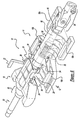
- Spring cassettes 31 a and 31 b include plastic internal guide tracks 33 which slidably support minor cassette 40 a, 40 b within the major cassette housings 32 .
- the tension springs 34 a and 34 b are wound springs wound around a central cylinder 36 through which the mounting pins 26 a and 26 b are slidably received.
- the mounting pins 26 a, 26 b are not fixedly attached to the main body 20 of the rearward bracket member 18 , however they are fixedly attached to the mounting pillars 28 a and 28 b which are a part of the forward bracket member 11 .
- the rearward bracket member 18 is allowed to move axially relative to the forward member 11 .
- the mounting pins 26 a and 26 b support the minor cassette 40 a, 40 b while the tension springs 34 a and 34 b translate a force to the rearward bracket member 18 thus assisting movement of the rearward bracket member 18 .
- the lever 22 allows the user to selectively engage and disengage locking pin 42 from a plurality of positioning slots 43 spaced axially along main body 20 .
- Lever 22 is pivotally or otherwise connected to the mounting pillar 28 to allow activation of said lever in a pre-selected direction to cause pin 42 to disengage from slot 43 .
- the positioning pin 42 is disengaged the rearward bracket member 18 may be repositioned relative to the forward bracket member 11 . Once a comfortable position is selected by the user the positioning pin 42 is re-engaged in a new positioning slot 43 .
- a plurality of positioning slots 43 may be created in the main body 20 of the forward bracket member 11 to allow for a plurality of select
Abstract
Description
Claims (11)
Priority Applications (1)
| Application Number | Priority Date | Filing Date | Title |
|---|---|---|---|
| US09/665,753 US6364357B1 (en) | 2000-09-20 | 2000-09-20 | Telescoping steering column and bracket |
Applications Claiming Priority (1)
| Application Number | Priority Date | Filing Date | Title |
|---|---|---|---|
| US09/665,753 US6364357B1 (en) | 2000-09-20 | 2000-09-20 | Telescoping steering column and bracket |
Publications (1)
| Publication Number | Publication Date |
|---|---|
| US6364357B1 true US6364357B1 (en) | 2002-04-02 |
Family
ID=24671440
Family Applications (1)
| Application Number | Title | Priority Date | Filing Date |
|---|---|---|---|
| US09/665,753 Expired - Lifetime US6364357B1 (en) | 2000-09-20 | 2000-09-20 | Telescoping steering column and bracket |
Country Status (1)
| Country | Link |
|---|---|
| US (1) | US6364357B1 (en) |
Cited By (8)
| Publication number | Priority date | Publication date | Assignee | Title |
|---|---|---|---|---|
| US20030209897A1 (en) * | 2002-05-09 | 2003-11-13 | Manwaring Marvin V. | Telescoping steering column assembly |
| US20040123695A1 (en) * | 2002-10-15 | 2004-07-01 | Knott Jeffrey A. | Steering wheel tilt mechanism |
| US20050070365A1 (en) * | 2003-09-30 | 2005-03-31 | Riefe Richard K. | Bushing for telescoping steering column assembly |
| US20050151362A1 (en) * | 2004-01-09 | 2005-07-14 | Mirjana Jurik | Steering column damping pad |
| US20060033319A1 (en) * | 2004-08-10 | 2006-02-16 | Lee Tinnin | Low-mounted column rake spring |
| US20060097501A1 (en) * | 2003-05-27 | 2006-05-11 | Shin Yoshimoto | Telescopic structure and steering column device for motor vehicle |
| US20110238040A1 (en) * | 2006-10-30 | 2011-09-29 | Medtronic, Inc. | Infusion catheter with composite tip |
| US20170066467A1 (en) * | 2015-09-09 | 2017-03-09 | Steering Solutions Ip Holding Corporation | Steering column assembly |
Citations (17)
| Publication number | Priority date | Publication date | Assignee | Title |
|---|---|---|---|---|
| US4541299A (en) * | 1983-03-14 | 1985-09-17 | Toyota Jidosha Kabushiki Kaisha | Steering shaft assembly for automotive vehicles |
| US4972732A (en) * | 1988-11-29 | 1990-11-27 | Trw Inc. | Tilt-telescope steering column |
| US5199319A (en) | 1991-02-15 | 1993-04-06 | Kabushiki Kaisha Yamada Seisakusho | Tilt telescopic steering device |
| US5242195A (en) * | 1990-11-29 | 1993-09-07 | Stabilus Gmbh | Telescopically length variable steering column |
| US5269562A (en) | 1991-02-06 | 1993-12-14 | Mercedes-Benz Ag | Axially adjustable steering column for vehicles |
| US5332260A (en) | 1989-09-12 | 1994-07-26 | Stabilus Gmbh | Telescopically length variable steering column arrangement |
| US5363716A (en) | 1993-04-01 | 1994-11-15 | Trw Inc. | Tilt-telescope steering column |
| US5449199A (en) * | 1992-10-22 | 1995-09-12 | Stabilus Gmbh | Steering assembly for a motor vehicle |
| US5481937A (en) | 1993-11-27 | 1996-01-09 | Lemforder Metallwaren Ag | Telescopic steering column for motor vehicles |
| US5802926A (en) * | 1997-03-21 | 1998-09-08 | Chrysler Corporation | Collapsible steering column assembly |
| US5813289A (en) | 1996-05-14 | 1998-09-29 | Trw Inc. | Steering column |
| US5820163A (en) | 1996-07-08 | 1998-10-13 | Ford Global Technologies, Inc. | Tilting, telescoping and energy absorbing steering column |
| US5870930A (en) | 1996-09-03 | 1999-02-16 | Means Industries | Steering column assembly |
| US5890397A (en) * | 1997-02-24 | 1999-04-06 | New Holland North America, Inc. | Four-way adjustable pedestal floor mounted steering column for a combine harvester |
| US5902186A (en) | 1997-08-08 | 1999-05-11 | Douglas Autotech Corp. | Intermediate shaft assembly for steering columns |
| US6035740A (en) | 1995-10-14 | 2000-03-14 | Zf Friedrichshafen Ag | Steering column of a motor vehicle |
| US6134983A (en) * | 1999-05-06 | 2000-10-24 | Delphi Technologies, Inc. | Motor vehicle steering column and method |
-
2000
- 2000-09-20 US US09/665,753 patent/US6364357B1/en not_active Expired - Lifetime
Patent Citations (17)
| Publication number | Priority date | Publication date | Assignee | Title |
|---|---|---|---|---|
| US4541299A (en) * | 1983-03-14 | 1985-09-17 | Toyota Jidosha Kabushiki Kaisha | Steering shaft assembly for automotive vehicles |
| US4972732A (en) * | 1988-11-29 | 1990-11-27 | Trw Inc. | Tilt-telescope steering column |
| US5332260A (en) | 1989-09-12 | 1994-07-26 | Stabilus Gmbh | Telescopically length variable steering column arrangement |
| US5242195A (en) * | 1990-11-29 | 1993-09-07 | Stabilus Gmbh | Telescopically length variable steering column |
| US5269562A (en) | 1991-02-06 | 1993-12-14 | Mercedes-Benz Ag | Axially adjustable steering column for vehicles |
| US5199319A (en) | 1991-02-15 | 1993-04-06 | Kabushiki Kaisha Yamada Seisakusho | Tilt telescopic steering device |
| US5449199A (en) * | 1992-10-22 | 1995-09-12 | Stabilus Gmbh | Steering assembly for a motor vehicle |
| US5363716A (en) | 1993-04-01 | 1994-11-15 | Trw Inc. | Tilt-telescope steering column |
| US5481937A (en) | 1993-11-27 | 1996-01-09 | Lemforder Metallwaren Ag | Telescopic steering column for motor vehicles |
| US6035740A (en) | 1995-10-14 | 2000-03-14 | Zf Friedrichshafen Ag | Steering column of a motor vehicle |
| US5813289A (en) | 1996-05-14 | 1998-09-29 | Trw Inc. | Steering column |
| US5820163A (en) | 1996-07-08 | 1998-10-13 | Ford Global Technologies, Inc. | Tilting, telescoping and energy absorbing steering column |
| US5870930A (en) | 1996-09-03 | 1999-02-16 | Means Industries | Steering column assembly |
| US5890397A (en) * | 1997-02-24 | 1999-04-06 | New Holland North America, Inc. | Four-way adjustable pedestal floor mounted steering column for a combine harvester |
| US5802926A (en) * | 1997-03-21 | 1998-09-08 | Chrysler Corporation | Collapsible steering column assembly |
| US5902186A (en) | 1997-08-08 | 1999-05-11 | Douglas Autotech Corp. | Intermediate shaft assembly for steering columns |
| US6134983A (en) * | 1999-05-06 | 2000-10-24 | Delphi Technologies, Inc. | Motor vehicle steering column and method |
Cited By (13)
| Publication number | Priority date | Publication date | Assignee | Title |
|---|---|---|---|---|
| WO2003099631A1 (en) | 2002-05-09 | 2003-12-04 | Delphi Technologies, Inc. | Telescoping steering column assembly |
| US6948741B2 (en) | 2002-05-09 | 2005-09-27 | Delphi Technologies, Inc. | Telescoping steering column assembly |
| US20030209897A1 (en) * | 2002-05-09 | 2003-11-13 | Manwaring Marvin V. | Telescoping steering column assembly |
| US20040123695A1 (en) * | 2002-10-15 | 2004-07-01 | Knott Jeffrey A. | Steering wheel tilt mechanism |
| US7441807B2 (en) * | 2003-05-27 | 2008-10-28 | Nsk Ltd. | Telescopic structure and steering column device for motor vehicle |
| US20060097501A1 (en) * | 2003-05-27 | 2006-05-11 | Shin Yoshimoto | Telescopic structure and steering column device for motor vehicle |
| US20050070365A1 (en) * | 2003-09-30 | 2005-03-31 | Riefe Richard K. | Bushing for telescoping steering column assembly |
| US20050151362A1 (en) * | 2004-01-09 | 2005-07-14 | Mirjana Jurik | Steering column damping pad |
| US20060033319A1 (en) * | 2004-08-10 | 2006-02-16 | Lee Tinnin | Low-mounted column rake spring |
| US7475907B2 (en) * | 2004-08-10 | 2009-01-13 | Delphi Technologies, Inc. | Low-mounted column rake spring |
| US20110238040A1 (en) * | 2006-10-30 | 2011-09-29 | Medtronic, Inc. | Infusion catheter with composite tip |
| US20170066467A1 (en) * | 2015-09-09 | 2017-03-09 | Steering Solutions Ip Holding Corporation | Steering column assembly |
| US9862404B2 (en) * | 2015-09-09 | 2018-01-09 | Steering Solutions Ip Holding Corporation | Steering column assembly |
Similar Documents
| Publication | Publication Date | Title |
|---|---|---|
| US7097205B2 (en) | Vehicle steering assembly | |
| EP2085291B1 (en) | Position adjusting device for steering wheel | |
| US6364357B1 (en) | Telescoping steering column and bracket | |
| US8157320B2 (en) | Headrest and vehicle seat provided with the same | |
| CN106004978B (en) | Transfer | |
| US8316737B2 (en) | Electric clamping device for an adjustable motor vehicle steering column | |
| US5172601A (en) | Drive nut and screw for seat adjuster | |
| JP5999767B2 (en) | Steering device | |
| US20030164608A1 (en) | Automotive steering system | |
| US11084519B2 (en) | Steering device | |
| US6619155B2 (en) | Adjustable pedal apparatus | |
| US20040231450A1 (en) | Impact absorbing structure for vehicle steering systems | |
| JP2021046000A (en) | Vehicle steering device | |
| US20140260758A1 (en) | Steering column assembly with improved attachment to a vehicle structure | |
| US6971676B2 (en) | Device for absorbing energy from an automobile vehicle steering column | |
| US4424721A (en) | Adjustable steering column | |
| JP4740768B2 (en) | Automatic transmission operation input device | |
| EP1905665A2 (en) | Infinitley adjustable steering column assembly | |
| JP4395006B2 (en) | Steering column position adjustment device | |
| KR100764172B1 (en) | Tilt And Telescope Steering System Equipped with Tube Tightening Apparatus | |
| JP2001341619A (en) | Parking lock device for transmission | |
| EP1630066A2 (en) | Dual axis rolling element for adjustable steering column | |
| JP3541858B2 (en) | Automobile steering column mounting structure | |
| JP2005133435A (en) | Door module | |
| JP3740723B2 (en) | Cable type column shift lever device |
Legal Events
| Date | Code | Title | Description |
|---|---|---|---|
| AS | Assignment |
Owner name: DAIMLERCHRYSLER CORPORATION, MICHIGAN Free format text: ASSIGNMENT OF ASSIGNORS INTEREST;ASSIGNORS:JURIK, MIRJANA;HOFMEISTER, KURT E.;STOIBER, JOHN M.;AND OTHERS;REEL/FRAME:011106/0409;SIGNING DATES FROM 20000817 TO 20000906 |
|
| STCF | Information on status: patent grant |
Free format text: PATENTED CASE |
|
| FPAY | Fee payment |
Year of fee payment: 4 |
|
| AS | Assignment |
Owner name: WILMINGTON TRUST COMPANY, DELAWARE Free format text: GRANT OF SECURITY INTEREST IN PATENT RIGHTS - FIRST PRIORITY;ASSIGNOR:CHRYSLER LLC;REEL/FRAME:019773/0001 Effective date: 20070803 Owner name: WILMINGTON TRUST COMPANY,DELAWARE Free format text: GRANT OF SECURITY INTEREST IN PATENT RIGHTS - FIRST PRIORITY;ASSIGNOR:CHRYSLER LLC;REEL/FRAME:019773/0001 Effective date: 20070803 |
|
| AS | Assignment |
Owner name: WILMINGTON TRUST COMPANY, DELAWARE Free format text: GRANT OF SECURITY INTEREST IN PATENT RIGHTS - SECOND PRIORITY;ASSIGNOR:CHRYSLER LLC;REEL/FRAME:019767/0810 Effective date: 20070803 Owner name: WILMINGTON TRUST COMPANY,DELAWARE Free format text: GRANT OF SECURITY INTEREST IN PATENT RIGHTS - SECOND PRIORITY;ASSIGNOR:CHRYSLER LLC;REEL/FRAME:019767/0810 Effective date: 20070803 |
|
| AS | Assignment |
Owner name: DAIMLERCHRYSLER COMPANY LLC, MICHIGAN Free format text: CHANGE OF NAME;ASSIGNOR:DAIMLERCHRYSLER CORPORATION;REEL/FRAME:021779/0793 Effective date: 20070329 |
|
| AS | Assignment |
Owner name: CHRYSLER LLC, MICHIGAN Free format text: CHANGE OF NAME;ASSIGNOR:DAIMLERCHRYSLER COMPANY LLC;REEL/FRAME:021826/0001 Effective date: 20070727 |
|
| AS | Assignment |
Owner name: US DEPARTMENT OF THE TREASURY, DISTRICT OF COLUMBI Free format text: GRANT OF SECURITY INTEREST IN PATENT RIGHTS - THIR;ASSIGNOR:CHRYSLER LLC;REEL/FRAME:022259/0188 Effective date: 20090102 Owner name: US DEPARTMENT OF THE TREASURY,DISTRICT OF COLUMBIA Free format text: GRANT OF SECURITY INTEREST IN PATENT RIGHTS - THIR;ASSIGNOR:CHRYSLER LLC;REEL/FRAME:022259/0188 Effective date: 20090102 |
|
| AS | Assignment |
Owner name: CHRYSLER LLC, MICHIGAN Free format text: RELEASE BY SECURED PARTY;ASSIGNOR:US DEPARTMENT OF THE TREASURY;REEL/FRAME:022902/0310 Effective date: 20090608 Owner name: CHRYSLER LLC,MICHIGAN Free format text: RELEASE BY SECURED PARTY;ASSIGNOR:US DEPARTMENT OF THE TREASURY;REEL/FRAME:022902/0310 Effective date: 20090608 |
|
| AS | Assignment |
Owner name: CHRYSLER LLC, MICHIGAN Free format text: RELEASE OF SECURITY INTEREST IN PATENT RIGHTS - FIRST PRIORITY;ASSIGNOR:WILMINGTON TRUST COMPANY;REEL/FRAME:022910/0498 Effective date: 20090604 Owner name: CHRYSLER LLC, MICHIGAN Free format text: RELEASE OF SECURITY INTEREST IN PATENT RIGHTS - SECOND PRIORITY;ASSIGNOR:WILMINGTON TRUST COMPANY;REEL/FRAME:022910/0740 Effective date: 20090604 Owner name: NEW CARCO ACQUISITION LLC, MICHIGAN Free format text: ASSIGNMENT OF ASSIGNORS INTEREST;ASSIGNOR:CHRYSLER LLC;REEL/FRAME:022915/0001 Effective date: 20090610 Owner name: THE UNITED STATES DEPARTMENT OF THE TREASURY, DIST Free format text: SECURITY AGREEMENT;ASSIGNOR:NEW CARCO ACQUISITION LLC;REEL/FRAME:022915/0489 Effective date: 20090610 Owner name: CHRYSLER LLC,MICHIGAN Free format text: RELEASE OF SECURITY INTEREST IN PATENT RIGHTS - FIRST PRIORITY;ASSIGNOR:WILMINGTON TRUST COMPANY;REEL/FRAME:022910/0498 Effective date: 20090604 Owner name: CHRYSLER LLC,MICHIGAN Free format text: RELEASE OF SECURITY INTEREST IN PATENT RIGHTS - SECOND PRIORITY;ASSIGNOR:WILMINGTON TRUST COMPANY;REEL/FRAME:022910/0740 Effective date: 20090604 Owner name: NEW CARCO ACQUISITION LLC,MICHIGAN Free format text: ASSIGNMENT OF ASSIGNORS INTEREST;ASSIGNOR:CHRYSLER LLC;REEL/FRAME:022915/0001 Effective date: 20090610 Owner name: THE UNITED STATES DEPARTMENT OF THE TREASURY,DISTR Free format text: SECURITY AGREEMENT;ASSIGNOR:NEW CARCO ACQUISITION LLC;REEL/FRAME:022915/0489 Effective date: 20090610 |
|
| AS | Assignment |
Owner name: CHRYSLER GROUP LLC, MICHIGAN Free format text: CHANGE OF NAME;ASSIGNOR:NEW CARCO ACQUISITION LLC;REEL/FRAME:022919/0126 Effective date: 20090610 Owner name: CHRYSLER GROUP LLC,MICHIGAN Free format text: CHANGE OF NAME;ASSIGNOR:NEW CARCO ACQUISITION LLC;REEL/FRAME:022919/0126 Effective date: 20090610 |
|
| FPAY | Fee payment |
Year of fee payment: 8 |
|
| AS | Assignment |
Owner name: CHRYSLER GROUP LLC, MICHIGAN Free format text: RELEASE BY SECURED PARTY;ASSIGNOR:THE UNITED STATES DEPARTMENT OF THE TREASURY;REEL/FRAME:026343/0298 Effective date: 20110524 Owner name: CHRYSLER GROUP GLOBAL ELECTRIC MOTORCARS LLC, NORT Free format text: RELEASE BY SECURED PARTY;ASSIGNOR:THE UNITED STATES DEPARTMENT OF THE TREASURY;REEL/FRAME:026343/0298 Effective date: 20110524 |
|
| AS | Assignment |
Owner name: CITIBANK, N.A., NEW YORK Free format text: SECURITY AGREEMENT;ASSIGNOR:CHRYSLER GROUP LLC;REEL/FRAME:026404/0123 Effective date: 20110524 |
|
| AS | Assignment |
Owner name: CITIBANK, N.A., NEW YORK Free format text: SECURITY AGREEMENT;ASSIGNOR:CHRYSLER GROUP LLC;REEL/FRAME:026435/0652 Effective date: 20110524 |
|
| FPAY | Fee payment |
Year of fee payment: 12 |
|
| AS | Assignment |
Owner name: JPMORGAN CHASE BANK, N.A., ILLINOIS Free format text: SECURITY AGREEMENT;ASSIGNOR:CHRYSLER GROUP LLC;REEL/FRAME:032384/0640 Effective date: 20140207 |
|
| AS | Assignment |
Owner name: FCA US LLC, MICHIGAN Free format text: CHANGE OF NAME;ASSIGNOR:CHRYSLER GROUP LLC;REEL/FRAME:035553/0356 Effective date: 20141203 |
|
| AS | Assignment |
Owner name: FCA US LLC, FORMERLY KNOWN AS CHRYSLER GROUP LLC, Free format text: RELEASE OF SECURITY INTEREST RELEASING SECOND-LIEN SECURITY INTEREST PREVIOUSLY RECORDED AT REEL 026426 AND FRAME 0644, REEL 026435 AND FRAME 0652, AND REEL 032384 AND FRAME 0591;ASSIGNOR:CITIBANK, N.A.;REEL/FRAME:037784/0001 Effective date: 20151221 |
|
| AS | Assignment |
Owner name: FCA US LLC (FORMERLY KNOWN AS CHRYSLER GROUP LLC), Free format text: RELEASE BY SECURED PARTY;ASSIGNOR:CITIBANK, N.A.;REEL/FRAME:042885/0255 Effective date: 20170224 |
|
| AS | Assignment |
Owner name: FCA US LLC (FORMERLY KNOWN AS CHRYSLER GROUP LLC), Free format text: RELEASE BY SECURED PARTY;ASSIGNOR:JPMORGAN CHASE BANK, N.A.;REEL/FRAME:048177/0356 Effective date: 20181113 |