US6339482B1 - Control method for positioning multiple lens of scanner - Google Patents
Control method for positioning multiple lens of scanner Download PDFInfo
- Publication number
- US6339482B1 US6339482B1 US09/164,423 US16442398A US6339482B1 US 6339482 B1 US6339482 B1 US 6339482B1 US 16442398 A US16442398 A US 16442398A US 6339482 B1 US6339482 B1 US 6339482B1
- Authority
- US
- United States
- Prior art keywords
- lens
- pixel
- marks
- positioning
- ccd
- Prior art date
- Legal status (The legal status is an assumption and is not a legal conclusion. Google has not performed a legal analysis and makes no representation as to the accuracy of the status listed.)
- Expired - Fee Related
Links
Images


Classifications
-
- H—ELECTRICITY
- H04—ELECTRIC COMMUNICATION TECHNIQUE
- H04N—PICTORIAL COMMUNICATION, e.g. TELEVISION
- H04N1/00—Scanning, transmission or reproduction of documents or the like, e.g. facsimile transmission; Details thereof
- H04N1/04—Scanning arrangements, i.e. arrangements for the displacement of active reading or reproducing elements relative to the original or reproducing medium, or vice versa
- H04N1/047—Detection, control or error compensation of scanning velocity or position
-
- H—ELECTRICITY
- H04—ELECTRIC COMMUNICATION TECHNIQUE
- H04N—PICTORIAL COMMUNICATION, e.g. TELEVISION
- H04N2201/00—Indexing scheme relating to scanning, transmission or reproduction of documents or the like, and to details thereof
- H04N2201/04—Scanning arrangements
- H04N2201/047—Detection, control or error compensation of scanning velocity or position
- H04N2201/04701—Detection of scanning velocity or position
- H04N2201/04715—Detection of scanning velocity or position by detecting marks or the like, e.g. slits
- H04N2201/04717—Detection of scanning velocity or position by detecting marks or the like, e.g. slits on the scanned sheet, e.g. a reference sheet
Definitions
- the present invention relates to a control method of switching multiple lens of a document image scanner, and particularly to a closed-loop control method which ensures the scanned image to be focused correctly by controlling each lens of different magnification positioning accurately to its correct position.
- FIG. 1 is a multiple lens switching mechanism of the prior art.
- the mechanism utilizes a motor 12 and reduction gears 14 to switch a set of lenses 18 mounted on a sliding rack 16 to some specific positions aligning to an opto-electric module, and thus providing various image resolutions.
- FIG. 2 is another prior art scanner with dual-lens mechanism.
- a lever mechanism 22 moves a dual-lens base 24 sliding on a rail 26 to change the lenses and image resolutions.
- FIG. 3 is further a scanner of prior arts with dual-lens and a movable reflector mechanism.
- the images of two different kinds of documents 34 and 36 are taken by two lenses 38 individually and reflected by a reflector 32 selectively moving into one of the two optical paths for transmitting the image into the opto-electric module.
- the multiple lens systems of prior arts are emphasized not on the control method but on the positioning or moving mechanisms of the lens.
- the control methods of prior arts for positioning the lens are generally of mechanical manners.
- the common methods are using stoppers or position detectors for the lens to stop at their predetermined position after moving.
- this “open-loop” control method relies on precise fabrication of mechanical components; otherwise, the mispositioning of the lens will occur.
- a mechanical “open-loop” control method cannot ensure a reliable positioning.
- the present invention provides a control method for positioning multiple lens of a scanner to their accurate position.
- the method mainly uses a linear reference image, such as a calibration paper with some marks in the linear scanning range, taken by a specific lens to the CCD for deciding if the lens is well positioned.
- the decision is made by one of the following three methods:
- the lens is controlled to move to the correct position by the continuous feedback signals from the CCD, so the accuracy and reliability of the positioning can be kept without being influenced from any worn-out of frequent movements of the mechanism.
- FIG. 1 is a perspective view of a conventional lens switching mechanism for a multiple lens scanner
- FIG. 2 is another scanner of prior arts with dual-lens mechanism
- FIG. 3 is further a scanner of prior arts with dual-lens and a movable reflector mechanism
- FIG. 4 is a schematic view showing a first embodiment of the present invention which uses a control method of taking the absolute image position on a CCD for a mark on a calibration paper;
- FIG. 5 is a flow chart of the control method of FIG. 4;
- FIG. 6 is a schematic view showing a second embodiment of the present invention which uses a control method of taking the relative image positions on a CCD for two marks on a calibration paper;
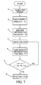
- FIG. 7 is a flow chart of the control method of FIG. 6;
- FIG. 8 is a schematic view showing a third embodiment of the present invention which uses a control method of taking the image position range on a CCD for two marks on a calibration paper;
- FIG. 9 is a flowchart of the control method of FIG. 8 .
- FIGS. 1, 2 and 3 Some conventional mechanisms for switching the lenses of a multiple lens scanner are described above in accompany with FIGS. 1, 2 and 3 .
- FIG. 4 a schematic view of a first embodiment of the present invention is shown.
- the method for positioning a specific lens of a multiple lens scanner is taking the absolute image position on a CCD for a mark on a calibration paper.
- a mark 44 is made on a calibration paper 42 , such as a black mark on a white paper or by other identification marking manner.
- the lens switching mechanism is started from where the lens rests.
- a pixel n i identified as a waveform
- the lens will be controlled to move leftward as indicated by the arrow to a correct position 46 where the image of the mark 44 is positioned at a pixel N i of the CCD 48 .
- the position of the mark 44 on the calibration paper 42 which is imaged on the CCD 48 is recorded as a standard pixel when the lens is adjusted to a correct position 46 .
- the standard pixel can be used as an index for positioning the lens.
- a precise positioning of the lens can be made. So, as the lens is at the position 46 ′, the mark 44 is imaged at the pixel n i which is different from the standard pixel N i , i.e. n i >N i .
- the lens is then controlled by a control unit (not shown) to move in a direction toward the correct position 46 for minimizing the difference; otherwise, if the lens is at another position where n i ⁇ N i , the lens is then controlled to move in another direction toward the correct position 46 also for minimizing the difference.
- the movement control continues and the lens moves until the difference is reduced to an acceptable range, i.e.
- FIG. 5 a flow chart illustrates the steps of the method described in FIG. 4 for calibration and movement control of a lens in a multiple lens scanner. These steps includes:
- FIG. 6 a schematic view of a second embodiment of the present invention is shown.
- the method for positioning a specific lens of a multiple lens scanner is taking the relative image positions on a CCD for two marks on a calibration media.
- two marks 44 and 45 are made on a calibration paper 42 , such as two black marks on a white paper or by other identification marking manner.
- the lens switching is started from where the lens rests.
- the lens will be controlled to move leftward as indicated by the arrow to a correct position 46 where the images of the marks 44 and 45 are positioned at two correct pixels N i and N j of CCD 48 .
- the relative position of the correct pixels N i and N j relative to two reference pixels, such as the first pixel and the last pixel of the CCD 48 are recorded as two standard differential values N f and N r for positioning the lens.
- the value N f represents the differential value of the pixels N i to the first pixel and the value N r represents the differential value of the pixels N j to the last pixel.
- the values N f and N r have a specific relationship, for example, by arranging the two marks 44 and 45 with equal distances L to two edges of the paper 42 , and N f is equal to N r when the lens is at the correct position 46 .
- the standard differential value N f and N r can be used as indexes for positioning the lens.
- N f and N r can be used as indexes for positioning the lens.
- the lens by monitoring the image positions of the marks 44 and 45 by the pixels n i and n j on the CCD 48 and calculating the differential values n f and n r (relative to the first and the last pixel respectively) to check if they are equal to N f and N r respectively, a precise positioning of the lens can be made. So, as the lens is at the position 46 ′, the marks 44 and 45 are imaged at the pixels n i and n j and with unequal differential values n f and n r , i.e.
- the lens is then controlled by a control unit (not shown) to move in a direction toward the correct position 46 for equalizing the differential values n f and n r ; otherwise, if the lens is at another position where n f ⁇ n r , the lens is then controlled to move in another direction toward the correct position 46 also for equalizing the differential values n f and n r .
- the movement control continues and the lens moves until the difference is reduced to an acceptable range, i.e.
- FIG. 7 a flow chart illustrates the steps of the method described in FIG. 6 for calibration and movement control of a lens in a multiple lens scanner. The steps includes:
- c) Recording a first standard differential value between the pixels of the first mark and first reference point, and a second standard differential value between the pixels of the second mark and the second reference point, for example, the first standard differential value N f taken from the pixel N i and the first pixel on the CCD, the second standard differential value N r taken from the pixel N j and the last pixel on the CCD, and the two values N f and N r are arranged to be equal;
- a first and a second instant pixels of the CCD on which the first and second marks are imaged through the lens that moves to a certain position for example, a number n i and a number n j pixels on a CCD
- a first and a second instant differential values between the first and second instant pixels and the first and second reference pixels of the CCD respectively for example, a first instant differential value n f taken from the first instant pixel n i and the first pixel on the CCD, and a second differential value n r taken from the second instant pixel n j and the last pixel on the CCD;
- FIG. 8 a schematic view of a third embodiment of the present invention is shown.
- the method for positioning a specific lens of a multiple lens scanner is taking the image range on a CCD for two marks on a calibration paper.
- two marks 44 and 45 are made on a calibration paper 42 , such as two black marks on a white paper or by other identification marking manner.
- the two marks 44 and 45 locate apart with a distance L.
- the images of the marks 44 and 45 are imaged on two correct pixels N i and N j (identified as waveforms) of a CCD 48 , the standard differential value N l between the two pixels are recorded as an index for positioning the lens.
- the lens switching is started from where the lens rests.
- the lens is then controlled by an unshown control unit to move in a direction as shown by the arrow toward the correct position 46 for approaching the differential value n l to the standard differential value N l .
- the movement control continues and the lens moves until the difference is reduced to an acceptable range, i.e.
- FIG. 9 a flow chart illustrates the steps of the method described in FIG. 8 for calibration and movement control of a lens in a multiple lens scanner. The steps includes:
Abstract
Description
Claims (19)
Priority Applications (1)
| Application Number | Priority Date | Filing Date | Title |
|---|---|---|---|
| US09/164,423 US6339482B1 (en) | 1998-09-30 | 1998-09-30 | Control method for positioning multiple lens of scanner |
Applications Claiming Priority (1)
| Application Number | Priority Date | Filing Date | Title |
|---|---|---|---|
| US09/164,423 US6339482B1 (en) | 1998-09-30 | 1998-09-30 | Control method for positioning multiple lens of scanner |
Publications (1)
| Publication Number | Publication Date |
|---|---|
| US6339482B1 true US6339482B1 (en) | 2002-01-15 |
Family
ID=22594414
Family Applications (1)
| Application Number | Title | Priority Date | Filing Date |
|---|---|---|---|
| US09/164,423 Expired - Fee Related US6339482B1 (en) | 1998-09-30 | 1998-09-30 | Control method for positioning multiple lens of scanner |
Country Status (1)
| Country | Link |
|---|---|
| US (1) | US6339482B1 (en) |
Cited By (2)
| Publication number | Priority date | Publication date | Assignee | Title |
|---|---|---|---|---|
| US20030210442A1 (en) * | 2002-05-10 | 2003-11-13 | Thomas Sheng | Adjustable optical mechanism |
| US20040165286A1 (en) * | 2001-10-10 | 2004-08-26 | Masashi Matsumoto | Image reader |
Citations (1)
| Publication number | Priority date | Publication date | Assignee | Title |
|---|---|---|---|---|
| US5841121A (en) * | 1988-08-31 | 1998-11-24 | Norand Technology Corporation | Hand-held optically readable character set reader having automatic focus control for operation over a range of distances |
-
1998
- 1998-09-30 US US09/164,423 patent/US6339482B1/en not_active Expired - Fee Related
Patent Citations (1)
| Publication number | Priority date | Publication date | Assignee | Title |
|---|---|---|---|---|
| US5841121A (en) * | 1988-08-31 | 1998-11-24 | Norand Technology Corporation | Hand-held optically readable character set reader having automatic focus control for operation over a range of distances |
Cited By (3)
| Publication number | Priority date | Publication date | Assignee | Title |
|---|---|---|---|---|
| US20040165286A1 (en) * | 2001-10-10 | 2004-08-26 | Masashi Matsumoto | Image reader |
| US7327499B2 (en) * | 2001-10-10 | 2008-02-05 | Pfu Limited | Image reading apparatus |
| US20030210442A1 (en) * | 2002-05-10 | 2003-11-13 | Thomas Sheng | Adjustable optical mechanism |
Similar Documents
| Publication | Publication Date | Title |
|---|---|---|
| US4724330A (en) | Self aligning raster input scanner | |
| CA2077832C (en) | Method and apparatus for image registration in a single pass ros system | |
| US5663806A (en) | Non-destructive target marking for image stitching | |
| JPH04277772A (en) | Method and apparatus for lateral positioning of image on photographic light sensitive body belt | |
| EP1227653B1 (en) | Image reading apparatus | |
| US5719404A (en) | Method and apparatus for calibrating the horizontal starting point of a document on a flatbed scanner | |
| US6339482B1 (en) | Control method for positioning multiple lens of scanner | |
| US5321434A (en) | Digital color printer with improved lateral registration | |
| US4424534A (en) | Original reader | |
| US6147343A (en) | Photoelectric imaging method and apparatus | |
| EP0814421B1 (en) | Image reading apparatus | |
| US5973814A (en) | Optical document scanning method and apparatus with adjustable scanning magnification | |
| JPS60154769A (en) | Method for correcting shading in optical reader | |
| JP4018255B2 (en) | Defocus amount detection method for optical unit and optical unit adjustment device | |
| EP2056581B1 (en) | Image reading device and document reading device | |
| US20020131060A1 (en) | Process and apparatus for the digital production of a picture | |
| JP3461993B2 (en) | Optical scanning device | |
| JP4249849B2 (en) | Image reading apparatus misalignment diagnosis method | |
| US20100195121A1 (en) | Adjusting measurements | |
| EP1595705A2 (en) | Apparatus for and method of recording image | |
| US6529292B1 (en) | Apparatus and method for locating an optical module of an image-scanning system | |
| JP3584608B2 (en) | Image reading device | |
| JP4098175B2 (en) | Image reading apparatus and assembly method thereof | |
| JPH06224101A (en) | Bifocal lens and alignment device | |
| CN1101564C (en) | Method for controlling multi-lens shift mechanism |
Legal Events
| Date | Code | Title | Description |
|---|---|---|---|
| AS | Assignment |
Owner name: MUSTEK SYSTEMS INC., TAIWAN Free format text: ASSIGNMENT OF ASSIGNORS INTEREST;ASSIGNORS:TSAI, JEHN-TSAIR;CHANG, TE-CHIH;REEL/FRAME:009499/0453 Effective date: 19980831 |
|
| AS | Assignment |
Owner name: MUSTEK SYSTEMS INC., TAIWAN Free format text: ASSIGNMENT OF ASSIGNORS INTEREST;ASSIGNORS:TSAI, JEHN-TSAIR;CHANG, TE-CHIH;REEL/FRAME:009607/0060 Effective date: 19980831 |
|
| FPAY | Fee payment |
Year of fee payment: 4 |
|
| AS | Assignment |
Owner name: TRANSPACIFIC OPTICS LLC,DELAWARE Free format text: ASSIGNMENT OF ASSIGNORS INTEREST;ASSIGNOR:MUSTEK SYSTEMS, INC.;REEL/FRAME:017480/0325 Effective date: 20051202 Owner name: TRANSPACIFIC OPTICS LLC, DELAWARE Free format text: ASSIGNMENT OF ASSIGNORS INTEREST;ASSIGNOR:MUSTEK SYSTEMS, INC.;REEL/FRAME:017480/0325 Effective date: 20051202 |
|
| FPAY | Fee payment |
Year of fee payment: 8 |
|
| REMI | Maintenance fee reminder mailed | ||
| LAPS | Lapse for failure to pay maintenance fees | ||
| STCH | Information on status: patent discontinuation |
Free format text: PATENT EXPIRED DUE TO NONPAYMENT OF MAINTENANCE FEES UNDER 37 CFR 1.362 |
|
| FP | Lapsed due to failure to pay maintenance fee |
Effective date: 20140115 |
|
| AS | Assignment |
Owner name: HANGER SOLUTIONS, LLC, GEORGIA Free format text: ASSIGNMENT OF ASSIGNORS INTEREST;ASSIGNOR:INTELLECTUAL VENTURES ASSETS 161 LLC;REEL/FRAME:052159/0509 Effective date: 20191206 |
|
| AS | Assignment |
Owner name: INTELLECTUAL VENTURES ASSETS 161 LLC, DELAWARE Free format text: ASSIGNMENT OF ASSIGNORS INTEREST;ASSIGNOR:TRANSPACIFIC OPTICS LLC;REEL/FRAME:051974/0018 Effective date: 20191126 |