US6267802B1 - Composition apparatus and method for flue gas conditioning - Google Patents
Composition apparatus and method for flue gas conditioning Download PDFInfo
- Publication number
- US6267802B1 US6267802B1 US09/335,428 US33542899A US6267802B1 US 6267802 B1 US6267802 B1 US 6267802B1 US 33542899 A US33542899 A US 33542899A US 6267802 B1 US6267802 B1 US 6267802B1
- Authority
- US
- United States
- Prior art keywords
- gas stream
- organometallic compound
- composition
- metal
- particles
- Prior art date
- Legal status (The legal status is an assumption and is not a legal conclusion. Google has not performed a legal analysis and makes no representation as to the accuracy of the status listed.)
- Expired - Lifetime
Links
Images


Classifications
-
- B—PERFORMING OPERATIONS; TRANSPORTING
- B03—SEPARATION OF SOLID MATERIALS USING LIQUIDS OR USING PNEUMATIC TABLES OR JIGS; MAGNETIC OR ELECTROSTATIC SEPARATION OF SOLID MATERIALS FROM SOLID MATERIALS OR FLUIDS; SEPARATION BY HIGH-VOLTAGE ELECTRIC FIELDS
- B03C—MAGNETIC OR ELECTROSTATIC SEPARATION OF SOLID MATERIALS FROM SOLID MATERIALS OR FLUIDS; SEPARATION BY HIGH-VOLTAGE ELECTRIC FIELDS
- B03C3/00—Separating dispersed particles from gases or vapour, e.g. air, by electrostatic effect
- B03C3/01—Pretreatment of the gases prior to electrostatic precipitation
- B03C3/013—Conditioning by chemical additives, e.g. with SO3
Definitions
- the present invention is related generally to the conditioning of gas streams for particulate removal and specifically to the conditioning of gas streams for particulate removal using an electrostatic precipitator, particularly at high temperatures.
- An electrostatic precipitator is a commonly used device for removing undesired particles from the gas streams produced by plants and refineries.
- “undesired particles” refers to any particulate matter such as flyash, that is desired to be removed from a gas stream.
- undesired particle-laden gases pass negatively charged corona electrodes which impart a negative charge to the undesired particles. The charged particles then migrate towards positively charged collection plates and are removed by various techniques, including sonic horn blasts or rapping of the collection plates.
- Electrostatic precipitators may employ a common stage or separate stages for both the charging and collection of undesired particles.
- Cold-side electrostatic precipitators are located on the downstream side of the air preheater or heat exchanger (which transfers heat from the flue gas to the air to be fed into the furnace) and therefore operate at relatively low temperatures (i.e., temperatures of no more than about 200° C.).
- Hot-side electrostatic precipitators are located on the upstream side of the air preheater and therefore operate at relatively high temperatures (i.e., more than about 250° C.).
- Additives, such as sulfur trioxide, ammonia, and various surface conditioning additives (such as sulfuric acid) that are effective under cold-side conditions are generally ineffective under hot-side conditions because of different charge conduction mechanisms.
- surface conduction of charge is the predominant charge conduction mechanism while under hot-side conditions (which exist typically at operating temperatures more than the critical temperature) volume conduction of charge is the predominant charge conduction mechanism.
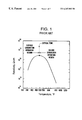
- critical temperature is the temperature corresponding to the highest attainable resistivity of an undesired particle (which is commonly located at the top of a bell-shaped curve as shown in FIG. 1 ).
- One conditioning method for controlling high temperature resistivity that has had some success under hot-side conditions has been bulk addition of sodium into the coal feed to the boiler.
- sodium is added to the coal feed as a sodium sulfate or soda ash.
- the sodium is co-fired with the coal in the boiler and is incorporated into the undesired particles as various sodium oxides.
- the bulk addition of sodium to the coal feed can cause serious problems, such as boiler slagging due to high sodium flyash, the consumption of excessive amounts of alkali material and a commensurate increase in operating costs, higher gas temperatures downstream of the boiler that can aggravate duct and electrostatic precipitator structural problems, and an inability to supply the additive on an intermittent or as-needed basis.
- Objectives of the present invention include providing an electrostatic precipitator that can remove sufficient undesired particles from a gas stream to comply with pertinent environmental regulations; increasing the efficiency of electrostatic precipitators in the removal of undesired particles from a gas stream, preferably without significantly increasing capital and operating costs and without undue power consumption; increasing electrostatic precipitator efficiency without the use of toxic additives; increasing electrostatic precipitator efficiency by methods and apparatuses that are readily adaptable to existing designs; and reducing undesired particle reentrainment during removal of undesired particles from a collection surface.
- Related objectives include increasing electrostatic precipitator efficiency without inducing boiler slagging, without excessive consumption of alkali material, without increasing gas stream temperatures downstream of the boiler, and using an additive that can be supplied on an intermittent or as-needed basis.
- a process for removing undesired solid particles from a gas stream that can realize these and other objectives.
- the process includes the steps of:
- agglomerate refers to a cluster or accumulation of undesired particles and/or particles of the organometallic compound or a derivative thereof;
- a “carboxylic acid” refers to any acid having both a carboxyl (hydroxyl (OH) and carbonyl (C ⁇ 0 )) group of the form R-COOH where R is a linked organic structure to the carboxylic group (COOH);
- a “collection surface” is any surface which collects undesired particles (e.g., an electrode or a porous filtration surface); and “contacting” refers to any technique for inputting the composition into the gas stream, such as by spray nozzles, drip emitters, venturi eductors and the like.
- the organometallic compound is preferably any organic compound that decomposes at the gas stream temperature to produce an inorganic metal oxide after injection into the gas stream.
- “Decomposition” refers to the constituents of the organometallic forming other compounds as a result of thermal or chemical decomposition, chemical reaction, or otherwise.
- the inorganic metal oxide is preferably an oxalate, carbonate, hydroxide, oxide and mixtures thereof with a carbonate and oxide being more preferred.
- the organometallic compound have a melting point that is less than and a boiling point that is more than (i.e., is substantially nonvaporizable or free of vaporization) at the temperature of the gas stream to produce a liquid additive of the injection and a relatively low molecular weight (i.e., preferably no more than about 180 daltons).
- the organometallic compound is a monocarboxylic acid (metal) salt and even more preferably the monocarboxylic acid salt has 3 or fewer carbon atoms (the carbon of the terminal group being counted as part of the chain) and is selected from the group consisting of a metal acetate, a metal formate, a metal propionate and mixtures thereof and even more preferably a metal acetate, a metal formate and mixtures thereof.
- a metal salt of a carboxylic acid is formed when a metal cation substitutes for the H in the carboxylic group.
- the formula for a metal salt of a carboxylic acid is R-COOM, where R is a linked organic structure and M is the metal.
- metal salts of carboxylic acids that can be decomposed at the gas stream temperature include sodium acetate, CH 3 COONa, and sodium formate, HCOONa.
- the temperature of the gas stream under hot-side conditions is typically at least about 250° C. (480° F.) and more typically ranges from about 270° C. (520° F.) to about 480° C. (900° F.).
- molecular decomposition of the organometallic compound at the gas stream temperature yields available metal ion charge carriers on the undesired particle(s) and/or releases the metal into the agglomerate which provides additional charge conduction capability to the agglomerate and thereby decreases resistivity and retards deterioration of electrostatic precipitator performance in response to high undesired particle resistivity.
- At least most of the metal(s) in the organometallic compound is preferably a monovalent alkaline earth metal and more preferably is sodium, potassium, lithium and mixtures thereof, with sodium, potassium, and mixtures thereof being even more preferred.
- the organometallic additive can thus be selected from, a number of widely available, inexpensive, nontoxic, and substantially noncorrosive compounds.
- the additive composition preferably includes a volatile carrier fluid, such as water, which vaporizes readily at the gas stream temperature (i.e., has a boiling point that is less than the gas stream temperature). It is preferred that substantially all of the carrier fluid vaporize before the salt or derivative(s) thereof contacts the collection surface, which is commonly within no more than about 5 seconds after contact of the composition with the gas stream.
- a volatile carrier fluid such as water
- the composition can further include a decomposition agent to cause decomposition of the carboxylic acid salt after contact thereof with the gas stream.
- a decomposition agent refers to any substance that lowers the temperature and/or increases the rate at which the salt decomposes into one or more other compounds and/or causes the salt to form desired products in the gas stream.
- the decomposition agent typically catalyzes thermal decomposition and/or reacts with the salt to form desired products.
- a decomposition agent such as NaOH can be employed to form the end products, metal carbonate and H 2 .
- the decomposition agent has a boiling point that is above the gas stream temperature. Otherwise when the blended additive is injected into the gas stream, substantial amounts of the decomposition agent may volatilize before the decomposition reaction is substantially completed. It is desired that the decomposition reaction occur either in the gas stream or after the additive particles are collected on the collection surface.
- Preferred decomposition agents include one or more alkali metal hydroxides.
- the additive composition can include one or more of the above-noted components.
- the additive composition includes at least about 1.7% by weight of the metal carboxylic acid salt, at least about 97.3% by weight of the carrier fluid, and at least about 1.0% by weight of the decomposition agent.
- an additive for improving charge conduction in electrostatically collected undesired solid particles includes:
- the additive can further include a decomposition agent to cause decomposition of the salt after contact of the salt with the gas stream.
- a particle removal process includes the steps of:
- the collection surface is located between a combustion zone where the gas stream is generated and a heat exchanger that transfers heat from the gas stream to an oxygen-containing gas to be introduced into the combustion zone.
- Another embodiment of the present invention is directed to a system for removing undesired particles from a gas stream that includes:
- a collection surface (such as a filtration surface or electrode) that is positioned in the housing between the input and the output to collect at least a portion of the undesired particles and at least a portion of the composition on the collection surface.
- the additive contacting means can be any device for contacting the additive composition, either in solid or liquid form, with the gas stream.
- the additive contacting means is one or more spray nozzles, drip emitters, venturi eductors and the like.
- a suitable control feedback circuit can be used to selectively control the addition of the additive to the gas stream in response to the resistivity of the collected undesired particles or an electrical parameter (i.e., voltage, current or resistance) of the electrostatic precipitator.
- the collection surface is a collecting electrode and the system further includes:
- At least one charging electrode electrically connected to a terminal of the power supply and positioned in the housing relative to the input gas stream to impart a charge to the undesired particles and composition particles in the input gas stream.
- the collecting electrode is electrically connected to the other of the terminals of the power supply and is positioned in the housing relative to the charging electrode to accumulate the charged particles on the collecting electrode.
- the additive of the present invention can have a number of advantages relative to existing additives, particularly under hot-side conditions.
- the electrostatic precipitator when the additive is added to the gas stream, the electrostatic precipitator, even under hotside conditions, can remove sufficient undesired particles to form a gas stream that is in compliance with pertinent environmental regulations.
- the additive permits the electrostatic precipitator to maintain a high level of particulate removal efficiency at a relatively low level of power consumption over time with no significant deterioration in electrostatic precipitator performance.
- the additive can be readily employed with existing electrostatic precipitators simply by retrofitting the precipitator with devices, such as nozzles or drip emitters, for injecting the additive into the gas stream.
- the injection of the additive into the gas stream upstream of the electrostatic precipitator rather than the addition of the additive to the coal feed substantially inhibits boiler slagging, avoids excessive consumption of the additive, and avoids increasing the gas stream temperature downstream of the boiler.
- FIG. 1 is a graph showing the relationship between particle temperature and particle resistivity for typical flyash particles
- FIG. 2 is a perspective view of an embodiment of the present invention in an electrostatic precipitator
- FIG. 3 is a cut away view along line A—A of FIG. 2 showing the additive injection device spraying droplets of the additive composition into the gas stream;
- FIG. 4 is a side view of a collection plate showing an accumulation of additive particles and undesired particles on the collection plate;
- FIG. 5 is a plot of undesired particle resistivity versus temperature for various additives
- FIG. 6 is a plot of undesired particle resistivity versus temperature for various additives
- FIG. 7 is a plot of undesired particle resistivity versus temperature for various additives.
- FIG. 8 is a plot of undesired particle resistivity versus temperature for various additives.
- FIGS. 2 and 3 depict an embodiment of the present invention as implemented in an electrostatic precipitator for removal of undesired particles such as fly ash from a gas stream.
- the electrostatic precipitator includes housing assembly 6 , precipitating assembly 8 , and additive injection assembly 10 .
- the housing assembly 6 includes an input duct 12 , one or more input plenums 14 , shell 16 , one or more hoppers 18 , one or more output plenums 20 , and output duct 22 .
- the precipitating assembly 8 includes a plurality of sections 24 .
- Each section 24 includes a plurality of alternately disposed discharge electrodes 26 and collection plates 28 , a corresponding plurality of electrical conductors 90 , and an interconnected power supply 32 .
- the negative and positive terminals of the power supply 32 are connected to the discharge electrodes 26 and collection plates 28 , respectively.
- the additive injection assembly 10 includes a reservoir (not shown) and an interconnected feed line 34 and plurality of nozzles 37 .
- the gas stream may be contacted with the additive composition continuously or intermittently and by many different methods.
- Additive injection assembly 10 achieves contacting by atomizing a composition including a carrier fluid and a carboxylic acid salt or a precursor thereof into the gas stream 36 in the form of droplets 38 .
- Atomization may be realized by a number of different methodologies including spraying the composition through a nozzle.
- electrostatic injection nozzles can be utilized.
- a carrier fluid is not required to disperse additive particles in the gas stream 36 .
- additive particles 40 may be simply dripped into the gas stream 36 by a suitable device (e.g., a drip emitter).
- additive injection assembly 10 should be located upstream of the precipitating assembly 8 .
- the additive injection assembly 10 is disposed so as to provide a sufficient distance between the additive injection assembly 10 and the nearest of the collection plates 28 such that, prior to contacting the nearest collection plate 28 , a substantial portion of the carrier fluid, preferably at least about 90% and more preferably at least about 95% by weight, has separated from the additive and a substantially uniform dispersion of additive particles 40 across the gas stream 36 has been attained.
- the preferred Mean Sauter Diameter of the droplets 38 upon injection into the gas stream is from about 10 to about 100 micrometers and of the droplets 38 a after vaporization of the carrier fluid from about 1 to about 10 micrometers.
- Additive injection assembly 10 may be advantageously located in input duct 12 with nozzles 37 evenly spaced across and within the gas stream 36 as illustrated.
- the gas stream 36 can be deflected by baffles 60 before contacting collection plates 28 to achieve a more uniform incidence of undesired particles 35 and additive particles 40 on collection plates 28 , thereby yielding an agglomerate of a more uniform thickness on collection plates 28 .
- the additive is a metal organic (organometallic) compound that decomposes at the temperature of the gas stream. It is desired that the organometallic compound decompose to produce a metal oxide. Preferably, the decomposition occurs predominantly after introduction of the additive into the gas stream and therefore either before or after the organometallic compound or derivative thereof contacts the collection plate(s).
- the additive is a carboxylic acid metal salt or precursor thereof. More preferably, the additive is a metal salt of formic acid, acetic acid propionic acid and mixtures thereof, with metal formate, metal acetate and mixtures thereof being even more preferred.
- Metal acetate and metal formate thermally decompose to produce, inter alia, a metal oxalate.
- the metal oxalate can further decompose to produce a nonvaporizable metal carbonate or a metal hydroxide and a vaporizable carbon monoxide/dioxide and/or hydrogen gas.
- Preferred metals are alkaline earth metals and more preferred metals are sodium, potassium, lithium and mixtures thereof, with sodium and potassium being more preferred.
- sodium organometallic salts are even more preferred.
- the surprising and unexpected impact of the organometallic compound on hot-side electrostatic precipitator performance is caused by molecular decomposition of the organometallic compound to form metal charge carriers on the undesired particles.
- the organometallic compound appears to yield far more available (alkali) metal ion charge carriers on the undesired particles compared to either injection of inorganic (alkali) metal compounds as liquid spray without decomposition or inorganic (alkali) metal compounds introduced into the boiler as part of the coal feed and thereafter contained in the undesired flyash particles.
- the organometallic compound is believed to decompose to produce a number of particles that are smaller than the initially injected droplets and the droplets after the carrier fluid is vaporized. This provides a finer dispersion of the additive and its derivatives (i.e., more surface area) throughout the gas stream and therefore provides more effective dispersion of the additive particles throughout the agglomerate on the collection plate.
- the additive composition can further include a decomposition agent to induce (catalyze) or cause (via a chemical reaction) molecular decomposition of the organometallic compound at the same or a lower temperature (compared to the decomposition of the organometallic compound alone) to form alkali metal ion charge carriers on the undesired particles.
- a decomposition agent to induce (catalyze) or cause (via a chemical reaction) molecular decomposition of the organometallic compound at the same or a lower temperature (compared to the decomposition of the organometallic compound alone) to form alkali metal ion charge carriers on the undesired particles.
- Preferred decomposition agents include alkali metal hydroxides and mixtures thereof. Specific examples of decomposition agents include hydroxides and oxides such as in the following reactions:
- a decomposition product is an inorganic oxide, namely a sodium carbonate.
- a particularly preferred decomposition agent is a hydroxide when the additive is a metal formate.
- the composition includes from about 0.2 to about 40 and more preferably from about 2 to about 20% by weight of the organometallic compound and from about 0.1 to about 24 and more preferably from about 1 to about 12% by weight of the decomposition agent, with the remainder being the carrier fluid.
- the concentration of the decomposition agent is preferably at least about 50% and more preferably at least about 80% of the stoichiometric ratio relative to the concentration of the organometallic compound.
- the molar ratio of the decomposition agent e.g., hydroxide
- the metal formate preferably ranges from about 1:0.5 to about 1:1.5 and more preferably from about 1:0.8 to about 1:1.2.
- the gas stream 36 containing the undesired particles 35 is passed through the input duct 10 and the input plenums 14 into the electrostatic precipitator shell 16 .
- the gas stream 36 passes the additive injection assembly 10 .
- the additive injection assembly 10 disperses a plurality of droplets 38 of the additive composition into the gas stream 36 .
- the temperature of the additive before injection can be important.
- the temperature of the additive is below the decomposition temperature of the organometallic compound as it is desired that decomposition occur predominantly after injection of the compound into the gas stream.
- the decomposition temperature can be the thermal decomposition temperature, it is also possible that the decomposition is a result of a chemical reaction. In the latter case, it is important that the reactants be introduced together in the same droplet to ensure contact between the reactants.
- the chemical reaction can be retarded before injection thermally (by providing a low pre-injection temperature and therefore slow reaction kinetics) and/or chemically using a retardant or suppressant that vaporizes rapidly upon introduction into the gas stream to permit the chemical reaction to proceed to substantial completion.
- the contacting of the additive with the gas stream can be facilitated by use of a carrier fluid.
- the carrier fluid can be any gas or liquid that is nontoxic, substantially odorless, and capable of transporting the additive over a desired distance.
- the carrier should be a solvent for the additive utilized.
- the carrier fluid is a liquid, such as water, that readily and rapidly vaporizes at the temperature and pressure to which the gas stream is subjected.
- the specific desired concentration of the organometallic compound to be dispersed in the gas stream 36 is established primarily based upon the concentration and the size distribution of the undesired particles 35 in the gas stream 36 and the desired concentration of the undesired particles 35 in the gas stream 36 after treatment.
- the concentration of organometallic compound 36 preferably ranges from about 0.05 to about 1% by weight (relative to the total weight of the additive particles and the undesired particles in a selected volume of the gas stream).
- the additive-to-ash weight ratio (ATA) preferably ranges from about 1:2000 to about 1:50 and more preferably from about 1:1000 to about 1:200.
- the droplets 38 are carried downstream by the gas stream 36 . As the droplets 38 are carried downstream, the droplets 38 decrease in size to form smaller droplets 38 a and even smaller particles 40 .
- the successive size reductions are commonly by a different mechanism.
- the first size reduction is caused by the vaporization of the carrier fluid.
- a second, commonly later, size reduction may occur due to the decomposition of the organometallic compound into various compounds, some of which may be volatile gases. The gases are expelled into the gas stream, thereby reducing the mass and size of the entrained additive particles.
- a large number of finely sized particles 40 (containing the organometallic salt and/or decomposition product thereof) are formed from the additive composition before the particles 40 contact the collection surface.
- the Sauter Mean Diameter of the particles 40 is believed to be from about 1 to about 5 micrometers.
- the finely sized particles 40 are dispersed substantially uniformly throughout the gas stream.
- the vaporization time for the liquid carrier fluid in a droplet 38 depends primarily on the size of the droplet 38 , the volatility of the liquid carrier fluid, and the temperature, pressure, and composition of the gas stream 36 . Generally, the vaporization time for the liquid carrier fluid is less than about two seconds and more generally less than about one second.
- the additive particles 38 a and/or 40 contact the collection plates 28 .
- the temperature of both the collection plate surface and the agglomerate of the undesired particles 35 and the additive particles 40 collected on the surface is preferably at least about 100° F. above the condensation temperature of water vapor in the gas stream 36 . Further, the temperature of both the collection plate surface and the agglomerate is preferably above the condensation temperature of the vaporized liquid carrier fluid.
- the gas stream 36 containing the undesired particles 35 and the dispersed additive particles 40 enters the electrostatic precipitator shell 16 .
- Discharge electrodes 26 impart a negative electrical charge to the undesired particles 35 and the additive particles 40 .
- the negatively charged particles adhere to the positively charged collection plates 28 .
- an increasing percentage of the undesired particles 35 and the additive particles 40 accumulate on the collection plates 28 .
- FIG. 4 is a side view of a portion of a collection plate that contains an agglomerate of the undesired particles 35 and the additive particles 40 .
- the size and number of the particles 40 are exaggerated relative to the size and number of the undesired particles 35 .
- the particles 40 are commonly much smaller and significantly less numerous than the particles 35 .
- the particles 40 provide charge carriers that can migrate through the agglomerate in response to the voltage drop across the agglomerate.
- the additive particles can reduce undesired particle resistivity by as much as two orders of magnitude for temperatures above about 260° C. (500° F.).
- the lower resistivity commonly results in improved precipitator performance, improved particulate collection, reduced sparking in the agglomerate, and lower stack opacity.
- the agglomerate can be removed from the collection plate 28 by many techniques, including rapping of the collection plate 28 and sonic horns.
- the preferred methodology for agglomerate removal involves vibration of the collection plate 28 .
- the agglomerate separates from the collection plate 28 in large sheets and falls into the hoppers 18 for disposal.
- the organometallic compound and its derivatives do not increase the set time of concrete made from the removed agglomerate.
- the protocol for the tests set forth below had two stages. In the first stage, flyash was conditioned dynamically in a heated spray chamber, simulating actual injection conditions. In the second stage, the resistivity of the conditioned flyash was measured at multiple temperature intervals in the same test fixture.
- flyash conditioning was performed under carefully controlled conditions.
- a constant flow of hot, moist carrier gas air at constant 10% moisture
- Flyash was metered into the spray chamber from the top of an AccuRate screw feeder at a rate of approximately 5 gm/minute.
- the flyash was then entrained into the carrier gas flow and dispersed throughout the spray chamber.
- Dilute liquid additive was sprayed into the spray chamber in a co-current direction with entrained flyash and carrier gas.
- the injected chemical was finely atomized with a dual-fluid atomizing spray nozzle with compressed air as the motive fluid.
- the injection rate was set between 1-3 ml/minute of a 0.0125 gm/ml solution of chemical in distilled water.
- the liquid flow rate realistically simulated additive concentrations of actual full-scale injection conditions.
- the heated flyash and the additive spray were mixed with the hot, moist carrier gas in the spray chamber and then were collected onto a high efficiency fabric filter located immediately downstream.
- Surface heaters around the spray chamber produced a stable gas and interior chamber surface temperature to as high as 450° C. (850° F.).
- the heaters were controlled through two zones of automatic temperature control. Further temperature control was provided by an inlet humidification chamber and surface heaters on the inlet air line.
- the resistivity of the conditioned flyash was measured using standard techniques.
- the conditioned flyash was mixed mechanically in the bag and then diluted onto a standard IEEE resistivity test cell with a layer thickness of 0.5 cm.
- the resistivity cell with ash was placed back onto the spray chamber and electrical connections to the high voltage power supply were fixed.
- a fresh filter bag was inserted and the filter chamber reassembled and sealed.
- the chamber was resealed, the system was reheated, and the flow of moist, hot carrier gas was restarted. Turnaround from bag removal to system restart is typically 30 minutes. Once restarted, the flyash layer on the resistivity cell was allowed to rehydrate and the ash temperature was stabilized at the lowest measurement point, typically 220° F. (104° C.).
- the residence time in the hot zone of the spray chamber was typically about 5 to 8 seconds, which is similar to or longer than an actual injection performed upstream of an electrostatic precipitator.
- the flyash is contacted with the additive on a filter bag downstream at a temperature of no more than 420° F. (216° C.).
- the collected flyash is cooled, allowing a temperature excursion through the moisture dewpoint.
- flyash is sealed in a 5 gallon bucket before use, but no attempt is made to maintain exact moisture content in the stored ash.
- the surrounding air is very dry and the ash reaches a near-constant desiccated condition.
- Moisture content of the flyash is not considered significant for hot-side comparative tests but can be important when measuring resistivity at cold side temperatures (less than about 400° F. (204° C.)).
- the effect of reactive minor constituents of the flue gas (under actual conditions), such as SO x and NO x is not adequately simulated in the resistivity tests. Although such constituents can impact the performance of the additive, especially under cold-side conditions, it is not expected that these constituents would have a significant effect under hot-side conditions.
- results of the resistivity tests using the sodium acetate additive are shown in FIG. 5.
- a baseline test with water spray with no additive was also run.
- “ 34 ” refers to the aqueous monosodium phosphate additive
- “ 36 ” refers to the sodium acetate additive
- “ 38 ” refers to the baseline test.
- Sodium acetate far outperformed the monosodium phosphate additive at higher temperatures.
- the spray chamber gas temperature was controlled at higher than 650° F. (343° C.).
- a repeat test of the flyash conditioned with sodium acetate was conducted 13 days after the initial run. As can be seen in FIG. 5, the resistivity reduction is long lasting.
- soda lime can be reacted with the sodium acetate to yield methane and sodium carbonate.
- Resistivity tests were also run with a flyash which was not effectively conditioned by other additives. Tests were run with no conditioning (baseline), monosodium phosphate (denoted by “ 34 ”), sodium hydroxide injected as a liquid additive, and sodium acetate (denoted by “ 36 ”). As seen in FIG. 6, sodium acetate is significantly more effective in reducing the resistivity of this flyash than the other additives. Surprisingly, sodium hydroxide, when injected by itself, was the least effective of the additives. It is also believed that the direct introduction of other decomposition products, such as oxalates and carbonates, would prove less effective than sodium acetate alone.
- the additives were: sodium acetate (denoted by “ 36 ”), sodium formate (denoted by “ 37 ”), sodium propionate (denoted by “ 38 ”), potassium acetate (denoted by “ 39 ”), and potassium formate (denoted by “ 40 ”).
- the resistivity was reduced by up to two orders of magnitude compared to baseline using sodium formate and sodium acetate when injected into a simulated flue gas stream above the thermal decomposition temperature of each compound (i.e., 360° C. and 324° C., respectively).
- the potassium compounds also showed good resistivity response at temperatures above 600° F.
- the thermal decomposition temperatures of potassium acetate and of potassium formate are likely higher than that of sodium acetate.
- Sodium formate was selected for further investigation. It has greater solubility in water and a lower freezing point than sodium acetate. It may decompose to sodium oxalate, then to sodium carbonate and carbon monoxide/dioxide and not evolve formic acid.
- the only possible disadvantage is that the decomposition temperature is 680° F. (360° C.), which is relatively high for many hot-side processes that must cycle to as low as 500° F. (260° C.) gas temperature at low load.
- sodium hydroxide was blended with the sodium formate at a 1:1 molar ratio to reduce the decomposition temperature to 275° C. (515° F.).
- Sodium hydroxide reacts with the sodium formate according to the following equation:
- the additive blend of sodium formate and sodium hydroxide was injected at a temperature between 515° F. (275° C.) and 680° F. (360° C.).
- the test with excess caustic and sodium formate was run at a chamber gas temperature of 580° F. (304° C.). Measured resistivity for this test was lower than that for any other test, as seen in FIG. 8 . This measured resistivity indicates that the desired reaction did occur either in the spray chamber or after the flyash layer on the resistivity cell was reheated.
- the sodium formate/caustic soda blend proved very effective at lower temperatures.
- sodium formate alone was injected at 0.62% ATA and 580° F. (304° C.), below its thermal decomposition temperature.
- resistivity of the sodium formate alone was nearly an order of magnitude higher.
Abstract
Description
Claims (47)
Priority Applications (4)
| Application Number | Priority Date | Filing Date | Title |
|---|---|---|---|
| US09/335,428 US6267802B1 (en) | 1999-06-17 | 1999-06-17 | Composition apparatus and method for flue gas conditioning |
| AU54938/00A AU5493800A (en) | 1999-06-17 | 2000-06-16 | Composition and method for flue gas conditioning |
| CA002336782A CA2336782A1 (en) | 1999-06-17 | 2000-06-16 | Composition and method for flue gas conditioning |
| PCT/US2000/016615 WO2000078463A1 (en) | 1999-06-17 | 2000-06-16 | Composition and method for flue gas conditioning |
Applications Claiming Priority (1)
| Application Number | Priority Date | Filing Date | Title |
|---|---|---|---|
| US09/335,428 US6267802B1 (en) | 1999-06-17 | 1999-06-17 | Composition apparatus and method for flue gas conditioning |
Publications (1)
| Publication Number | Publication Date |
|---|---|
| US6267802B1 true US6267802B1 (en) | 2001-07-31 |
Family
ID=23311731
Family Applications (1)
| Application Number | Title | Priority Date | Filing Date |
|---|---|---|---|
| US09/335,428 Expired - Lifetime US6267802B1 (en) | 1999-06-17 | 1999-06-17 | Composition apparatus and method for flue gas conditioning |
Country Status (4)
| Country | Link |
|---|---|
| US (1) | US6267802B1 (en) |
| AU (1) | AU5493800A (en) |
| CA (1) | CA2336782A1 (en) |
| WO (1) | WO2000078463A1 (en) |
Cited By (20)
| Publication number | Priority date | Publication date | Assignee | Title |
|---|---|---|---|---|
| US20020184817A1 (en) * | 2000-06-26 | 2002-12-12 | Ada Environmental Solutions, Llc | Low sulfur coal additive for improved furnace operation |
| US20040040438A1 (en) * | 2002-08-30 | 2004-03-04 | Baldrey Kenneth E. | Oxidizing additives for control of particulate emissions |
| US20040159823A1 (en) * | 2003-02-19 | 2004-08-19 | Manos Paul D. | Lower alkyl carboxylic acid moieties for preventing oxidative corrosion of metals and organoleptic stabilizer for food and beverages |
| US20040206236A1 (en) * | 2003-04-17 | 2004-10-21 | Aradi Allen A. | Use of manganese compounds to improve the efficiency of and reduce back-corona discharge on electrostatic precipitators |
| US20050000361A1 (en) * | 2003-07-02 | 2005-01-06 | Industrial Technology Research Institute | Adjustable eddy electrostatic precipitator |
| US20050229780A1 (en) * | 2004-04-09 | 2005-10-20 | Spink Edward F | Pollution control in wood products dryer |
| US20060123986A1 (en) * | 2004-12-10 | 2006-06-15 | General Electric Company | Methods and apparatus for air pollution control |
| US20070041885A1 (en) * | 2005-08-18 | 2007-02-22 | Maziuk John Jr | Method of removing sulfur dioxide from a flue gas stream |
| US20070081936A1 (en) * | 2005-09-15 | 2007-04-12 | Maziuk John Jr | Method of removing sulfur trioxide from a flue gas stream |
| US20070163434A1 (en) * | 2004-03-29 | 2007-07-19 | Veikko Ilmasti | Device and method for removing undesirable gases and particles from the air |
| US20110030592A1 (en) * | 2000-06-26 | 2011-02-10 | Ada Environmental Solutions, Llc | Additives for mercury oxidation in coal-fired power plants |
| US8124036B1 (en) | 2005-10-27 | 2012-02-28 | ADA-ES, Inc. | Additives for mercury oxidation in coal-fired power plants |
| US8383071B2 (en) | 2010-03-10 | 2013-02-26 | Ada Environmental Solutions, Llc | Process for dilute phase injection of dry alkaline materials |
| US8624908B1 (en) | 2008-06-27 | 2014-01-07 | Rovi Guides, Inc. | Systems and methods of transitioning from buffering video to recording video |
| US8784757B2 (en) | 2010-03-10 | 2014-07-22 | ADA-ES, Inc. | Air treatment process for dilute phase injection of dry alkaline materials |
| US8974756B2 (en) | 2012-07-25 | 2015-03-10 | ADA-ES, Inc. | Process to enhance mixing of dry sorbents and flue gas for air pollution control |
| US9017452B2 (en) | 2011-11-14 | 2015-04-28 | ADA-ES, Inc. | System and method for dense phase sorbent injection |
| US9387487B2 (en) | 2011-03-28 | 2016-07-12 | Megtec Turbosonic Inc. | Erosion-resistant conductive composite material collecting electrode for WESP |
| US10350545B2 (en) | 2014-11-25 | 2019-07-16 | ADA-ES, Inc. | Low pressure drop static mixing system |
| US11027289B2 (en) | 2011-12-09 | 2021-06-08 | Durr Systems Inc. | Wet electrostatic precipitator system components |
Families Citing this family (1)
| Publication number | Priority date | Publication date | Assignee | Title |
|---|---|---|---|---|
| CN105107629A (en) * | 2015-09-18 | 2015-12-02 | 广东电网有限责任公司电力科学研究院 | Specific resistance conditioning agent used for lowering fly ash resistivity and application of specific resistance conditioning agent |
Citations (71)
| Publication number | Priority date | Publication date | Assignee | Title |
|---|---|---|---|---|
| US3058803A (en) | 1960-03-15 | 1962-10-16 | Hooker Chemical Corp | Waste recovery process |
| US3284990A (en) | 1963-11-07 | 1966-11-15 | Orne Nils | Electrical separation of dust |
| US3523407A (en) | 1968-03-29 | 1970-08-11 | Koppers Co Inc | Method for electrostatic precipitation of dust particles |
| US3632306A (en) | 1969-02-18 | 1972-01-04 | Chemical Construction Corp | Removal of sulfur dioxide from waste gases |
| US3665676A (en) | 1970-11-12 | 1972-05-30 | Koppers Co Inc | Method of and apparatus for chemically conditioning a particle-laden gas stream |
| US3783158A (en) | 1971-12-27 | 1974-01-01 | Kennecott Copper Corp | Process for recovering volatilized metal oxides from gas streams |
| US3807137A (en) | 1969-09-30 | 1974-04-30 | D Romell | Electrostatic gas-scrubber and method |
| US3928537A (en) | 1973-02-10 | 1975-12-23 | Kureha Chemical Ind Co Ltd | Method of removing sulfur dioxide from combustion exhaust gas |
| US3932587A (en) | 1971-12-09 | 1976-01-13 | Rockwell International Corporation | Absorption of sulfur oxides from flue gas |
| US4042348A (en) | 1976-08-02 | 1977-08-16 | Apollo Chemical Corporation | Method of conditioning flue gas to electrostatic precipitator |
| US4043768A (en) | 1976-04-05 | 1977-08-23 | Apollo Chemical Corporation | Method of conditioning flue gas to electrostatic precipitator |
| US4070424A (en) | 1976-09-21 | 1978-01-24 | Uop Inc. | Method and apparatus for conditioning flue gas with a mist of H2 SO4 |
| US4113447A (en) | 1977-05-02 | 1978-09-12 | Appollo Chemical Corporation | Method of conditioning flue gas |
| US4121945A (en) | 1976-04-16 | 1978-10-24 | Amax Resource Recovery Systems, Inc. | Fly ash benificiation process |
| US4123234A (en) | 1977-12-12 | 1978-10-31 | Nalco Chemical Company | Alkanol amine phosphate for improving electrostatic precipitation of dust particles |
| US4132535A (en) | 1976-11-17 | 1979-01-02 | Western Chemical Company | Process for injecting liquid in moving natural gas streams |
| GB2015899A (en) | 1978-02-27 | 1979-09-19 | Apollo Chem | Conditioning a particle-laden gas |
| US4177043A (en) | 1978-05-22 | 1979-12-04 | Nalco Chemical Company | Chemical treatment for improving electrostatic precipitation of dust particles in electrostatic precipitators |
| US4197278A (en) | 1978-02-24 | 1980-04-08 | Rockwell International Corporation | Sequential removal of sulfur oxides from hot gases |
| JPS5561945A (en) * | 1978-11-01 | 1980-05-10 | Hitachi Ltd | Spray water for wet-type electric dust collector |
| JPS5561946A (en) * | 1978-11-01 | 1980-05-10 | Hitachi Ltd | Anti-corrosive method for wet-type electric dust collector |
| US4222993A (en) | 1974-09-19 | 1980-09-16 | Heinz Holter | Removal of noxious contaminants from gas |
| US4226601A (en) | 1977-01-03 | 1980-10-07 | Atlantic Richfield Company | Process for reducing sulfur contaminant emissions from burning coal or lignite that contains sulfur |
| US4239504A (en) | 1980-04-14 | 1980-12-16 | Betz Laboratories, Inc. | Free base amino alcohols as electrostatic precipitator efficiency enhancers |
| US4247321A (en) | 1979-05-21 | 1981-01-27 | Persinger James G | Method and apparatus for obtaining fertilizing solution from fossil fueled stationary engines |
| US4325711A (en) | 1980-05-15 | 1982-04-20 | Apollo Technologies, Inc. | Method of conditioning flue gas and separating the particles therefrom |
| US4337231A (en) | 1979-08-07 | 1982-06-29 | Kureha Kagaku Kogyo Kabushiki Kaisha | Removal of sulfur dioxide from exhaust gas |
| US4533532A (en) | 1982-08-28 | 1985-08-06 | Rheinisch-Westfallisches Elektrizitatswerk Aktiengesellschaft | Carboxylic acid activated dry calcium absorbent method for removing sulfur dioxide from a flue gas |
| US4542844A (en) | 1982-10-04 | 1985-09-24 | Swingline, Inc. | Staple forming and driving machine |
| US4581210A (en) | 1984-11-09 | 1986-04-08 | Teller Environmental Systems, Inc. | Method for the removal of sulphur oxides from a flue gas with a baghouse used as a secondary reactor |
| US4600569A (en) | 1985-03-22 | 1986-07-15 | Conoco Inc. | Flue gas desulfurization process |
| US4604269A (en) | 1985-03-22 | 1986-08-05 | Conoco Inc. | Flue gas desulfurization process |
| US4615871A (en) | 1985-03-22 | 1986-10-07 | Conoco Inc. | Flue gas desulfurization process |
| US4629572A (en) | 1986-02-27 | 1986-12-16 | Atlantic Richfield Company | Paint detackification method |
| US4738690A (en) | 1985-03-29 | 1988-04-19 | Gus, Inc. | Method of removing entrained particles from flue gas and composition of matter |
| US4749492A (en) | 1987-07-06 | 1988-06-07 | Zimpro/Passavant | Process for recovering regenerated adsorbent particles and separating ash therefrom |
| US4777024A (en) | 1987-03-06 | 1988-10-11 | Fuel Tech, Inc. | Multi-stage process for reducing the concentration of pollutants in an effluent |
| US4778598A (en) | 1987-02-02 | 1988-10-18 | Zimpro Inc. | Separation of ash from regenerated adsorbent |
| US4793981A (en) | 1986-11-19 | 1988-12-27 | The Babcock & Wilcox Company | Integrated injection and bag filter house system for SOx -NOx -particulate control with reagent/catalyst regeneration |
| US4822577A (en) | 1988-07-14 | 1989-04-18 | Fuel Tech, Inc. | Method for the reduction of sulfur trioxide in an effluent |
| US4869846A (en) | 1986-07-07 | 1989-09-26 | Nalco Chemical Company | Fly ash utilization in flue gas desulfurization |
| US4885139A (en) | 1985-08-22 | 1989-12-05 | The United States Of America As Represented By The Administrator Of U.S. Environmental Protection Agency | Combined electrostatic precipitator and acidic gas removal system |
| US4886579A (en) | 1988-04-29 | 1989-12-12 | Scott Paper Company | Adhesive material for creping of fibrous webs |
| US4888158A (en) | 1988-10-24 | 1989-12-19 | The Babcock & Wilcox Company | Droplet impingement device |
| US4891195A (en) | 1988-04-01 | 1990-01-02 | Nalco Chemical Company | Synergistic effect of oil-soluble surfactants and dibasic carboxylic acids on SO2 removal enhancement in flue gas desulfurization process |
| US4908194A (en) | 1988-03-29 | 1990-03-13 | Natec Mines Ltd. | Method for baghouse brown plume pollution control |
| US4954324A (en) | 1988-03-29 | 1990-09-04 | Natec Resources, Inc. | Method of baghouse brown plume pollution control |
| US5032154A (en) | 1989-04-14 | 1991-07-16 | Wilhelm Environmental Technologies, Inc. | Flue gas conditioning system |
| US5066316A (en) | 1989-10-06 | 1991-11-19 | Niles Parts Co., Ltd. | Exhaust gas purifying apparatus |
| US5089142A (en) | 1990-10-30 | 1992-02-18 | Betz Laboratories, Inc. | Methods for dewatering coal and mineral concentrates |
| US5106601A (en) | 1988-10-24 | 1992-04-21 | The Regents Of The University Of California | Process for the removal of acid forming gases from exhaust gases and production of phosphoric acid |
| US5215575A (en) | 1989-03-07 | 1993-06-01 | Butler Dean R | Recovery of gold, silver and platinum group metals with various leachants at low pulp densities |
| US5256198A (en) | 1992-10-13 | 1993-10-26 | Calgon Corporation | Use of polymer/nitrate compositions to increase the porosity of fly ash in bag house operations |
| US5284636A (en) | 1992-03-25 | 1994-02-08 | Air Products And Chemicals, Inc. | Method of stabilizing heavy metals in ash residues from combustion devices by addition of elemental phosphorus |
| US5312605A (en) | 1991-12-11 | 1994-05-17 | Northeastern University | Method for simultaneously removing SO2 and NOX pollutants from exhaust of a combustion system |
| US5352423A (en) | 1991-12-11 | 1994-10-04 | Northeastern University | Use of aromatic salts for simultaneously removing SO2 and NOx pollutants from exhaust of a combustion system |
| US5351630A (en) | 1991-07-03 | 1994-10-04 | Monex Resources, Inc. | Apparatus for conditioning ASTM class C fly ash |
| US5356597A (en) | 1992-04-07 | 1994-10-18 | Wilhelm Environmental Technologies, Inc. | In-duct flue gas conditioning system |
| US5443805A (en) | 1991-08-21 | 1995-08-22 | Massachusetts Institute Of Technology | Reduction of combustion effluent pollutants |
| US5449390A (en) | 1994-03-08 | 1995-09-12 | Wilhelm Environmental Technologies, Inc. | Flue gas conditioning system using vaporized sulfuric acid |
| US5547495A (en) | 1992-04-07 | 1996-08-20 | Wilhelm Environmental Technologies, Inc. | Flue gas conditioning system |
| WO1996040436A1 (en) | 1995-06-07 | 1996-12-19 | Ada Technologies, Inc. | Method for removing undesired particles from gas |
| US5681384A (en) | 1995-04-24 | 1997-10-28 | New Jersey Institute Of Technology | Method for increasing the rate of compressive strength gain in hardenable mixtures containing fly ash |
| US5707422A (en) * | 1993-03-01 | 1998-01-13 | Abb Flakt Ab | Method of controlling the supply of conditioning agent to an electrostatic precipitator |
| US5785936A (en) | 1994-12-02 | 1998-07-28 | Northeastern University | Simultaneous control of SO2, NOx, HCl, and particulates by in-furnace high-temperature sorbent injection and particulate removal |
| US5795367A (en) * | 1996-06-25 | 1998-08-18 | Jack Kennedy Metal Products & Buildings, Inc. | Method of and apparatus for reducing sulfur in combustion gases |
| US5810920A (en) | 1993-12-28 | 1998-09-22 | Kanegafuchi Kagaku Kogyo Kabushiki Kaisha | Method for treating wastes |
| US5833736A (en) * | 1993-07-26 | 1998-11-10 | Ada Environmental Solutions, Llc | Method for removing undesired particles from gas streams |
| US5893943A (en) | 1993-07-26 | 1999-04-13 | Ada Environmental Solutions, Llc | Method and apparatus for decreased undesired particle emissions in gas streams |
| US5902380A (en) * | 1996-05-23 | 1999-05-11 | Mitsubishi Heavy Industries, Ltd. | Dust collector |
| US6001152A (en) * | 1997-05-29 | 1999-12-14 | Sinha; Rabindra K. | Flue gas conditioning for the removal of particulates, hazardous substances, NOx, and SOx |
-
1999
- 1999-06-17 US US09/335,428 patent/US6267802B1/en not_active Expired - Lifetime
-
2000
- 2000-06-16 AU AU54938/00A patent/AU5493800A/en not_active Abandoned
- 2000-06-16 CA CA002336782A patent/CA2336782A1/en not_active Abandoned
- 2000-06-16 WO PCT/US2000/016615 patent/WO2000078463A1/en active Application Filing
Patent Citations (74)
| Publication number | Priority date | Publication date | Assignee | Title |
|---|---|---|---|---|
| US3058803A (en) | 1960-03-15 | 1962-10-16 | Hooker Chemical Corp | Waste recovery process |
| US3284990A (en) | 1963-11-07 | 1966-11-15 | Orne Nils | Electrical separation of dust |
| US3523407A (en) | 1968-03-29 | 1970-08-11 | Koppers Co Inc | Method for electrostatic precipitation of dust particles |
| US3632306A (en) | 1969-02-18 | 1972-01-04 | Chemical Construction Corp | Removal of sulfur dioxide from waste gases |
| US3807137A (en) | 1969-09-30 | 1974-04-30 | D Romell | Electrostatic gas-scrubber and method |
| US3665676A (en) | 1970-11-12 | 1972-05-30 | Koppers Co Inc | Method of and apparatus for chemically conditioning a particle-laden gas stream |
| US3932587A (en) | 1971-12-09 | 1976-01-13 | Rockwell International Corporation | Absorption of sulfur oxides from flue gas |
| US3783158A (en) | 1971-12-27 | 1974-01-01 | Kennecott Copper Corp | Process for recovering volatilized metal oxides from gas streams |
| US3928537A (en) | 1973-02-10 | 1975-12-23 | Kureha Chemical Ind Co Ltd | Method of removing sulfur dioxide from combustion exhaust gas |
| US4222993A (en) | 1974-09-19 | 1980-09-16 | Heinz Holter | Removal of noxious contaminants from gas |
| US4043768A (en) | 1976-04-05 | 1977-08-23 | Apollo Chemical Corporation | Method of conditioning flue gas to electrostatic precipitator |
| US4121945A (en) | 1976-04-16 | 1978-10-24 | Amax Resource Recovery Systems, Inc. | Fly ash benificiation process |
| US4042348A (en) | 1976-08-02 | 1977-08-16 | Apollo Chemical Corporation | Method of conditioning flue gas to electrostatic precipitator |
| US4070424A (en) | 1976-09-21 | 1978-01-24 | Uop Inc. | Method and apparatus for conditioning flue gas with a mist of H2 SO4 |
| US4132535A (en) | 1976-11-17 | 1979-01-02 | Western Chemical Company | Process for injecting liquid in moving natural gas streams |
| US4226601A (en) | 1977-01-03 | 1980-10-07 | Atlantic Richfield Company | Process for reducing sulfur contaminant emissions from burning coal or lignite that contains sulfur |
| US4113447A (en) | 1977-05-02 | 1978-09-12 | Appollo Chemical Corporation | Method of conditioning flue gas |
| US4123234A (en) | 1977-12-12 | 1978-10-31 | Nalco Chemical Company | Alkanol amine phosphate for improving electrostatic precipitation of dust particles |
| US4197278A (en) | 1978-02-24 | 1980-04-08 | Rockwell International Corporation | Sequential removal of sulfur oxides from hot gases |
| US4197278B1 (en) | 1978-02-24 | 1996-04-02 | Abb Flakt Inc | Sequential removal of sulfur oxides from hot gases |
| GB2015899A (en) | 1978-02-27 | 1979-09-19 | Apollo Chem | Conditioning a particle-laden gas |
| US4306885A (en) | 1978-02-27 | 1981-12-22 | Apollo Technologies, Inc. | Method of conditioning flue gas |
| US4177043A (en) | 1978-05-22 | 1979-12-04 | Nalco Chemical Company | Chemical treatment for improving electrostatic precipitation of dust particles in electrostatic precipitators |
| JPS5561946A (en) * | 1978-11-01 | 1980-05-10 | Hitachi Ltd | Anti-corrosive method for wet-type electric dust collector |
| JPS5561945A (en) * | 1978-11-01 | 1980-05-10 | Hitachi Ltd | Spray water for wet-type electric dust collector |
| US4247321A (en) | 1979-05-21 | 1981-01-27 | Persinger James G | Method and apparatus for obtaining fertilizing solution from fossil fueled stationary engines |
| US4337231A (en) | 1979-08-07 | 1982-06-29 | Kureha Kagaku Kogyo Kabushiki Kaisha | Removal of sulfur dioxide from exhaust gas |
| US4239504A (en) | 1980-04-14 | 1980-12-16 | Betz Laboratories, Inc. | Free base amino alcohols as electrostatic precipitator efficiency enhancers |
| US4325711A (en) | 1980-05-15 | 1982-04-20 | Apollo Technologies, Inc. | Method of conditioning flue gas and separating the particles therefrom |
| US4533532A (en) | 1982-08-28 | 1985-08-06 | Rheinisch-Westfallisches Elektrizitatswerk Aktiengesellschaft | Carboxylic acid activated dry calcium absorbent method for removing sulfur dioxide from a flue gas |
| US4542844A (en) | 1982-10-04 | 1985-09-24 | Swingline, Inc. | Staple forming and driving machine |
| US4581210A (en) | 1984-11-09 | 1986-04-08 | Teller Environmental Systems, Inc. | Method for the removal of sulphur oxides from a flue gas with a baghouse used as a secondary reactor |
| US4604269A (en) | 1985-03-22 | 1986-08-05 | Conoco Inc. | Flue gas desulfurization process |
| US4615871A (en) | 1985-03-22 | 1986-10-07 | Conoco Inc. | Flue gas desulfurization process |
| US4600569A (en) | 1985-03-22 | 1986-07-15 | Conoco Inc. | Flue gas desulfurization process |
| US4738690A (en) | 1985-03-29 | 1988-04-19 | Gus, Inc. | Method of removing entrained particles from flue gas and composition of matter |
| US4885139A (en) | 1985-08-22 | 1989-12-05 | The United States Of America As Represented By The Administrator Of U.S. Environmental Protection Agency | Combined electrostatic precipitator and acidic gas removal system |
| US4629572A (en) | 1986-02-27 | 1986-12-16 | Atlantic Richfield Company | Paint detackification method |
| US4869846A (en) | 1986-07-07 | 1989-09-26 | Nalco Chemical Company | Fly ash utilization in flue gas desulfurization |
| US4793981A (en) | 1986-11-19 | 1988-12-27 | The Babcock & Wilcox Company | Integrated injection and bag filter house system for SOx -NOx -particulate control with reagent/catalyst regeneration |
| US4778598A (en) | 1987-02-02 | 1988-10-18 | Zimpro Inc. | Separation of ash from regenerated adsorbent |
| US4777024A (en) | 1987-03-06 | 1988-10-11 | Fuel Tech, Inc. | Multi-stage process for reducing the concentration of pollutants in an effluent |
| US4749492A (en) | 1987-07-06 | 1988-06-07 | Zimpro/Passavant | Process for recovering regenerated adsorbent particles and separating ash therefrom |
| US4908194A (en) | 1988-03-29 | 1990-03-13 | Natec Mines Ltd. | Method for baghouse brown plume pollution control |
| US4954324A (en) | 1988-03-29 | 1990-09-04 | Natec Resources, Inc. | Method of baghouse brown plume pollution control |
| US4891195A (en) | 1988-04-01 | 1990-01-02 | Nalco Chemical Company | Synergistic effect of oil-soluble surfactants and dibasic carboxylic acids on SO2 removal enhancement in flue gas desulfurization process |
| US4886579A (en) | 1988-04-29 | 1989-12-12 | Scott Paper Company | Adhesive material for creping of fibrous webs |
| US4822577A (en) | 1988-07-14 | 1989-04-18 | Fuel Tech, Inc. | Method for the reduction of sulfur trioxide in an effluent |
| US4888158A (en) | 1988-10-24 | 1989-12-19 | The Babcock & Wilcox Company | Droplet impingement device |
| US5106601A (en) | 1988-10-24 | 1992-04-21 | The Regents Of The University Of California | Process for the removal of acid forming gases from exhaust gases and production of phosphoric acid |
| US5215575A (en) | 1989-03-07 | 1993-06-01 | Butler Dean R | Recovery of gold, silver and platinum group metals with various leachants at low pulp densities |
| US5032154A (en) | 1989-04-14 | 1991-07-16 | Wilhelm Environmental Technologies, Inc. | Flue gas conditioning system |
| US5066316A (en) | 1989-10-06 | 1991-11-19 | Niles Parts Co., Ltd. | Exhaust gas purifying apparatus |
| US5089142A (en) | 1990-10-30 | 1992-02-18 | Betz Laboratories, Inc. | Methods for dewatering coal and mineral concentrates |
| US5351630A (en) | 1991-07-03 | 1994-10-04 | Monex Resources, Inc. | Apparatus for conditioning ASTM class C fly ash |
| US5443805A (en) | 1991-08-21 | 1995-08-22 | Massachusetts Institute Of Technology | Reduction of combustion effluent pollutants |
| US5312605A (en) | 1991-12-11 | 1994-05-17 | Northeastern University | Method for simultaneously removing SO2 and NOX pollutants from exhaust of a combustion system |
| US5352423A (en) | 1991-12-11 | 1994-10-04 | Northeastern University | Use of aromatic salts for simultaneously removing SO2 and NOx pollutants from exhaust of a combustion system |
| US5284636A (en) | 1992-03-25 | 1994-02-08 | Air Products And Chemicals, Inc. | Method of stabilizing heavy metals in ash residues from combustion devices by addition of elemental phosphorus |
| US5356597A (en) | 1992-04-07 | 1994-10-18 | Wilhelm Environmental Technologies, Inc. | In-duct flue gas conditioning system |
| US5547495A (en) | 1992-04-07 | 1996-08-20 | Wilhelm Environmental Technologies, Inc. | Flue gas conditioning system |
| US5256198A (en) | 1992-10-13 | 1993-10-26 | Calgon Corporation | Use of polymer/nitrate compositions to increase the porosity of fly ash in bag house operations |
| US5707422A (en) * | 1993-03-01 | 1998-01-13 | Abb Flakt Ab | Method of controlling the supply of conditioning agent to an electrostatic precipitator |
| US5893943A (en) | 1993-07-26 | 1999-04-13 | Ada Environmental Solutions, Llc | Method and apparatus for decreased undesired particle emissions in gas streams |
| US5855649A (en) | 1993-07-26 | 1999-01-05 | Ada Technologies Solutions, Llc | Liquid additives for particulate emissions control |
| US5833736A (en) * | 1993-07-26 | 1998-11-10 | Ada Environmental Solutions, Llc | Method for removing undesired particles from gas streams |
| US5810920A (en) | 1993-12-28 | 1998-09-22 | Kanegafuchi Kagaku Kogyo Kabushiki Kaisha | Method for treating wastes |
| US5449390A (en) | 1994-03-08 | 1995-09-12 | Wilhelm Environmental Technologies, Inc. | Flue gas conditioning system using vaporized sulfuric acid |
| US5785936A (en) | 1994-12-02 | 1998-07-28 | Northeastern University | Simultaneous control of SO2, NOx, HCl, and particulates by in-furnace high-temperature sorbent injection and particulate removal |
| US5681384A (en) | 1995-04-24 | 1997-10-28 | New Jersey Institute Of Technology | Method for increasing the rate of compressive strength gain in hardenable mixtures containing fly ash |
| WO1996040436A1 (en) | 1995-06-07 | 1996-12-19 | Ada Technologies, Inc. | Method for removing undesired particles from gas |
| US5902380A (en) * | 1996-05-23 | 1999-05-11 | Mitsubishi Heavy Industries, Ltd. | Dust collector |
| US5795367A (en) * | 1996-06-25 | 1998-08-18 | Jack Kennedy Metal Products & Buildings, Inc. | Method of and apparatus for reducing sulfur in combustion gases |
| US6001152A (en) * | 1997-05-29 | 1999-12-14 | Sinha; Rabindra K. | Flue gas conditioning for the removal of particulates, hazardous substances, NOx, and SOx |
Non-Patent Citations (3)
| Title |
|---|
| Bustard et al.; "Non-Toxic Additives for Improved Fabric Filter Performance"; Tenth Annual Coal Preparation, Utilization, and Environmental Control Contractors Conference, Pittsburgh Energy Technology Center; Jul. 18-21, 1994; pp. 1-8. |
| Calgon Corporation Paper Entitled "Relative Efficiency of Phosphates used in Boiler Water Conditioning"; 4 pages, Oct. 29, 1998. |
| Durham et al; "Bench-Scale and Pilot-Plant Evaluation of Additives for Improved Particle Collection in Electrostatic Precipitators"; Tenth Annual Coal Preparation, Utilization, and Environmental Control Contractors Conference, Pittsburgh Energy Technology Center; Jul. 18-21, 1994; pp. 1-7. |
Cited By (45)
| Publication number | Priority date | Publication date | Assignee | Title |
|---|---|---|---|---|
| US8439989B2 (en) | 2000-06-26 | 2013-05-14 | ADA-ES, Inc. | Additives for mercury oxidation in coal-fired power plants |
| US20040016377A1 (en) * | 2000-06-26 | 2004-01-29 | Oil Sands Underground Mining, Inc. | Low sulfur coal additive for improved furnace operation |
| US11168274B2 (en) | 2000-06-26 | 2021-11-09 | ADA-ES, Inc. | Low sulfur coal additive for improved furnace operation |
| US6729248B2 (en) | 2000-06-26 | 2004-05-04 | Ada Environmental Solutions, Llc | Low sulfur coal additive for improved furnace operation |
| US6773471B2 (en) | 2000-06-26 | 2004-08-10 | Ada Environmental Solutions, Llc | Low sulfur coal additive for improved furnace operation |
| US8919266B2 (en) | 2000-06-26 | 2014-12-30 | ADA-ES, Inc. | Low sulfur coal additive for improved furnace operation |
| US9951287B2 (en) | 2000-06-26 | 2018-04-24 | ADA-ES, Inc. | Low sulfur coal additive for improved furnace operation |
| US7332002B2 (en) | 2000-06-26 | 2008-02-19 | Ada Environmental Solutions, Llc | Low sulfur coal additive for improved furnace operation |
| US20110030592A1 (en) * | 2000-06-26 | 2011-02-10 | Ada Environmental Solutions, Llc | Additives for mercury oxidation in coal-fired power plants |
| US20020184817A1 (en) * | 2000-06-26 | 2002-12-12 | Ada Environmental Solutions, Llc | Low sulfur coal additive for improved furnace operation |
| US6797035B2 (en) | 2002-08-30 | 2004-09-28 | Ada Environmental Solutions, Llc | Oxidizing additives for control of particulate emissions |
| US20040040438A1 (en) * | 2002-08-30 | 2004-03-04 | Baldrey Kenneth E. | Oxidizing additives for control of particulate emissions |
| US7264847B2 (en) | 2003-02-19 | 2007-09-04 | Robert P. Bentley, Sr. | Lower alkyl carboxylic acid moieties for preventing oxidative corrosion of metals and organoleptic stabilizer for food and beverages |
| US20040159823A1 (en) * | 2003-02-19 | 2004-08-19 | Manos Paul D. | Lower alkyl carboxylic acid moieties for preventing oxidative corrosion of metals and organoleptic stabilizer for food and beverages |
| EP1468740A3 (en) * | 2003-04-17 | 2005-06-15 | Ethyl Corporation | Use of manganese compounds to improve the efficiency of and reduce back-corona discharge on electrostatic precipitators |
| US20060219096A1 (en) * | 2003-04-17 | 2006-10-05 | Aradi Allen A | Use of manganese compounds to improve the efficiency of and reduce back-corona discharge on electrostatic precipitators |
| US7094274B2 (en) * | 2003-04-17 | 2006-08-22 | Afton Chemical Intangibles Llc | Use of manganese compounds to improve the efficiency of and reduce back-corona discharge on electrostatic precipitators |
| JP2004314040A (en) * | 2003-04-17 | 2004-11-11 | Ethyl Corp | Method for improving efficiency of electrostatic precipitator and method for reducing back-corona discharge on electrostatic precipitator |
| US20040206236A1 (en) * | 2003-04-17 | 2004-10-21 | Aradi Allen A. | Use of manganese compounds to improve the efficiency of and reduce back-corona discharge on electrostatic precipitators |
| US6962620B2 (en) * | 2003-07-02 | 2005-11-08 | Industrial Technology Research Institute | Adjustable eddy electrostatic precipitator |
| US20050000361A1 (en) * | 2003-07-02 | 2005-01-06 | Industrial Technology Research Institute | Adjustable eddy electrostatic precipitator |
| US7442234B2 (en) * | 2004-03-29 | 2008-10-28 | Veikko Ilmasti | Device and method for removing undesirable gases and particles from the air |
| US20070163434A1 (en) * | 2004-03-29 | 2007-07-19 | Veikko Ilmasti | Device and method for removing undesirable gases and particles from the air |
| US20050229780A1 (en) * | 2004-04-09 | 2005-10-20 | Spink Edward F | Pollution control in wood products dryer |
| US7160358B2 (en) * | 2004-04-09 | 2007-01-09 | Turbosonic Inc. | Pollution control in wood products dryer |
| US20080307964A1 (en) * | 2004-04-09 | 2008-12-18 | Turbosonic Inc. | Pollution Control in Wood Products Dryer |
| US7300496B2 (en) * | 2004-12-10 | 2007-11-27 | General Electric Company | Methods and apparatus for air pollution control |
| US20060123986A1 (en) * | 2004-12-10 | 2006-06-15 | General Electric Company | Methods and apparatus for air pollution control |
| US7531154B2 (en) | 2005-08-18 | 2009-05-12 | Solvay Chemicals | Method of removing sulfur dioxide from a flue gas stream |
| US20090241774A1 (en) * | 2005-08-18 | 2009-10-01 | Solvay Chemicals | Method of Removing Sulfur Dioxide From A Flue Gas Stream |
| US7854911B2 (en) | 2005-08-18 | 2010-12-21 | Solvay Chemicals, Inc. | Method of removing sulfur dioxide from a flue gas stream |
| US20070041885A1 (en) * | 2005-08-18 | 2007-02-22 | Maziuk John Jr | Method of removing sulfur dioxide from a flue gas stream |
| US20070081936A1 (en) * | 2005-09-15 | 2007-04-12 | Maziuk John Jr | Method of removing sulfur trioxide from a flue gas stream |
| US8124036B1 (en) | 2005-10-27 | 2012-02-28 | ADA-ES, Inc. | Additives for mercury oxidation in coal-fired power plants |
| US8293196B1 (en) | 2005-10-27 | 2012-10-23 | ADA-ES, Inc. | Additives for mercury oxidation in coal-fired power plants |
| US8624908B1 (en) | 2008-06-27 | 2014-01-07 | Rovi Guides, Inc. | Systems and methods of transitioning from buffering video to recording video |
| US8784757B2 (en) | 2010-03-10 | 2014-07-22 | ADA-ES, Inc. | Air treatment process for dilute phase injection of dry alkaline materials |
| US9149759B2 (en) | 2010-03-10 | 2015-10-06 | ADA-ES, Inc. | Air treatment process for dilute phase injection of dry alkaline materials |
| US8383071B2 (en) | 2010-03-10 | 2013-02-26 | Ada Environmental Solutions, Llc | Process for dilute phase injection of dry alkaline materials |
| US9387487B2 (en) | 2011-03-28 | 2016-07-12 | Megtec Turbosonic Inc. | Erosion-resistant conductive composite material collecting electrode for WESP |
| US9017452B2 (en) | 2011-11-14 | 2015-04-28 | ADA-ES, Inc. | System and method for dense phase sorbent injection |
| US11027289B2 (en) | 2011-12-09 | 2021-06-08 | Durr Systems Inc. | Wet electrostatic precipitator system components |
| US8974756B2 (en) | 2012-07-25 | 2015-03-10 | ADA-ES, Inc. | Process to enhance mixing of dry sorbents and flue gas for air pollution control |
| US10350545B2 (en) | 2014-11-25 | 2019-07-16 | ADA-ES, Inc. | Low pressure drop static mixing system |
| US11369921B2 (en) | 2014-11-25 | 2022-06-28 | ADA-ES, Inc. | Low pressure drop static mixing system |
Also Published As
| Publication number | Publication date |
|---|---|
| CA2336782A1 (en) | 2000-12-28 |
| WO2000078463A1 (en) | 2000-12-28 |
| AU5493800A (en) | 2001-01-09 |
Similar Documents
| Publication | Publication Date | Title |
|---|---|---|
| US6267802B1 (en) | Composition apparatus and method for flue gas conditioning | |
| US6797035B2 (en) | Oxidizing additives for control of particulate emissions | |
| US5855649A (en) | Liquid additives for particulate emissions control | |
| CA2148198C (en) | Method and system for so2 and so3 control by dry sorbent/reagent injection and wet scrubbing | |
| US5893943A (en) | Method and apparatus for decreased undesired particle emissions in gas streams | |
| US4613487A (en) | Flue gas desulfurization process | |
| US4645653A (en) | Method for dry flue gas desulfurization incorporating nitrogen oxides removal | |
| US4604269A (en) | Flue gas desulfurization process | |
| US20090162269A1 (en) | Reduced liquid discharge in wet flue gas desulfurization | |
| US5965095A (en) | Flue gas humidification and alkaline sorbent injection for improving vapor phase selenium removal efficiency across wet flue gas desulfurization systems | |
| CN1132107A (en) | Ammonia reagent application for NOx, SOx and particulate emission control | |
| US4070162A (en) | Method of agglomerating particles in gas stream | |
| EP0406263B1 (en) | Method for cleaning gases | |
| CN104324805A (en) | Method for capturing PM2.5 fine particles through water mist charged coagulation for electric precipitation | |
| CN101732977A (en) | Device and method for enhancing removal of fine particle substances in flue gas desulfurization process of fire coal | |
| CN201105202Y (en) | Device for synergetic removing fine grains in flue gas wet desulfurization | |
| US4600568A (en) | Flue gas desulfurization process | |
| KR960012561B1 (en) | Gas scrubber | |
| CN1186113C (en) | Self-drying corona discharge process and equipment for cleaning fume | |
| WO2020258588A1 (en) | Heterogeneous coagulation adsorbent for heavy metal adsorption, preparation method and application thereof | |
| US4615871A (en) | Flue gas desulfurization process | |
| JPH03504098A (en) | How to purify flue gas | |
| WO1996040436A1 (en) | Method for removing undesired particles from gas | |
| US5636240A (en) | Air pollution control process and apparatus for glass furnace | |
| US4113447A (en) | Method of conditioning flue gas |
Legal Events
| Date | Code | Title | Description |
|---|---|---|---|
| AS | Assignment |
Owner name: ADA ENVIRONMENTAL SOLUTIONS, LLC, COLORADO Free format text: ASSIGNMENT OF ASSIGNORS INTEREST;ASSIGNORS:BALDREY, KENNETH EUGENE;BISQUE, RAMON EDWARD;DURHAM, MICHAEL DEAN;AND OTHERS;REEL/FRAME:010403/0488;SIGNING DATES FROM 19991103 TO 19991108 |
|
| AS | Assignment |
Owner name: TECTONIC CONSTRUCTION CO., COLORADO Free format text: SECURITY INTEREST;ASSIGNOR:ADA ENVIRONMENTAL SOLUTIONS, LLC;REEL/FRAME:011641/0711 Effective date: 20000908 |
|
| STCF | Information on status: patent grant |
Free format text: PATENTED CASE |
|
| AS | Assignment |
Owner name: ADA ENVIRONMENTAL SOLUTIONS, LLC, COLORADO Free format text: RELEASE OF SECURITY AGREEMENT;ASSIGNOR:TECTONIC CONSTRUCTION CO.;REEL/FRAME:014022/0915 Effective date: 20031001 |
|
| FPAY | Fee payment |
Year of fee payment: 4 |
|
| FPAY | Fee payment |
Year of fee payment: 8 |
|
| AS | Assignment |
Owner name: ADA-ES, INC., COLORADO Free format text: ASSIGNMENT OF ASSIGNORS INTEREST;ASSIGNOR:ADA ENVIRONMENTAL SOLUTIONS LLC;REEL/FRAME:027411/0561 Effective date: 20111018 |
|
| FEPP | Fee payment procedure |
Free format text: PAT HOLDER CLAIMS SMALL ENTITY STATUS, ENTITY STATUS SET TO SMALL (ORIGINAL EVENT CODE: LTOS); ENTITY STATUS OF PATENT OWNER: SMALL ENTITY |
|
| FPAY | Fee payment |
Year of fee payment: 12 |
|
| SULP | Surcharge for late payment |
Year of fee payment: 11 |
|
| AS | Assignment |
Owner name: WILMINGTON TRUST, NATIONAL ASSOCIATION, AS COLLATE Free format text: SECURITY INTEREST;ASSIGNOR:ADA-ES, INC.;REEL/FRAME:036865/0055 Effective date: 20151022 |
|
| AS | Assignment |
Owner name: ADA-ES, INC., COLORADO Free format text: RELEASE BY SECURED PARTY;ASSIGNOR:WILMINGTON TRUST, NATIONAL ASSOCIATION;REEL/FRAME:039064/0268 Effective date: 20160630 |
|
| AS | Assignment |
Owner name: THE BANK OF NEW YORK MELLON, AS ADMINISTRATIVE AGENT, TEXAS Free format text: NOTICE OF GRANT OF SECURITY INTEREST IN PATENTS;ASSIGNOR:ADA-ES, INC.;REEL/FRAME:047742/0652 Effective date: 20181207 Owner name: THE BANK OF NEW YORK MELLON, AS ADMINISTRATIVE AGE Free format text: NOTICE OF GRANT OF SECURITY INTEREST IN PATENTS;ASSIGNOR:ADA-ES, INC.;REEL/FRAME:047742/0652 Effective date: 20181207 |
|
| AS | Assignment |
Owner name: ADA-ES, INC., COLORADO Free format text: TERMINATION AND RELEASE OF SECURITY INTEREST IN PATENTS;ASSIGNOR:THE BANK OF NEW YORK MELLON, AS ADMINISTRATIVE AGENT;REEL/FRAME:056483/0657 Effective date: 20210601 |