US6223988B1 - Hand-held bar code reader with laser scanning and 2D image capture - Google Patents
Hand-held bar code reader with laser scanning and 2D image capture Download PDFInfo
- Publication number
- US6223988B1 US6223988B1 US09/284,395 US28439599A US6223988B1 US 6223988 B1 US6223988 B1 US 6223988B1 US 28439599 A US28439599 A US 28439599A US 6223988 B1 US6223988 B1 US 6223988B1
- Authority
- US
- United States
- Prior art keywords
- reader
- accordance
- scan line
- laser
- laser scan
- Prior art date
- Legal status (The legal status is an assumption and is not a legal conclusion. Google has not performed a legal analysis and makes no representation as to the accuracy of the status listed.)
- Expired - Lifetime
Links
Images


Classifications
-
- G—PHYSICS
- G06—COMPUTING; CALCULATING OR COUNTING
- G06K—GRAPHICAL DATA READING; PRESENTATION OF DATA; RECORD CARRIERS; HANDLING RECORD CARRIERS
- G06K7/00—Methods or arrangements for sensing record carriers, e.g. for reading patterns
- G06K7/10—Methods or arrangements for sensing record carriers, e.g. for reading patterns by electromagnetic radiation, e.g. optical sensing; by corpuscular radiation
- G06K7/10544—Methods or arrangements for sensing record carriers, e.g. for reading patterns by electromagnetic radiation, e.g. optical sensing; by corpuscular radiation by scanning of the records by radiation in the optical part of the electromagnetic spectrum
- G06K7/10821—Methods or arrangements for sensing record carriers, e.g. for reading patterns by electromagnetic radiation, e.g. optical sensing; by corpuscular radiation by scanning of the records by radiation in the optical part of the electromagnetic spectrum further details of bar or optical code scanning devices
- G06K7/1092—Methods or arrangements for sensing record carriers, e.g. for reading patterns by electromagnetic radiation, e.g. optical sensing; by corpuscular radiation by scanning of the records by radiation in the optical part of the electromagnetic spectrum further details of bar or optical code scanning devices sensing by means of TV-scanning
Definitions
- the invention relates to an improved method and apparatus for reading bar codes and the like with a hand-held reader.
- hand-held bar code readers have been developed for many applications. These include wands, fixed beam, moving beam, linear CCD (charge coupled device), and two dimensional CCD readers. All examples of the prior art hand held bar code readers suffer from a variety of drawbacks.
- Wands, fixed beam, and moving beam readers all operate using the same basic principal.
- a small spot of light is directed from a source of illumination to the surface of the bar code and is swept across the entire length of the bar code (i.e. a scan line).
- the intensity of the reflected light from the beam is modulated by the bar code pattern.
- the reflected light is gathered by optics and focused on an optical detector which converts light intensity to an analog electrical signal.
- the analog signal is then thresholded to a binary value of zero, representing the black bars or one, representing the white spaces.
- Moving beam readers direct an LED or laser beam in a repetitive linear (i.e. one-dimensional) scanning pattern using rotating or vibrating mirrors and lenses. These readers eliminate the need for manual scanning or sweeping of the code.
- a moving beam reader typically scans at about 40 scans per second, allowing multiple tries on a bar code. Multiple scans provides a better chance to get a valid read on a bar code with minimal damage, however the readers must get a complete valid scan (i.e. cut through all of the bars in one sweep) in order to decode a bar code.
- Typical operating range of moving beam readers is about one foot. Moving beam readers will not read damaged, poorly printed, height modulated, or true two dimensional codes.
- a raster laser scanner Another type of moving beam scanner is known as a raster laser scanner.
- the raster scan is produced by modulating the beam in the vertical direction in addition t to the traditional horizontal linear scan described above.
- the main reason for this raster scan is to enable reading of stacked codes such as Symbol Technologies' PDF417.
- Symbol Technologies' PDF417 Even these raster scan readers still suffer from many of the same drawbacks of the previously described hand-held readers, namely the need for orienting the reader with the bar code (non-omnidirectionality), difficulty reading damaged or poorly printed codes, and the inability to read true two dimensional bar codes.
- Linear CCD readers eliminate the need for mechanically sweeping a beam across bar codes, but require a bright source of illumination.
- Linear CCD readers capture a one dimensional image of the bar code and read out the information as an electrical signal which is similar to the output of wand, fixed, or moving beam readers.
- Linear CCD readers typically have an extremely small depth of field of and are usually limited to reading bar codes shorter than the width of the CCD reader head (typically less than 3 inches). Linear CCD readers will not read damaged, poorly printed, height modulated, or true two dimensional codes.
- Two dimensional (2D) CCD readers capture and process a two dimensional image of a bar code. These readers are capable of omnidirectionally reading conventional, damaged, multiple, height modulated, or stacked bar codes symbols along with true two dimensional codes (MaxiCode, PDF417, DataMatrix, etc.).
- 2D CCD readers do not perform well over long ranges, and require a separate means for aiming.
- Economical 2D CCD readers have a limited number of pixels forcing a tradeoff between sample density and coverage width. High sample density is required to read bar codes with very small module size. As sample density increases, coverage width decreases, reducing the maximum length bar code that can be read. Therefore a compromise must be made between sample density and coverage width. Moving beam readers do not suffer from this drawback.
- the present invention is embodied in a hand-held bar code reader which combines a laser scanning module with a two dimensional image sensor and processing for reading a bar code.
- the reader in accordance with the current invention provides complete backward compatibility with traditional laser scanners along with the two dimensional (2D) imaging capabilities of omnidirectionally reading conventional, damaged, multiple, height modulated, or stacked bar code symbols along with true two dimensional codes (Maxicode, PDF417, DataMatrix, etc.).
- the present invention combines the prior art technologies of laser scanning and 2D imaging in a novel fashion that provides numerous benefits.
- the 2D imaging reading operation is improved by using the laser scan as a spotter beam for aiming.
- the laser scanner can assist the 2D image processing by providing information on location, type, range, reflectivity, and presence of bar code for 2D reading.
- the majority of the electronic components of the reader are synergistically shared between the laser scanner and the 2D imaging including processor, RAM and ROM memories.
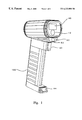
- FIG. 1 is a view illustrating a bar code reader in accordance with the present invention.
- FIG. 2 is a block diagram of a bar code reader in accordance with the present invention.
- FIG. 3 is a flow chart illustrating operation of the bar code reader in accordance with the present invention.
- FIG. 4 a is a three dimensional illustration of the placement of the laser beam and its scan width with respect to the imaging optics and field of view in accordance with the present invention.
- FIG. 4 b illustrates vertical displacement of the laser beam with respect to the imaging optics and field of view in accordance with the present invention.
- FIG. 4 c illustrates vertical and angular displacement of the laser beam with respect to the imaging optics and field of view in accordance with the present invention.
- FIG. 5 illustrates an arrangement of illumination for imaging in accordance with the present invention
- FIG. 6 illustrates an arrangement of a position sensing device for determining range in accordance with the present invention.
- FIGS. 1 and 2 A bar code reader in accordance with the present invention is shown in FIGS. 1 and 2.
- the bar code reader is a combination of a traditional laser scanning reader with a 2D imaging reader.
- the reader can read bar codes with the laser and/or with 2D image capture and processing.
- the 2D imaging reading operation is improved by using the laser scan as a spotter beam for aiming.
- the laser scanner can assist the 2D image processing by providing information on location, type, range, reflectivity, and presence of bar code for 2D reading.
- the reader in accordance with the current invention provides complete backward compatibility with traditional laser scanners along with the 2D imaging capabilities of omnidirectionally reading conventional, damaged, multiple, height modulated, or stacked bar code symbols along with true two dimensional codes (MaxiCode, PDF417, DataMatrix, etc.).
- the majority of the electronic components of the reader are synergistically shared between the laser scanner and the 2D imaging including processor, RAM and ROM memories. Additionally, the processing power required to process the laser scan lines is significantly less than the amount of processing required to process a 2D image.
- a bar code reader with both laser scanning and 2D imaging capabilities provides for a wide range of operating modes.
- the operating mode of the reader is chosen based on factors including the type and quality of bar codes to be read, ambient conditions, and user skill.
- the first mode or “alternating” mode is when the reader alternates between reading with the laser and the 2D imager until the bar code(s) of interest are read. Alternating mode is the preferred default operating mode of the reader, and provides good performance in situations where the reader is used with no a priori knowledge as to what type of bar codes are to be read.
- the third mode is the laser priority mode, where the reader attempts to use the laser scanner at a higher priority than the 2D image scanner.
- This mode would typically be used when the bar codes of interest are usually linear, are physically very long (and would therefore not be completely contained within the field of view of the 2D imager), have very small module sizes, and/or where the bar codes are at very long ranges.
- the fourth mode is 2D priority mode, where the reader attempts to use the 2D imager at a higher priority than the laser scanner.
- This mode would typically be used where the bar codes of interest are typically true two dimensional codes, or damaged, multiple, height modulated, or stacked bar codes symbols. Additionally, this mode is useful when omnidirectional reading of linear codes is desired.
- Another mode is laser only mode, where 2D imaging is never used. This mode is used to conserve power.
- Another mode, 2D only mode is where the laser is never used. The 2D only mode is useful for situations when no laser readable bar codes are expected.
- a bar code reader with a laser scanner and 2D imaging capabilities provides for a wide range of operating modes.
- a 2D imaging module 10 consists of imaging optics 12 coupled to image sensor 14 as shown in FIG. 2 .
- the output of image sensor 14 is converted from analog to digital in A/D converter 16 and stored in memory 18 by processor 30 .
- Memory 18 may be a RAM memory such as SRAM, DRAM, or any other type of read/write memory.
- Illumination is provided by illumination module 80 by LEDs in cluster 82 and cluster 84 under the control of processor 30 .
- the appropriate power for the LEDs is provided by power control 86 responsive to processor 30 .
- Bar code decoding, and overall reader control is provided by processor 30 .
- Laser scanning is provided by laser scan module 40 .
- This module consists of laser 42 , laser power control 41 , collimation optics 44 , scanning mechanism 46 , collection optics 48 , collection sensor 49 , and processing circuitry 50 .
- the output of processing circuitry 50 may also be stored in RAM 18 .
- Trigger 60 activates the reading process.
- the decoded bar code information is output to an external device by I/O port 70 . Additionally, I/O port 70 can be used to supply power to the hand-held reader.
- Processor 30 is typically a high speed microprocessor such as the ARM, PowerPC, Hitachi SH series, MIPS R3000 or R4000, TI320Cx series or the like.
- the memory for processor 30 is both non-volatile memory 19 for storing programs, configuration parameters, etc. (examples include: ROM, flash ROM), and read/write memory 18 for image processing storage/scratch pad.
- the output of reader 100 is decoded bar code information.
- a bar code read operation is triggered in various fashions including manual, automatic, or continuously.
- a bar code read operation is initiated in step 300 in FIG. 3 .
- Processor 30 responds in various fashions depending on the mode of bar code operation desired. Since the bar code reader has the ability to read bar codes with the laser scanner or with 2D image capture and processing, the operational modes are preferably optimized to reduce total read time and to increase overall read rate. The total read time includes the time it takes the operator to correctly position the reader in relationship to the bar code along with the actual time it takes to laser scan or capture an image and process the bar code.
- a bar code read is initiated (step 300 ) by trigger 60 as an input signal to processor 30 .
- Laser scan module 40 is activated at step 310 , producing a laser scan line. This line is used simultaneously by the operator as a spotter beam for aiming the reader, and by the reader to decode any bar code the scan line scans. Reflected light from the laser scan line is collected by collection optics 48 , collection sensor 49 , and processing circuitry 50 (FIG. 2 ). Electrical signal 55 produced by processing circuitry 50 is processed by processor 30 to decode any bar code that is scanned at step 320 .
- Signal 55 may be stored in memory 18 in various ways including direct processor control, using DMA, or by dedicated circuitry.
- the read is complete and scan module 40 is turned off.
- the decoded bar code information is output to an external device by I/O port 70 at step 370 and the system may stop 380 after a successful read.
- Processing circuitry 50 may include waveshaping, thresholding and other circuitry that is well known in the art of laser bar code scanners. Additionally, electrical signal 55 may be digitized to more than one bit, (i.e. gray scale) enabling more sophisticated processing. Most prior art laser scanners threshold received scan lines to binary (i.e. black or white) prior to decoding due to their limited processor capability. However, the current invention already has the processing power required to decode a gray scale 2 dimensional image, enabling sophisticated processing of a one dimensional laser gray scale signal 55 . Additionally, AID converter 16 could be used to digitize signal 55 .
- the laser is shut off, and a 2 dimensional image is captured at step 340 .
- the captured image is read out of image sensor 14 , digitized by A/D converter 16 , and stored in image memory 18 at step 340 .
- the image can be stored memory 18 in various ways including direct processor control, using DMA, or by dedicated circuitry.
- the reader now has a digitized image of its field of view, which may contain a bar code label, stored in image memory 18 .
- Processor 30 executes stored programs to locate and decode the bar code at step 350 . If the decode was successful 360 , the decoded bar code information is output to an external device by I/O port 70 at step 370 and the system may stop at step 380 .
- the laser scanner may detect the presence, type, and location of bar codes, areas of activity, or other information during the processing of signal 55 . If a bar code was not successfully read at step 330 , this information may be used to assist the 2D image processing.
- the processing of the captured image may be interrupted on a regular basis to process new laser scan lines.
- the reader may overlap or time share the processing of laser scan lines with 2D images.
- the amount of time required to process a laser scan line is very small compared to the time required to process a 2D image.
- the operator typically attempts to center the bar code in the field of view of the reader, it is also useful to provide operating modes where the processing of the 2D image concentrates on the center of the image.
- the algorithms can start in the center and work outward to save processing time (assuming the bar code is near centered). Additionally, if there are multiple bar codes in the field of view, the reader can place emphasis on the bar codes closest to the center by issuing them first, suppressing non-centered bar codes, or other variants of operation based on the position of bar codes in the field of view.
- the reader may repeat the entire process as long as the trigger is still activated by returning to step 310 . If a bar code was decoded at step 350 , the reader may then deactivate.
- FIG. 4 a shows field of view 400 of 2D imaging module 10 and laser scan line 410 limited to width W. Additionally, it is preferable to have the width of the laser scan line be adjustable to the approximate horizontal width W of field of view 400 when used for aiming, and to a long width for reading bar codes. This long width is shown by scan segments 410 , 420 , and 430 (for a total width of W+S 1 +S 2 ). Adjustable scan width is accomplished in various ways.
- scanning mechanism 46 includes a resonant structure which is energized by appropriately timed electromagnetic pulses.
- the preferred method of limiting the scan width with a resonant scanner is to cycle the laser on and off using laser power control 41 while scan mechanism 46 remains on continuously.
- the full laser sweep is shown by lines 480 .
- the laser is turned off outside the field of view (segments 420 and 430 ).
- the laser is turned on within the field of view (segment 410 ).
- the correct timing for turning the laser on and off can be determined automatically by capturing and processing images of the laser scan line with the 2D imager. The timing is iteratively adjusted and analyzed until the scan line is the appropriate width. In a preferred method, first, the laser beam is turned off well short of the edge of each side of the field of view. The laser turn on time would be gradually increased (analyzing an image with each increase) until the appropriate width was achieved. These timing parameters would be determined during manufacturing or recalibration and be stored for future use. Additionally, these parameters may be automatically re-calibrated after a predetermined number of reads or period of time has elapsed.
- laser scanners use a scan mechanism comprised of controllable mirrors (driven by galvanometers, stepper motors, etc.).
- the laser can be left on continuously, and the scan width is controlled by adjusting the travel of the scan mirror.
- the scan width parameters (in this case mirror movement) can also be determined using the captured images of the laser scan as described above.
- stop the laser from scanning This can be used as a stationary spotter beam for aiming the reader.
- FIG. 4 b is a side view illustrating the position of laser scan module 40 in relation to imaging module 10 .
- Laser scan module 40 is directly above 2D optical axis 440 and laser beam 450 is horizontally aligned and centered in field of view 400 . A certain amount of parallax is unavoidable since it is impractical to also vertically align and center the laser scan beam.
- laser beam 450 is always slightly above optical axis 440 by a distance V.
- distance V is relatively small, the operator will be able to center bar codes with adequate precision.
- the laser scan line can be aimed slightly downward to place scan beam 450 closer to vertically centered with optical axis 440 as shown in FIG. 4 c .
- the vertical position of scan line 410 in the field of view changes as the range to bar code changes. The vertical position of scan line 410 lowers as the range gets longer.
- the reader can also include a multiple position trigger 60 for separately enabling the laser scanner and the 2D image capture and processing.
- a multiple position trigger 60 for separately enabling the laser scanner and the 2D image capture and processing.
- the reader may operate as follows.
- the laser scan module 40 is activated at step 310 producing a laser scan line limited to the width of field of view 400 .
- the laser scan line is used primarily by the operator as a spotter beam for aiming the reader. However, the scan line is also used to attempt to read bar codes.
- the operator may then pull the trigger to the second position, causing the reader to shut off the laser and capture and process a 2D image. If a decode was successful, the reader outputs the result and turns off. If the decode was unsuccessful and the trigger was still in the second position, the reader may go into any of the modes described above (alternating, known, etc.).
- the reader may also control the laser scan width as a function of trigger position and operating mode. For example, if the trigger is in a first position, the reader may operate in alternating mode with the laser scan width limited to the width of the field of view. If the trigger is pulled and held to a second position, the reader may operate as a traditional laser scanner, with the full laser scan width and no 2D imaging.
- the illumination In order to capture the most accurate image of the label being read, the illumination must be sufficiently uniform over the entire imaged area. There can be slow, gradual variations in illumination intensity over the entire area.
- the absolute level of variation tolerable is a function of the label reflectivity and contrast, and the robustness of the processing algorithms. Sharp, or jagged variations in light intensity over the imaged area are generally not acceptable.
- FIG. 1 and FIG. 5 show an arrangement that can be used to provide uniform illumination at different distances by having multiple clusters of LEDs.
- Each of the clusters are designed to provide uniform light and intensity at varying ranges.
- LED cluster 82 is used at close range, shown as distance Ra.
- the LEDs in cluster 82 should illuminate in a wide angle pattern 510 to cover area 500 a .
- Cluster 84 is used at longer range Rb to illuminate area 500 b .
- the LEDs in cluster 84 should illuminate smaller angle pattern 520 to eliminate wasted light (i.e., light that does not fall within the field of view). At intermediate ranges the illumination will be provided by both clusters.
- LED clusters may be used in combination to provide uniform illumination over all ranges.
- LEDs within a cluster may be pointed in the same way, or be individually aimed to provide the best coverage.
- the type of LED (focal length/angle of radiation, intensity) must be chosen to provide the proper overlaps and uniformity.
- the LEDs can be connected in a fashion that provides tolerance to defective or failed LEDs (example: wired in parallel).
- the LED clusters can be controlled individually or used all together. In the simplest case, all clusters are flashed together. If the reader has the ability to detect range, only the clusters which will provide the best illumination should be used. Additionally, the clusters may have individually controllable output power and duration. Finally, the number and position of clusters, along with the choice of LEDs (angle, power, arrangement) must be chosen to best suit the desired range and coverage width of the reader.
- Specular reflection occurs when an illumination source is reflected in a non-diffuse manner off of a glossy surface onto the imager (i.e. the bar code label acts like a mirror). The result is an overly bright spot which saturates the imager.
- bar code labels with a clear glossy coating bar code labels printed with glossy ink
- bar codes that are behind glossy wrapping such as poly bags, etc.
- bar code readers In normal operation, bar code readers rely on white ( the spaces) reflecting more light than the black (the bars). Any specular reflections reflect more light than either the white or the black, and can render a bar code unreadable unless the specular reflections are eliminated and/or reduced in size.
- cross polarization increases the light energy required by a factor of 6 or more (which dramatically increases electrical energy required, and the number and size of light sources). Additionally, a reader using cross polarization can not take advantage of ambient light for illumination.
- Each cluster of LEDs as shown in FIGS. 1 and 5 act as if they are effectively one point source, giving the reader only 2 effective sources of specular reflections. If a specular reflection is received due to a cluster, only a small portion of the image is therefore rendered unusable.
- the illumination sources are positioned in a way that sends specular reflections off in harmless directions.
- the direction of specular reflection is illustrated by light ray 530 a generated by cluster 84 . If a specularly reflective label is present where this ray intercepts the label at 500 b , the reflected ray 530 b is not seen by the imager, and likewise with light ray 540 a generated by cluster 82 . If a specularly reflective label is present where this ray intercepts the label at 500 a , the reflected ray 540 b is not seen by the imager.
- the reader may include a means to control and power the illumination, shown as LED power module 86 in FIG. 2 .
- the power module is used to provide the energy instantaneously needed by the reader for illumination by using an energy storage device, preferably with low effective series resistance (such as a capacitor), that is charged during the intervals between LED flashes.
- the storage device can be a rechargeable battery (i.e. NiCad).
- Auto focus can be used to greatly increase the usable range of the 2D reader. Additionally, the use of autofocus allows imaging optics with a smaller f number, which allows capturing images using less LED or ambient light and/or using shorter exposure times to reduce motion blur.
- the range from the reader to the label is preferably measured to allow the correct setting of the focus of the imaging optics 12 (FIG. 1 ).
- the reader may determine the distance by using the laser scanner in conjunction with a position sensing device (PSD) such as one made by Hamamatsu shown as 90 in FIG. 1 .
- PSD position sensing device
- Using the laser scanner to determine range combines the functions of laser scanning for bar code reading and range finding for 2D focus setting for 2D reading.
- Position sensing device PSD 90 can also function as laser collection sensor 49 , used to capture the return signal of the laser for bar code reading.
- the use of a band pass optical filter (matched to the laser wave length) may be used to reduce undesired ambient light.
- Laser scan module 40 is positioned in a manner that scans beam 450 horizontally.
- PSD 90 is positioned below the laser in a vertical orientation.
- Lens 95 focuses the reflected laser beam onto PSD 90 .
- the vertical displacement of reflected laser beam 450 on PSD 90 is proportional to the range from the reader to the target. As the range becomes greater, the reflected laser beam moves closer to the top of the PSD 90 . The distance is calculated by simple geometry (similar triangles). If the label is at range Ra, the reflected position of laser beam 450 is at displacement Da. If the label is at the greater range Rb the reflected position of laser beam 450 moves closer to the top of PSD 90 shown as displacement Db.
- the reader can also determine the range by capturing an image of the laser scan on the 2D imager, and then calculating the distance to the bar code by the position of the image of the beam on the image sensor instead of a PSD.
- the laser must be scanned parallel to and offset from the an optical axis of the 2D imaging axis.
- the reader first scans the bar code with the laser used to aim, attempts to read the bar code, and to determine the range. If the laser did not read the bar code, the reader then adjusts the 2D imaging optics based on the determined range, and then captures and processes the image of the bar code. This may be repeated in an iterative fashion until the bar code is read.
- the laser/PSD combination can be used to determine the correct setting for the laser lens (the PSD range finding,described above works even if the laser is not well focused).
- the bar code reader could also prevent images from being captured if the range was not appropriate (i.e. too close or too far). This can apply to a reader with fixed or variable focus optics. Various warnings can also be given to the operator to alert of these conditions including flashing lights, lights of different colors, modulating the laser (dashed pattern, flashing, etc.), or audible warnings.
- the reader can also operate in a mode where the reader auto-triggers when in range.
- the present invention determines the range adding any minimal additional components.
- the reader may be calibrated during manufacture by positioning targets at known distances from the reader.
- the reader can operate in a mode where the reader auto-triggers the image capture when a bar code is present.
- the laser scanner if operated continuously (or repeatedly scans after a predetermined time interval) can detect a bar code's presence by sensing change in the returned signal from a known (or previously captured) background. If the laser scanner detects a change and cannot decode the returned laser signal, an image is then captured and processed.
- Presentation readers are typically hand held scanners that are mounted in a way that allows reading without the operator holding the reader. Presentation readers also include fixed mount readers (i.e. not hand held) such as retail point of sale readers. Presentation readers include any reader where the operator moves the item with a bar code into the field of view of the scanner.
- Any bar code reader including hand held or fixed mount, that comprises both a laser scanning module and a 2D image capture and processing ability are to be considered within the scope of the present invention.
- the exposure can be set based on factors including range, area covered, ambient light, and surface reflectivity.
- the preferred method for controlling the exposure is to control the duration and power of the illumination along with the exposure time of the CCD.
- the method of determining range described above can be used as an input to the correct exposure.
- a suitable image sensor for use with the present invention is a progressive scan CCD such as the Sony KX084.
- a progressive scan imager captures an entire frame in one exposure. It also has an electronic shutter which can stop the charge from integrating at any arbitrary time without the need for a mechanical shutter.
- the sensitivity of these CCDs combined with the level of ambient light available can, in many environments, reduce the need for additional illumination. Additionally, the brighter the ambient conditions, the shorter the exposure time, reducing hand jitter. However, there are still many environments (night, dark warehouses, etc.) that require additional light.
- the reader may “pre-capture” an image of the area likely to contain a bar code without using illumination (or reduced LED illumination) in order to determine the ambient light and label reflectivity. Analysis of the captured image allows the proper setting of illumination duration and CCD exposure time. This pre-capture may occur during the laser scan time, as long as the reader has knowledge of where the reflected scan line can appear on the imager. Alternatively, the laser can be shut off during the “pre-capture” exposure.
- the laser can be used as the illumination source for surface reflectivity determination as well as range determination.
- the light sensor ( 49 or 90 ) and signal processing used to capture the reflected laser scan must have the ability to detect variable levels of light returned.
- Light level sensing is preferably implemented using an A/D converter connected to the light sensor.
- the benefits of using the laser for surface reflectivity determination include lower power consumption since the main illumination sources do not have to be flashed, and a savings in processing and imager readout time, since with one scan of the laser, both the range and the surface reflectivity can be determined simultaneously.
- the 2D CCD can be used to image the area illuminated by the laser scan provided that the CCD exposure and the laser scan occur simultaneously.
- the image read out of the CCD will then contain surface reflectivity levels of the area of the bar code where the laser scanned, along with information about the ambient light levels on the scene were the laser was not scanning.
- the present invention preferably includes a means to minimize power consumption (i.e. quiescent current draw) during the time the reader is not being used. Minimizing quiescent power is achieved by putting the reader in a sleep state and is especially useful for battery powered applications. Additionally, the reader must also be able to “wake-up” from the sleep state as fast as possible in response to a trigger. There are usually tradeoffs in how deep a sleep the reader can be in and how fast it can wake-up versus the power consumption while sleeping.
- power consumption i.e. quiescent current draw
- Factors that contribute to the time it takes the reader to “wake-up” from a quiescent state includes the time for the processor to come out of a sleep state and stabilize, the time for voltages needed for reader to stabilize, the time for the CCD to turn on, and the time to load the program from ROM to RAM. If the program is maintained in RAM (using low current draw self-refreshing DRAMs or SRAM) the time to load the program is eliminated. Additionally, the reader can operate in a manner which enables certain features such as the laser to be energized for aiming while the processor and other circuitry are waking up.
Abstract
Description
Claims (41)
Priority Applications (1)
| Application Number | Priority Date | Filing Date | Title |
|---|---|---|---|
| US09/284,395 US6223988B1 (en) | 1996-10-16 | 1997-10-14 | Hand-held bar code reader with laser scanning and 2D image capture |
Applications Claiming Priority (3)
| Application Number | Priority Date | Filing Date | Title |
|---|---|---|---|
| US2859296P | 1996-10-16 | 1996-10-16 | |
| PCT/US1997/018492 WO1998016896A1 (en) | 1996-10-16 | 1997-10-14 | Hand-held bar code reader with laser scanning and 2d image capture |
| US09/284,395 US6223988B1 (en) | 1996-10-16 | 1997-10-14 | Hand-held bar code reader with laser scanning and 2D image capture |
Publications (1)
| Publication Number | Publication Date |
|---|---|
| US6223988B1 true US6223988B1 (en) | 2001-05-01 |
Family
ID=21844301
Family Applications (1)
| Application Number | Title | Priority Date | Filing Date |
|---|---|---|---|
| US09/284,395 Expired - Lifetime US6223988B1 (en) | 1996-10-16 | 1997-10-14 | Hand-held bar code reader with laser scanning and 2D image capture |
Country Status (2)
| Country | Link |
|---|---|
| US (1) | US6223988B1 (en) |
| WO (1) | WO1998016896A1 (en) |
Cited By (113)
| Publication number | Priority date | Publication date | Assignee | Title |
|---|---|---|---|---|
| US20020030108A1 (en) * | 1991-07-25 | 2002-03-14 | Paul Dvorkis | Two-dimensional optical code scanner with scanning pattern having region of greater apparent brightness for assisting alignment of scanning pattern |
| US20020170970A1 (en) * | 2001-05-15 | 2002-11-21 | Welch Allyn Data Collection, Inc. | Optical reader having decoding and image capturing functionality |
| US20020195496A1 (en) * | 1999-06-07 | 2002-12-26 | Metrologic Instruments, Inc. | Planar LED-based illumination array (PLIA) chips |
| US20030019932A1 (en) * | 1998-03-24 | 2003-01-30 | Tsikos Constantine J. | Method of speckle-noise pattern reduction and apparatus therefor based on reducing the temporal-coherence of the planar laser illumination beam before it illuminates the target object by applying temporal frequency modulation techniques during the transmission of the PLIB towards the target |
| US20030042308A1 (en) * | 1995-12-18 | 2003-03-06 | Tsikos Constantine J. | Pliim-based semiconductor chips |
| US20030042303A1 (en) * | 1999-06-07 | 2003-03-06 | Metrologic Instruments, Inc. | Automatic vehicle identification (AVI) system employing planar laser illumination imaging (PLIIM) based subsystems |
| US20030085284A1 (en) * | 2000-02-28 | 2003-05-08 | Psc Scanning, Inc. | Multi-format bar code reader |
| US20030089779A1 (en) * | 2000-11-24 | 2003-05-15 | Metrologic Instruments, Inc | Planar light illumination and imaging device with modulated coherent illumination that reduces speckle noise induced by coherent illumination |
| US20030091244A1 (en) * | 2000-11-24 | 2003-05-15 | Metrologic Instruments, Inc. | Imaging engine employing planar light illumination and linear imaging |
| US20030125407A1 (en) * | 1998-09-10 | 2003-07-03 | Thomas Bronnum | Co-initiated polyether polyol and process for its preparation |
| US20030174209A1 (en) * | 2002-03-13 | 2003-09-18 | Guglielmo Piazzi | Fixed camera type optical reading equipment and methods for its installation and for the diagnostic of its alignment |
| US6629641B2 (en) | 2000-06-07 | 2003-10-07 | Metrologic Instruments, Inc. | Method of and system for producing images of objects using planar laser illumination beams and image detection arrays |
| US6631842B1 (en) | 2000-06-07 | 2003-10-14 | Metrologic Instruments, Inc. | Method of and system for producing images of objects using planar laser illumination beams and image detection arrays |
| US20030209605A1 (en) * | 2002-03-28 | 2003-11-13 | Joseph Walczyk | Customizable optical reader |
| US20030226895A1 (en) * | 2002-06-11 | 2003-12-11 | Hand Held Products, Inc. | Long range optical reader |
| US20040003024A1 (en) * | 2002-06-26 | 2004-01-01 | Jarkko Sairanen | Method, system and computer program product for personalizing the functionality of a personal communication device |
| US20040004470A1 (en) * | 2002-06-07 | 2004-01-08 | Hitachi, Ltd. | Switching power supply device and switching power supply system |
| US20040010446A1 (en) * | 2002-07-08 | 2004-01-15 | Marko Vanska | Mobile customer relationship management |
| US20040035933A1 (en) * | 2002-06-11 | 2004-02-26 | Havens William H. | Long range optical reader |
| US20040046869A1 (en) * | 2002-09-11 | 2004-03-11 | Dibella James A. | Orientation-sensitive electronic vertical shutter release lock |
| US20040087273A1 (en) * | 2002-10-31 | 2004-05-06 | Nokia Corporation | Method and system for selecting data items for service requests |
| US6732929B2 (en) | 1990-09-10 | 2004-05-11 | Metrologic Instruments, Inc. | Led-based planar light illumination beam generation module employing a focal lens for reducing the image size of the light emmiting surface of the led prior to beam collimation and planarization |
| US20040093274A1 (en) * | 2002-11-08 | 2004-05-13 | Marko Vanska | Method and apparatus for making daily shopping easier |
| US20040118928A1 (en) * | 2002-12-18 | 2004-06-24 | Mehul Patel | System and method for imaging and decoding optical codes using at least two different imaging settings |
| US20040129783A1 (en) * | 2003-01-03 | 2004-07-08 | Mehul Patel | Optical code reading device having more than one imaging engine |
| US20040134989A1 (en) * | 2003-01-09 | 2004-07-15 | Hand Held Products, Inc. | Decoder board for an optical reader utilizing a plurality of imaging formats |
| US20040155109A1 (en) * | 2003-02-12 | 2004-08-12 | Sears Brands, Llc | Digital assistant for use in a commercial environment |
| US20040164165A1 (en) * | 2002-06-04 | 2004-08-26 | Havens William H. | Optical reader having a plurality of imaging modules |
| US20040195328A1 (en) * | 1999-10-04 | 2004-10-07 | Welch Allyn Data Collection Inc. | Imaging module for optical reader |
| US20050023352A1 (en) * | 2003-08-01 | 2005-02-03 | Mehul Patel | Imaging and illumination engine for an optical code reader |
| US20050072845A1 (en) * | 2003-10-02 | 2005-04-07 | Maiman Mitchell H. | Image capture device for and method of electro-optically reading indicia at low ambient light levels |
| US20050098631A1 (en) * | 1995-12-18 | 2005-05-12 | Dorris R. M. | Holographic laser scanning method and system employing visible scanning-zone indicators identifying a three-dimensional omni-directional laser scanning volume for package transport navigation |
| US20050103867A1 (en) * | 2003-11-13 | 2005-05-19 | Xiaoxun Zhu | Hand-supportable semi-automatic digital imaging-based bar code symbol reading system realized upon a multi-tier modular software platform |
| US20050125745A1 (en) * | 2003-12-08 | 2005-06-09 | Jyri Engestrom | Apparatus, system, method and computer program product for creating shortcuts to functions in a personal communication device |
| US20050167504A1 (en) * | 1997-10-17 | 2005-08-04 | Meier Timothy P. | Bar code reading device having image processing mode |
| US20050222918A1 (en) * | 2002-11-01 | 2005-10-06 | Marko Vanska | Disposable mini-applications |
| US20050263599A1 (en) * | 2003-11-13 | 2005-12-01 | Metrologic Instruments, Inc. | Digital imaging-based bar code symbol reading system employing a multi-mode image-processing symbol reading subsystem that switches its modes of reading during a single bar code symbol reading cycle, and within each said mode of reading, automatically applies a different image-processing based bar code symbol reading methodology |
| US20060002610A1 (en) * | 2004-07-02 | 2006-01-05 | Hartti Suomela | Initiation of actions with compressed action language representations |
| US6988660B2 (en) | 1999-06-07 | 2006-01-24 | Metrologic Instruments, Inc. | Planar laser illumination and imaging (PLIIM) based camera system for producing high-resolution 3-D images of moving 3-D objects |
| US20060027659A1 (en) * | 2003-08-01 | 2006-02-09 | Symbol Technologies, Inc. | Integrated exit window and imaging engine |
| US20060043194A1 (en) * | 2004-08-31 | 2006-03-02 | Edward Barkan | Scanner and method for eliminating specular reflection |
| US20060097053A1 (en) * | 2004-06-25 | 2006-05-11 | Denis Jolivet | Reader for reading machine-readable symbols, for example bar code symbols |
| US20060098433A1 (en) * | 2000-03-17 | 2006-05-11 | Accu-Sort Systems, Inc. | Coplanar camera scanning system |
| US20060151608A1 (en) * | 2005-01-10 | 2006-07-13 | Symagery Microsystems Inc. | Targeting system for a portable image reader |
| WO2006078359A1 (en) * | 2004-12-03 | 2006-07-27 | Symbol Technologies, Inc. | Bar code scanner decoding |
| US20060202036A1 (en) * | 2005-03-11 | 2006-09-14 | Ynjiun Wang | Bar code reading device with global electronic shutter control |
| US20060202038A1 (en) * | 2005-03-11 | 2006-09-14 | Ynjiun Wang | System and method to automatically focus an image reader |
| US20060208086A1 (en) * | 2005-03-15 | 2006-09-21 | Psc Scanning, Inc. | Multifunction trigger for RFID and optical readers |
| US20060219792A1 (en) * | 2003-11-13 | 2006-10-05 | Metrologic Instruments, Inc. | Hand-supportable digital imaging-based bar code symbol reader employing an event-driven system control subsystem, automatic IR-based object detection, and trigger-switch activated image capture and processing subsystem |
| US20060274171A1 (en) * | 2005-06-03 | 2006-12-07 | Ynjiun Wang | Digital picture taking optical reader having hybrid monochrome and color image sensor array |
| US20070040035A1 (en) * | 2003-11-13 | 2007-02-22 | Metrologic Instruments, Inc. | Method of and apparatus for dynamically and adaptively controlling system control parameters in a multi-mode image capture and processing system |
| US20070084926A1 (en) * | 2005-08-18 | 2007-04-19 | Intermec Ip Corp. | Functional aiming system for an automatic data collection device, such as an image acquisition device |
| US20070108283A1 (en) * | 2005-11-16 | 2007-05-17 | Serge Thuries | Sensor control of an aiming beam of an automatic data collection device, such as a barcode reader |
| US20070138284A1 (en) * | 2001-11-21 | 2007-06-21 | Metrologic Instruments, Inc. | Planar light illumination and imaging device with modulated coherent illumination that reduces speckle noise induced by coherent illumination |
| US20070164112A1 (en) * | 2006-01-04 | 2007-07-19 | Intermec Ip Corp. | Method and system for facilitating aiming of a machine-readable symbol reader, such as barcode reader |
| US20070170259A1 (en) * | 2006-01-25 | 2007-07-26 | Laurens Nunnink | Method and apparatus for providing a focus indication for optical imaging of visual codes |
| US20070210170A1 (en) * | 2000-11-24 | 2007-09-13 | Metrologic Instruments, Inc. | Digital-imaging based code symbol reading system employing a plurality of coplanar illumination and imaging subsystems, global object motion detection subsystem for automatic detecting objects within its 3D imaging volume, and global control subsystem for managing the state of operation of said coplanar illumination and imaging subsystems |
| US7337970B2 (en) | 2004-12-03 | 2008-03-04 | Symbol Technologies, Inc. | Barcode scanner decoding |
| US20080128506A1 (en) * | 1998-03-24 | 2008-06-05 | Tsikos Constantine J | Hand-supportable planar laser illumination and imaging (PLIIM) based systems with laser despeckling mechanisms integrated therein |
| US7392951B2 (en) | 2005-05-17 | 2008-07-01 | Intermec Ip Corp. | Methods, apparatuses and articles for automatic data collection devices, for example barcode readers, in cluttered environments |
| US7395971B2 (en) | 2000-11-24 | 2008-07-08 | Metrologic Instruments, Inc. | Method of and system for profile equalization employing visible laser diode (VLD) displacement |
| US20080252985A1 (en) * | 2000-11-24 | 2008-10-16 | Metrologic Instruments, Inc. | Tunnel-type digital imaging-based self-checkout system for use in retail point-of-sale environments |
| US20080292137A1 (en) * | 1999-05-19 | 2008-11-27 | Rhoads Geoffrey B | Methods and Systems for Interacting with Physical Objects |
| US20090026267A1 (en) * | 2007-06-04 | 2009-01-29 | Hand Held Products, Inc. | Indicia reading terminal processing plurality of frames of image data responsively to trigger signal activation |
| US20090039166A1 (en) * | 2007-08-08 | 2009-02-12 | Ncr Corporation | Methods and Apparatus for Positioning Objects for Scanning By a Hybrid Laser and Imaging Scanner |
| EP2073145A1 (en) * | 2007-12-20 | 2009-06-24 | NCR Corporation | A method, device and system for a laser bar code scanner with imaging assist |
| US20090166438A1 (en) * | 2007-12-31 | 2009-07-02 | Pitney Bowes Inc. | Systems and methods for producing and processing time dependent dynamic barcodes in a mail delivery system |
| US20090166401A1 (en) * | 2007-12-31 | 2009-07-02 | Pitney Bowes Inc. | Time limited business reply mail |
| US20090236424A1 (en) * | 1999-10-04 | 2009-09-24 | Hand Held Products, Inc. | Image sensor based optical reader |
| WO2009120533A2 (en) * | 2008-03-26 | 2009-10-01 | Symbol Technologies, Inc. | Method and system for limiting peak power consumption in an imaging bar code scanner |
| US20090272804A1 (en) * | 2008-05-02 | 2009-11-05 | Symbol Technologies, Inc. | Method and apparatus for reading optical indicia |
| US20090294541A1 (en) * | 2007-12-21 | 2009-12-03 | Laurens Nunnink | Handheld Code Reader Having A Motion Sensor |
| US20090321525A1 (en) * | 2008-06-30 | 2009-12-31 | Edward Barkan | Data capture terminal with multiple readers operable in handheld and hands-free modes of operation |
| US20100001072A1 (en) * | 2004-10-27 | 2010-01-07 | Denso Corporation | Camera operating system and matrix code decoding device |
| US20100001855A1 (en) * | 2008-07-02 | 2010-01-07 | Essence Security International Ltd. (E.S.I) | Energy-conserving triggered id system and method |
| US7661597B2 (en) | 2000-11-24 | 2010-02-16 | Metrologic Instruments, Inc. | Coplanar laser illumination and imaging subsystem employing spectral-mixing and despeckling of laser illumination |
| US7686222B2 (en) | 2001-07-13 | 2010-03-30 | Hand Held Products, Inc. | Optical reader having a color imager |
| WO2010045192A1 (en) * | 2008-10-16 | 2010-04-22 | Symbol Technologies, Inc. | Hybrid laser scanning and imaging reader |
| US7708205B2 (en) | 2003-11-13 | 2010-05-04 | Metrologic Instruments, Inc. | Digital image capture and processing system employing multi-layer software-based system architecture permitting modification and/or extension of system features and functions by way of third party code plug-ins |
| US20100127081A1 (en) * | 2008-11-25 | 2010-05-27 | Metrologic Instruments, Inc. | Targeting scheme for dataform readers |
| US20100133345A1 (en) * | 2008-12-02 | 2010-06-03 | Hand Held Products, Inc. | Indicia reading terminal having plurality of optical assemblies |
| US20100140356A1 (en) * | 2003-05-12 | 2010-06-10 | Hand Held Products, Inc. | Apparatus comprising image sensor |
| US20100147957A1 (en) * | 2008-12-17 | 2010-06-17 | Vladimir Gurevich | Range finding in imaging reader for electro-optically reading indicia |
| US7748620B2 (en) | 2002-01-11 | 2010-07-06 | Hand Held Products, Inc. | Transaction terminal including imaging module |
| US20100176319A1 (en) * | 2009-01-12 | 2010-07-15 | Cognex Corporation | Modular focus system for image based code readers (as amended) |
| US7770799B2 (en) | 2005-06-03 | 2010-08-10 | Hand Held Products, Inc. | Optical reader having reduced specular reflection read failures |
| US7841533B2 (en) | 2003-11-13 | 2010-11-30 | Metrologic Instruments, Inc. | Method of capturing and processing digital images of an object within the field of view (FOV) of a hand-supportable digitial image capture and processing system |
| US7922088B2 (en) | 2004-10-05 | 2011-04-12 | Hand Held Products, Inc. | System and method to automatically discriminate between different data types |
| US8038538B2 (en) | 2004-06-04 | 2011-10-18 | Mattel, Inc. | Electronic device for enhancing an interactive experience with a tangible medium of expression |
| US20120153022A1 (en) * | 2002-06-04 | 2012-06-21 | Hand Held Products, Inc. | Apparatus operative for capture of image data |
| US8302864B2 (en) | 2007-12-28 | 2012-11-06 | Cognex Corporation | Method and apparatus using aiming pattern for machine vision training |
| US8397992B2 (en) | 1994-03-04 | 2013-03-19 | Hand Held Products, Inc. | Optical reader having image sensor for reading decodable indicia |
| US8439262B2 (en) | 2001-05-15 | 2013-05-14 | Hand Held Products, Inc. | Image capture apparatus and method |
| US8459557B2 (en) | 2011-03-10 | 2013-06-11 | Metrologic Instruments, Inc. | Dual laser scanning code symbol reading system employing automatic object presence detector for automatic laser source selection |
| US8561903B2 (en) | 2011-01-31 | 2013-10-22 | Hand Held Products, Inc. | System operative to adaptively select an image sensor for decodable indicia reading |
| US8608071B2 (en) | 2011-10-17 | 2013-12-17 | Honeywell Scanning And Mobility | Optical indicia reading terminal with two image sensors |
| US8622299B2 (en) * | 2011-11-30 | 2014-01-07 | Ncr Corporation | Apparatus, method and system for determining the source of an optical code presentated to an optical code scanner |
| US8629926B2 (en) | 2011-11-04 | 2014-01-14 | Honeywell International, Inc. | Imaging apparatus comprising image sensor array having shared global shutter circuitry |
| US8646689B2 (en) | 2007-12-28 | 2014-02-11 | Cognex Corporation | Deformable light pattern for machine vision system |
| US8657200B2 (en) | 2011-06-20 | 2014-02-25 | Metrologic Instruments, Inc. | Indicia reading terminal with color frame processing |
| USD734753S1 (en) * | 2014-04-17 | 2015-07-21 | Faro Technologies, Inc. | Laser scanning device |
| US9746636B2 (en) | 2012-10-19 | 2017-08-29 | Cognex Corporation | Carrier frame and circuit board for an electronic device |
| US9940497B2 (en) * | 2016-08-16 | 2018-04-10 | Hand Held Products, Inc. | Minimizing laser persistence on two-dimensional image sensors |
| CN107898174A (en) * | 2017-11-26 | 2018-04-13 | 国家电网公司 | Quick Response Code information filing device |
| USD822841S1 (en) * | 2016-06-29 | 2018-07-10 | HUNTKEY JAPAN Inc. | Thermal therapeutic apparatus |
| US10067312B2 (en) | 2011-11-22 | 2018-09-04 | Cognex Corporation | Vision system camera with mount for multiple lens types |
| US10127422B1 (en) | 2007-12-21 | 2018-11-13 | Cognex Corporation | Handheld code reader having a motion sensor |
| USD848429S1 (en) * | 2017-11-08 | 2019-05-14 | Lee Seng Fook | Hand held 3D scanning device with feedback system |
| USD848428S1 (en) * | 2017-11-08 | 2019-05-14 | Lee Seng Fook | Hand held 3D scanning device |
| USD861692S1 (en) * | 2016-08-01 | 2019-10-01 | Hand Held Products, Inc. | Optical scanner |
| US10498933B2 (en) | 2011-11-22 | 2019-12-03 | Cognex Corporation | Camera system with exchangeable illumination assembly |
| KR102258277B1 (en) | 2020-10-27 | 2021-05-31 | 주식회사 리얼타임메디체크 | Vaccine management device and vaccine management system including the same |
| US11366284B2 (en) | 2011-11-22 | 2022-06-21 | Cognex Corporation | Vision system camera with mount for multiple lens types and lens module for the same |
Families Citing this family (7)
| Publication number | Priority date | Publication date | Assignee | Title |
|---|---|---|---|---|
| US5979768A (en) * | 1988-01-14 | 1999-11-09 | Intermec I.P. Corp. | Enhanced bar code resolution through relative movement of sensor and object |
| US6688523B1 (en) | 1988-08-31 | 2004-02-10 | Intermec Ip Corp. | System for reading optical indicia |
| US6686910B2 (en) * | 1996-04-22 | 2004-02-03 | O'donnell, Jr. Francis E. | Combined writing instrument and digital documentor apparatus and method of use |
| EP1715439A3 (en) | 1998-11-02 | 2007-10-10 | Datalogic S.P.A. | Device for the acquisition and automatic processing of data obtained from optical codes |
| FR2788871B1 (en) * | 1999-01-22 | 2001-06-15 | Intermec Scanner Technology Ct | OPTOELECTRONIC DEVICE FOR ACQUIRING IMAGES OF CODES WITH ONE AND TWO DIMENSIONS |
| FR2803067A1 (en) | 1999-12-23 | 2001-06-29 | Intermec Scanner Technology Ct | OPTOELECTRONIC DEVICE AND METHOD FOR ACQUIRING CODES USING AN OPTIMIZED TWO-DIMENSIONAL USEFUL SENSOR |
| DE60041580D1 (en) * | 2000-07-11 | 2009-04-02 | Datalogic Spa | Device and optical element for viewing and visual display of a read-out area of a code reader |
Citations (4)
| Publication number | Priority date | Publication date | Assignee | Title |
|---|---|---|---|---|
| US5378883A (en) * | 1991-07-19 | 1995-01-03 | Omniplanar Inc. | Omnidirectional wide range hand held bar code reader |
| US5621203A (en) * | 1992-09-25 | 1997-04-15 | Symbol Technologies | Method and apparatus for reading two-dimensional bar code symbols with an elongated laser line |
| US5672858A (en) * | 1994-06-30 | 1997-09-30 | Symbol Technologies Inc. | Apparatus and method for reading indicia using charge coupled device and scanning laser beam technology |
| US5710417A (en) * | 1988-10-21 | 1998-01-20 | Symbol Technologies, Inc. | Bar code reader for reading both one dimensional and two dimensional symbologies with programmable resolution |
-
1997
- 1997-10-14 US US09/284,395 patent/US6223988B1/en not_active Expired - Lifetime
- 1997-10-14 WO PCT/US1997/018492 patent/WO1998016896A1/en active Application Filing
Patent Citations (4)
| Publication number | Priority date | Publication date | Assignee | Title |
|---|---|---|---|---|
| US5710417A (en) * | 1988-10-21 | 1998-01-20 | Symbol Technologies, Inc. | Bar code reader for reading both one dimensional and two dimensional symbologies with programmable resolution |
| US5378883A (en) * | 1991-07-19 | 1995-01-03 | Omniplanar Inc. | Omnidirectional wide range hand held bar code reader |
| US5621203A (en) * | 1992-09-25 | 1997-04-15 | Symbol Technologies | Method and apparatus for reading two-dimensional bar code symbols with an elongated laser line |
| US5672858A (en) * | 1994-06-30 | 1997-09-30 | Symbol Technologies Inc. | Apparatus and method for reading indicia using charge coupled device and scanning laser beam technology |
Cited By (461)
| Publication number | Priority date | Publication date | Assignee | Title |
|---|---|---|---|---|
| US6732929B2 (en) | 1990-09-10 | 2004-05-11 | Metrologic Instruments, Inc. | Led-based planar light illumination beam generation module employing a focal lens for reducing the image size of the light emmiting surface of the led prior to beam collimation and planarization |
| US6948662B2 (en) * | 1991-07-25 | 2005-09-27 | Symbol Technologies, Inc. | Two-dimensional optical code scanner with scanning pattern having region of greater apparent brightness for assisting alignment of scanning pattern |
| US20020030108A1 (en) * | 1991-07-25 | 2002-03-14 | Paul Dvorkis | Two-dimensional optical code scanner with scanning pattern having region of greater apparent brightness for assisting alignment of scanning pattern |
| US8602309B2 (en) | 1994-03-04 | 2013-12-10 | Hand Held Products, Inc. | Bar code reading device for reading 1D or 2D bar code symbols |
| US8397992B2 (en) | 1994-03-04 | 2013-03-19 | Hand Held Products, Inc. | Optical reader having image sensor for reading decodable indicia |
| US20030042308A1 (en) * | 1995-12-18 | 2003-03-06 | Tsikos Constantine J. | Pliim-based semiconductor chips |
| US7055745B2 (en) | 1995-12-18 | 2006-06-06 | Metrologic Instruments, Inc. | Laser scanning method and system employing visible scanning-zone indicators identifying a three-dimensional omni-directional laser scanning volume for package transport |
| US20050098631A1 (en) * | 1995-12-18 | 2005-05-12 | Dorris R. M. | Holographic laser scanning method and system employing visible scanning-zone indicators identifying a three-dimensional omni-directional laser scanning volume for package transport navigation |
| US6736321B2 (en) | 1995-12-18 | 2004-05-18 | Metrologic Instruments, Inc. | Planar laser illumination and imaging (PLIIM) system employing wavefront control methods for reducing the power of speckle-pattern noise digital images acquired by said system |
| US6971578B2 (en) | 1995-12-18 | 2005-12-06 | Metrologic Instruments, Inc. | Planar laser illumination and imaging module (PLIIN) based semiconductor chips |
| US20090200380A1 (en) * | 1997-10-17 | 2009-08-13 | Hand Held Products, Inc. | Bar code reading device having image processing mode |
| US20050167504A1 (en) * | 1997-10-17 | 2005-08-04 | Meier Timothy P. | Bar code reading device having image processing mode |
| US8282006B2 (en) | 1997-10-17 | 2012-10-09 | Hand Held Products, Inc. | Imaging device operative for image processing |
| US7841532B2 (en) | 1997-10-17 | 2010-11-30 | Hand Held Products, Inc. | Bar code reading device having image processing mode |
| US7832643B2 (en) | 1998-03-24 | 2010-11-16 | Metrologic Instruments, Inc. | Hand-supported planar laser illumination and imaging (PLIIM) based systems with laser despeckling mechanisms integrated therein |
| US7673803B2 (en) | 1998-03-24 | 2010-03-09 | Metrologic Instruments, Inc. | Planar laser illumination and imaging (PLIIM) based engine |
| US20080128508A1 (en) * | 1998-03-24 | 2008-06-05 | Tsikos Constantine J | Tunnel-type digital imaging system for use within retail shopping environments such as supermarkets |
| US20030062414A1 (en) * | 1998-03-24 | 2003-04-03 | Metrologic Instruments, Inc. | Method of and apparatus for automatically cropping captured linear images of a moving object prior to image processing using region of interest (ROI) coordinate specifications captured by an object profiling subsystem |
| US6863216B2 (en) | 1998-03-24 | 2005-03-08 | Constantine J. Tsikos | Method of speckle-noise pattern reduction and apparatus therefor based on reducing the spatial-coherence of the planar laser illumination beam before it illuminates the target object by applying spatial phase modulation techniques during the transmission of the plib towards the target |
| US6857570B2 (en) | 1998-03-24 | 2005-02-22 | Metrologic Instruments, Inc. | Method of speckle-noise pattern reduction and apparatus therefor based on reducing the temporal-coherence of the planar laser illumination beam before it illuminates the target object by applying temporal frequency modulation techniques during the transmission of the plib towards the target |
| US20070012777A1 (en) * | 1998-03-24 | 2007-01-18 | Tsikos Constantine J | Planar laser illumination and imaging (PLIIM) systems with integrated despeckling mechanisms provided therein |
| US6837432B2 (en) | 1998-03-24 | 2005-01-04 | Metrologic Instruments, Inc. | Method of and apparatus for automatically cropping captured linear images of a moving object prior to image processing using region of interest (roi) coordinate specifications captured by an object profiling subsystem |
| US6827265B2 (en) | 1998-03-24 | 2004-12-07 | Metrologic Instruments, Inc. | Automatic vehicle identification and classification (AVIC) system employing a tunnel-arrangement of PLIIM-based subsystems |
| US6880756B2 (en) | 1998-03-24 | 2005-04-19 | Metrologic Instruments, Inc. | Method of speckle-noise pattern reduction and apparatus therefor based on reducing the temporal-coherence of the planar laser illumination beam (plib) after it illuminates the target by applying temporal intensity modulation techniques during the detection of the reflected/scattered plib |
| US20080128506A1 (en) * | 1998-03-24 | 2008-06-05 | Tsikos Constantine J | Hand-supportable planar laser illumination and imaging (PLIIM) based systems with laser despeckling mechanisms integrated therein |
| US20080135621A1 (en) * | 1998-03-24 | 2008-06-12 | Tsikos Constantine J | Hand-supportable planar laser illumination and imaging (PLIIM) based systems with laser despeckling mechanisms integrated therein |
| US6923374B2 (en) | 1998-03-24 | 2005-08-02 | Metrologic Instruments, Inc. | Neutron-beam based scanning system having an automatic object identification and attribute information acquisition and linking mechanism integrated therein |
| US20030019932A1 (en) * | 1998-03-24 | 2003-01-30 | Tsikos Constantine J. | Method of speckle-noise pattern reduction and apparatus therefor based on reducing the temporal-coherence of the planar laser illumination beam before it illuminates the target object by applying temporal frequency modulation techniques during the transmission of the PLIB towards the target |
| US20030034396A1 (en) * | 1998-03-24 | 2003-02-20 | Tsikos Constantine J. | Method of speckle-noise pattern reduction and apparatus therefor based on reducing the spatial-coherence of the planar laser illumination beam before it illuminates the target object by applying spatial phase modulation techniques during the transmission of the PLIB towards the target |
| US6971577B2 (en) | 1998-03-24 | 2005-12-06 | Metrologic Instruments, Inc. | Method of and system for automatically producing digital images of a moving object, with pixels having a substantially uniform white level independent of the velocity of said moving object |
| US20080128507A1 (en) * | 1998-03-24 | 2008-06-05 | Tsikos Constantine J | Tunnel-type digital imaging system for use within retail shopping environments such as supermarkets |
| US20030125407A1 (en) * | 1998-09-10 | 2003-07-03 | Thomas Bronnum | Co-initiated polyether polyol and process for its preparation |
| US20080292137A1 (en) * | 1999-05-19 | 2008-11-27 | Rhoads Geoffrey B | Methods and Systems for Interacting with Physical Objects |
| US7628320B2 (en) | 1999-05-19 | 2009-12-08 | Digimarc Corporation | Methods and systems for interacting with physical objects |
| US6830184B2 (en) | 1999-06-07 | 2004-12-14 | Metrologic Instruments, Inc. | Method of and apparatus for automatically compensating for viewing-angle distortion in digital linear images of object surfaces moving past a planar laser illumination and imaging (pliim) based camera system at skewed viewing angles |
| US7059524B2 (en) | 1999-06-07 | 2006-06-13 | Metrologic Instruments, Inc. | Nuclear resonance based scanning system having an automatic object identification and attribute information acquisition and linking mechanism integrated therein |
| US20030218070A1 (en) * | 1999-06-07 | 2003-11-27 | Metrologic Instruments, Inc. | Hand-supportable planar laser illumination and imaging (PLIIM) based camera system capable of producing digital linear images of a object, containing pixels having a substantially uniform aspectratio independent of the measured relative velocity of said object while manually moving said PLIIM based camera system past said object during illumination and imaging operations |
| US7303132B2 (en) | 1999-06-07 | 2007-12-04 | Meterologic Instruments, Inc. | X-radiation scanning system having an automatic object identification and attribute information acquisition and linking mechanism integrated therein |
| US6997386B2 (en) | 1999-06-07 | 2006-02-14 | Metrologic Instruments, Inc. | Planar laser illumination and imaging (pliim) device employing a linear image detection array having vertically-elongated image detection elements, wherein the height of the vertically-elongated image detection elements and the f/# parameter of the image formation optics are configured to reduce speckle-pattern noise power through spatial-averaging of detected speckle-noise patterns |
| US20030189098A1 (en) * | 1999-06-07 | 2003-10-09 | Metrologic Instruments, Inc. | Planar light illumination and imaging (PLIIM) systems employing LED-based planar light illumination arrays (PLIAS) and linear electronic image detection arrays |
| US20060086794A1 (en) * | 1999-06-07 | 2006-04-27 | Metrologic Instruments, Inc.. | X-radiation scanning system having an automatic object identification and attribute information acquisition and linking mechanism integrated therein |
| US20080156882A1 (en) * | 1999-06-07 | 2008-07-03 | Metrologic Instruments, Inc. | Methods of and systems for producing digital images of objects with subtantially reduces speckle-noise power by illuminating said objects with wavefront-controlled planar laser illumination beams |
| US6991166B2 (en) | 1999-06-07 | 2006-01-31 | Metrologic Instruments, Inc. | LED-based planar light illumination and imaging (PLIIM) engine |
| US6991165B2 (en) | 1999-06-07 | 2006-01-31 | Metrologic Instruments, Inc. | Method of speckle-noise pattern reduction and apparatus therefor based on reducing the temporal coherence of the planar laser illumination beam before it illuminates the target object by applying temporal intensity modulation techniques during the transmission of the plib towards the target |
| US6988660B2 (en) | 1999-06-07 | 2006-01-24 | Metrologic Instruments, Inc. | Planar laser illumination and imaging (PLIIM) based camera system for producing high-resolution 3-D images of moving 3-D objects |
| US20030150916A1 (en) * | 1999-06-07 | 2003-08-14 | Metrologic Instruments, Inc. | LED-based planar light illumination and imaging (PLIIM) systems |
| US20030146282A1 (en) * | 1999-06-07 | 2003-08-07 | Metrologic Instruments, Inc. | Bioptical product and produce identification systems employing planar laser illumination and imaging (PLIM) based subsystems |
| US20030102379A1 (en) * | 1999-06-07 | 2003-06-05 | Metrologic Instruments Inc. | LED-based planar light illumination and imaging (PLIIM) engine |
| US20080116279A1 (en) * | 1999-06-07 | 2008-05-22 | Metrologic Instruments,Inc. | Hand-supportable code symbol reader employing coplanar laser illumination and linear imaging |
| US6739511B2 (en) | 1999-06-07 | 2004-05-25 | Metrologic Instruments, Inc. | Method of speckle-noise pattern reduction and apparatus therefor based on reducing the temporal-coherence of the planar laser illumination beam before it illuminates the target object by applying temporal phase modulation techniques during the transmission of the plib towards the target |
| US6978936B2 (en) | 1999-06-07 | 2005-12-27 | Metpologic Instruments, Inc. | Method of and system for automatically producing digital images of moving objects, with pixels having a substantially uniform white level independent of the velocities of the moving objects |
| US6742711B2 (en) | 1999-06-07 | 2004-06-01 | Metrologic Instruments, Inc. | Method of extending the working distance of a planar laser illumination and imaging system without increasing the output power of the visible laser diode (VLD) sources employed there |
| US6978935B2 (en) | 1999-06-07 | 2005-12-27 | Metrologic Instruments, Inc. | Planar light illumination and imaging (pliim) based system having a linear image detection chip mounting assembly with means for preventing misalignment between the field of view (fov) of said linear image detection chip and the co-planar laser illumination beam (plib) produced by said pliim based system, in response to thermal expansion and/or contraction within said pliim based system |
| US7644866B2 (en) | 1999-06-07 | 2010-01-12 | Metrologic Instruments, Inc. | Hand-supportable code symbol reader employing coplanar laser illumination and linear imaging |
| US20020195496A1 (en) * | 1999-06-07 | 2002-12-26 | Metrologic Instruments, Inc. | Planar LED-based illumination array (PLIA) chips |
| US6764008B2 (en) | 1999-06-07 | 2004-07-20 | Metrologic Instruments, Inc. | Planar laser illumination and imaging (PLIIM) system employing an area-type image detection array |
| US6971576B2 (en) | 1999-06-07 | 2005-12-06 | Metrologic Instruments, Inc. | Generalized method of speckle-noise pattern reduction and particular forms of apparatus therefor based on reducing the spatial-coherence of the planar laser illumination beam after it illuminates the target by applying spatial intensity modulation techniques during the detection of the reflected/scattered plib |
| US20030085281A1 (en) * | 1999-06-07 | 2003-05-08 | Knowles C. Harry | Tunnel-type package identification system having a remote image keying station with an ethernet-over-fiber-optic data communication link |
| US6786414B2 (en) | 1999-06-07 | 2004-09-07 | Metrologic Instruments, Inc. | Planar laser illumination and imaging (PLIIM) systems |
| US20030024987A1 (en) * | 1999-06-07 | 2003-02-06 | Metrologic Instruments, Inc. | Method of and apparatus for producing a digital image of an object with reduced speckle-pattern noise, by consecutively capturing, buffering and processing a series of digital images of the object over a series of consecutively different photo-integration time periods |
| US6971575B2 (en) | 1999-06-07 | 2005-12-06 | Metrologic Instruments, Inc. | Hand-supportable planar laser illumination and imaging (pliim) device employing a pair of linear laser diode arrays mounted about an area image detection array, for illuminating an object to be imaged with a plurality of optically-combined spatially-incoherent planar laser illumination beams (plibs) scanned through the field of view (fov) of said area image detection array, and reducing the speckle-pattern noise power in detected 2-d images by temporally-averaging detected speckle-noise patterns |
| US7028899B2 (en) | 1999-06-07 | 2006-04-18 | Metrologic Instruments, Inc. | Method of speckle-noise pattern reduction and apparatus therefore based on reducing the temporal-coherence of the planar laser illumination beam before it illuminates the target object by applying temporal phase modulation techniques during the transmission of the plib towards the target |
| US6830185B2 (en) | 1999-06-07 | 2004-12-14 | Metrologic Instruments, Inc. | Method of and system for automatically producing digital images of a moving object, with pixels having a substantially uniform white level independent of the velocity of said moving object |
| US20030085280A1 (en) * | 1999-06-07 | 2003-05-08 | Metrologic Instruments, Inc. | Method of speckle-noise pattern reduction and apparatus therefor based on reducing the spatial-coherence of the planar laser illumination beam before it illuminates the target object by applying spatial intensity modulation techniques during the transmission of the PLIB towards the target |
| US6837437B2 (en) | 1999-06-07 | 2005-01-04 | Metrologic Instruments, Inc. | Planar laser illumination modules (PLIMS) employed in a planar laser illumination and imaging (PLIIM) system |
| US6969001B2 (en) | 1999-06-07 | 2005-11-29 | Metrologic Instruments, Inc. | Method of speckle-noise pattern reduction and apparatus therefor based on reducing the spatial-coherence of the planar laser illumination beam before it illuminates the target object by applying spatial intensity modulation techniques during the transmission of the plib towards the target |
| US20030080190A1 (en) * | 1999-06-07 | 2003-05-01 | Tsikos Constantine J. | Method of and system for automatically producing digital images of a moving object, with pixels having a substantially uniform white level independent of the velocity of said moving object |
| US6962289B2 (en) | 1999-06-07 | 2005-11-08 | Metrologic Instruments, Inc. | Method of and system for producing high-resolution 3-D images of 3-D object surfaces having arbitrary surface geometry |
| US6851610B2 (en) | 1999-06-07 | 2005-02-08 | Metrologic Instruments, Inc. | Tunnel-type package identification system having a remote image keying station with an ethernet-over-fiber-optic data communication link |
| US20030071128A1 (en) * | 1999-06-07 | 2003-04-17 | Metrologic Instruments, Inc. | Led-based planar light illumination and imaging (PLIIM) based camera system employing real-time object coordinate acquistion and producing to control automatic zoom and focus imaging optics |
| US20030071123A1 (en) * | 1999-06-07 | 2003-04-17 | Metrologic Instruments, Inc. | Method of speckle-noise pattern reduction and apparatus therefor based on reducing the temporal coherence of the planar laser illumination beam before it illuminates the target object by applying temporal intensity modulation techniques during the transmission of the PLIB towards the target |
| US20030062415A1 (en) * | 1999-06-07 | 2003-04-03 | Tsikos Constantine J. | Planar laser illumination and imaging (PLIIM) based camera system for automatically producing digital linear images of a moving object, containing pixels having a substantially square aspectratio independent of the measured range and/or velocity of said moving object |
| US6877662B2 (en) | 1999-06-07 | 2005-04-12 | Metrologic Instruments, Inc. | Led-based planar light illumination and imaging (PLIIM) based camera system employing real-time object coordinate acquisition and producing to control automatic zoom and focus imaging optics |
| US20030053513A1 (en) * | 1999-06-07 | 2003-03-20 | Metrologic Instruments, Inc. | Method of and system for producing high-resolution 3-D images of 3-D object surfaces having arbitrary surface geometry |
| US20030052175A1 (en) * | 1999-06-07 | 2003-03-20 | Tsikos Constantine J. | Method of and system for automatically producing digital images of moving objects, with pixels having a substantially uniform white level independent of the velocities of the moving objects |
| US6959868B2 (en) | 1999-06-07 | 2005-11-01 | Metrologic Instruments, Inc. | Tunnel-based method of and system for identifying transported packages employing the transmission of package dimension data over a data communications network and the transformation of package dimension data at linear imaging subsystems in said tunnel-based system so as to enable the control of auto zoom/focus camera modules therewithin during linear imaging operations |
| US7152795B2 (en) | 1999-06-07 | 2006-12-26 | Metrologic Instruments, Inc. | Bioptical product and produce identification systems employing planar laser illumination and imaging (PLIM) based subsystems |
| US20030042309A1 (en) * | 1999-06-07 | 2003-03-06 | Metrologic Instruments, Inc. | Generalized method of speckle-noise pattern reduction and particular forms of apparatus therefor based on reducing the spatial-coherence of the planar laser illumination beam after it illuminates the target by applying spatial intensity modulation techniques during the detection of the reflected/scattered PLIB |
| US6959870B2 (en) | 1999-06-07 | 2005-11-01 | Metrologic Instruments, Inc. | Planar LED-based illumination array (PLIA) chips |
| US6959869B2 (en) | 1999-06-07 | 2005-11-01 | Metrologic Instruments, Inc. | Automatic vehicle identification (AVI) system employing planar laser illumination and imaging (PLIIM) based subsystems |
| US20030035460A1 (en) * | 1999-06-07 | 2003-02-20 | Metrologic Instruments, Inc. | Planar laser illumination and imaging (PLIIM) device employing a linear image detection array having vertically-elongated image detection elements, wherein the height of the vertically-elongated image detection elements and the F/# parameter of the image formation optics are configured to reduce speckle-pattern noise power through spatial-averaging of detected speckle-noise patterns |
| US6957775B2 (en) | 1999-06-07 | 2005-10-25 | Metrologic Instruments, Inc. | Internet-based method of and system for remotely monitoring, configuring and servicing planar laser illumination and imaging (pliim) based networks with nodes for supporting object identification and attribute information acquisition functions |
| US6953151B2 (en) | 1999-06-07 | 2005-10-11 | Metrologic Instruments, Inc. | Planar laser illumination and imaging (pliim) based camera system for automatically producing digital linear images of a moving object, containing pixels having a substantially square aspect-ratio independent of the measured range and/or a velocity of said moving object |
| US6953152B2 (en) | 1999-06-07 | 2005-10-11 | Metrologic Instruments, Inc. | Hand-supportable planar laser illumination and imaging (pliim) based camera system capable of producing digital linear images of a object, containing pixels having a substantially uniform white level independent of the velocity of the object while manually moving said film based camera system past said object during illumination imaging operations |
| US20030042303A1 (en) * | 1999-06-07 | 2003-03-06 | Metrologic Instruments, Inc. | Automatic vehicle identification (AVI) system employing planar laser illumination imaging (PLIIM) based subsystems |
| US20030209602A1 (en) * | 1999-06-07 | 2003-11-13 | Tsikos Constantine J. | Planar laser illumination and imaging (PLIIM) system employing laser-diode based planar laser illumination arrays and a linear electronic image detection array employing image formation optics that optically compensates for decreases in the power-density of the planar laser illumination beam with increases in object distance during illumination and imaging operations |
| US7090133B2 (en) | 1999-06-07 | 2006-08-15 | Metrologic Instruments, Inc. | Method of and apparatus for producing a digital image of an object with reduced speckle-pattern noise, by consecutively capturing, buffering and processing a series of digital images of the object over a series of consecutively different photo-integration time periods |
| US7086594B2 (en) | 1999-06-07 | 2006-08-08 | Metrologic Instruments, Inc. | Planar light illumination and imaging (PLIIM) systems employing LED-based planar light illumination arrays (PLIAS) and linear electronic image detection arrays |
| US7073718B2 (en) | 1999-06-07 | 2006-07-11 | Metrologic Instruments, Inc. | Planar laser illumination and imaging (PLIIM) systems employing laser-diode based planar laser illumination arrays and linear electronic image detection arrays |
| US6896184B2 (en) | 1999-06-07 | 2005-05-24 | Metrologic Instruments, Inc. | Planar laser illumination and imaging (pliim) system employing laser-diode based planar laser illumination arrays and a linear electronic image detection array employing image formation optics that optically compensates for decreases in the power-density of the planar laser illumination beam with increases in object distance during illumination and imaging operations |
| US7070107B2 (en) | 1999-06-07 | 2006-07-04 | Metrologic Instruments, Inc. | Led-based planar light illumination and imaging (PLIIM) systems |
| US6948659B2 (en) | 1999-06-07 | 2005-09-27 | Metrologic Instruments, Inc. | Hand-supportable planar laser illumination and imaging (PLIIM) device |
| US7066391B2 (en) | 1999-06-07 | 2006-06-27 | Metrologic Instruments, Inc. | Hand-supportable planar laser illumination and imaging (pliim) based camera system capable of producing digital linear images of an object, containing pixels having a substantially uniform aspect-ratio independent of the measured relative velocity of an object while manually moving said pliim based camera system past said object during illumination and imaging operations |
| US20030042314A1 (en) * | 1999-06-07 | 2003-03-06 | Metrologic Instruments, Inc. | Hand-supportable planar laser illumination and imaging (PLIIM) device employing a pair of linear laser diode arrays mounted about an area image detection array, for illuminating an object to be imaged with a plurality of optically-combined spatially-incoherent planar laser illumination beams (PLIBS) scanned through the field of view (FOV) of said area image detection array, and reducing the speckle-pattern noise power in detected 2-D images by temporally-averaging detected speckle-noise patterns during the photo-integration time period of said area image detection array |
| US6913202B2 (en) | 1999-06-07 | 2005-07-05 | Metrologic Instruments, Inc. | Planar laser illumination and imaging (PLIIM) engine |
| US6915954B2 (en) | 1999-06-07 | 2005-07-12 | Metrologic Instruments, Inc. | Programmable data element queuing, handling, processing and linking device integrated into an object identification and attribute acquisition system |
| US6918541B2 (en) | 1999-06-07 | 2005-07-19 | Metrologic Instruments, Inc. | Object identification and attribute information acquisition and linking computer system |
| US20030042315A1 (en) * | 1999-06-07 | 2003-03-06 | Metrologic Instruments, Inc. | Hand-supportable planar laser illumination and imaging (PLIIM) based camera system capable of producing digital linear images of a object, containing pixels having a substantially uniform white level independent of the velocity of the object while manually moving said PLIIM based camera system past said object during illumination and imaging operations |
| US20030038179A1 (en) * | 1999-06-07 | 2003-02-27 | Metrologic Instruments, Inc. | Tunnel-based method of and system for identifying transported packages employing the transmission of package dimension data over a data communications network and the transformation of package dimension data at linear imaging subsystems in said tunnel-based system so as to enable the control of auto zoom/focus camera modules therewithin during linear imaging operations |
| US20030035461A1 (en) * | 1999-06-07 | 2003-02-20 | Metrologic Instruments, Inc. | Hand-supportable planar laser illumination and imaging (PLIIM) device employing a pair of linear laser diode arrays mounted about a linear image detection array, for illuminating an object to be imaged with a plurality of optically-combined spatially-incoherent planar laser illumination beams (PLIBS) and reducing the speckle-pattern noise power in detected linear images by temporally-averaging detected speckle-noise patterns during the photo-integration time period of said linear image detection array |
| US20090236424A1 (en) * | 1999-10-04 | 2009-09-24 | Hand Held Products, Inc. | Image sensor based optical reader |
| US20070152055A1 (en) * | 1999-10-04 | 2007-07-05 | Barber Charles P | Imaging module for optical reader |
| US7878403B2 (en) | 1999-10-04 | 2011-02-01 | Hand Held Products, Inc. | Image sensor based optical reader |
| US7296751B2 (en) | 1999-10-04 | 2007-11-20 | Hand Held Products, Inc. | Imaging module for optical reader |
| US8474722B2 (en) | 1999-10-04 | 2013-07-02 | Hand Held Products, Inc. | Image sensor based optical reader |
| US20110121076A1 (en) * | 1999-10-04 | 2011-05-26 | Hennick Robert J | Image sensor based optical reader |
| US9076054B2 (en) | 1999-10-04 | 2015-07-07 | Hand Held Products, Inc. | Image sensor based optical reader |
| US20040195328A1 (en) * | 1999-10-04 | 2004-10-07 | Welch Allyn Data Collection Inc. | Imaging module for optical reader |
| US20080011856A1 (en) * | 2000-02-28 | 2008-01-17 | Datalogic Scanning, Inc. | Multi-format bar code reader |
| US7246747B2 (en) | 2000-02-28 | 2007-07-24 | Datalogic Scanning, Inc. | Multi-format bar code reader |
| US7527203B2 (en) | 2000-02-28 | 2009-05-05 | Datalogic Scanning, Inc. | Multi-format bar code reader |
| US7137555B2 (en) * | 2000-02-28 | 2006-11-21 | Psc Scanning, Inc. | Multi-format bar code reader |
| US20070001014A1 (en) * | 2000-02-28 | 2007-01-04 | Psc Scanning, Inc. | Multi-format bar code reader |
| US20030085284A1 (en) * | 2000-02-28 | 2003-05-08 | Psc Scanning, Inc. | Multi-format bar code reader |
| US9088683B2 (en) | 2000-03-17 | 2015-07-21 | Datalogic Automation, Inc. | Coplanar camera scanning system |
| US7548274B2 (en) | 2000-03-17 | 2009-06-16 | Accu-Sort Systems, Inc. | Coplanar camera scanning system |
| US20060098433A1 (en) * | 2000-03-17 | 2006-05-11 | Accu-Sort Systems, Inc. | Coplanar camera scanning system |
| US20050023353A1 (en) * | 2000-06-07 | 2005-02-03 | Tsikos Constantine J. | Method of and system for acquiring and analyzing information about the physical attributes of objects using planar laser illumination beams, velocity-driven auto-focusing and auto-zoom imaging optics, and height and velocity controlled image detection arrays |
| US7143943B2 (en) | 2000-06-07 | 2006-12-05 | Metrologic Instruments, Inc. | Method of producing digital images of objects using planar laser illumination beams and electronic image detection arrays |
| US6742707B1 (en) | 2000-06-07 | 2004-06-01 | Metrologic Instruments, Inc. | Method of speckle-noise pattern reduction and apparatus therefor based on reducing the spatial-coherence of the planar laser illumination beam before the beam illuminates the target object by applying spatial phase shifting techniques during the transmission of the plib theretowards |
| US6629641B2 (en) | 2000-06-07 | 2003-10-07 | Metrologic Instruments, Inc. | Method of and system for producing images of objects using planar laser illumination beams and image detection arrays |
| US6631842B1 (en) | 2000-06-07 | 2003-10-14 | Metrologic Instruments, Inc. | Method of and system for producing images of objects using planar laser illumination beams and image detection arrays |
| US7131586B2 (en) | 2000-06-07 | 2006-11-07 | Metrologic Instruments, Inc. | Method of and apparatus for reducing speckle-pattern noise in a planar laser illumination and imaging (PLIIM) based system |
| US20050017074A1 (en) * | 2000-06-07 | 2005-01-27 | Metrologic Instruments, Inc. | Method of Producing Digital Images of Objects using Planar Laser Illumination Beams and Electronic Image Detection Arrays |
| US7815113B2 (en) | 2000-11-24 | 2010-10-19 | Metrologic Instruments, Inc. | Method of and system for returning a consumer product in a retail environment so as to prevent or reduce employee theft, as well as provide greater accountability for returned merchandise in retail store environments |
| US7775436B2 (en) | 2000-11-24 | 2010-08-17 | Metrologic Instruments, Inc. | Method of driving a plurality of visible and invisible LEDs so as to produce an illumination beam having a dynamically managed ratio of visible to invisible (IR) spectral energy/power during object illumination and imaging operations |
| US20030089779A1 (en) * | 2000-11-24 | 2003-05-15 | Metrologic Instruments, Inc | Planar light illumination and imaging device with modulated coherent illumination that reduces speckle noise induced by coherent illumination |
| US20030091244A1 (en) * | 2000-11-24 | 2003-05-15 | Metrologic Instruments, Inc. | Imaging engine employing planar light illumination and linear imaging |
| US20070262152A1 (en) * | 2000-11-24 | 2007-11-15 | Metrologic Instruments, Inc. | Intelligent system for automatically recognizing objects at a point of sale (POS) station by omni-directional imaging of the objects using a complex of coplanar illumination and imaging subsystems |
| US8172141B2 (en) | 2000-11-24 | 2012-05-08 | Metrologic Instruments, Inc. | Laser beam despeckling devices |
| US7395971B2 (en) | 2000-11-24 | 2008-07-08 | Metrologic Instruments, Inc. | Method of and system for profile equalization employing visible laser diode (VLD) displacement |
| US20080252985A1 (en) * | 2000-11-24 | 2008-10-16 | Metrologic Instruments, Inc. | Tunnel-type digital imaging-based self-checkout system for use in retail point-of-sale environments |
| US20070228172A1 (en) * | 2000-11-24 | 2007-10-04 | Metrologic Instruments, Inc. | Digital image capturing and processing system employing an image capturing and processing module and an integrated electronic weigh scale module having a load cell centrally located with respect to said image capturing and processing module |
| US20070210170A1 (en) * | 2000-11-24 | 2007-09-13 | Metrologic Instruments, Inc. | Digital-imaging based code symbol reading system employing a plurality of coplanar illumination and imaging subsystems, global object motion detection subsystem for automatic detecting objects within its 3D imaging volume, and global control subsystem for managing the state of operation of said coplanar illumination and imaging subsystems |
| US7651028B2 (en) | 2000-11-24 | 2010-01-26 | Metrologic Instruments, Inc. | Intelligent system for automatically recognizing objects at a point of sale (POS) station by omni-directional imaging of the objects using a complex of coplanar illumination and imaging subsystems |
| US7658330B2 (en) | 2000-11-24 | 2010-02-09 | Metrologic Instruments, Inc. | Automatic POS-based digital image capturing and processing system employing object motion controlled area-type illumination and imaging operations |
| US7661595B2 (en) | 2000-11-24 | 2010-02-16 | Metrologic Instruments, Inc. | Digital image capturing and processing system employing a plurality of area-type illuminating and imaging stations projecting a plurality of coextensive area-type illumination and imaging zones into a 3D imaging volume, and controlling operations therewithin using |
| US7661597B2 (en) | 2000-11-24 | 2010-02-16 | Metrologic Instruments, Inc. | Coplanar laser illumination and imaging subsystem employing spectral-mixing and despeckling of laser illumination |
| US7665665B2 (en) | 2000-11-24 | 2010-02-23 | Metrologic Instruments, Inc. | Digital illumination and imaging subsystem employing despeckling mechanism employing high-frequency modulation of laser diode drive current and optical beam multiplexing techniques |
| US7077319B2 (en) | 2000-11-24 | 2006-07-18 | Metrologic Instruments, Inc. | Imaging engine employing planar light illumination and linear imaging |
| US7673802B2 (en) | 2000-11-24 | 2010-03-09 | Metrologic Instruments, Inc. | Automatic POS-based digital image capturing and processing system employing a plurality of area-type illumination and imaging zones intersecting within the 3D imaging volume of the system |
| US7731091B2 (en) | 2000-11-24 | 2010-06-08 | Metrologic Instruments, Inc. | Digital image capturing and processing system employing automatic object detection and spectral-mixing based illumination techniques |
| US8042740B2 (en) | 2000-11-24 | 2011-10-25 | Metrologic Instruments, Inc. | Method of reading bar code symbols on objects at a point-of-sale station by passing said objects through a complex of stationary coplanar illumination and imaging planes projected into a 3D imaging volume |
| US7743990B2 (en) | 2000-11-24 | 2010-06-29 | Metrologic Instruments, Inc. | Imaging engine employing planar light illumination and linear imaging |
| US7762465B2 (en) | 2000-11-24 | 2010-07-27 | Metrologic Instruments, Inc. | Device for optically multiplexing a laser beam |
| US7770796B2 (en) | 2000-11-24 | 2010-08-10 | Metrologic Instruments, Inc. | Device for producing a laser beam of reduced coherency using high-frequency modulation of the laser diode current and optical multiplexing of the output laser beam |
| US7954719B2 (en) | 2000-11-24 | 2011-06-07 | Metrologic Instruments, Inc. | Tunnel-type digital imaging-based self-checkout system for use in retail point-of-sale environments |
| US20070090191A1 (en) * | 2000-11-24 | 2007-04-26 | Schnee Michael D | Imaging engine employing planar light illumination and linear imaging |
| US7905413B2 (en) | 2000-11-24 | 2011-03-15 | Metrologic Instruments, Inc. | Digital image capturing and processing system employing a plurality of coplanar illumination and imaging subsystems for digitally imaging objects in a 3D imaging volume, and a globally-deployed object motion detection subsystem for automatically detecting and analyzing the motion of objects passing through said 3-D imaging volume |
| US7784695B2 (en) | 2000-11-24 | 2010-08-31 | Metrologic Instruments, Inc. | Planar laser illumination module (PLIM) employing high-frequency modulation (HFM) of the laser drive currents and optical multplexing of the output laser beams |
| US7793841B2 (en) | 2000-11-24 | 2010-09-14 | Metrologic Instruments, Inc. | Laser illumination beam generation system employing despeckling of the laser beam using high-frequency modulation of the laser diode current and optical multiplexing of the component laser beams |
| US7806335B2 (en) | 2000-11-24 | 2010-10-05 | Metrologic Instruments, Inc. | Digital image capturing and processing system for automatically recognizing objects in a POS environment |
| US7806336B2 (en) | 2000-11-24 | 2010-10-05 | Metrologic Instruments, Inc. | Laser beam generation system employing a laser diode and high-frequency modulation circuitry mounted on a flexible circuit |
| US7140543B2 (en) | 2000-11-24 | 2006-11-28 | Metrologic Instruments, Inc. | Planar light illumination and imaging device with modulated coherent illumination that reduces speckle noise induced by coherent illumination |
| US7819326B2 (en) | 2000-11-24 | 2010-10-26 | Metrologic Instruments, Inc. | Network of digital image capturing systems installed at retail POS-based stations and serviced by a remote image processing server in communication therewith |
| US7878407B2 (en) | 2000-11-24 | 2011-02-01 | Metrologic Instruments, Inc. | POS-based digital image capturing and processing system employing automatic object motion detection and spectral-mixing based illumination techniques |
| US8794522B2 (en) | 2001-05-15 | 2014-08-05 | Hand Held Products, Inc. | Image capture apparatus and method |
| US20020170970A1 (en) * | 2001-05-15 | 2002-11-21 | Welch Allyn Data Collection, Inc. | Optical reader having decoding and image capturing functionality |
| US8439262B2 (en) | 2001-05-15 | 2013-05-14 | Hand Held Products, Inc. | Image capture apparatus and method |
| US8528818B2 (en) | 2001-07-13 | 2013-09-10 | Hand Held Products, Inc. | Optical reader having an imager |
| US7686222B2 (en) | 2001-07-13 | 2010-03-30 | Hand Held Products, Inc. | Optical reader having a color imager |
| US8292180B2 (en) | 2001-07-13 | 2012-10-23 | Hand Held Products, Inc. | Optical reader having an imager |
| US20070138284A1 (en) * | 2001-11-21 | 2007-06-21 | Metrologic Instruments, Inc. | Planar light illumination and imaging device with modulated coherent illumination that reduces speckle noise induced by coherent illumination |
| US8544737B2 (en) | 2002-01-11 | 2013-10-01 | Hand Held Products, Inc. | Terminal including imaging assembly |
| US9734493B2 (en) | 2002-01-11 | 2017-08-15 | Hand Held Products, Inc. | Terminal including imaging assembly |
| US8967468B2 (en) | 2002-01-11 | 2015-03-03 | Hand Held Products, Inc. | Terminal including imaging assembly |
| US8561895B2 (en) | 2002-01-11 | 2013-10-22 | Hand Held Products, Inc. | Terminal including imaging assembly |
| US7748620B2 (en) | 2002-01-11 | 2010-07-06 | Hand Held Products, Inc. | Transaction terminal including imaging module |
| US20030174209A1 (en) * | 2002-03-13 | 2003-09-18 | Guglielmo Piazzi | Fixed camera type optical reading equipment and methods for its installation and for the diagnostic of its alignment |
| US20080174661A1 (en) * | 2002-03-13 | 2008-07-24 | Datalogic Automation S.R.I. | Fixed Camera Type Optical Reading Equipment and Methods For Its Installation and For the Diagnostic Of Its Alignment |
| US7594610B2 (en) | 2002-03-28 | 2009-09-29 | Hand Held Products, Inc. | Customizable optical reader |
| US20070176004A1 (en) * | 2002-03-28 | 2007-08-02 | Joseph Walczyk | Customizable optical reader |
| US8474719B2 (en) | 2002-03-28 | 2013-07-02 | Hand Held Products, Inc. | Customizable optical reader |
| US6959865B2 (en) | 2002-03-28 | 2005-11-01 | Hand Held Products, Inc. | Customizable optical reader |
| US20030209605A1 (en) * | 2002-03-28 | 2003-11-13 | Joseph Walczyk | Customizable optical reader |
| US9224023B2 (en) | 2002-06-04 | 2015-12-29 | Hand Held Products, Inc. | Apparatus operative for capture of image data |
| US8074887B2 (en) * | 2002-06-04 | 2011-12-13 | Hand Held Products, Inc. | Optical reader having a plurality of imaging modules |
| US8596542B2 (en) * | 2002-06-04 | 2013-12-03 | Hand Held Products, Inc. | Apparatus operative for capture of image data |
| US20120153022A1 (en) * | 2002-06-04 | 2012-06-21 | Hand Held Products, Inc. | Apparatus operative for capture of image data |
| US20040164165A1 (en) * | 2002-06-04 | 2004-08-26 | Havens William H. | Optical reader having a plurality of imaging modules |
| US20040004470A1 (en) * | 2002-06-07 | 2004-01-08 | Hitachi, Ltd. | Switching power supply device and switching power supply system |
| US20030226895A1 (en) * | 2002-06-11 | 2003-12-11 | Hand Held Products, Inc. | Long range optical reader |
| US20040035933A1 (en) * | 2002-06-11 | 2004-02-26 | Havens William H. | Long range optical reader |
| US20040003024A1 (en) * | 2002-06-26 | 2004-01-01 | Jarkko Sairanen | Method, system and computer program product for personalizing the functionality of a personal communication device |
| US7107009B2 (en) | 2002-06-26 | 2006-09-12 | Nokia Corporation | Method, system and computer program product for personalizing the functionality of a personal communication device |
| US20040010446A1 (en) * | 2002-07-08 | 2004-01-15 | Marko Vanska | Mobile customer relationship management |
| US20040046869A1 (en) * | 2002-09-11 | 2004-03-11 | Dibella James A. | Orientation-sensitive electronic vertical shutter release lock |
| US6738095B2 (en) * | 2002-09-11 | 2004-05-18 | Eastman Kodak Company | Orientation-sensitive electronic vertical shutter release lock |
| EP1400915A3 (en) * | 2002-09-18 | 2004-04-14 | PSC Scanning, Inc. | Multi-format bar code reader |
| US20060128408A1 (en) * | 2002-10-31 | 2006-06-15 | Marko Perttila | Method and system for selecting data items for service requests |
| US7274909B2 (en) | 2002-10-31 | 2007-09-25 | Nokia Corporation | Method and system for selecting data items for service requests |
| US20040087273A1 (en) * | 2002-10-31 | 2004-05-06 | Nokia Corporation | Method and system for selecting data items for service requests |
| US7606533B2 (en) | 2002-10-31 | 2009-10-20 | Nokia Corporation | Method and system for selecting data items for service requests |
| US7130622B2 (en) | 2002-11-01 | 2006-10-31 | Nokia Corporation | Disposable mini-applications |
| US20050222918A1 (en) * | 2002-11-01 | 2005-10-06 | Marko Vanska | Disposable mini-applications |
| US20040093274A1 (en) * | 2002-11-08 | 2004-05-13 | Marko Vanska | Method and apparatus for making daily shopping easier |
| US7044378B2 (en) * | 2002-12-18 | 2006-05-16 | Symbol Technologies, Inc. | System and method for imaging and decoding optical codes using at least two different imaging settings |
| US20040118928A1 (en) * | 2002-12-18 | 2004-06-24 | Mehul Patel | System and method for imaging and decoding optical codes using at least two different imaging settings |
| US20040129783A1 (en) * | 2003-01-03 | 2004-07-08 | Mehul Patel | Optical code reading device having more than one imaging engine |
| US7357322B2 (en) * | 2003-01-03 | 2008-04-15 | Symbol Technologies Incorporated | Optical code reading device having more than one imaging engine |
| US7195164B2 (en) * | 2003-01-03 | 2007-03-27 | Symbol Technologies, Inc. | Optical code reading device having more than one imaging engine |
| US8622303B2 (en) | 2003-01-09 | 2014-01-07 | Hand Held Products, Inc. | Decoding utilizing image data |
| US20040134989A1 (en) * | 2003-01-09 | 2004-07-15 | Hand Held Products, Inc. | Decoder board for an optical reader utilizing a plurality of imaging formats |
| US7690572B2 (en) | 2003-01-09 | 2010-04-06 | Hand Held Products, Inc. | Decoder board for an optical reader utilizing a plurality of imaging formats |
| US20100187310A1 (en) * | 2003-01-09 | 2010-07-29 | Hand Held Products, Inc. | Decoder board for an optical reader utilizing a plurality of imaging formats |
| US8016196B2 (en) | 2003-01-09 | 2011-09-13 | Hand Held Products, Inc. | Decoder board for an optical reader utilizing a plurality of imaging formats |
| US9152835B2 (en) | 2003-01-09 | 2015-10-06 | Hand Held Products, Inc. | Decoding utilizing image data |
| US20040155109A1 (en) * | 2003-02-12 | 2004-08-12 | Sears Brands, Llc | Digital assistant for use in a commercial environment |
| US20100140356A1 (en) * | 2003-05-12 | 2010-06-10 | Hand Held Products, Inc. | Apparatus comprising image sensor |
| US8789758B2 (en) | 2003-05-12 | 2014-07-29 | Hand Held Products, Inc. | Picture taking reading apparatus |
| US8104686B2 (en) | 2003-05-12 | 2012-01-31 | Hand Held Products, Inc. | Apparatus comprising image sensor |
| US20060027659A1 (en) * | 2003-08-01 | 2006-02-09 | Symbol Technologies, Inc. | Integrated exit window and imaging engine |
| US20050023352A1 (en) * | 2003-08-01 | 2005-02-03 | Mehul Patel | Imaging and illumination engine for an optical code reader |
| US7021542B2 (en) * | 2003-08-01 | 2006-04-04 | Symbol Technologies, Inc. | Imaging and illumination engine for an optical code reader |
| US7014114B2 (en) * | 2003-10-02 | 2006-03-21 | Symbol Technologies, Inc. | Image capture device for and method of electro-optically reading indicia at low ambient light levels |
| US20050072845A1 (en) * | 2003-10-02 | 2005-04-07 | Maiman Mitchell H. | Image capture device for and method of electro-optically reading indicia at low ambient light levels |
| US20080135620A1 (en) * | 2003-11-13 | 2008-06-12 | Metrologic Instruments, Inc. | Hand-supportable digital image-processing based bar code symbol reading system employing image cropping zone (ICZ) framing and post-image capture cropping |
| US7712666B2 (en) | 2003-11-13 | 2010-05-11 | Metrologic Instruments, Inc. | Automatically-triggered digital video-imaging based code symbol reading system supporting dynamically controlled object illumination and digital video-imaging operations |
| US20080048039A1 (en) * | 2003-11-13 | 2008-02-28 | Anatoly Kotlarsky | Automatic digital video-imaging based code symbol reading system employing illumination and imaging subsystems controlled within a control loop maintained as long as a code symbol has not been successfully read and the object is detected in the field of view of the system |
| US20080048038A1 (en) * | 2003-11-13 | 2008-02-28 | Anatoly Kotlarsky | Automatically-triggered digital video imaging based code symbol reading system employing illumination and imaging subsystems controlled in response to real-time image quality analysis |
| US8047438B2 (en) | 2003-11-13 | 2011-11-01 | Metrologic Instruments, Inc. | Digital image capture and processing system employing an image formation and detection subsystem having an area-type image detection array supporting periodic occurrance of snap-shot type image acquisition cycles at a high-repetition rate during object illumination |
| US20080061144A1 (en) * | 2003-11-13 | 2008-03-13 | Anatoly Kotlarsky | Automatically-triggered digital video-imaging based code symbol reading system supporting dynamically controlled object illumination and digital video-imaging operations |
| US20080041960A1 (en) * | 2003-11-13 | 2008-02-21 | Metrologic Instruments, Inc. | Automatically-triggered digital video-imaging based code symbol reading system supporting ambient illumination mode automatically selected by adaptive control process |
| US7360706B2 (en) | 2003-11-13 | 2008-04-22 | Metrologic Instruments, Inc. | Hand-supportable imaging-based auto-discriminating 1D/2D bar code symbol reader employing a multi-mode image processing bar code symbol reading subsystem having a plurality of modes of operation which are dynamically reconfigurable in response to real-time image analysis |
| US7325738B2 (en) | 2003-11-13 | 2008-02-05 | Metrologic Instruments, Inc. | Method of and system for determining the lower limit of decoding resolution in an imaging-based bar code symbol reader |
| US8052057B2 (en) | 2003-11-13 | 2011-11-08 | Metrologic Instruments, Inc. | Method of programming the system configuration parameters of a digital image capture and processing system during the implementation of its communication interface with a host system without reading programming-type bar code symbols |
| US7320431B2 (en) | 2003-11-13 | 2008-01-22 | Metrologic Instruments, Inc. | Digital imaging-based bar code symbol reading system employing a multi-mode illumination subsystem with far-field and near field led-based illumination arrays |
| US20080011858A1 (en) * | 2003-11-13 | 2008-01-17 | Xiaoxun Zhu | Method of reading code symbols using a digital image capturing and processing system employing a micro-computing platform with an event-driven multi-tier software architecture |
| US20070295813A1 (en) * | 2003-11-13 | 2007-12-27 | Metrologic Instruments, Inc. | Automatic point-of-sale based code symbol reading system employing automatic object motion detection and illumination control, and digital video image capturing and processing techniques |
| US8011585B2 (en) | 2003-11-13 | 2011-09-06 | Metrologic Instruments, Inc. | Digital image capture and processing system employing a linear LED-based illumination array mounted behind an illumination-focusing lens component integrated within the imaging window of the system |
| US7299986B2 (en) | 2003-11-13 | 2007-11-27 | Metrologic Instruments, Inc. | Digital imaging-based bar code symbol driven portable data terminal system |
| US20080149723A1 (en) * | 2003-11-13 | 2008-06-26 | Xiaoxun Zhu | Method of reading bar code symbols using a digital-imaging based code symbol reading system employing an event-driven multi-tier modular software architecture and supporting automatic operating system login and loading of bar code symbol reading application |
| US9785811B2 (en) | 2003-11-13 | 2017-10-10 | Metrologic Instruments, Inc. | Image capture and processing system supporting a multi-tier modular software architecture |
| US7293714B2 (en) | 2003-11-13 | 2007-11-13 | Metrologic Instruments, Inc. | Hand-supportable digital imaging-based bar code symbol reading system automatically processing captured images along parallel virtual scan lines based on the maximum pixel height of the region of interest (ROI) |
| US7284705B2 (en) | 2003-11-13 | 2007-10-23 | Metrologic Instruments, Inc. | Hand-supportable semi-automatic digital imaging-based bar code symbol reading system realized upon a multi-tier modular software platform |
| US7281661B2 (en) | 2003-11-13 | 2007-10-16 | Metrologic Instruments, Inc. | Hand-supportable digital imaging-based bar code symbol reading system employing a method of intelligently illuminating an object so as to generate a digital image thereof which is substantially free of noise caused by specular-type reflection |
| US8087588B2 (en) | 2003-11-13 | 2012-01-03 | Metrologic Instruments, Inc. | Digital image capture and processing system having a single printed circuit (PC) board with a light transmission aperture, wherein a first linear array of visible light emitting diodes (LEDs) are mounted on the rear side of the PC board for producing a linear targeting illumination beam, and wherein a second linear array of visible LEDs are mounted on the front side of said PC board for producing a field of visible illumination within the field of view (FOV) of the system |
| US7428998B2 (en) | 2003-11-13 | 2008-09-30 | Metrologic Instruments, Inc. | Automatic hand-supportable image-based bar code symbol reader having image-processing based bar code reading subsystem employing simple decode image processing operations applied in an outwardly-directed manner referenced from the center of a captured narrow-area digital image of an object bearing a 1D bar code symbol |
| US7278575B2 (en) | 2003-11-13 | 2007-10-09 | Metrologic Instruments, Inc. | Hand-supportable image-based bar code symbol reader employing helically-sweeping feature-extraction analysis on a captured digital image of an object referenced from the center thereof |
| US20070228175A1 (en) * | 2003-11-13 | 2007-10-04 | Metrologic Instruments, Inc. | Method of dynamically managing system control parameters in a digital image capture and processing system |
| US20050103867A1 (en) * | 2003-11-13 | 2005-05-19 | Xiaoxun Zhu | Hand-supportable semi-automatic digital imaging-based bar code symbol reading system realized upon a multi-tier modular software platform |
| US9355288B2 (en) | 2003-11-13 | 2016-05-31 | Metrologic Instruments, Inc. | Image capture and processing system supporting a multi-tier modular software architecture |
| US7997489B2 (en) | 2003-11-13 | 2011-08-16 | Metrologic Instruments, Inc. | Countertop-based digital image capture and processing system having an illumination subsystem employing a single array of LEDs disposed behind an illumination focusing lens structure integrated within the imaging window, for generating a field of visible illumination highly confined below the field |
| US20050103847A1 (en) * | 2003-11-13 | 2005-05-19 | Metrologic Instruments, Inc. | Method of performing auto-discrimination of 1D/2D bar code symbologies in a semi-automatic hand-supportable imaging-based bar code symbol reader having narrow-area and wide-area image capture modes of operation |
| US7988053B2 (en) | 2003-11-13 | 2011-08-02 | Metrologic Instruments, Inc. | Digital image capture and processing system employing an image formation and detection subsystem having image formation optics providing a field of view (FOV) on an area-type image detection array, and a multi-mode illumination subsystem having near and far field LED-based illumination arrays for illuminating near and far field portions of said FOV |
| US7273180B2 (en) | 2003-11-13 | 2007-09-25 | Metrologic Instruments, Inc. | Hand-supportable imaging-based bar code symbol reader having a multi-mode bar code symbol image processor dynamically reconfigurable in response to real-time image processing operations carried out on captured images |
| US7270272B2 (en) | 2003-11-13 | 2007-09-18 | Metrologic Instruments, Inc. | Digital image-based bar code symbol reading system employing a multi-mode image-processing symbol reading subsystem |
| US20050103859A1 (en) * | 2003-11-13 | 2005-05-19 | Metrologic Instruments, Inc. | Digital imaging-based bar code symbol reader employing an LED-based illumination subsystem driven by an automatic light exposure measurement and control subsystem responsive to control activation signals generated by an area-type image sensing array and an automatic object presence detection subsystem during object illumination and image capture operations |
| US9104930B2 (en) | 2003-11-13 | 2015-08-11 | Metrologic Instruments, Inc. | Code symbol reading system |
| US20050103861A1 (en) * | 2003-11-13 | 2005-05-19 | Metrologic Instruments, Inc. | Hand-supportable digital imaging-based bar code reading system wherein, during each imaging cycle, a single frame of pixel data is automatically detected by a CMOS area-type image sensing array when substantially all rows of pixels therein are in a state of integration and have a common integration time, and then pixel data is transmitted from said CMOS area-type image sensing array into a FIFO buffer, and then mapped into memory for subsequent image processing |
| US20050103855A1 (en) * | 2003-11-13 | 2005-05-19 | Metrologic Instruments, Inc. | Hand-supportable semi-automatic imaging-based bar code reading system wherein an led-based illumination subsystem automatically illuminates a detected target object in a narrow-area field of illumination, and illuminates the detected target object in a wide-area field of illumination upon manual activation of a trigger switch |
| US7267282B2 (en) | 2003-11-13 | 2007-09-11 | Metrologic Instruments, Inc. | Hand-supportable imaging-based bar code symbol reader capable of exposing an automatically detected object to a field of narrow-band LED-based illumination only when substantially all rows of pixels in a CMOS image sensing array are in a state of integration |
| US20070199993A1 (en) * | 2003-11-13 | 2007-08-30 | Anatoly Kotlarsky | Automatic digital-imaging based bar code symbol reading system supporting a pass-through mode of system operation using automatic object direction detection and illumination control, and video image capture and processing techniques |
| US20070194122A1 (en) * | 2003-11-13 | 2007-08-23 | Metrologic Instruments, Inc. | Digital image capture and processing system employing a multi-mode illumination subsystem adaptable to ambient illumination levels |
| US20080041957A1 (en) * | 2003-11-13 | 2008-02-21 | Metrologic Instruments, Inc. | Automatically-triggered digital video-imaging based code symbol reading system for us in point-of-sale (POS) environment |
| US20050103865A1 (en) * | 2003-11-13 | 2005-05-19 | Metrologic Instruments, Inc. | Hand-supportable imaging-based bar code symbol reader having a multi-mode bar code symbol image processor dynamically reconfigurable in response to real-time image processing operations carried out on captured images |
| US20070194124A1 (en) * | 2003-11-13 | 2007-08-23 | Metrologic Instruments, Inc. | Automatic digital-imaging based code symbol reading system supporting pass-through and presentation modes of system operation using automatic object direction detection, narrow-area and wide-area illumination control, and narrow-area and wide-area video image capture and processing techniques |
| US8844822B2 (en) | 2003-11-13 | 2014-09-30 | Metrologic Instruments, Inc. | Image capture and processing system supporting a multi-tier modular software architecture |
| US20050103863A1 (en) * | 2003-11-13 | 2005-05-19 | Metrologic Instruments, Inc. | Method of and system for determining the lower limit of decoding resolution in an imaging-based bar code symbol reader |
| US7255279B2 (en) | 2003-11-13 | 2007-08-14 | Metrologic Instruments, Inc. | Hand-supportable digital imaging-based bar code reading system wherein, during each imaging cycle, a single frame of pixel data is automatically detected by a CMOS area-type image sensing array when substantially all rows of pixels therein are in a state of integration and have a common integration time, and then pixel data is transmitted from said CMOS area-type image sensing array into a FIFO buffer, and then mapped into memory for subsequent image processing |
| US20050103862A1 (en) * | 2003-11-13 | 2005-05-19 | Metrologic Instruments, Inc. | Hand-supportable imaging-based bar code symbol reader employing automatic object presence and range detection to control the generation of near-field and far-field wide-area illumination during bar code symbol imaging operations |
| US8100331B2 (en) | 2003-11-13 | 2012-01-24 | Metrologic Instruments, Inc. | Digital image capture and processing system having a printed circuit (PC) board with light transmission aperture, wherein first and second field of view (FOV) folding mirrors project the FOV of a digital image detection array on the rear surface of said PC board, through said light transmission aperture |
| US7980471B2 (en) | 2003-11-13 | 2011-07-19 | Metrologic Instruments, Inc. | Method of unlocking restricted extended classes of features and functionalities embodied within a digital image capture and processing system by reading feature/functionality-unlocking type code symbols |
| US20070176002A1 (en) * | 2003-11-13 | 2007-08-02 | Xiaoxun Zhu | Digital image capture and processing system having automatic illumination measurement and control capabilities realized using a photodetector operating independently of the image sensing array, and an image-processing based illumination metering program for automatically adjusting the illumination duration of the system during object illumination and imaging operations |
| US20050103851A1 (en) * | 2003-11-13 | 2005-05-19 | Metrologic Instruments, Inc. | Hand-supportable imaging-based bar code symbol reader employing a CMOS-type image sensor using global exposure techniques |
| US7654461B2 (en) | 2003-11-13 | 2010-02-02 | Metrologic Instruments, Inc, | Automatically-triggered digital video imaging based code symbol reading system employing illumination and imaging subsystems controlled in response to real-time image quality analysis |
| US20050103849A1 (en) * | 2003-11-13 | 2005-05-19 | Xiaoxun Zhu | Automatic hand-supportable image-based bar code symbol reader having image-processing based bar code reading subsystem employing simple decode image processing operations applied in an outwardly-directed manner referenced from the center of a captured narrow-area digital image of an object bearing a 1D bar code symbol |
| US7243847B2 (en) | 2003-11-13 | 2007-07-17 | Metrologic Instruments, Inc. | Digital imaging-based bar code symbol reader employing an LED-based illumination subsystem driven by an automatic light exposure measurement and illumination control subsystem |
| US20070158427A1 (en) * | 2003-11-13 | 2007-07-12 | Xiaoxun Zhu | Method of automatically reading code symbols on objects present within the field of view (FOV) of a hand-supportable digital-imaging based code symbol reader, by simultaneously projecting an image cropping zone (ICZ) framing pattern and a field of illumination within the FOV during object illuminationand imaging operations |
| US7240844B2 (en) | 2003-11-13 | 2007-07-10 | Metrologic Instruments, Inc. | Hand-suportable imaging-based bar code symbol reader employing an automatic light exposure measurement and illumination control subsystem for measuring illumination exposure on CMOS image sensing array and controlling LED illumination array driver circuitry |
| US20050103868A1 (en) * | 2003-11-13 | 2005-05-19 | Xiaoxum Zhu | Digital imaging-based bar code symbol driven portable data terminal system |
| US7237722B2 (en) | 2003-11-13 | 2007-07-03 | Metrologic Instruments, Inc. | Hand-supported imaging-based bar code symbol reader employing a multi-mode image-processing based bar code reading subsystem with modular image-processing architecture |
| US20070145145A1 (en) * | 2003-11-13 | 2007-06-28 | Metrologic Instruments, Inc. | Digital-imaging based code symbol reading system employing a micro-computing platform supporting an event-driven multi-tier modular software architecture |
| US20050103864A1 (en) * | 2003-11-13 | 2005-05-19 | Metrologic Instruments, Inc. | Hand-supportable digital imaging-based bar code symbol reading system employing a method of intelligently illuminating an object so as to generate a digital image thereof which is substantially free of noise caused by specular-type reflection of illumination off said object during illumination and imaging operations |
| US7681799B2 (en) | 2003-11-13 | 2010-03-23 | Metrologic Instruments, Inc. | Method of reading code symbols using a digital image capturing and processing system employing a micro-computing platform with an event-driven multi-tier software architecture |
| US20070145144A1 (en) * | 2003-11-13 | 2007-06-28 | Metrologic Instruments, Inc. | Method of setting the time duration of illumination from an LED-based illumination array employed in a digital imaging-based code symbol reader, using an image-processing based illumination metering program executed therewithin |
| US20070145148A1 (en) * | 2003-11-13 | 2007-06-28 | Metrologic Instruments, Inc. | Digital-imaging code symbol reading system supporting automatic programming of system parameters for automatic configuration of said system in hands-on and hands-free modes of operation |
| US20050103846A1 (en) * | 2003-11-13 | 2005-05-19 | Metrologic Instruments, Inc. | Hand-supportable imaging-based bar code symbol reader employing a multi-mode illumination subsystem enabling narrow-area illumination for aiming at a target object and illuminating aligned 1D bar code symbols during the narrow-area image capture mode, and wide-area illumination for illuminating randomly-oriented 1D and 2D bar code symbols during the wide-area image capture mode |
| US7708205B2 (en) | 2003-11-13 | 2010-05-04 | Metrologic Instruments, Inc. | Digital image capture and processing system employing multi-layer software-based system architecture permitting modification and/or extension of system features and functions by way of third party code plug-ins |
| US7086595B2 (en) | 2003-11-13 | 2006-08-08 | Metrologic Instruments, Inc. | Method of and apparatus for processing captured digital images of objects within a semi-automatic hand-supportable imaging-based bar code symbol reader so as to read 1d and/or 2d bar code symbols graphically represented therein |
| US20050103860A1 (en) * | 2003-11-13 | 2005-05-19 | Xiaoxun Zhu | Digital imaging-based bar code symbol reading system employing an led-based multi-mode illumination subsystem with far-field and near-field led illumination arrays driven by an automatic light exposure measurement and illumination control subsystem responsive to control activation signals generated by an automatic object presence and range detection subsystem |
| US7967209B2 (en) | 2003-11-13 | 2011-06-28 | Metrologic Instruments, Inc. | Method of blocking a portion of illumination rays generated by a countertop-supported digital imaging system, and preventing illumination rays from striking the eyes of the system operator or nearby consumers during operation of said countertop-supported digital image capture and processing system installed at a retail point of sale (POS) station |
| US8479992B2 (en) | 2003-11-13 | 2013-07-09 | Metrologic Instruments, Inc. | Optical code symbol reading system employing an acoustic-waveguide structure for coupling sonic energy, produced from an electro-transducer, to sound wave ports formed in the system housing |
| US20070138292A1 (en) * | 2003-11-13 | 2007-06-21 | Metrologic Instruments, Inc. | Portable digital image capturing and processing system employing an area-type image sensing array exposed to illumination produced from an LED-based illumination array and measured using a photodector operated independently from said area-type image sensing array |
| US20070131775A1 (en) * | 2003-11-13 | 2007-06-14 | Metrologic Instruments, Inc. | Hand-supportable digital image capturing and processing system, wherein only when all sensor elements in the image-sensing sensing array are activated and in state of integration, then narrow-band illumination is produced for illuminating objects in the field of view (FOV) of the system and simultaneously detected by a photodetector for measuring light exposure within the FOV, and also by an area-type image sensing array for detecting a digital image of said illuminated object |
| US7735737B2 (en) | 2003-11-13 | 2010-06-15 | Metrologic Instruments, Inc. | Automatically-triggered digital video-imaging based code symbol reading system supporting ambient illumination mode automatically selected by adaptive control process |
| US20050116044A1 (en) * | 2003-11-13 | 2005-06-02 | Metrologic Instruments, Inc. | Method of and apparatus for processing captured digital images of objects within a semi-automatic hand-supportable imaging-based bar code symbol reader so as to read 1D and/or 2D bar code symbols graphically represented therein |
| US7225988B2 (en) | 2003-11-13 | 2007-06-05 | Metrologic Instruments, Inc. | Hand-supportable imaging-based bar code symbol reader employing a tri-mode led-based illumination subsystem |
| US7225989B2 (en) | 2003-11-13 | 2007-06-05 | Metrologic Instruments, Inc. | Method of performing auto-discrimination of 1D/2D bar code symbologies in a semi-automatic hand-supportable imaging-based bar code symbol reader having narrow-area and wide-area image capture modes of operation |
| US20050116043A1 (en) * | 2003-11-13 | 2005-06-02 | Metrologic Instruments, Inc. | Hand-supportable imaging-based bar code symbol reader employing a CMOS-type image sensing array with a band-pass optical filter subsystem integrated within the hand-supportable housing thereof |
| US20050116039A1 (en) * | 2003-11-13 | 2005-06-02 | Metrologic Instruments, Inc. | Hand-supportable image-based bar code symbol reader employing helically-sweeping feature-extraction analysis on a captured digital image of an object referenced from the center thereof |
| US7216810B2 (en) | 2003-11-13 | 2007-05-15 | Metrologic Instruments, Inc. | Hand-supportable multi-mode digital imaging-based bar code symbol reader employing an automatic illumination and exposure control subsystem that automatically controls the operation of a multi-mode led-based illumination subsystem so that detected objects are sufficiently illuminated and good quality digital images thereof are formed and detected |
| US8132731B2 (en) | 2003-11-13 | 2012-03-13 | Metrologic Instruments, Inc. | Digital image capture and processing system having a printed circuit (PC) board with a light transmission aperture, wherein an image detection array is mounted on the rear side of said PC board, and a linear array of light emitting diodes (LEDS) is mounted on the front surface of said PC board, and aligned with an illumination-focusing lens structure integrated within said imaging window |
| US7213762B2 (en) | 2003-11-13 | 2007-05-08 | Metrologic Instruments, Inc. | Hand-supportable imaging-based bar code symbol reader employing a CMOS-type image sensing array in combination with a band-pass optical filter subsystem, narrow-band illumination subsystem, and automatic light exposure measurement and illumination control subsystem |
| US7770798B2 (en) | 2003-11-13 | 2010-08-10 | Metrologic Instruments, Inc. | Automatically-triggered digital video-imaging based code symbol reading system for use in a point-of-sale (POS) environment |
| US7950583B2 (en) | 2003-11-13 | 2011-05-31 | Metrologic Instruments, Inc | Automatic digital video imaging based code symbol reading system employing an automatic object motion controlled illumination subsystem |
| US8366005B2 (en) | 2003-11-13 | 2013-02-05 | Metrologic Instruments, Inc. | Hand-supportable digital image capture and processing system supporting a multi-tier modular software architecture |
| US8317105B2 (en) | 2003-11-13 | 2012-11-27 | Metrologic Instruments, Inc. | Optical scanning system having an extended programming mode and method of unlocking restricted extended classes of features and functionalities embodied therewithin |
| US7789309B2 (en) | 2003-11-13 | 2010-09-07 | Metrologic Instruments, Inc. | Automatic digital video-imaging based code symbol reading system employing illumination and imaging subsystems controlled within a control loop maintained as long as a code symbol has not been successfully read and the object is detected in the field of view of the system |
| US8157175B2 (en) | 2003-11-13 | 2012-04-17 | Metrologic Instruments, Inc. | Digital image capture and processing system supporting a presentation mode of system operation which employs a combination of video and snapshot modes of image detection array operation during a single cycle of system operation |
| US7188770B2 (en) | 2003-11-13 | 2007-03-13 | Metrologic Instruments, Inc. | Hand-supportable semi-automatic imaging-based bar code reading system wherein an led-based illumination subsystem automatically illuminates a detected target object in a narrow-area field of illumination, and illuminates the detected target object in a wide-area field of illumination upon manual activation of a trigger switch |
| US7185817B2 (en) | 2003-11-13 | 2007-03-06 | Metrologic Instruments, Inc. | Hand-supportable digital imaging-based bar codes symbol reader employing multi-mode subsystems |
| US20070040035A1 (en) * | 2003-11-13 | 2007-02-22 | Metrologic Instruments, Inc. | Method of and apparatus for dynamically and adaptively controlling system control parameters in a multi-mode image capture and processing system |
| US7815121B2 (en) | 2003-11-13 | 2010-10-19 | Metrologic Instruments, Inc. | Method of modifying and/or extending the standard features and functions of a digital image capture and processing system |
| US7178733B2 (en) | 2003-11-13 | 2007-02-20 | Metrologic Instruments, Inc. | Hand-supportable imaging-based bar code symbol reader employing automatic object presence and range detection to control the generation of near-field and far-field wide-area illumination during bar code symbol imaging operations |
| US7922089B2 (en) | 2003-11-13 | 2011-04-12 | Metrologic Instruments, Inc. | Hand-supportable digital image capture and processing system employing automatic object presence detection to control automatic generation of a linear targeting illumination beam within the field of view (FOV), and manual trigger switching to initiate illumination |
| US20060278711A1 (en) * | 2003-11-13 | 2006-12-14 | Xiaoxun Zhu | Hand-supportable digital imaging-based bar code symbol reader employing an event-driven system control subsystem, automatic IR-based object detection, and trigger-switch activated image capture and processing subsystem |
| US7841533B2 (en) | 2003-11-13 | 2010-11-30 | Metrologic Instruments, Inc. | Method of capturing and processing digital images of an object within the field of view (FOV) of a hand-supportable digitial image capture and processing system |
| US8157174B2 (en) | 2003-11-13 | 2012-04-17 | Metrologic Instruments, Inc. | Digital image capture and processing system employing an image formation and detection system having an area-type image detection array supporting single snap-shot and periodic snap-shot modes of image acquisition during object illumination and imaging operations |
| US7845559B2 (en) | 2003-11-13 | 2010-12-07 | Metrologic Instruments, Inc. | Hand-supportable digital image capture and processing system employing visible targeting illumination beam projected from an array of visible light sources on the rear surface of a printed circuit (PC) board having a light transmission aperture, and reflected off multiple folding mirrors and projected through the light transmission aperture into a central portion of the field of view of said system |
| US7845563B2 (en) | 2003-11-13 | 2010-12-07 | Metrologic Instruments, Inc. | Digital image capture and processing system employing an illumination subassembly mounted about a light transmission aperture, and a field of view folding mirror disposed beneath the light transmission aperture |
| US7845561B2 (en) | 2003-11-13 | 2010-12-07 | Metrologic Instruments, Inc. | Digital image capture and processing system supporting a periodic snapshot mode of operation wherein during each image acquisition cycle, the rows of image detection elements in the image detection array are exposed simultaneously to illumination |
| US20050263599A1 (en) * | 2003-11-13 | 2005-12-01 | Metrologic Instruments, Inc. | Digital imaging-based bar code symbol reading system employing a multi-mode image-processing symbol reading subsystem that switches its modes of reading during a single bar code symbol reading cycle, and within each said mode of reading, automatically applies a different image-processing based bar code symbol reading methodology |
| US7854384B2 (en) | 2003-11-13 | 2010-12-21 | Metrologic Instruments, Inc. | Digital image capture and processing engine employing optical waveguide technology for collecting and guiding LED-based illumination during object illumination and image capture modes of operation |
| US20060219792A1 (en) * | 2003-11-13 | 2006-10-05 | Metrologic Instruments, Inc. | Hand-supportable digital imaging-based bar code symbol reader employing an event-driven system control subsystem, automatic IR-based object detection, and trigger-switch activated image capture and processing subsystem |
| US7861936B2 (en) | 2003-11-13 | 2011-01-04 | Metrologic Instruments, Inc. | digital image capturing and processing system allowing third-parties to extend the features and functions of said system, and modify the standard behavior thereof without permanently modifying the standard features and functions thereof |
| US7900839B2 (en) | 2003-11-13 | 2011-03-08 | Metrologic Instruments, Inc. | Hand-supportable digital image capture and processing system having a printed circuit board with a light transmission aperture, through which the field of view (FOV) of the image detection array and visible targeting illumination beam are projected using a FOV-folding mirror |
| US7128266B2 (en) | 2003-11-13 | 2006-10-31 | Metrologic Instruments. Inc. | Hand-supportable digital imaging-based bar code symbol reader supporting narrow-area and wide-area modes of illumination and image capture |
| US20050125745A1 (en) * | 2003-12-08 | 2005-06-09 | Jyri Engestrom | Apparatus, system, method and computer program product for creating shortcuts to functions in a personal communication device |
| US7407107B2 (en) | 2003-12-08 | 2008-08-05 | Nokia Corporation | Apparatus, system, method and computer program product for creating shortcuts to functions in a personal communication device |
| US8038538B2 (en) | 2004-06-04 | 2011-10-18 | Mattel, Inc. | Electronic device for enhancing an interactive experience with a tangible medium of expression |
| US20060097053A1 (en) * | 2004-06-25 | 2006-05-11 | Denis Jolivet | Reader for reading machine-readable symbols, for example bar code symbols |
| US7520434B2 (en) | 2004-06-25 | 2009-04-21 | Intermec Ip Corp. | Reader for reading machine-readable symbols, for example bar code symbols |
| US20060002610A1 (en) * | 2004-07-02 | 2006-01-05 | Hartti Suomela | Initiation of actions with compressed action language representations |
| US7304585B2 (en) | 2004-07-02 | 2007-12-04 | Nokia Corporation | Initiation of actions with compressed action language representations |
| US20060043194A1 (en) * | 2004-08-31 | 2006-03-02 | Edward Barkan | Scanner and method for eliminating specular reflection |
| US7204420B2 (en) * | 2004-08-31 | 2007-04-17 | Symbol Technologies, Inc. | Scanner and method for eliminating specular reflection |
| US20110188752A1 (en) * | 2004-10-05 | 2011-08-04 | Hand Held Products, Inc. | System and method to automatically discriminate between different data types |
| US8196842B2 (en) | 2004-10-05 | 2012-06-12 | Hand Held Products, Inc. | System and method to automatically discriminate between different data types |
| US7922088B2 (en) | 2004-10-05 | 2011-04-12 | Hand Held Products, Inc. | System and method to automatically discriminate between different data types |
| US8636224B2 (en) | 2004-10-05 | 2014-01-28 | Hand Held Products, Inc. | System and method to automatically discriminate between different data types |
| US9317763B2 (en) | 2004-10-05 | 2016-04-19 | Hand Held Products, Inc. | System and method to automatically discriminate between different data types |
| US20100001072A1 (en) * | 2004-10-27 | 2010-01-07 | Denso Corporation | Camera operating system and matrix code decoding device |
| US7841531B2 (en) * | 2004-10-27 | 2010-11-30 | Denso Corporation | Camera operating system and matrix code decoding device |
| US7726572B2 (en) | 2004-12-03 | 2010-06-01 | Symbol Technologies, Inc. | Bar code scanning decoding |
| WO2006078359A1 (en) * | 2004-12-03 | 2006-07-27 | Symbol Technologies, Inc. | Bar code scanner decoding |
| US7337970B2 (en) | 2004-12-03 | 2008-03-04 | Symbol Technologies, Inc. | Barcode scanner decoding |
| US20070095918A1 (en) * | 2005-01-10 | 2007-05-03 | Kricorissian Gregg R | Targeting system for a portable image reader |
| US7163150B2 (en) * | 2005-01-10 | 2007-01-16 | Psion Teklogix Systems Inc. | Targeting system for a portable image reader |
| US20060151608A1 (en) * | 2005-01-10 | 2006-07-13 | Symagery Microsystems Inc. | Targeting system for a portable image reader |
| US7377437B2 (en) | 2005-01-10 | 2008-05-27 | Psion Teklogix Systems Inc. | Targeting system for a portable image reader |
| US8978985B2 (en) | 2005-03-11 | 2015-03-17 | Hand Held Products, Inc. | Image reader comprising CMOS based image sensor array |
| US9576169B2 (en) | 2005-03-11 | 2017-02-21 | Hand Held Products, Inc. | Image reader having image sensor array |
| US8733660B2 (en) | 2005-03-11 | 2014-05-27 | Hand Held Products, Inc. | Image reader comprising CMOS based image sensor array |
| US20060202036A1 (en) * | 2005-03-11 | 2006-09-14 | Ynjiun Wang | Bar code reading device with global electronic shutter control |
| US10958863B2 (en) | 2005-03-11 | 2021-03-23 | Hand Held Products, Inc. | Image reader comprising CMOS based image sensor array |
| US9305199B2 (en) | 2005-03-11 | 2016-04-05 | Hand Held Products, Inc. | Image reader having image sensor array |
| US11317050B2 (en) | 2005-03-11 | 2022-04-26 | Hand Held Products, Inc. | Image reader comprising CMOS based image sensor array |
| US20060202038A1 (en) * | 2005-03-11 | 2006-09-14 | Ynjiun Wang | System and method to automatically focus an image reader |
| US11863897B2 (en) | 2005-03-11 | 2024-01-02 | Hand Held Products, Inc. | Image reader comprising CMOS based image sensor array |
| US8146820B2 (en) | 2005-03-11 | 2012-04-03 | Hand Held Products, Inc. | Image reader having image sensor array |
| US10171767B2 (en) | 2005-03-11 | 2019-01-01 | Hand Held Products, Inc. | Image reader comprising CMOS based image sensor array |
| US8720781B2 (en) | 2005-03-11 | 2014-05-13 | Hand Held Products, Inc. | Image reader having image sensor array |
| US10721429B2 (en) | 2005-03-11 | 2020-07-21 | Hand Held Products, Inc. | Image reader comprising CMOS based image sensor array |
| US9578269B2 (en) | 2005-03-11 | 2017-02-21 | Hand Held Products, Inc. | Image reader comprising CMOS based image sensor array |
| US7909257B2 (en) | 2005-03-11 | 2011-03-22 | Hand Held Products, Inc. | Apparatus having coordinated exposure period and illumination period |
| US11323649B2 (en) | 2005-03-11 | 2022-05-03 | Hand Held Products, Inc. | Image reader comprising CMOS based image sensor array |
| US20100044440A1 (en) * | 2005-03-11 | 2010-02-25 | Hand Held Products, Inc. | System and method to automatically focus an image reader |
| US11323650B2 (en) | 2005-03-11 | 2022-05-03 | Hand Held Products, Inc. | Image reader comprising CMOS based image sensor array |
| US10735684B2 (en) | 2005-03-11 | 2020-08-04 | Hand Held Products, Inc. | Image reader comprising CMOS based image sensor array |
| US9465970B2 (en) | 2005-03-11 | 2016-10-11 | Hand Held Products, Inc. | Image reader comprising CMOS based image sensor array |
| US20060208086A1 (en) * | 2005-03-15 | 2006-09-21 | Psc Scanning, Inc. | Multifunction trigger for RFID and optical readers |
| US7392951B2 (en) | 2005-05-17 | 2008-07-01 | Intermec Ip Corp. | Methods, apparatuses and articles for automatic data collection devices, for example barcode readers, in cluttered environments |
| US7780089B2 (en) | 2005-06-03 | 2010-08-24 | Hand Held Products, Inc. | Digital picture taking optical reader having hybrid monochrome and color image sensor array |
| US9438867B2 (en) | 2005-06-03 | 2016-09-06 | Hand Held Products, Inc. | Digital picture taking optical reader having hybrid monochrome and color image sensor array |
| US8720785B2 (en) | 2005-06-03 | 2014-05-13 | Hand Held Products, Inc. | Apparatus having hybrid monochrome and color image sensor array |
| US20100315536A1 (en) * | 2005-06-03 | 2010-12-16 | Hand Held Products, Inc. | Method utilizing digital picture taking optical reader having hybrid monochrome and color image sensor |
| US7770799B2 (en) | 2005-06-03 | 2010-08-10 | Hand Held Products, Inc. | Optical reader having reduced specular reflection read failures |
| US8720784B2 (en) | 2005-06-03 | 2014-05-13 | Hand Held Products, Inc. | Digital picture taking optical reader having hybrid monochrome and color image sensor array |
| US11625550B2 (en) | 2005-06-03 | 2023-04-11 | Hand Held Products, Inc. | Apparatus having hybrid monochrome and color image sensor array |
| US11238251B2 (en) | 2005-06-03 | 2022-02-01 | Hand Held Products, Inc. | Apparatus having hybrid monochrome and color image sensor array |
| US11604933B2 (en) | 2005-06-03 | 2023-03-14 | Hand Held Products, Inc. | Apparatus having hybrid monochrome and color image sensor array |
| US11238252B2 (en) | 2005-06-03 | 2022-02-01 | Hand Held Products, Inc. | Apparatus having hybrid monochrome and color image sensor array |
| US9092654B2 (en) | 2005-06-03 | 2015-07-28 | Hand Held Products, Inc. | Digital picture taking optical reader having hybrid monochrome and color image sensor array |
| US9454686B2 (en) | 2005-06-03 | 2016-09-27 | Hand Held Products, Inc. | Apparatus having hybrid monochrome and color image sensor array |
| US20060274171A1 (en) * | 2005-06-03 | 2006-12-07 | Ynjiun Wang | Digital picture taking optical reader having hybrid monochrome and color image sensor array |
| US20110049245A1 (en) * | 2005-06-03 | 2011-03-03 | Wang Ynjiun P | Optical reader having reduced specular reflection read failures |
| US9058527B2 (en) | 2005-06-03 | 2015-06-16 | Hand Held Products, Inc. | Apparatus having hybrid monochrome and color image sensor array |
| US10949634B2 (en) | 2005-06-03 | 2021-03-16 | Hand Held Products, Inc. | Apparatus having hybrid monochrome and color image sensor array |
| US8196839B2 (en) | 2005-06-03 | 2012-06-12 | Hand Held Products, Inc. | Optical reader having reduced specular reflection read failures |
| US10002272B2 (en) | 2005-06-03 | 2018-06-19 | Hand Held Products, Inc. | Apparatus having hybrid monochrome and color image sensor array |
| US8002188B2 (en) | 2005-06-03 | 2011-08-23 | Hand Held Products, Inc. | Method utilizing digital picture taking optical reader having hybrid monochrome and color image sensor |
| US10691907B2 (en) | 2005-06-03 | 2020-06-23 | Hand Held Products, Inc. | Apparatus having hybrid monochrome and color image sensor array |
| US7967206B2 (en) | 2005-08-18 | 2011-06-28 | Intermec Ip Corp. | Functional aiming system for an automatic data collection device, such as an image acquisition device |
| US20070084926A1 (en) * | 2005-08-18 | 2007-04-19 | Intermec Ip Corp. | Functional aiming system for an automatic data collection device, such as an image acquisition device |
| US7490776B2 (en) | 2005-11-16 | 2009-02-17 | Intermec Scanner Technology Center | Sensor control of an aiming beam of an automatic data collection device, such as a barcode reader |
| US20070108283A1 (en) * | 2005-11-16 | 2007-05-17 | Serge Thuries | Sensor control of an aiming beam of an automatic data collection device, such as a barcode reader |
| US20070164112A1 (en) * | 2006-01-04 | 2007-07-19 | Intermec Ip Corp. | Method and system for facilitating aiming of a machine-readable symbol reader, such as barcode reader |
| US20070170259A1 (en) * | 2006-01-25 | 2007-07-26 | Laurens Nunnink | Method and apparatus for providing a focus indication for optical imaging of visual codes |
| US8181878B2 (en) | 2006-01-25 | 2012-05-22 | Cognex Technology And Investment Corporation | Method and apparatus for providing a focus indication for optical imaging of visual codes |
| US8292183B2 (en) | 2007-06-04 | 2012-10-23 | Hand Held Products, Inc. | Indicia reading terminal having multiple setting imaging lens |
| US20090072038A1 (en) * | 2007-06-04 | 2009-03-19 | Hand Held Products, Inc. | Indicia reading terminal having multiple setting imaging lens |
| US20110174880A1 (en) * | 2007-06-04 | 2011-07-21 | Hand Held Products, Inc. | Indicia reading terminal having multiple setting imaging lens |
| US20090026267A1 (en) * | 2007-06-04 | 2009-01-29 | Hand Held Products, Inc. | Indicia reading terminal processing plurality of frames of image data responsively to trigger signal activation |
| US7918398B2 (en) | 2007-06-04 | 2011-04-05 | Hand Held Products, Inc. | Indicia reading terminal having multiple setting imaging lens |
| US8794526B2 (en) | 2007-06-04 | 2014-08-05 | Hand Held Products, Inc. | Indicia reading terminal processing plurality of frames of image data responsively to trigger signal activation |
| US9996720B2 (en) | 2007-06-04 | 2018-06-12 | Hand Held Products, Inc. | Indicia reading terminal processing plurality of frames of image data responsively to trigger signal activation |
| US8028916B2 (en) * | 2007-08-08 | 2011-10-04 | Ncr Corporation | Methods and apparatus for positioning objects for scanning by a hybrid laser and imaging scanner |
| US20090039166A1 (en) * | 2007-08-08 | 2009-02-12 | Ncr Corporation | Methods and Apparatus for Positioning Objects for Scanning By a Hybrid Laser and Imaging Scanner |
| US8567680B2 (en) | 2007-12-20 | 2013-10-29 | Ncr Corporation | Method, device and system for a laser bar code scanner with imaging assist |
| US20090159683A1 (en) * | 2007-12-20 | 2009-06-25 | Roquemore Iii John P | Method, device and system for a laser bar code scanner with imaging assist |
| EP2073145A1 (en) * | 2007-12-20 | 2009-06-24 | NCR Corporation | A method, device and system for a laser bar code scanner with imaging assist |
| US10482296B1 (en) | 2007-12-21 | 2019-11-19 | Cognex Corporation | Handheld code reader having a motion sensor |
| US7857218B2 (en) | 2007-12-21 | 2010-12-28 | Cognex Corporation | Handheld code reader having a motion sensor |
| US8469276B1 (en) | 2007-12-21 | 2013-06-25 | Cognex Corporation | Handheld code reader having a motion sensor |
| US10127422B1 (en) | 2007-12-21 | 2018-11-13 | Cognex Corporation | Handheld code reader having a motion sensor |
| US20090294541A1 (en) * | 2007-12-21 | 2009-12-03 | Laurens Nunnink | Handheld Code Reader Having A Motion Sensor |
| US8302864B2 (en) | 2007-12-28 | 2012-11-06 | Cognex Corporation | Method and apparatus using aiming pattern for machine vision training |
| US8646689B2 (en) | 2007-12-28 | 2014-02-11 | Cognex Corporation | Deformable light pattern for machine vision system |
| US20090166401A1 (en) * | 2007-12-31 | 2009-07-02 | Pitney Bowes Inc. | Time limited business reply mail |
| US20090166438A1 (en) * | 2007-12-31 | 2009-07-02 | Pitney Bowes Inc. | Systems and methods for producing and processing time dependent dynamic barcodes in a mail delivery system |
| US8152067B2 (en) * | 2007-12-31 | 2012-04-10 | Pitney Bowes Inc. | Time limited business reply mail |
| US8152068B2 (en) * | 2007-12-31 | 2012-04-10 | Pitney Bowes Inc. | Systems and methods for producing and processing time dependent dynamic barcodes in a mail delivery system |
| US20090242644A1 (en) * | 2008-03-26 | 2009-10-01 | Dariusz Madej | Method and System for Limiting Peak Power Consumption in an Imaging Bar Code Scanner |
| WO2009120533A2 (en) * | 2008-03-26 | 2009-10-01 | Symbol Technologies, Inc. | Method and system for limiting peak power consumption in an imaging bar code scanner |
| WO2009120533A3 (en) * | 2008-03-26 | 2010-03-18 | Symbol Technologies, Inc. | Method and system for limiting peak power consumption in an imaging bar code scanner |
| US8701999B2 (en) * | 2008-05-02 | 2014-04-22 | Symbol Technologies, Inc. | Method and apparatus for reading optical indicia |
| US20090272804A1 (en) * | 2008-05-02 | 2009-11-05 | Symbol Technologies, Inc. | Method and apparatus for reading optical indicia |
| US8028920B2 (en) * | 2008-06-30 | 2011-10-04 | Symbol Technologies, Inc. | Data capture terminal with multiple readers operable in handheld and hands-free modes of operation |
| US20090321525A1 (en) * | 2008-06-30 | 2009-12-31 | Edward Barkan | Data capture terminal with multiple readers operable in handheld and hands-free modes of operation |
| US20100001855A1 (en) * | 2008-07-02 | 2010-01-07 | Essence Security International Ltd. (E.S.I) | Energy-conserving triggered id system and method |
| US8223014B2 (en) * | 2008-07-02 | 2012-07-17 | Essence Security International Ltd. | Energy-conserving triggered ID system and method |
| WO2010045192A1 (en) * | 2008-10-16 | 2010-04-22 | Symbol Technologies, Inc. | Hybrid laser scanning and imaging reader |
| US20100127081A1 (en) * | 2008-11-25 | 2010-05-27 | Metrologic Instruments, Inc. | Targeting scheme for dataform readers |
| US8783573B2 (en) | 2008-12-02 | 2014-07-22 | Hand Held Products, Inc. | Indicia reading terminal having plurality of optical assemblies |
| US20100133345A1 (en) * | 2008-12-02 | 2010-06-03 | Hand Held Products, Inc. | Indicia reading terminal having plurality of optical assemblies |
| US20100147957A1 (en) * | 2008-12-17 | 2010-06-17 | Vladimir Gurevich | Range finding in imaging reader for electro-optically reading indicia |
| US8803060B2 (en) | 2009-01-12 | 2014-08-12 | Cognex Corporation | Modular focus system alignment for image based readers |
| US8134116B2 (en) | 2009-01-12 | 2012-03-13 | Cognex Corporation | Modular focus system for image based code readers |
| US20100176319A1 (en) * | 2009-01-12 | 2010-07-15 | Cognex Corporation | Modular focus system for image based code readers (as amended) |
| US8561903B2 (en) | 2011-01-31 | 2013-10-22 | Hand Held Products, Inc. | System operative to adaptively select an image sensor for decodable indicia reading |
| US8459557B2 (en) | 2011-03-10 | 2013-06-11 | Metrologic Instruments, Inc. | Dual laser scanning code symbol reading system employing automatic object presence detector for automatic laser source selection |
| US8910875B2 (en) | 2011-06-20 | 2014-12-16 | Metrologic Instruments, Inc. | Indicia reading terminal with color frame processing |
| US8657200B2 (en) | 2011-06-20 | 2014-02-25 | Metrologic Instruments, Inc. | Indicia reading terminal with color frame processing |
| US8608071B2 (en) | 2011-10-17 | 2013-12-17 | Honeywell Scanning And Mobility | Optical indicia reading terminal with two image sensors |
| US9407840B2 (en) | 2011-11-04 | 2016-08-02 | Honeywell International, Inc. | Imaging apparatus comprising image sensor array having shared global shutter circuitry |
| US8629926B2 (en) | 2011-11-04 | 2014-01-14 | Honeywell International, Inc. | Imaging apparatus comprising image sensor array having shared global shutter circuitry |
| US9066032B2 (en) | 2011-11-04 | 2015-06-23 | Honeywell International Inc. | Imaging apparatus comprising image sensor array having shared global shutter circuitry |
| US11366284B2 (en) | 2011-11-22 | 2022-06-21 | Cognex Corporation | Vision system camera with mount for multiple lens types and lens module for the same |
| US11115566B2 (en) | 2011-11-22 | 2021-09-07 | Cognex Corporation | Camera system with exchangeable illumination assembly |
| US10067312B2 (en) | 2011-11-22 | 2018-09-04 | Cognex Corporation | Vision system camera with mount for multiple lens types |
| US10498934B2 (en) | 2011-11-22 | 2019-12-03 | Cognex Corporation | Camera system with exchangeable illumination assembly |
| US10498933B2 (en) | 2011-11-22 | 2019-12-03 | Cognex Corporation | Camera system with exchangeable illumination assembly |
| US11936964B2 (en) | 2011-11-22 | 2024-03-19 | Cognex Corporation | Camera system with exchangeable illumination assembly |
| US10678019B2 (en) | 2011-11-22 | 2020-06-09 | Cognex Corporation | Vision system camera with mount for multiple lens types |
| US11921350B2 (en) | 2011-11-22 | 2024-03-05 | Cognex Corporation | Vision system camera with mount for multiple lens types and lens module for the same |
| EP2600277A3 (en) * | 2011-11-30 | 2016-11-09 | NCR Corporation | Determining the source of an optical code presented to an optical code scanner |
| US8622299B2 (en) * | 2011-11-30 | 2014-01-07 | Ncr Corporation | Apparatus, method and system for determining the source of an optical code presentated to an optical code scanner |
| US10754122B2 (en) | 2012-10-19 | 2020-08-25 | Cognex Corporation | Carrier frame and circuit board for an electronic device |
| US9746636B2 (en) | 2012-10-19 | 2017-08-29 | Cognex Corporation | Carrier frame and circuit board for an electronic device |
| USD734753S1 (en) * | 2014-04-17 | 2015-07-21 | Faro Technologies, Inc. | Laser scanning device |
| USD822841S1 (en) * | 2016-06-29 | 2018-07-10 | HUNTKEY JAPAN Inc. | Thermal therapeutic apparatus |
| USD861692S1 (en) * | 2016-08-01 | 2019-10-01 | Hand Held Products, Inc. | Optical scanner |
| US9940497B2 (en) * | 2016-08-16 | 2018-04-10 | Hand Held Products, Inc. | Minimizing laser persistence on two-dimensional image sensors |
| USD848429S1 (en) * | 2017-11-08 | 2019-05-14 | Lee Seng Fook | Hand held 3D scanning device with feedback system |
| USD848428S1 (en) * | 2017-11-08 | 2019-05-14 | Lee Seng Fook | Hand held 3D scanning device |
| CN107898174B (en) * | 2017-11-26 | 2023-06-27 | 国家电网公司 | Two-dimension code data archiving device |
| CN107898174A (en) * | 2017-11-26 | 2018-04-13 | 国家电网公司 | Quick Response Code information filing device |
| WO2022092462A1 (en) * | 2020-10-27 | 2022-05-05 | 주식회사 리얼타임메디체크 | Vaccine management device and vaccine management system comprising same |
| KR20220056093A (en) | 2020-10-27 | 2022-05-04 | 주식회사 리얼타임메디체크 | Vaccine management device and vaccine management system including the same |
| KR102258277B1 (en) | 2020-10-27 | 2021-05-31 | 주식회사 리얼타임메디체크 | Vaccine management device and vaccine management system including the same |
Also Published As
| Publication number | Publication date |
|---|---|
| WO1998016896A1 (en) | 1998-04-23 |
Similar Documents
| Publication | Publication Date | Title |
|---|---|---|
| US6223988B1 (en) | Hand-held bar code reader with laser scanning and 2D image capture | |
| EP0524029B1 (en) | Hand held bar code reader | |
| US6889903B1 (en) | Method and apparatus for optically reading information | |
| US6138915A (en) | Hand-held optically readable character set reader having automatic focus control for operation over a range of distances | |
| US8424767B2 (en) | Auto-exposure for multi-imager barcode reader | |
| US7815120B2 (en) | Electronic shutter for a dual-mode imager | |
| US5534684A (en) | Portable optical reader with motion sensing system and method | |
| US6034379A (en) | Code reader having replaceable optics assemblies supporting multiple illuminators | |
| US5834749A (en) | Optical image capture system for reading targets at oblique angles | |
| US6357659B1 (en) | Hands free optical scanner trigger | |
| EP1828958B1 (en) | Triggering illumination for a data reader | |
| US5500516A (en) | Portable oblique optical reader system and method | |
| EP2414989B1 (en) | Exposure control for multi-imaging scanner | |
| CN107241534B (en) | Imaging module and reader for rapidly setting imaging parameters of imager and method thereof | |
| US7204418B2 (en) | Pulsed illumination in imaging reader | |
| US6176429B1 (en) | Optical reader with selectable processing characteristics for reading data in multiple formats | |
| EP2666118B1 (en) | Systems and methods for illuminating a scan volume of an optical code reader | |
| JP3877765B2 (en) | Automatic exposure single frame imaging system | |
| US20080023551A1 (en) | System and method for configuring an omnidirectional scanner | |
| EP0910033A2 (en) | Object sensor system comprising controlled light source | |
| US8083147B2 (en) | Arrangement for and method of controlling image exposure in an imaging reader | |
| US5912452A (en) | Method and apparatus for reading one-and two-dimensional symbols with a linear detector | |
| US10491790B2 (en) | Imaging module and reader for, and method of, variably illuminating targets to be read by image capture over a range of working distances | |
| EP2140398B1 (en) | Image enhancement in imaging system | |
| WO2001082214A1 (en) | Multi-format bar code reader |
Legal Events
| Date | Code | Title | Description |
|---|---|---|---|
| AS | Assignment |
Owner name: OMNIPLANAR, INC, NEW JERSEY Free format text: ASSIGNMENT OF ASSIGNORS INTEREST;ASSIGNORS:BATTERMAN, ERIC P.;CHANDLER, DONALD G.;REEL/FRAME:009946/0264 Effective date: 19990412 |
|
| STCF | Information on status: patent grant |
Free format text: PATENTED CASE |
|
| FPAY | Fee payment |
Year of fee payment: 4 |
|
| AS | Assignment |
Owner name: MORGAN STANLEY & CO. INCORPORATED, NEW YORK Free format text: FIRST LIEN IP SECURITY AGREEMENT;ASSIGNORS:METROLOGIC INSTRUMENTS, INC.;METEOR HOLDING CORP.;OMNIPLANAR, INC.;REEL/FRAME:018942/0315 Effective date: 20061221 Owner name: MORGAN STANLEY & CO. INCORPORATED, NEW YORK Free format text: SECOND LIEN IP SECURITY AGREEMENT;ASSIGNORS:METROLOGIC INSTRUMENTS, INC.;METEOR HOLDING CORP.;OMNIPLANAR, INC.;REEL/FRAME:018942/0671 Effective date: 20061221 Owner name: MORGAN STANLEY & CO. INCORPORATED,NEW YORK Free format text: FIRST LIEN IP SECURITY AGREEMENT;ASSIGNORS:METROLOGIC INSTRUMENTS, INC.;METEOR HOLDING CORP.;OMNIPLANAR, INC.;REEL/FRAME:018942/0315 Effective date: 20061221 Owner name: MORGAN STANLEY & CO. INCORPORATED,NEW YORK Free format text: SECOND LIEN IP SECURITY AGREEMENT;ASSIGNORS:METROLOGIC INSTRUMENTS, INC.;METEOR HOLDING CORP.;OMNIPLANAR, INC.;REEL/FRAME:018942/0671 Effective date: 20061221 |
|
| FPAY | Fee payment |
Year of fee payment: 8 |
|
| AS | Assignment |
Owner name: METROLOGIC INSTRUMENTS, INC., NEW JERSEY Free format text: FIRST LIEN INTELLECTUAL PROPERTY SECURITY AGREEMENT RELEASE;ASSIGNOR:MORGAN STANLEY & CO. INCORPORATED;REEL/FRAME:023085/0754 Effective date: 20080701 Owner name: METEOR HOLDING CORPORATION, NEW JERSEY Free format text: FIRST LIEN INTELLECTUAL PROPERTY SECURITY AGREEMENT RELEASE;ASSIGNOR:MORGAN STANLEY & CO. INCORPORATED;REEL/FRAME:023085/0754 Effective date: 20080701 Owner name: OMNIPLANAR, INC., NEW JERSEY Free format text: FIRST LIEN INTELLECTUAL PROPERTY SECURITY AGREEMENT RELEASE;ASSIGNOR:MORGAN STANLEY & CO. INCORPORATED;REEL/FRAME:023085/0754 Effective date: 20080701 Owner name: METROLOGIC INSTRUMENTS, INC., NEW JERSEY Free format text: SECOND LIEN INTELLECTUAL PROPERTY SECURITY AGREEMENT RELEASE;ASSIGNOR:MORGAN STANLEY & CO. INCORPORATED;REEL/FRAME:023085/0809 Effective date: 20080701 Owner name: METEOR HOLDING CORPORATION, NEW JERSEY Free format text: SECOND LIEN INTELLECTUAL PROPERTY SECURITY AGREEMENT RELEASE;ASSIGNOR:MORGAN STANLEY & CO. INCORPORATED;REEL/FRAME:023085/0809 Effective date: 20080701 Owner name: OMNIPLANAR, INC., NEW JERSEY Free format text: SECOND LIEN INTELLECTUAL PROPERTY SECURITY AGREEMENT RELEASE;ASSIGNOR:MORGAN STANLEY & CO. INCORPORATED;REEL/FRAME:023085/0809 Effective date: 20080701 Owner name: METROLOGIC INSTRUMENTS, INC.,NEW JERSEY Free format text: FIRST LIEN INTELLECTUAL PROPERTY SECURITY AGREEMENT RELEASE;ASSIGNOR:MORGAN STANLEY & CO. INCORPORATED;REEL/FRAME:023085/0754 Effective date: 20080701 Owner name: METEOR HOLDING CORPORATION,NEW JERSEY Free format text: FIRST LIEN INTELLECTUAL PROPERTY SECURITY AGREEMENT RELEASE;ASSIGNOR:MORGAN STANLEY & CO. INCORPORATED;REEL/FRAME:023085/0754 Effective date: 20080701 Owner name: OMNIPLANAR, INC.,NEW JERSEY Free format text: FIRST LIEN INTELLECTUAL PROPERTY SECURITY AGREEMENT RELEASE;ASSIGNOR:MORGAN STANLEY & CO. INCORPORATED;REEL/FRAME:023085/0754 Effective date: 20080701 Owner name: METROLOGIC INSTRUMENTS, INC.,NEW JERSEY Free format text: SECOND LIEN INTELLECTUAL PROPERTY SECURITY AGREEMENT RELEASE;ASSIGNOR:MORGAN STANLEY & CO. INCORPORATED;REEL/FRAME:023085/0809 Effective date: 20080701 Owner name: METEOR HOLDING CORPORATION,NEW JERSEY Free format text: SECOND LIEN INTELLECTUAL PROPERTY SECURITY AGREEMENT RELEASE;ASSIGNOR:MORGAN STANLEY & CO. INCORPORATED;REEL/FRAME:023085/0809 Effective date: 20080701 Owner name: OMNIPLANAR, INC.,NEW JERSEY Free format text: SECOND LIEN INTELLECTUAL PROPERTY SECURITY AGREEMENT RELEASE;ASSIGNOR:MORGAN STANLEY & CO. INCORPORATED;REEL/FRAME:023085/0809 Effective date: 20080701 |
|
| FPAY | Fee payment |
Year of fee payment: 12 |