US6213151B1 - Microfluidic circuit designs for performing fluidic manipulations that reduce the number of pumping sources and fluid reservoirs - Google Patents
Microfluidic circuit designs for performing fluidic manipulations that reduce the number of pumping sources and fluid reservoirs Download PDFInfo
- Publication number
- US6213151B1 US6213151B1 US09/557,435 US55743500A US6213151B1 US 6213151 B1 US6213151 B1 US 6213151B1 US 55743500 A US55743500 A US 55743500A US 6213151 B1 US6213151 B1 US 6213151B1
- Authority
- US
- United States
- Prior art keywords
- reservoir
- channel
- channels
- reservoirs
- fluidic communication
- Prior art date
- Legal status (The legal status is an assumption and is not a legal conclusion. Google has not performed a legal analysis and makes no representation as to the accuracy of the status listed.)
- Expired - Lifetime
Links
Images


Classifications
-
- B—PERFORMING OPERATIONS; TRANSPORTING
- B01—PHYSICAL OR CHEMICAL PROCESSES OR APPARATUS IN GENERAL
- B01L—CHEMICAL OR PHYSICAL LABORATORY APPARATUS FOR GENERAL USE
- B01L3/00—Containers or dishes for laboratory use, e.g. laboratory glassware; Droppers
- B01L3/50—Containers for the purpose of retaining a material to be analysed, e.g. test tubes
- B01L3/502—Containers for the purpose of retaining a material to be analysed, e.g. test tubes with fluid transport, e.g. in multi-compartment structures
- B01L3/5027—Containers for the purpose of retaining a material to be analysed, e.g. test tubes with fluid transport, e.g. in multi-compartment structures by integrated microfluidic structures, i.e. dimensions of channels and chambers are such that surface tension forces are important, e.g. lab-on-a-chip
- B01L3/50273—Containers for the purpose of retaining a material to be analysed, e.g. test tubes with fluid transport, e.g. in multi-compartment structures by integrated microfluidic structures, i.e. dimensions of channels and chambers are such that surface tension forces are important, e.g. lab-on-a-chip characterised by the means or forces applied to move the fluids
-
- B—PERFORMING OPERATIONS; TRANSPORTING
- B01—PHYSICAL OR CHEMICAL PROCESSES OR APPARATUS IN GENERAL
- B01L—CHEMICAL OR PHYSICAL LABORATORY APPARATUS FOR GENERAL USE
- B01L3/00—Containers or dishes for laboratory use, e.g. laboratory glassware; Droppers
- B01L3/50—Containers for the purpose of retaining a material to be analysed, e.g. test tubes
- B01L3/502—Containers for the purpose of retaining a material to be analysed, e.g. test tubes with fluid transport, e.g. in multi-compartment structures
- B01L3/5027—Containers for the purpose of retaining a material to be analysed, e.g. test tubes with fluid transport, e.g. in multi-compartment structures by integrated microfluidic structures, i.e. dimensions of channels and chambers are such that surface tension forces are important, e.g. lab-on-a-chip
- B01L3/502746—Containers for the purpose of retaining a material to be analysed, e.g. test tubes with fluid transport, e.g. in multi-compartment structures by integrated microfluidic structures, i.e. dimensions of channels and chambers are such that surface tension forces are important, e.g. lab-on-a-chip characterised by the means for controlling flow resistance, e.g. flow controllers, baffles
-
- G—PHYSICS
- G01—MEASURING; TESTING
- G01N—INVESTIGATING OR ANALYSING MATERIALS BY DETERMINING THEIR CHEMICAL OR PHYSICAL PROPERTIES
- G01N1/00—Sampling; Preparing specimens for investigation
- G01N1/28—Preparing specimens for investigation including physical details of (bio-)chemical methods covered elsewhere, e.g. G01N33/50, C12Q
- G01N1/38—Diluting, dispersing or mixing samples
-
- B—PERFORMING OPERATIONS; TRANSPORTING
- B01—PHYSICAL OR CHEMICAL PROCESSES OR APPARATUS IN GENERAL
- B01L—CHEMICAL OR PHYSICAL LABORATORY APPARATUS FOR GENERAL USE
- B01L2300/00—Additional constructional details
- B01L2300/08—Geometry, shape and general structure
- B01L2300/0809—Geometry, shape and general structure rectangular shaped
- B01L2300/0816—Cards, e.g. flat sample carriers usually with flow in two horizontal directions
-
- B—PERFORMING OPERATIONS; TRANSPORTING
- B01—PHYSICAL OR CHEMICAL PROCESSES OR APPARATUS IN GENERAL
- B01L—CHEMICAL OR PHYSICAL LABORATORY APPARATUS FOR GENERAL USE
- B01L2300/00—Additional constructional details
- B01L2300/08—Geometry, shape and general structure
- B01L2300/0861—Configuration of multiple channels and/or chambers in a single devices
- B01L2300/0864—Configuration of multiple channels and/or chambers in a single devices comprising only one inlet and multiple receiving wells, e.g. for separation, splitting
-
- B—PERFORMING OPERATIONS; TRANSPORTING
- B01—PHYSICAL OR CHEMICAL PROCESSES OR APPARATUS IN GENERAL
- B01L—CHEMICAL OR PHYSICAL LABORATORY APPARATUS FOR GENERAL USE
- B01L2300/00—Additional constructional details
- B01L2300/08—Geometry, shape and general structure
- B01L2300/0861—Configuration of multiple channels and/or chambers in a single devices
- B01L2300/0867—Multiple inlets and one sample wells, e.g. mixing, dilution
-
- B—PERFORMING OPERATIONS; TRANSPORTING
- B01—PHYSICAL OR CHEMICAL PROCESSES OR APPARATUS IN GENERAL
- B01L—CHEMICAL OR PHYSICAL LABORATORY APPARATUS FOR GENERAL USE
- B01L2400/00—Moving or stopping fluids
- B01L2400/04—Moving fluids with specific forces or mechanical means
- B01L2400/0403—Moving fluids with specific forces or mechanical means specific forces
- B01L2400/0415—Moving fluids with specific forces or mechanical means specific forces electrical forces, e.g. electrokinetic
-
- B—PERFORMING OPERATIONS; TRANSPORTING
- B01—PHYSICAL OR CHEMICAL PROCESSES OR APPARATUS IN GENERAL
- B01L—CHEMICAL OR PHYSICAL LABORATORY APPARATUS FOR GENERAL USE
- B01L2400/00—Moving or stopping fluids
- B01L2400/04—Moving fluids with specific forces or mechanical means
- B01L2400/0475—Moving fluids with specific forces or mechanical means specific mechanical means and fluid pressure
- B01L2400/0487—Moving fluids with specific forces or mechanical means specific mechanical means and fluid pressure fluid pressure, pneumatics
-
- B—PERFORMING OPERATIONS; TRANSPORTING
- B01—PHYSICAL OR CHEMICAL PROCESSES OR APPARATUS IN GENERAL
- B01L—CHEMICAL OR PHYSICAL LABORATORY APPARATUS FOR GENERAL USE
- B01L2400/00—Moving or stopping fluids
- B01L2400/08—Regulating or influencing the flow resistance
- B01L2400/084—Passive control of flow resistance
-
- Y—GENERAL TAGGING OF NEW TECHNOLOGICAL DEVELOPMENTS; GENERAL TAGGING OF CROSS-SECTIONAL TECHNOLOGIES SPANNING OVER SEVERAL SECTIONS OF THE IPC; TECHNICAL SUBJECTS COVERED BY FORMER USPC CROSS-REFERENCE ART COLLECTIONS [XRACs] AND DIGESTS
- Y10—TECHNICAL SUBJECTS COVERED BY FORMER USPC
- Y10S—TECHNICAL SUBJECTS COVERED BY FORMER USPC CROSS-REFERENCE ART COLLECTIONS [XRACs] AND DIGESTS
- Y10S366/00—Agitating
- Y10S366/03—Micromixers: variable geometry from the pathway influences mixing/agitation of non-laminar fluid flow
-
- Y—GENERAL TAGGING OF NEW TECHNOLOGICAL DEVELOPMENTS; GENERAL TAGGING OF CROSS-SECTIONAL TECHNOLOGIES SPANNING OVER SEVERAL SECTIONS OF THE IPC; TECHNICAL SUBJECTS COVERED BY FORMER USPC CROSS-REFERENCE ART COLLECTIONS [XRACs] AND DIGESTS
- Y10—TECHNICAL SUBJECTS COVERED BY FORMER USPC
- Y10T—TECHNICAL SUBJECTS COVERED BY FORMER US CLASSIFICATION
- Y10T137/00—Fluid handling
- Y10T137/206—Flow affected by fluid contact, energy field or coanda effect [e.g., pure fluid device or system]
- Y10T137/2076—Utilizing diverse fluids
-
- Y—GENERAL TAGGING OF NEW TECHNOLOGICAL DEVELOPMENTS; GENERAL TAGGING OF CROSS-SECTIONAL TECHNOLOGIES SPANNING OVER SEVERAL SECTIONS OF THE IPC; TECHNICAL SUBJECTS COVERED BY FORMER USPC CROSS-REFERENCE ART COLLECTIONS [XRACs] AND DIGESTS
- Y10—TECHNICAL SUBJECTS COVERED BY FORMER USPC
- Y10T—TECHNICAL SUBJECTS COVERED BY FORMER US CLASSIFICATION
- Y10T137/00—Fluid handling
- Y10T137/206—Flow affected by fluid contact, energy field or coanda effect [e.g., pure fluid device or system]
- Y10T137/218—Means to regulate or vary operation of device
- Y10T137/2191—By non-fluid energy field affecting input [e.g., transducer]
-
- Y—GENERAL TAGGING OF NEW TECHNOLOGICAL DEVELOPMENTS; GENERAL TAGGING OF CROSS-SECTIONAL TECHNOLOGIES SPANNING OVER SEVERAL SECTIONS OF THE IPC; TECHNICAL SUBJECTS COVERED BY FORMER USPC CROSS-REFERENCE ART COLLECTIONS [XRACs] AND DIGESTS
- Y10—TECHNICAL SUBJECTS COVERED BY FORMER USPC
- Y10T—TECHNICAL SUBJECTS COVERED BY FORMER US CLASSIFICATION
- Y10T137/00—Fluid handling
- Y10T137/206—Flow affected by fluid contact, energy field or coanda effect [e.g., pure fluid device or system]
- Y10T137/2224—Structure of body of device
Definitions
- the invention relates to a microchip design for the fluidic manipulation of chemical and biological materials. More specifically, this invention relates to a microchip device in which the reagent and mixing channels are dimensioned to proportion the fluidic driving forces without the need for external schemes or multiple independent pressure sources, and to reduce the number of fluidic reservoirs needed for operability, relative to known microchip devices. Similar advantages are provided by embodiments for performing dispensing operations.
- the mixing of two or more liquid-phase materials or the dispensing of a reagent material on a microchip is accomplished by controlling the pressure (vacuum) applied to the various reservoirs or channels to drive the materials housed therein through the channels of the microchip.
- this process has required external control using individual pressure (vacuum) sources at each reservoir or channel or a pressure (vacuum) manifold to distribute appropriate pressures (vacuums).
- Such external sources are utilized to effect valving and mixing phenomena in the channel manifold of a microfabricated device.
- a need has arisen for a microchip that is capable of mixing sample material in various proportions and dispensing variable volumes of a sample material in which the fluid material is driven by a minimum number of pressure (vacuum) sources.
- vacuum pressure
- the present invention provides a microfabricated device for liquid phase chemical and biological analysis or synthesis.
- a device in accordance with the invention includes a substrate on which a series of microchannels are formed.
- a cover plate is bonded to the substrate to close the open side of the microchannels.
- Reservoirs are in fluidic communication with the ends of the microchannels.
- the reservoirs or channels are connected to pressure (vacuum) sources for mixing and/or dispensing fluidic materials contained therein.
- pressure means a pressure that is either above, below, or equal to the ambient pressure conditions.
- the microchip includes a series of tributary channel junctions (“tees” and/or four-way intersections) wherein at least two tributary reagent microchannels communicate with a common mixing microchannel.
- the tributary reagent channels have either different cross sectional areas, different lengths, or both and, therefore different flow resistances.
- the material in the tributary reagent channels is mixed at a channel junction depending on the ratio of the channel flow resistances. Such an approach can handle all or a portion of the flow division on the microchip without using techniques external to the microchip.
- the mixing of two or more materials is achieved using pressure driven transport.
- a microfabricated device that is capable of dispensing variable volumes of a sample material.
- the tributary channels are formed so that a reduced number of material reservoirs can be utilized when performing multiple ratio assays or reactions.
- a first category of microfabricated devices in accordance with the present invention provides a flow division technique that utilizes a reduced number of different external pressure sources to effect microfluidic reagent mixing relative to previous devices.
- a second category of microfabricated devices in accordance with this invention allows dispensing of samples on a multi-port device with a reduced number of pressure sources.
- FIG. 1 is a schematic diagram showing a mixing junction in accordance with this invention
- FIG. 2 is a schematic diagram of a fluidic microchip for mixing reagents in accordance with the present invention
- FIG. 2 a is a schematic diagram of an alternative embodiment of the fluidic microchip shown in FIG. 2;
- FIG. 3 is a schematic diagram of a microchip in accordance with the present invention that is configured for microfluidic valving
- FIG. 4 is a schematic diagram of an alternative embodiment of the microchip shown in FIG. 3;
- FIG. 5 is a schematic diagram of a reagent mixing circuit in accordance with another aspect of this invention.
- FIG. 6 is a schematic diagram of another embodiment of the reagent mixing circuit shown in FIG. 5 .
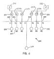
- FIG. 7 is a schematic diagram of a fluidic microchip for performing multiple serial dilutions in accordance with another embodiment of this invention.
- a microfabricated device in accordance with the present invention is described in connection with a number of embodiments.
- the embodiments of this invention demonstrate the mixing of two or more reagent materials by way of a series of tributary channel junctions wherein at least two tributary reagent microchannels communicate with a common mixing microchannel.
- the tributary reagent channels have the same cross sectional area but different lengths and, therefore different flow resistances.
- a comparable device could be fabricated using similar channel lengths but different cross-sectional areas or a combination of the two strategies.
- the amount of reagent supplied by each tributary channel is dependent upon the ratio of the channel lengths and the transport properties of the materials within the channels.
- material in the tributary reagent channels is mixed at a common junction.
- the amount of reagent supplied by each tributary channel is dependent upon the ratio of the channel lengths.
- the design approach for this embodiment can handle all the flow division on the microchip without using techniques external to the microchip.
- the mixing of two or more materials is achieved using pressure driven transport of the fluidic materials.
- a microfabricated device employing a valve that is capable of dispensing variable quantities of a sample material.
- a microfabricated device is provided for performing a plurality of dilution experiments with a minimized number of reagent and diluent material reservoirs and a reduced number of pressure sources.
- a mixing junction or “tee” 10 includes a sample reservoir 20 , buffer reservoir 32 , sample channel 26 , buffer channel 28 , a mixing channel 34 , and waste reservoir 36 .
- a single pressure source 29 is applied to the sample reservoir 20 and buffer reservoir 32 to provide a pressure differential relative to waste reservoir 36 , the fluidic materials from the sample reservoir and the buffer reservoir flow into and are mixed in the tee junction 24 in a ratio that is inversely proportional to the flow resistances of the sample channel 26 and buffer channel 28 .
- a pressure source below ambient pressure vacuum
- the flow resistance is directly proportional to the channel lengths.
- the sample and buffer channels have the same lengths and the same cross-sectional areas, the sample and buffer materials are transported to and mixed in equal proportions at junction 24 under the assumption of homogeneous material properties.
- the sample and buffer channels have different lengths, the sample is diluted by the buffer material in a ratio that is proportional to the length of the buffer channel relative to the combined lengths of the sample and buffer channels.
- the cross-sectional areas of the sample and buffer channels can be dimensioned to provide the desired mixing proportions because the flow resistance of the respective channel is inversely proportional to the cross-sectional area of the channel.
- the channel resistance can be selected by adjusting both the channel lengths and the channel cross-sectional areas to provide the desired transport and mixing of the sample and buffer materials.
- the microfabricated device 5 includes a first buffer reservoir 11 , a first sample reservoir 12 , a second buffer reservoir 13 , a second sample reservoir 14 , a third buffer reservoir 16 , a third sample reservoir 17 , and a waste reservoir 18 .
- a first buffer channel 31 a connects the first buffer reservoir 11 with the waste reservoir 18 .
- a second buffer channel 31 b connects the first buffer reservoir 11 with a first sample channel 33 a that is in fluid communication with the first sample reservoir 12 .
- the intersection of the second buffer channel 31 b and first sample channel 33 a forms a “tee” junction 41 with a first waste channel 36 a that is in fluid communication with the waste reservoir 18 .
- the second buffer reservoir 13 is connected to the first and second sample reservoirs 12 and 14 and to the waste reservoir 18 through channels 33 b, 35 a, 35 b, 36 b, 36 c, and 37 a.
- the third buffer reservoir 16 is connected to the second and third sample reservoirs 14 and 17 and to the waste reservoir 18 through channels 37 b, 38 a, 38 b, 39 a, 36 d, and 36 e.
- the dimensions of the channels 31 b, 33 a, 33 b, 35 a, 35 b, 37 a, 37 b, 38 a, 38 b, and 39 a are selected to provide respective flow resistances that result in desired mixing ratios of the various sample and buffer materials at the corresponding junctions 41 , 42 , 43 , 44 , and 45 , for transport to the waste reservoir 18 along the waste channels 36 a, 36 b, 36 c, 36 d, and 36 e, respectively.
- a pressure source (not shown) is connected to the sample and buffer reservoirs 11 , 12 , 13 , 14 , 16 , 17 to provide a pressure differential relative to the waste reservoir 18 to transport the materials through the microchip channel manifold.
- a sub-ambient pressure source can be connected to the waste reservoir 18 to provide a pressure differential relative to the sample and buffer reservoirs 11 , 12 , 13 , 14 , 16 , 17 to draw sample material through the microchannel manifold.
- the device 90 includes a single sample reservoir 92 , a plurality of buffer reservoirs 94 , 96 , 98 , 100 , and 102 , and a waste reservoir 110 .
- the sample material is loaded into the sample reservoir 92 .
- a pressure source (not shown for simplicity) is connected to sample reservoir 92 and the buffer reservoirs 94 , 96 , 98 , 100 , and 102 to provide a pressure differential relative to waste reservoir 110 .
- a sub-ambient pressure source can be connected to waste reservoir 110 .
- a common buffer, reagent, or various buffers or reagents are loaded into the buffer reservoirs 94 - 102 .
- Respective pairs of sample channels 91 a, 91 b, 93 a, 93 b, 95 a, 95 b, 97 a, 97 b, and 99 a, 99 b interconnect the sample reservoir 92 to each of the plurality of buffer/reagent reservoirs 94 - 102 .
- Corresponding pairs of mixing channels 101 a, 101 b, 103 a, 103 b, 105 a, 105 b, 107 a, 107 b, and 109 a, 109 b interconnect each sample channel with the waste reservoir 110 .
- the mixing channels intersect the sample channels at mixing junctions 111 a, 111 b, 113 a, 113 b, 115 a, 115 b, 117 a, 117 b, and 119 a, 119 b, respectively.
- the arrangement in FIG. 2 a allows a large number of simultaneous, fixed dilutions of the sample material to be performed with one or more buffer solutions.
- the cross-sectional areas and lengths of the channel segments forming the mixing junctions are dimensioned to provide mixing of the sample and buffer materials in different, preselected proportions at each of the mixing junctions.
- the device 90 minimizes the number of reservoirs required to do the multiple dilutions of a single sample within a two dimensional layout, i.e., without crossing of channels.
- N/2+2 reservoirs are required. The value is rounded up to the next higher integer if N is an odd number.
- the plurality of buffer reservoirs are combined into a single reservoir by using sufficiently small vertical access conduits (vias) through the microchannel coverplate and a buffer reservoir having a sufficiently large cross section to access the vias.
- vias could be used to communicate between multiple layers of microchannels to allow the reduction of the plurality of buffer reservoirs into a single reservoir.
- the multiple layers of microchannels would allow channels to cross over the tops of each other similar to the constructs used in multilayer printed circuit boards.
- FIG. 3 A schematic of a microchip 15 according to the present invention that demonstrates valving is depicted in FIG. 3 .
- the microchip 15 includes a sample reservoir 70 , a buffer reservoir 74 , a first waste reservoir 76 , and a second waste reservoir 78 .
- a sample channel 71 has a first end in fluidic communication with the sample reservoir 70 .
- a buffer channel 73 has a first end in fluidic communication with the buffer reservoir 74 .
- a first waste channel 75 has one end in fluidic communication with the first waste reservoir 76 and a second waste channel 77 has an end in fluidic communication with the second waste reservoir 78 .
- the second ends of the four channels meet at a valving junction 80 .
- the lengths of the various channels between the respective reservoirs and the valving junction are selected to provide predetermined flow resistance in the respective channels.
- the sample reservoir 70 is connected to a first pressure source 68
- the buffer reservoir 74 is connected to a second pressure source 72 .
- the valve 80 is closed when the pressures applied by these pressure sources are equal in magnitude.
- the first and second waste reservoirs 76 , 78 are maintained at a lower pressure relative to the pressure sources 68 and 72 .
- valve 80 is closed, the sample material is transported only to the first waste reservoir 76 .
- the valve 80 is actuated or opened by lowering the pressure applied to buffer reservoir 74 relative to the pressure applied to sample reservoir 70 .
- valve 80 is open, the sample material is transported to both first waste reservoir 76 and second waste reservoir 78 .
- the second pressure source 72 includes means for reducing the pressure applied to buffer reservoir 74 .
- Such pressure reducing means may include a pressure reducing valve, a pressure bleed-off valve, or a shut-off valve.
- the pressure reducing means can be electrically and/or computer controlled.
- the pressure source includes a plunger device, such as in a syringe
- pressure reduction is accomplished by slowing, stopping, or retracting the plunger.
- the relative proportions of sample material transported into the first waste channel 75 and the second waste channel 77 are determined according to the relative flow resistances of the respective channels and the relative magnitudes of the first pressure source 68 and second pressure source 72 .
- the valve 80 can be opened by increasing the pressure applied to the sample reservoir 70 relative to the pressure applied to the buffer reservoir 74 .
- this variable volume valve is operated by applying a first sub-ambient pressure (vacuum) source to the first waste reservoir 76 and a second sub-ambient pressure (vacuum) source to the second waste reservoir 78 .
- these vacuum sources provide vacuums that are substantially equal in magnitude to maintain the valve 80 in a “closed” configuration.
- the valve 80 is closed, the sample is transported only to the first waste reservoir 76 .
- the valve 80 is opened by increasing the sub-ambient pressure applied to the first waste reservoir relative to the sub-ambient pressure applied to the second waste reservoir.
- the valve 80 is open, the sample material is transported to the second waste reservoir 78 .
- the valve 80 can be opened by decreasing the sub-ambient pressure (vacuum) applied to the second waste reservoir 78 .
- FIG. 4 A further embodiment for valving in accordance with the present invention is shown in FIG. 4 .
- the device 125 requires fewer fluidic reservoirs to effect valving than the embodiment shown in FIG. 3 and is actuated similar to the first operation mode of that embodiment.
- Microchip device 125 reduces the number of waste reservoirs to one because the waste channel 175 and analysis channel 177 transport the combined sample and buffer materials to a single waste reservoir 178 .
- the buffer channel 173 , sample channel 171 , waste channel 175 , and the analysis channel 177 are dimensioned so as to provide appropriate flows in the four channels that intersect at the valve junction 180 .
- the flow resistances of the channels are preferably designed so that the flow rate in the buffer channel 173 is greater than the flow rate in the analysis channel 177 and the flow rate in the waste channel 175 is greater than the flow rate in the sample channel 171 .
- a first pressure source 168 is connected to the sample reservoir 170 and a second pressure source 172 is connected to the buffer reservoir 174 .
- the valving device 125 is actuated in essentially the same manner as the device shown in FIG. 3 .
- valve 180 when the pressure applied to buffer reservoir 174 is lowered, the valve 180 is opened, and when the pressure applied to buffer reservoir 174 is returned to its initial value, approximately equal to the pressure applied to the sample reservoir 171 , the valve 180 closes.
- the functionality of the valving device 125 can also be accomplished by using separate pressure sources independent of the dimensions of the respective channels.
- microchip structures in FIGS. 3 and 4 can also be actuated with a combination of super-ambient and sub-ambient pressure sources and in combination with electrokinetic fluid transport as described in copending application Ser. No. 09/212,217 now U.S. Pat. No. 6,062,261.
- FIG. 5 there is shown schematically a standard reagent mixing circuit 210 for implementation on a microchip in accordance with the present invention.
- a pressure source (not shown) is connected to R 1 reservoir 211 and R 2 reservoir 212 . Pressure is not applied to the W 1 reservoir 214 , the W 2 reservoir 215 , or the reservoir 219 .
- a first reagent from R 1 reservoir 211 and a second reagent from R 2 reservoir 212 are mixed at T 3 intersection 213 .
- the W 1 reservoir 214 and the W 2 reservoir 215 are used as flow shunts to assist in the delivery of low flow rates of the first and second reagents to the T 3 intersection 213 .
- flow shunts permits a wide range of stable mixing ratios for the reagents with minimal requirements for flow control. Without flow shunts, highly precise pressure sources would be required to reliably pump small volumes of material within the channel manifold. Alternatively, pressure sources can be applied to the W 1 and W 2 reservoirs to balance the flows from the R 1 and R 2 reservoirs and enable up to 100% flows from the R 1 and R 2 reservoirs toward the T 3 intersection.
- the material is transported from the R 1 reservoir 211 , and the flow is split at the T 1 intersection 216 .
- Controlled portions of the first reagent are sent toward the T 3 intersection 213 and the W 1 reservoir 214 .
- the ratio of the split portions is determined by the applied pressures and the flow resistances of the channels leading from the R 1 reservoir 211 and the W 1 reservoir 214 .
- the material transported from the R 2 reservoir 212 is split at the T 2 intersection 217 , with a portion of the material transported toward the T 3 intersection 213 and a second portion transported toward the W 2 reservoir 215 .
- This configuration allows delivery of small volumes of material from either the R 1 reservoir 211 or the R 2 reservoir 212 to the T 3 intersection 213 , where they are mixed, and avoids having to use highly precise pressure sources.
- This flow shunting can also be achieved by applying sub-ambient pressure sources to the waste reservoirs 214 , 215 , and 219 .
- An alternate configuration for the mixing circuit shown in FIG. 5 is to use the W 1 reservoir 214 and the W 2 reservoir 215 to dilute the reagent materials from the R 1 reservoir 211 and the R 2 reservoirs 212 , respectively, prior to their being mixed at the T 3 intersection 213 .
- pressure sources are applied to both the R 1 reservoir 211 and the W 1 reservoir 214 to transport the materials from the respective reservoirs towards the T 1 intersection 216 .
- the amount of dilution of the first reagent by the buffer material in the W 1 reservoir 214 at the T 1 intersection 216 depends on the magnitudes of the pressures applied to the reservoirs and the flow resistances of the respective channels.
- pressure sources are applied to both the R 2 reservoir 212 and the W 2 reservoir 215 to transport the materials from the respective reservoirs toward the T 2 intersection 217 .
- the amount of dilution of the second reagent by the buffer material in the W 2 reservoir 215 at the T 2 intersection 217 depends on the magnitudes of the pressures applied to the respective reservoirs and the flow resistances in the channels.
- FIG. 6 there is shown a modified arrangement for the dilution/mixing circuit shown in FIG. 5 .
- multiple fluid shunts are included to provide increased dynamic range over the dilution of either the first reagent in R 1 reservoir 221 , the second reagent in R 2 reservoir 222 , or both.
- a first pressure source 231 is connected to R 1 reservoir 221 , D 1 reservoir 225 a and the D 3 reservoir 225 b.
- a second pressure source 232 is connected to R 2 reservoir 222 , D 2 reservoir 233 a, and D 4 reservoir 223 b.
- the flow of the first reagent through T 1 intersection 223 operates just as the corresponding intersection of the embodiment shown in FIG. 5 and described above.
- the first and second pressure sources can be combined as a single source.
- the flow of the first reagent from the T 1 intersection toward the T 7 intersection 230 can be further diluted at the T 3 intersection 224 with a first diluent held in D 1 reservoir 225 .
- W 3 reservoir 227 allows a material shunting process to occur similar to that which occurs at the T 1 intersection 223 .
- This serial dilution process can continue with additional fluidic elements that comprise an input channel, an output channel, a diluent channel, and a shunting channel all connected at a four-way intersection.
- the reservoirs and intersections on the right hand side of the T 7 intersection 230 mirror the reservoirs and intersections shown on the left hand side of that intersection.
- the circuit depicted schematically in FIG. 6 allows independent control over all of the reagent, diluent, and waste (shunting) reservoirs for maximal control of the process.
- Each reservoir in FIG. 6 could have an independently controlled pressure source to enable the most flexible operation.
- the diluents would be the same, but they could also be different.
- sub-ambient pressure sources are applied to the waste reservoirs W 1 , W 3 , W 5 , W 2 , W 4 , and W 6 and the main waste reservoir 239 .
- An operationally less complex fluid circuit that can perform a similar dilution function can be produced by making the left-hand-side and right-hand-side diluent and waste reservoirs, respectively common. Such a device is shown in FIG. 7 and described below.
- the microfluidic device of the present invention can be further embodied as a serial diluter.
- a serial diluter according to this invention, a series of channels, tees, and intersections are configured for mixing two reagents (a sample and a buffer) in a series of preselected ratios.
- the desired dilutions correspond to the fluid flow in the various channels of the microchip. Therefore, a microchip for implementing this aspect of the present invention is designed by analyzing the various channels as an equivalent electrical circuit. Each channel or circuit branch has a resistance designed to provide a desired flow therethrough. The sample and buffer materials are transported through the various microchannels in direct proportion to the equivalent current flow.
- FIG. 7 shows a preferred microfluidic circuit 810 for a serial diluter in accordance with this aspect of the present invention.
- the serial diluter circuit 810 includes a buffer reservoir 812 for holding a buffering material or other diluent, a sample reservoir 814 for holding a sample material, a first waste reservoir 816 , and a second waste reservoir 818 .
- a main buffer channel 821 in fluid communication with the buffer reservoir 812 is formed for carrying the buffer material.
- a sample channel 822 is in fluid communication with the sample reservoir 814 for carrying the sample material.
- a plurality of buffer channel extensions 821 a, 822 a, 823 a, and 824 a extend in series from the buffer channel 821 .
- a set of buffer branch channels 821 b, 822 b, 823 b, 824 b, and 825 b each branch off from the buffer channel extensions 821 a, 822 a, 823 a, and 824 a, respectively, at selected locations relative to the intersection with the main buffer channel 821 .
- the sample channel 822 interconnects with the buffer branch channel 821 b at a preselected distance from the intersection with the first buffer extension channel 821 a.
- a mixing channel 821 c interconnects with the buffer branch channel 821 b at the point of intersection with sample channel 822 .
- a series of mixing channels 822 c, 823 c, and 824 c extend from the other end of mixing channel 821 c.
- a set of analysis channels 821 d, 822 d, 823 d, 824 d, and 825 d branch off from the mixing channels 821 c, 822 c, 823 c, and 824 c, respectively, at selected locations relative to the intersection with the branch channel 821 b.
- the analysis channels branch off at respective ends of the mixing channels.
- the analysis channels have different lengths relative to one another and are in fluid communication with the second waste reservoir 818 .
- a waste channel 826 interconnects the end of mixing channel 824 c with the first waste channel 816 .
- the buffer material When a pressure is applied to the buffer reservoir 812 and the sample reservoir 814 that is elevated relative to the waste reservoirs 816 and 818 , the buffer material is transported along buffer channel 821 into buffer channel extension 821 a and buffer branch channel 821 b. The buffer material is similarly transported from buffer branch channel 821 b into mixing channel 821 c. Arrows indicate the buffer flow direction in the drawing. Simultaneously, the sample material is transported along sample channel 822 into mixing channel 821 c and analysis channel 821 d as indicated by the arrows in FIG. 7 .
- the sample material is diluted with the buffer material in mixing channel 821 c, whereas the sample material in analysis channel 821 d is at the same concentration as the sample material in sample channel 822 , i.e., it is undiluted.
- This same flow pattern develops if a sub-ambient pressure (vacuum) is applied to the waste reservoirs 816 and 818 relative to the buffer reservoir 812 and sample reservoir 814 .
- waste reservoir 816 and 818 can be combined into a single reservoir to further simplify the structure.
- the buffer material in buffer extension channel 821 a is split between buffer extension channel 822 a and buffer branch channel 822 b.
- the buffer material in branch channel 822 b flows into mixing channel 822 c and the diluted sample material in mixing channel 821 c is split between mixing channel 822 c and analysis channel 822 d.
- the diluted sample material from mixing channel 821 c is further diluted in mixing channel 822 c, whereas the diluted sample material in analysis channel 822 d is at the same concentration as the diluted sample material in mixing channel 821 c.
- buffer extension channels 823 a and 824 a buffer branch channels 823 b, 824 b, and 825 b, mixing channels 823 c and 824 c, and analysis channels 823 d, 824 d, and 825 d.
- buffer branch channels 823 b, 824 b, and 825 b mixing channels 823 c and 824 c
- analysis channels 823 d, 824 d, and 825 d there are five analysis channels, but the series of channel extensions, channel branches, mixing channels, and analysis channels can continue for as many dilutions as needed for a particular process.
- the channels are formed with essentially the same cross-sectional areas.
- the channel flow resistance is increased by lengthening the channel or decreased by shortening the channel during design and fabrication of the microchip.
- Use of relatively narrow cross sections for the mixing channels is preferred because it allows rapid equilibration of the mixed fluid streams.
- the velocity of the fluid streams is below a limit that allows efficient mixing of the materials in the mixing channels.
- the pressure source can be embodied as any type of device that is known to those skilled in the art to be capable of applying a pressure to the respective reservoir or channel.
- the increasing or decreasing of the pressure source to the reservoir or channel can be embodied as any type of device that is known to those skilled in the art to be capable of such.
- the pressure source is a syringe device or a regulated pressure source that is connected to the device reservoirs with appropriate fittings.
- the sub-ambient pressure (vacuum) source can be embodied as any type of device that is known to those skilled in the art including vacuum pumps or a suction device such as a syringe device operated in a withdraw mode.
- the pressure does not have to be constant for the device to operate.
- the pumping of the fluidic materials can be accomplished with any combination of pressure and vacuum sources, and may even include electrokinetic pumping means, to create pressure differentials using intrachannel connections to effect the flow of the fluidic materials in a desired direction and with a desired flow velocity.
- the fabrication and operability of these intrachannel connections are described in copending application Ser. No. 09/244,914, the entirety of which is incorporated herein by reference.
- the microfabricated device in accordance with the present invention readily provides microfluidic proportioning. Such functionality is useful in analyzing chemical and biological reactions such as kinetics studies requiring the combination of materials in precise volumes.
- the microfabricated device disclosed herein enables the on-chip mixing of materials in different proportions using channels having different flow resistances.
- the microfabricated device includes one or more channel junctions or “tees” having sample and buffer reagent channels that meet at a mixing junction. By having tributary channels with the same cross sectional area but different lengths, the materials traveling therethrough, can be mixed at a junction depending on the ratio of the channel lengths, because the flow resistances of the microfabricated channels are directly proportional to the channel length.
- Microfabricated channels having different cross-sectional areas could also effectively proportion samples, because the microchannel resistance is inversely proportional to cross-sectional area.
- handling of the flow division on the microchip can be accomplished by properly dimensioning the channels of the microfabricated device without using techniques external to the microchip.
- the number of pressure sources needed to operate a microfluidic device can be greatly reduced.
- the number of sample, buffer, and waste reservoirs needed to perform multiple dilutions of a sample material can be significantly reduced.
- the devices described herein can be operated using a combination of pressure and vacuum sources operatively connected to the reservoirs or channels or in combination with functionally equivalent electrokinetic fluid transport mechanisms as described in our co-pending application Ser. No. 09/212,217 now U.S. Pat. No. 6,062,261.
- channel resistance can be varied by altering channel width or height as well as length to facilitate compact microfluidic designs. It is recognized, however, that various modifications such as channel dimension, location, and arrangement are possible within the scope of the invention as claimed.
Abstract
Description
Claims (42)
Priority Applications (1)
| Application Number | Priority Date | Filing Date | Title |
|---|---|---|---|
| US09/557,435 US6213151B1 (en) | 1998-12-16 | 2000-04-25 | Microfluidic circuit designs for performing fluidic manipulations that reduce the number of pumping sources and fluid reservoirs |
Applications Claiming Priority (2)
| Application Number | Priority Date | Filing Date | Title |
|---|---|---|---|
| US09/212,217 US6062261A (en) | 1998-12-16 | 1998-12-16 | MicrofluIdic circuit designs for performing electrokinetic manipulations that reduce the number of voltage sources and fluid reservoirs |
| US09/557,435 US6213151B1 (en) | 1998-12-16 | 2000-04-25 | Microfluidic circuit designs for performing fluidic manipulations that reduce the number of pumping sources and fluid reservoirs |
Related Parent Applications (1)
| Application Number | Title | Priority Date | Filing Date |
|---|---|---|---|
| US09/212,217 Continuation-In-Part US6062261A (en) | 1998-12-16 | 1998-12-16 | MicrofluIdic circuit designs for performing electrokinetic manipulations that reduce the number of voltage sources and fluid reservoirs |
Publications (1)
| Publication Number | Publication Date |
|---|---|
| US6213151B1 true US6213151B1 (en) | 2001-04-10 |
Family
ID=22790069
Family Applications (2)
| Application Number | Title | Priority Date | Filing Date |
|---|---|---|---|
| US09/212,217 Expired - Lifetime US6062261A (en) | 1998-12-16 | 1998-12-16 | MicrofluIdic circuit designs for performing electrokinetic manipulations that reduce the number of voltage sources and fluid reservoirs |
| US09/557,435 Expired - Lifetime US6213151B1 (en) | 1998-12-16 | 2000-04-25 | Microfluidic circuit designs for performing fluidic manipulations that reduce the number of pumping sources and fluid reservoirs |
Family Applications Before (1)
| Application Number | Title | Priority Date | Filing Date |
|---|---|---|---|
| US09/212,217 Expired - Lifetime US6062261A (en) | 1998-12-16 | 1998-12-16 | MicrofluIdic circuit designs for performing electrokinetic manipulations that reduce the number of voltage sources and fluid reservoirs |
Country Status (8)
| Country | Link |
|---|---|
| US (2) | US6062261A (en) |
| EP (1) | EP1151267B1 (en) |
| JP (1) | JP3467696B2 (en) |
| AT (1) | ATE397204T1 (en) |
| AU (1) | AU755246B2 (en) |
| CA (1) | CA2355084C (en) |
| DE (1) | DE69938844D1 (en) |
| WO (1) | WO2000036390A2 (en) |
Cited By (87)
| Publication number | Priority date | Publication date | Assignee | Title |
|---|---|---|---|---|
| WO2002053921A2 (en) * | 2001-01-08 | 2002-07-11 | Nanolab Ltd. | Apparatus and method for propelling fluids |
| US20020125134A1 (en) * | 2001-01-24 | 2002-09-12 | Santiago Juan G. | Electrokinetic instability micromixer |
| US20020195343A1 (en) * | 2001-06-20 | 2002-12-26 | Coventor, Inc. | Microfabricated separation device employing a virtual wall for interfacing fluids |
| US20020197733A1 (en) * | 2001-06-20 | 2002-12-26 | Coventor, Inc. | Microfluidic system including a virtual wall fluid interface port for interfacing fluids with the microfluidic system |
| US20030015425A1 (en) * | 2001-06-20 | 2003-01-23 | Coventor Inc. | Microfluidic system including a virtual wall fluid interface port for interfacing fluids with the microfluidic system |
| WO2003048722A2 (en) * | 2001-10-11 | 2003-06-12 | Lextron Systems, Inc. | Method and apparatus for performing biochemical testing in a microenvironment |
| US20030210607A1 (en) * | 2002-05-08 | 2003-11-13 | Coventor, Inc. | On chip dilution system |
| US20030215863A1 (en) * | 1999-01-28 | 2003-11-20 | Caliper Technologies Corp. | Devices, systems and methods for time domain multiplexing of reagents |
| US6681788B2 (en) * | 2001-01-29 | 2004-01-27 | Caliper Technologies Corp. | Non-mechanical valves for fluidic systems |
| US6695009B2 (en) * | 2000-10-31 | 2004-02-24 | Caliper Technologies Corp. | Microfluidic methods, devices and systems for in situ material concentration |
| US20040055536A1 (en) * | 2002-09-24 | 2004-03-25 | Pramod Kolar | Method and apparatus for non-contact electrostatic actuation of droplets |
| US20040055891A1 (en) * | 2002-09-24 | 2004-03-25 | Pamula Vamsee K. | Methods and apparatus for manipulating droplets by electrowetting-based techniques |
| US20040058450A1 (en) * | 2002-09-24 | 2004-03-25 | Pamula Vamsee K. | Methods and apparatus for manipulating droplets by electrowetting-based techniques |
| US20040091398A1 (en) * | 2001-06-20 | 2004-05-13 | Teragenics, Inc. | Microfluidic system including a virtual wall fluid interface port for interfacing fluids with the microfluidic system |
| US20050005684A1 (en) * | 2000-02-23 | 2005-01-13 | Caliper Life Sciences, Inc. | Multi-reservoir pressure control system |
| US20050041525A1 (en) * | 2003-08-19 | 2005-02-24 | Pugia Michael J. | Mixing in microfluidic devices |
| US20050109396A1 (en) * | 2002-12-04 | 2005-05-26 | Piero Zucchelli | Devices and methods for programmable microscale manipulation of fluids |
| WO2005089944A3 (en) * | 2004-03-17 | 2005-12-08 | Reiner Goetzen | Microfluidic chip |
| US20060006065A1 (en) * | 2004-06-05 | 2006-01-12 | Symyx Technologies, Inc. | Microfluidic fluid distribution manifold for use with multi-channel reactor systems |
| US20060092757A1 (en) * | 2004-10-28 | 2006-05-04 | Cho Yoon-Kyoung | Method of mixing fluids and mixing apparatus adopting the same |
| US20060133190A1 (en) * | 2002-08-02 | 2006-06-22 | Andreas Manz | Powder mixing microchip, system and method |
| US20060159564A1 (en) * | 2004-12-31 | 2006-07-20 | Industrial Technology Research Institute | Microfluidic driving and speed controlling apparatus and application thereof |
| US20060194331A1 (en) * | 2002-09-24 | 2006-08-31 | Duke University | Apparatuses and methods for manipulating droplets on a printed circuit board |
| US20060239861A1 (en) * | 2005-03-24 | 2006-10-26 | Konica Minolta Medical & Graphic, Inc. | Micro total analysis system |
| US20060263264A1 (en) * | 2001-06-20 | 2006-11-23 | Cytonome, Inc | Microfluidic system including a virtual wall fluid interface port for interfacing fluids with the microfluidic system |
| US20070026469A1 (en) * | 2005-07-29 | 2007-02-01 | Martin Fuchs | Devices and methods for enrichment and alteration of circulating tumor cells and other particles |
| US20070026381A1 (en) * | 2005-04-05 | 2007-02-01 | Huang Lotien R | Devices and methods for enrichment and alteration of cells and other particles |
| CN100406881C (en) * | 2005-06-27 | 2008-07-30 | 浙江大学 | Micro flow control chip capillary electrophoresis negative pressure sampling method |
| US20080195020A1 (en) * | 2000-06-02 | 2008-08-14 | Honeywell International Inc. | A flow control system of a cartridge |
| CN100427944C (en) * | 2006-08-25 | 2008-10-22 | 浙江大学 | Ngatively pressurized sampling three-dimensional chip capillary array electrophoresis system |
| US20090054867A1 (en) * | 2002-02-18 | 2009-02-26 | Peter Gravesen | Device for Administering of Medication in Fluid Form |
| US20090110605A1 (en) * | 2007-10-30 | 2009-04-30 | Konica Minolta Holdings, Inc. | Microchemical chip and sample treatment device |
| US20090155123A1 (en) * | 2007-07-13 | 2009-06-18 | Handylab, Inc. | Automated Pipetting Apparatus Having a Combined Liquid Pump and Pipette Head System |
| US20090151792A1 (en) * | 2005-10-28 | 2009-06-18 | Arkray, Inc. | Liquid Feeding Method and Cartridge To Be Used Therein |
| US20090282981A1 (en) * | 2005-07-26 | 2009-11-19 | Nobuyuki Kitamura | Gas Diluter |
| US20090320945A1 (en) * | 2006-07-20 | 2009-12-31 | Cequr Aps | Flow system with a flow restricter |
| US8133671B2 (en) | 2007-07-13 | 2012-03-13 | Handylab, Inc. | Integrated apparatus for performing nucleic acid extraction and diagnostic testing on multiple biological samples |
| US8182763B2 (en) | 2007-07-13 | 2012-05-22 | Handylab, Inc. | Rack for sample tubes and reagent holders |
| US8216530B2 (en) | 2007-07-13 | 2012-07-10 | Handylab, Inc. | Reagent tube |
| USD665095S1 (en) | 2008-07-11 | 2012-08-07 | Handylab, Inc. | Reagent holder |
| US8268246B2 (en) | 2007-08-09 | 2012-09-18 | Advanced Liquid Logic Inc | PCB droplet actuator fabrication |
| US8273308B2 (en) | 2001-03-28 | 2012-09-25 | Handylab, Inc. | Moving microdroplets in a microfluidic device |
| USD669191S1 (en) | 2008-07-14 | 2012-10-16 | Handylab, Inc. | Microfluidic cartridge |
| US8304230B2 (en) | 2002-09-27 | 2012-11-06 | The General Hospital Corporation | Microfluidic device for cell separation and uses thereof |
| US8324372B2 (en) | 2007-07-13 | 2012-12-04 | Handylab, Inc. | Polynucleotide capture materials, and methods of using same |
| US8323584B2 (en) | 2001-09-12 | 2012-12-04 | Handylab, Inc. | Method of controlling a microfluidic device having a reduced number of input and output connections |
| US8323900B2 (en) | 2006-03-24 | 2012-12-04 | Handylab, Inc. | Microfluidic system for amplifying and detecting polynucleotides in parallel |
| US8415103B2 (en) | 2007-07-13 | 2013-04-09 | Handylab, Inc. | Microfluidic cartridge |
| US8420015B2 (en) | 2001-03-28 | 2013-04-16 | Handylab, Inc. | Systems and methods for thermal actuation of microfluidic devices |
| US8440149B2 (en) | 2001-02-14 | 2013-05-14 | Handylab, Inc. | Heat-reduction methods and systems related to microfluidic devices |
| US8473104B2 (en) | 2001-03-28 | 2013-06-25 | Handylab, Inc. | Methods and systems for control of microfluidic devices |
| US8470586B2 (en) | 2004-05-03 | 2013-06-25 | Handylab, Inc. | Processing polynucleotide-containing samples |
| USD692162S1 (en) | 2011-09-30 | 2013-10-22 | Becton, Dickinson And Company | Single piece reagent holder |
| US20130276890A1 (en) * | 2012-04-19 | 2013-10-24 | David J. Beebe | Method And Device For Controlled Laminar Flow Patterning Within A Channel |
| US8617905B2 (en) | 1995-09-15 | 2013-12-31 | The Regents Of The University Of Michigan | Thermal microvalves |
| US8679831B2 (en) | 2003-07-31 | 2014-03-25 | Handylab, Inc. | Processing particle-containing samples |
| US8709787B2 (en) | 2006-11-14 | 2014-04-29 | Handylab, Inc. | Microfluidic cartridge and method of using same |
| US8852862B2 (en) | 2004-05-03 | 2014-10-07 | Handylab, Inc. | Method for processing polynucleotide-containing samples |
| US8883490B2 (en) | 2006-03-24 | 2014-11-11 | Handylab, Inc. | Fluorescence detector for microfluidic diagnostic system |
| US8895311B1 (en) | 2001-03-28 | 2014-11-25 | Handylab, Inc. | Methods and systems for control of general purpose microfluidic devices |
| WO2015009284A1 (en) * | 2013-07-16 | 2015-01-22 | Premium Genetics (Uk) Ltd. | Microfluidic chip |
| US8961764B2 (en) | 2010-10-15 | 2015-02-24 | Lockheed Martin Corporation | Micro fluidic optic design |
| US9040288B2 (en) | 2006-03-24 | 2015-05-26 | Handylab, Inc. | Integrated system for processing microfluidic samples, and method of using the same |
| US9067207B2 (en) | 2009-06-04 | 2015-06-30 | University Of Virginia Patent Foundation | Optical approach for microfluidic DNA electrophoresis detection |
| US9186677B2 (en) | 2007-07-13 | 2015-11-17 | Handylab, Inc. | Integrated apparatus for performing nucleic acid extraction and diagnostic testing on multiple biological samples |
| US9211378B2 (en) | 2010-10-22 | 2015-12-15 | Cequr Sa | Methods and systems for dosing a medicament |
| US9222954B2 (en) | 2011-09-30 | 2015-12-29 | Becton, Dickinson And Company | Unitized reagent strip |
| US9322054B2 (en) | 2012-02-22 | 2016-04-26 | Lockheed Martin Corporation | Microfluidic cartridge |
| US9618139B2 (en) | 2007-07-13 | 2017-04-11 | Handylab, Inc. | Integrated heater and magnetic separator |
| USD787087S1 (en) | 2008-07-14 | 2017-05-16 | Handylab, Inc. | Housing |
| US9765389B2 (en) | 2011-04-15 | 2017-09-19 | Becton, Dickinson And Company | Scanning real-time microfluidic thermocycler and methods for synchronized thermocycling and scanning optical detection |
| US20180311627A1 (en) * | 2015-06-29 | 2018-11-01 | Imec Vzw | Valve-Less Mixing Method and Mixing Device |
| CN110082294A (en) * | 2012-11-19 | 2019-08-02 | 通用医疗公司 | System and method for integrated multiplexing photometering module |
| EP3669980A1 (en) * | 2018-12-20 | 2020-06-24 | IMEC vzw | Microfluidic distribution scheme |
| US10822644B2 (en) | 2012-02-03 | 2020-11-03 | Becton, Dickinson And Company | External files for distribution of molecular diagnostic tests and determination of compatibility between tests |
| US10900066B2 (en) | 2006-03-24 | 2021-01-26 | Handylab, Inc. | Microfluidic system for amplifying and detecting polynucleotides in parallel |
| US11187224B2 (en) | 2013-07-16 | 2021-11-30 | Abs Global, Inc. | Microfluidic chip |
| US11193879B2 (en) | 2010-11-16 | 2021-12-07 | 1087 Systems, Inc. | Use of vibrational spectroscopy for microfluidic liquid measurement |
| US11243494B2 (en) | 2002-07-31 | 2022-02-08 | Abs Global, Inc. | Multiple laminar flow-based particle and cellular separation with laser steering |
| US11320361B2 (en) | 2015-02-19 | 2022-05-03 | 1087 Systems, Inc. | Scanning infrared measurement system |
| US11331670B2 (en) | 2018-05-23 | 2022-05-17 | Abs Global, Inc. | Systems and methods for particle focusing in microchannels |
| US11415503B2 (en) | 2013-10-30 | 2022-08-16 | Abs Global, Inc. | Microfluidic system and method with focused energy apparatus |
| US11453906B2 (en) | 2011-11-04 | 2022-09-27 | Handylab, Inc. | Multiplexed diagnostic detection apparatus and methods |
| US11628439B2 (en) | 2020-01-13 | 2023-04-18 | Abs Global, Inc. | Single-sheath microfluidic chip |
| US11806718B2 (en) | 2006-03-24 | 2023-11-07 | Handylab, Inc. | Fluorescence detector for microfluidic diagnostic system |
| US11889830B2 (en) | 2019-04-18 | 2024-02-06 | Abs Global, Inc. | System and process for continuous addition of cryoprotectant |
| US11959126B2 (en) | 2021-10-07 | 2024-04-16 | Handylab, Inc. | Microfluidic system for amplifying and detecting polynucleotides in parallel |
Families Citing this family (61)
| Publication number | Priority date | Publication date | Assignee | Title |
|---|---|---|---|---|
| WO1998049344A1 (en) * | 1997-04-28 | 1998-11-05 | Lockheed Martin Energy Research Corporation | Method and apparatus for analyzing nucleic acids |
| US6482306B1 (en) | 1998-09-22 | 2002-11-19 | University Of Washington | Meso- and microfluidic continuous flow and stopped flow electroösmotic mixer |
| WO2000046594A1 (en) * | 1999-02-02 | 2000-08-10 | Caliper Technologies Corp. | Methods, devices and systems for characterizing proteins |
| US6500323B1 (en) * | 1999-03-26 | 2002-12-31 | Caliper Technologies Corp. | Methods and software for designing microfluidic devices |
| US6681616B2 (en) * | 2000-02-23 | 2004-01-27 | Caliper Technologies Corp. | Microfluidic viscometer |
| US7040144B2 (en) * | 2000-02-23 | 2006-05-09 | Caliper Life Sciences, Inc. | Microfluidic viscometer |
| AU2001290867A1 (en) * | 2000-09-14 | 2002-03-26 | Caliper Technologies Corp. | Microfluidic devices and methods for performing temperature mediated reactions |
| US20050011761A1 (en) * | 2000-10-31 | 2005-01-20 | Caliper Technologies Corp. | Microfluidic methods, devices and systems for in situ material concentration |
| US20030057092A1 (en) * | 2000-10-31 | 2003-03-27 | Caliper Technologies Corp. | Microfluidic methods, devices and systems for in situ material concentration |
| WO2002040874A1 (en) | 2000-11-16 | 2002-05-23 | California Institute Of Technology | Apparatus and methods for conducting assays and high throughput screening |
| US7670559B2 (en) * | 2001-02-15 | 2010-03-02 | Caliper Life Sciences, Inc. | Microfluidic systems with enhanced detection systems |
| DE60234572D1 (en) * | 2001-02-15 | 2010-01-14 | Caliper Life Sciences Inc | MICROFLUIDIC SYSTEMS WITH IMPROVED DETECTION SYSTEMS |
| US7867776B2 (en) * | 2001-03-02 | 2011-01-11 | Caliper Life Sciences, Inc. | Priming module for microfluidic chips |
| US7150999B1 (en) | 2001-03-09 | 2006-12-19 | Califer Life Sciences, Inc. | Process for filling microfluidic channels |
| EP1384022A4 (en) * | 2001-04-06 | 2004-08-04 | California Inst Of Techn | Nucleic acid amplification utilizing microfluidic devices |
| EP1390624A1 (en) * | 2001-04-25 | 2004-02-25 | President And Fellows Of Harvard College | Fluidic switches and method for controlling flow in fluidic systems |
| US20040208751A1 (en) * | 2001-05-22 | 2004-10-21 | Lazar Juliana M | Microchip integrated multi-channel electroosmotic pumping system |
| US7723123B1 (en) | 2001-06-05 | 2010-05-25 | Caliper Life Sciences, Inc. | Western blot by incorporating an affinity purification zone |
| US20020187564A1 (en) * | 2001-06-08 | 2002-12-12 | Caliper Technologies Corp. | Microfluidic library analysis |
| US6977163B1 (en) | 2001-06-13 | 2005-12-20 | Caliper Life Sciences, Inc. | Methods and systems for performing multiple reactions by interfacial mixing |
| EP1409989B1 (en) * | 2001-07-13 | 2010-04-28 | Caliper Life Sciences, Inc. | Method for separating components of a mixture |
| US6825127B2 (en) | 2001-07-24 | 2004-11-30 | Zarlink Semiconductor Inc. | Micro-fluidic devices |
| US7060171B1 (en) * | 2001-07-31 | 2006-06-13 | Caliper Life Sciences, Inc. | Methods and systems for reducing background signal in assays |
| US7247274B1 (en) | 2001-11-13 | 2007-07-24 | Caliper Technologies Corp. | Prevention of precipitate blockage in microfluidic channels |
| JP4355210B2 (en) * | 2001-11-30 | 2009-10-28 | フルイディグム コーポレイション | Microfluidic device and method of using microfluidic device |
| AU2003224817B2 (en) | 2002-04-01 | 2008-11-06 | Fluidigm Corporation | Microfluidic particle-analysis systems |
| US7312085B2 (en) * | 2002-04-01 | 2007-12-25 | Fluidigm Corporation | Microfluidic particle-analysis systems |
| AU2003228395B2 (en) * | 2002-04-02 | 2006-12-21 | Caliper Life Sciences, Inc. | Methods and apparatus for separation and isolation of components from a biological sample |
| US7161356B1 (en) | 2002-06-05 | 2007-01-09 | Caliper Life Sciences, Inc. | Voltage/current testing equipment for microfluidic devices |
| JP4106977B2 (en) | 2002-06-21 | 2008-06-25 | 株式会社日立製作所 | Analysis chip and analyzer |
| EP2298448A3 (en) | 2002-09-25 | 2012-05-30 | California Institute of Technology | Microfluidic large scale integration |
| WO2004040001A2 (en) | 2002-10-02 | 2004-05-13 | California Institute Of Technology | Microfluidic nucleic acid analysis |
| US7108775B2 (en) * | 2002-11-08 | 2006-09-19 | Applera Corporation | Apparatus and method for confining eluted samples in electrophoresis systems |
| US7189578B1 (en) | 2002-12-02 | 2007-03-13 | Cfd Research Corporation | Methods and systems employing electrothermally induced flow for mixing and cleaning in microsystems |
| US7604965B2 (en) | 2003-04-03 | 2009-10-20 | Fluidigm Corporation | Thermal reaction device and method for using the same |
| US7402229B2 (en) * | 2004-03-31 | 2008-07-22 | Intel Corporation | Fabrication and use of semipermeable membranes and gels for the control of electrolysis in a microfluidic device |
| WO2005100980A2 (en) * | 2004-04-06 | 2005-10-27 | Bio/Data Corporation | Disposable test device with sample volume measurement and mixing methods |
| JP4643973B2 (en) * | 2004-11-08 | 2011-03-02 | 富士フイルム株式会社 | Inspection method of pump operating condition |
| US7815868B1 (en) | 2006-02-28 | 2010-10-19 | Fluidigm Corporation | Microfluidic reaction apparatus for high throughput screening |
| US7641860B2 (en) * | 2006-06-01 | 2010-01-05 | Nanotek, Llc | Modular and reconfigurable multi-stage microreactor cartridge apparatus |
| US7998418B1 (en) | 2006-06-01 | 2011-08-16 | Nanotek, Llc | Evaporator and concentrator in reactor and loading system |
| US7854902B2 (en) * | 2006-08-23 | 2010-12-21 | Nanotek, Llc | Modular and reconfigurable multi-stage high temperature microreactor cartridge apparatus and system for using same |
| WO2008039209A1 (en) * | 2006-09-27 | 2008-04-03 | The Scripps Research Institute | Microfluidic serial dilution circuit |
| US8445546B2 (en) | 2006-10-25 | 2013-05-21 | Revalesio Corporation | Electrokinetically-altered fluids comprising charge-stabilized gas-containing nanostructures |
| AU2014200893B2 (en) * | 2006-10-25 | 2017-01-19 | Revalesio Corporation | Mixing device and output fluids of same |
| WO2008052143A2 (en) | 2006-10-25 | 2008-05-02 | Revalesio Corporation | Mixing device and output fluids of same |
| JP2008122179A (en) * | 2006-11-10 | 2008-05-29 | Konica Minolta Medical & Graphic Inc | Micro-integrated analysis chip and micro-integrated analysis system |
| JP2008122233A (en) * | 2006-11-13 | 2008-05-29 | Konica Minolta Medical & Graphic Inc | Micro-integrated analysis chip and micro-integrated analysis system |
| JP4308246B2 (en) | 2006-12-20 | 2009-08-05 | 京三電機株式会社 | Fuel filter |
| US7799656B2 (en) | 2007-03-15 | 2010-09-21 | Dalsa Semiconductor Inc. | Microchannels for BioMEMS devices |
| US7797988B2 (en) | 2007-03-23 | 2010-09-21 | Advion Biosystems, Inc. | Liquid chromatography-mass spectrometry |
| JP5189201B2 (en) * | 2008-04-02 | 2013-04-24 | アボット ポイント オブ ケア インコーポレイテッド | Virtual separation of bound and free labels in ligand assays to perform immunoassays of biological fluids containing whole blood |
| US7927904B2 (en) | 2009-01-05 | 2011-04-19 | Dalsa Semiconductor Inc. | Method of making BIOMEMS devices |
| US8262880B2 (en) * | 2010-03-09 | 2012-09-11 | Empire Technology Development Llc | Electrokinetic pumping of nonpolar solvents using ionic fluid |
| EP2490005A1 (en) | 2011-02-18 | 2012-08-22 | Koninklijke Philips Electronics N.V. | Microfluidic resistance network and microfluidic device |
| EP2490020A1 (en) * | 2011-02-18 | 2012-08-22 | Koninklijke Philips Electronics N.V. | Measurement chip, microfluidic device and method of measurement chip manufacture |
| TWI499552B (en) * | 2012-12-07 | 2015-09-11 | Univ Nat Cheng Kung | Droplet-generating method and device |
| JP6003772B2 (en) * | 2013-03-29 | 2016-10-05 | ソニー株式会社 | Microchip and manufacturing method of microchip |
| TW201538719A (en) * | 2014-04-08 | 2015-10-16 | Nat Univ Tsing Hua | Cyclic microfluidic chip and method using the same |
| CN107225006B (en) * | 2017-07-03 | 2018-04-03 | 南京岚煜生物科技有限公司 | More flux micro-fluidic chips based on the flowing of active control liquid |
| JP7070679B2 (en) * | 2018-06-29 | 2022-05-18 | 株式会社ニコン | Fluid devices and systems and mixing methods |
Citations (8)
| Publication number | Priority date | Publication date | Assignee | Title |
|---|---|---|---|---|
| US5116471A (en) * | 1991-10-04 | 1992-05-26 | Varian Associates, Inc. | System and method for improving sample concentration in capillary electrophoresis |
| US5126022A (en) * | 1990-02-28 | 1992-06-30 | Soane Tecnologies, Inc. | Method and device for moving molecules by the application of a plurality of electrical fields |
| US5180480A (en) * | 1991-01-28 | 1993-01-19 | Ciba-Geigy Corporation | Apparatus for the preparation of samples, especially for analytical purposes |
| US5328578A (en) * | 1993-06-15 | 1994-07-12 | Hewlett-Packard Company | Capillary electrophoresis with tracking separation field |
| US5376252A (en) * | 1990-05-10 | 1994-12-27 | Pharmacia Biosensor Ab | Microfluidic structure and process for its manufacture |
| US5603351A (en) | 1995-06-07 | 1997-02-18 | David Sarnoff Research Center, Inc. | Method and system for inhibiting cross-contamination in fluids of combinatorial chemistry device |
| US5750015A (en) * | 1990-02-28 | 1998-05-12 | Soane Biosciences | Method and device for moving molecules by the application of a plurality of electrical fields |
| US5858187A (en) * | 1996-09-26 | 1999-01-12 | Lockheed Martin Energy Systems, Inc. | Apparatus and method for performing electrodynamic focusing on a microchip |
Family Cites Families (13)
| Publication number | Priority date | Publication date | Assignee | Title |
|---|---|---|---|---|
| GB2191110B (en) * | 1986-06-06 | 1989-12-06 | Plessey Co Plc | Chromatographic separation device |
| US4908112A (en) * | 1988-06-16 | 1990-03-13 | E. I. Du Pont De Nemours & Co. | Silicon semiconductor wafer for analyzing micronic biological samples |
| US5132012A (en) * | 1988-06-24 | 1992-07-21 | Hitachi, Ltd. | Liquid chromatograph |
| EP0356160A3 (en) * | 1988-08-24 | 1991-09-11 | The Board Of Trustees Of The Leland Stanford Junior University | Capillary device |
| US5073239A (en) * | 1990-01-24 | 1991-12-17 | Bio-Rad Laboratories, Inc. | Fluid introduction into a capillary by electroendosmosis |
| US5141621A (en) * | 1990-01-26 | 1992-08-25 | The Board Of Trustees Of The Leland Stanford Junior University | Capillary electrophoresis injection device and method |
| US5092973A (en) * | 1990-01-26 | 1992-03-03 | The Board Of Trustees Of The Leland Stanford Junior University | Rectangular capillaries for capillary electrophoresis |
| US5110431A (en) * | 1990-02-28 | 1992-05-05 | Applied Biosystems, Inc. | On-capillary gap junction for fluorescence detection in capillary electrophoresis |
| DE59105165D1 (en) * | 1990-11-01 | 1995-05-18 | Ciba Geigy Ag | Device for the preparation or preparation of liquid samples for chemical analysis. |
| EP0544969B1 (en) * | 1991-12-06 | 1997-03-05 | Ciba-Geigy Ag | Apparatus and method for electrophoretic separation |
| EP0620432B1 (en) * | 1993-04-15 | 2004-08-25 | Zeptosens AG | Method for controlling sample introduction in microcolumn separation techniques and sampling device |
| US6001229A (en) * | 1994-08-01 | 1999-12-14 | Lockheed Martin Energy Systems, Inc. | Apparatus and method for performing microfluidic manipulations for chemical analysis |
| DE69530669T2 (en) * | 1995-02-18 | 2003-11-27 | Agilent Technologies Deutschla | Mixing liquids using electroosmosis |
-
1998
- 1998-12-16 US US09/212,217 patent/US6062261A/en not_active Expired - Lifetime
-
1999
- 1999-12-15 WO PCT/US1999/029741 patent/WO2000036390A2/en active IP Right Grant
- 1999-12-15 JP JP2000588583A patent/JP3467696B2/en not_active Expired - Fee Related
- 1999-12-15 AT AT99969278T patent/ATE397204T1/en not_active IP Right Cessation
- 1999-12-15 DE DE69938844T patent/DE69938844D1/en not_active Expired - Lifetime
- 1999-12-15 AU AU28445/00A patent/AU755246B2/en not_active Ceased
- 1999-12-15 EP EP99969278A patent/EP1151267B1/en not_active Expired - Lifetime
- 1999-12-15 CA CA002355084A patent/CA2355084C/en not_active Expired - Fee Related
-
2000
- 2000-04-25 US US09/557,435 patent/US6213151B1/en not_active Expired - Lifetime
Patent Citations (8)
| Publication number | Priority date | Publication date | Assignee | Title |
|---|---|---|---|---|
| US5126022A (en) * | 1990-02-28 | 1992-06-30 | Soane Tecnologies, Inc. | Method and device for moving molecules by the application of a plurality of electrical fields |
| US5750015A (en) * | 1990-02-28 | 1998-05-12 | Soane Biosciences | Method and device for moving molecules by the application of a plurality of electrical fields |
| US5376252A (en) * | 1990-05-10 | 1994-12-27 | Pharmacia Biosensor Ab | Microfluidic structure and process for its manufacture |
| US5180480A (en) * | 1991-01-28 | 1993-01-19 | Ciba-Geigy Corporation | Apparatus for the preparation of samples, especially for analytical purposes |
| US5116471A (en) * | 1991-10-04 | 1992-05-26 | Varian Associates, Inc. | System and method for improving sample concentration in capillary electrophoresis |
| US5328578A (en) * | 1993-06-15 | 1994-07-12 | Hewlett-Packard Company | Capillary electrophoresis with tracking separation field |
| US5603351A (en) | 1995-06-07 | 1997-02-18 | David Sarnoff Research Center, Inc. | Method and system for inhibiting cross-contamination in fluids of combinatorial chemistry device |
| US5858187A (en) * | 1996-09-26 | 1999-01-12 | Lockheed Martin Energy Systems, Inc. | Apparatus and method for performing electrodynamic focusing on a microchip |
Cited By (224)
| Publication number | Priority date | Publication date | Assignee | Title |
|---|---|---|---|---|
| US8617905B2 (en) | 1995-09-15 | 2013-12-31 | The Regents Of The University Of Michigan | Thermal microvalves |
| US7276330B2 (en) | 1999-01-28 | 2007-10-02 | Caliper Technologies Corp. | Devices, systems and methods for time domain multiplexing of reagents |
| US20030215863A1 (en) * | 1999-01-28 | 2003-11-20 | Caliper Technologies Corp. | Devices, systems and methods for time domain multiplexing of reagents |
| US20050005684A1 (en) * | 2000-02-23 | 2005-01-13 | Caliper Life Sciences, Inc. | Multi-reservoir pressure control system |
| US7171983B2 (en) * | 2000-02-23 | 2007-02-06 | Caliper Life Sciences, Inc. | Multi-reservoir pressure control system |
| US20070157973A1 (en) * | 2000-02-23 | 2007-07-12 | Caliper Life Sciences, Inc. | Multi-reservoir pressure control system |
| US7420659B1 (en) * | 2000-06-02 | 2008-09-02 | Honeywell Interantional Inc. | Flow control system of a cartridge |
| US20080195020A1 (en) * | 2000-06-02 | 2008-08-14 | Honeywell International Inc. | A flow control system of a cartridge |
| US6695009B2 (en) * | 2000-10-31 | 2004-02-24 | Caliper Technologies Corp. | Microfluidic methods, devices and systems for in situ material concentration |
| WO2002053921A3 (en) * | 2001-01-08 | 2002-12-12 | Nanolab Ltd | Apparatus and method for propelling fluids |
| WO2002053921A2 (en) * | 2001-01-08 | 2002-07-11 | Nanolab Ltd. | Apparatus and method for propelling fluids |
| US6453928B1 (en) * | 2001-01-08 | 2002-09-24 | Nanolab Ltd. | Apparatus, and method for propelling fluids |
| US7070681B2 (en) | 2001-01-24 | 2006-07-04 | The Board Of Trustees Of The Leland Stanford Junior University | Electrokinetic instability micromixer |
| US20020125134A1 (en) * | 2001-01-24 | 2002-09-12 | Santiago Juan G. | Electrokinetic instability micromixer |
| US6681788B2 (en) * | 2001-01-29 | 2004-01-27 | Caliper Technologies Corp. | Non-mechanical valves for fluidic systems |
| US8734733B2 (en) | 2001-02-14 | 2014-05-27 | Handylab, Inc. | Heat-reduction methods and systems related to microfluidic devices |
| US9528142B2 (en) | 2001-02-14 | 2016-12-27 | Handylab, Inc. | Heat-reduction methods and systems related to microfluidic devices |
| US9051604B2 (en) | 2001-02-14 | 2015-06-09 | Handylab, Inc. | Heat-reduction methods and systems related to microfluidic devices |
| US8440149B2 (en) | 2001-02-14 | 2013-05-14 | Handylab, Inc. | Heat-reduction methods and systems related to microfluidic devices |
| US8894947B2 (en) | 2001-03-28 | 2014-11-25 | Handylab, Inc. | Systems and methods for thermal actuation of microfluidic devices |
| US8703069B2 (en) | 2001-03-28 | 2014-04-22 | Handylab, Inc. | Moving microdroplets in a microfluidic device |
| US10619191B2 (en) | 2001-03-28 | 2020-04-14 | Handylab, Inc. | Systems and methods for thermal actuation of microfluidic devices |
| US8768517B2 (en) | 2001-03-28 | 2014-07-01 | Handylab, Inc. | Methods and systems for control of microfluidic devices |
| US10571935B2 (en) | 2001-03-28 | 2020-02-25 | Handylab, Inc. | Methods and systems for control of general purpose microfluidic devices |
| US10351901B2 (en) | 2001-03-28 | 2019-07-16 | Handylab, Inc. | Systems and methods for thermal actuation of microfluidic devices |
| US8420015B2 (en) | 2001-03-28 | 2013-04-16 | Handylab, Inc. | Systems and methods for thermal actuation of microfluidic devices |
| US8273308B2 (en) | 2001-03-28 | 2012-09-25 | Handylab, Inc. | Moving microdroplets in a microfluidic device |
| US8473104B2 (en) | 2001-03-28 | 2013-06-25 | Handylab, Inc. | Methods and systems for control of microfluidic devices |
| US8895311B1 (en) | 2001-03-28 | 2014-11-25 | Handylab, Inc. | Methods and systems for control of general purpose microfluidic devices |
| US9677121B2 (en) | 2001-03-28 | 2017-06-13 | Handylab, Inc. | Systems and methods for thermal actuation of microfluidic devices |
| US9259735B2 (en) | 2001-03-28 | 2016-02-16 | Handylab, Inc. | Methods and systems for control of microfluidic devices |
| US20030015425A1 (en) * | 2001-06-20 | 2003-01-23 | Coventor Inc. | Microfluidic system including a virtual wall fluid interface port for interfacing fluids with the microfluidic system |
| US20020195343A1 (en) * | 2001-06-20 | 2002-12-26 | Coventor, Inc. | Microfabricated separation device employing a virtual wall for interfacing fluids |
| US7179423B2 (en) | 2001-06-20 | 2007-02-20 | Cytonome, Inc. | Microfluidic system including a virtual wall fluid interface port for interfacing fluids with the microfluidic system |
| US7211442B2 (en) | 2001-06-20 | 2007-05-01 | Cytonome, Inc. | Microfluidic system including a virtual wall fluid interface port for interfacing fluids with the microfluidic system |
| US20020197733A1 (en) * | 2001-06-20 | 2002-12-26 | Coventor, Inc. | Microfluidic system including a virtual wall fluid interface port for interfacing fluids with the microfluidic system |
| US20070148777A1 (en) * | 2001-06-20 | 2007-06-28 | Cytonome, Inc. | Microfluidic system including a virtual wall fluid interface port for interfacing fluids with the microfluidic system |
| US20060263264A1 (en) * | 2001-06-20 | 2006-11-23 | Cytonome, Inc | Microfluidic system including a virtual wall fluid interface port for interfacing fluids with the microfluidic system |
| US20040091398A1 (en) * | 2001-06-20 | 2004-05-13 | Teragenics, Inc. | Microfluidic system including a virtual wall fluid interface port for interfacing fluids with the microfluidic system |
| US8323584B2 (en) | 2001-09-12 | 2012-12-04 | Handylab, Inc. | Method of controlling a microfluidic device having a reduced number of input and output connections |
| US9028773B2 (en) | 2001-09-12 | 2015-05-12 | Handylab, Inc. | Microfluidic devices having a reduced number of input and output connections |
| US8685341B2 (en) | 2001-09-12 | 2014-04-01 | Handylab, Inc. | Microfluidic devices having a reduced number of input and output connections |
| WO2003048722A2 (en) * | 2001-10-11 | 2003-06-12 | Lextron Systems, Inc. | Method and apparatus for performing biochemical testing in a microenvironment |
| WO2003048722A3 (en) * | 2001-10-11 | 2009-06-11 | Lextron Systems Inc | Method and apparatus for performing biochemical testing in a microenvironment |
| US20090054867A1 (en) * | 2002-02-18 | 2009-02-26 | Peter Gravesen | Device for Administering of Medication in Fluid Form |
| US8945064B2 (en) | 2002-02-18 | 2015-02-03 | Cequr Sa | Device for administering of medication in fluid form |
| US6883957B2 (en) | 2002-05-08 | 2005-04-26 | Cytonome, Inc. | On chip dilution system |
| US7401972B2 (en) | 2002-05-08 | 2008-07-22 | Cytonome, Inc. | On chip dilution system |
| US20050148082A1 (en) * | 2002-05-08 | 2005-07-07 | Cytonome, Inc. | On chip dilution system |
| US20030210607A1 (en) * | 2002-05-08 | 2003-11-13 | Coventor, Inc. | On chip dilution system |
| US11422504B2 (en) | 2002-07-31 | 2022-08-23 | Abs Global, Inc. | Multiple laminar flow-based particle and cellular separation with laser steering |
| US11243494B2 (en) | 2002-07-31 | 2022-02-08 | Abs Global, Inc. | Multiple laminar flow-based particle and cellular separation with laser steering |
| US11415936B2 (en) | 2002-07-31 | 2022-08-16 | Abs Global, Inc. | Multiple laminar flow-based particle and cellular separation with laser steering |
| US20060133190A1 (en) * | 2002-08-02 | 2006-06-22 | Andreas Manz | Powder mixing microchip, system and method |
| US8388909B2 (en) | 2002-09-24 | 2013-03-05 | Duke University | Apparatuses and methods for manipulating droplets |
| US20040055536A1 (en) * | 2002-09-24 | 2004-03-25 | Pramod Kolar | Method and apparatus for non-contact electrostatic actuation of droplets |
| US8524506B2 (en) | 2002-09-24 | 2013-09-03 | Duke University | Methods for sampling a liquid flow |
| US7329545B2 (en) | 2002-09-24 | 2008-02-12 | Duke University | Methods for sampling a liquid flow |
| US20040055891A1 (en) * | 2002-09-24 | 2004-03-25 | Pamula Vamsee K. | Methods and apparatus for manipulating droplets by electrowetting-based techniques |
| US9638662B2 (en) | 2002-09-24 | 2017-05-02 | Duke University | Apparatuses and methods for manipulating droplets |
| US20040058450A1 (en) * | 2002-09-24 | 2004-03-25 | Pamula Vamsee K. | Methods and apparatus for manipulating droplets by electrowetting-based techniques |
| US6911132B2 (en) | 2002-09-24 | 2005-06-28 | Duke University | Apparatus for manipulating droplets by electrowetting-based techniques |
| US8394249B2 (en) | 2002-09-24 | 2013-03-12 | Duke University | Methods for manipulating droplets by electrowetting-based techniques |
| US9180450B2 (en) | 2002-09-24 | 2015-11-10 | Advanced Liquid Logic, Inc. | Droplet manipulation system and method |
| US9110017B2 (en) | 2002-09-24 | 2015-08-18 | Duke University | Apparatuses and methods for manipulating droplets |
| US20080105549A1 (en) * | 2002-09-24 | 2008-05-08 | Pamela Vamsee K | Methods for performing microfluidic sampling |
| US8349276B2 (en) | 2002-09-24 | 2013-01-08 | Duke University | Apparatuses and methods for manipulating droplets on a printed circuit board |
| US6989234B2 (en) | 2002-09-24 | 2006-01-24 | Duke University | Method and apparatus for non-contact electrostatic actuation of droplets |
| US20060194331A1 (en) * | 2002-09-24 | 2006-08-31 | Duke University | Apparatuses and methods for manipulating droplets on a printed circuit board |
| US8221605B2 (en) | 2002-09-24 | 2012-07-17 | Duke University | Apparatus for manipulating droplets |
| US8906627B2 (en) | 2002-09-24 | 2014-12-09 | Duke University | Apparatuses and methods for manipulating droplets |
| US8871071B2 (en) | 2002-09-24 | 2014-10-28 | Duke University | Droplet manipulation device |
| US20090260988A1 (en) * | 2002-09-24 | 2009-10-22 | Duke University | Methods for Manipulating Droplets by Electrowetting-Based Techniques |
| US10081014B2 (en) | 2002-09-27 | 2018-09-25 | The General Hospital Corporation | Microfluidic device for cell separation and uses thereof |
| US8372579B2 (en) | 2002-09-27 | 2013-02-12 | The General Hospital Corporation | Microfluidic device for cell separation and uses thereof |
| US8895298B2 (en) | 2002-09-27 | 2014-11-25 | The General Hospital Corporation | Microfluidic device for cell separation and uses thereof |
| US8986966B2 (en) | 2002-09-27 | 2015-03-24 | The General Hospital Corporation | Microfluidic device for cell separation and uses thereof |
| US11052392B2 (en) | 2002-09-27 | 2021-07-06 | The General Hospital Corporation | Microfluidic device for cell separation and uses thereof |
| US8304230B2 (en) | 2002-09-27 | 2012-11-06 | The General Hospital Corporation | Microfluidic device for cell separation and uses thereof |
| US7152616B2 (en) | 2002-12-04 | 2006-12-26 | Spinx, Inc. | Devices and methods for programmable microscale manipulation of fluids |
| US20050109396A1 (en) * | 2002-12-04 | 2005-05-26 | Piero Zucchelli | Devices and methods for programmable microscale manipulation of fluids |
| US8679831B2 (en) | 2003-07-31 | 2014-03-25 | Handylab, Inc. | Processing particle-containing samples |
| US10865437B2 (en) | 2003-07-31 | 2020-12-15 | Handylab, Inc. | Processing particle-containing samples |
| US11078523B2 (en) | 2003-07-31 | 2021-08-03 | Handylab, Inc. | Processing particle-containing samples |
| US9670528B2 (en) | 2003-07-31 | 2017-06-06 | Handylab, Inc. | Processing particle-containing samples |
| US10731201B2 (en) | 2003-07-31 | 2020-08-04 | Handylab, Inc. | Processing particle-containing samples |
| US20050041525A1 (en) * | 2003-08-19 | 2005-02-24 | Pugia Michael J. | Mixing in microfluidic devices |
| US7347617B2 (en) * | 2003-08-19 | 2008-03-25 | Siemens Healthcare Diagnostics Inc. | Mixing in microfluidic devices |
| WO2005089944A3 (en) * | 2004-03-17 | 2005-12-08 | Reiner Goetzen | Microfluidic chip |
| US7718127B2 (en) | 2004-03-17 | 2010-05-18 | microTec Gesellschaft für Mikrotechnologie mbH | Microfluidic chip |
| US20080025888A1 (en) * | 2004-03-17 | 2008-01-31 | Reiner Gotzen | Microfluidic Chip |
| US10604788B2 (en) | 2004-05-03 | 2020-03-31 | Handylab, Inc. | System for processing polynucleotide-containing samples |
| US10494663B1 (en) | 2004-05-03 | 2019-12-03 | Handylab, Inc. | Method for processing polynucleotide-containing samples |
| US8470586B2 (en) | 2004-05-03 | 2013-06-25 | Handylab, Inc. | Processing polynucleotide-containing samples |
| US11441171B2 (en) | 2004-05-03 | 2022-09-13 | Handylab, Inc. | Method for processing polynucleotide-containing samples |
| US10364456B2 (en) | 2004-05-03 | 2019-07-30 | Handylab, Inc. | Method for processing polynucleotide-containing samples |
| US10443088B1 (en) | 2004-05-03 | 2019-10-15 | Handylab, Inc. | Method for processing polynucleotide-containing samples |
| US8852862B2 (en) | 2004-05-03 | 2014-10-07 | Handylab, Inc. | Method for processing polynucleotide-containing samples |
| US7758814B2 (en) | 2004-06-05 | 2010-07-20 | Freeslate, Inc. | Microfluidic fluid distribution manifold for use with multi-channel reactor systems |
| US20060006065A1 (en) * | 2004-06-05 | 2006-01-12 | Symyx Technologies, Inc. | Microfluidic fluid distribution manifold for use with multi-channel reactor systems |
| US7927552B2 (en) | 2004-10-28 | 2011-04-19 | Samsung Electronics Co., Ltd. | Method of mixing fluids and mixing apparatus adopting the same |
| US20060092757A1 (en) * | 2004-10-28 | 2006-05-04 | Cho Yoon-Kyoung | Method of mixing fluids and mixing apparatus adopting the same |
| US7509906B2 (en) * | 2004-12-31 | 2009-03-31 | Industrial Technology Research Institute | Microfluidic driving and speed controlling apparatus and application thereof |
| US20060159564A1 (en) * | 2004-12-31 | 2006-07-20 | Industrial Technology Research Institute | Microfluidic driving and speed controlling apparatus and application thereof |
| US7727478B2 (en) | 2005-03-24 | 2010-06-01 | Konica Minolta Medical & Graphic, Inc. | Micro total analysis system |
| US20060239861A1 (en) * | 2005-03-24 | 2006-10-26 | Konica Minolta Medical & Graphic, Inc. | Micro total analysis system |
| EP1705543A3 (en) * | 2005-03-24 | 2007-05-30 | Konica Minolta Medical & Graphic, Inc. | Micro total analysis system |
| US20070026381A1 (en) * | 2005-04-05 | 2007-02-01 | Huang Lotien R | Devices and methods for enrichment and alteration of cells and other particles |
| US8021614B2 (en) | 2005-04-05 | 2011-09-20 | The General Hospital Corporation | Devices and methods for enrichment and alteration of cells and other particles |
| US9174222B2 (en) | 2005-04-05 | 2015-11-03 | The General Hospital Corporation | Devices and method for enrichment and alteration of cells and other particles |
| US9956562B2 (en) | 2005-04-05 | 2018-05-01 | The General Hospital Corporation | Devices and method for enrichment and alteration of cells and other particles |
| US8585971B2 (en) | 2005-04-05 | 2013-11-19 | The General Hospital Corporation | Devices and method for enrichment and alteration of cells and other particles |
| US10786817B2 (en) | 2005-04-05 | 2020-09-29 | The General Hospital Corporation | Devices and method for enrichment and alteration of cells and other particles |
| CN100406881C (en) * | 2005-06-27 | 2008-07-30 | 浙江大学 | Micro flow control chip capillary electrophoresis negative pressure sampling method |
| US20090282981A1 (en) * | 2005-07-26 | 2009-11-19 | Nobuyuki Kitamura | Gas Diluter |
| US8668377B2 (en) * | 2005-07-26 | 2014-03-11 | Toyota Jidosha Kabushiki Kaisha | Gas diluter |
| US20070026469A1 (en) * | 2005-07-29 | 2007-02-01 | Martin Fuchs | Devices and methods for enrichment and alteration of circulating tumor cells and other particles |
| US8921102B2 (en) | 2005-07-29 | 2014-12-30 | Gpb Scientific, Llc | Devices and methods for enrichment and alteration of circulating tumor cells and other particles |
| US8172455B2 (en) * | 2005-10-28 | 2012-05-08 | Arkray, Inc. | Liquid feeding method and cartridge to be used therein |
| US20090151792A1 (en) * | 2005-10-28 | 2009-06-18 | Arkray, Inc. | Liquid Feeding Method and Cartridge To Be Used Therein |
| US9080207B2 (en) | 2006-03-24 | 2015-07-14 | Handylab, Inc. | Microfluidic system for amplifying and detecting polynucleotides in parallel |
| US10695764B2 (en) | 2006-03-24 | 2020-06-30 | Handylab, Inc. | Fluorescence detector for microfluidic diagnostic system |
| US10843188B2 (en) | 2006-03-24 | 2020-11-24 | Handylab, Inc. | Integrated system for processing microfluidic samples, and method of using the same |
| US9802199B2 (en) | 2006-03-24 | 2017-10-31 | Handylab, Inc. | Fluorescence detector for microfluidic diagnostic system |
| US10821446B1 (en) | 2006-03-24 | 2020-11-03 | Handylab, Inc. | Fluorescence detector for microfluidic diagnostic system |
| US10799862B2 (en) | 2006-03-24 | 2020-10-13 | Handylab, Inc. | Integrated system for processing microfluidic samples, and method of using same |
| US10857535B2 (en) | 2006-03-24 | 2020-12-08 | Handylab, Inc. | Integrated system for processing microfluidic samples, and method of using same |
| US9040288B2 (en) | 2006-03-24 | 2015-05-26 | Handylab, Inc. | Integrated system for processing microfluidic samples, and method of using the same |
| US10900066B2 (en) | 2006-03-24 | 2021-01-26 | Handylab, Inc. | Microfluidic system for amplifying and detecting polynucleotides in parallel |
| US10913061B2 (en) | 2006-03-24 | 2021-02-09 | Handylab, Inc. | Integrated system for processing microfluidic samples, and method of using the same |
| US11806718B2 (en) | 2006-03-24 | 2023-11-07 | Handylab, Inc. | Fluorescence detector for microfluidic diagnostic system |
| US10821436B2 (en) | 2006-03-24 | 2020-11-03 | Handylab, Inc. | Integrated system for processing microfluidic samples, and method of using the same |
| US11085069B2 (en) | 2006-03-24 | 2021-08-10 | Handylab, Inc. | Microfluidic system for amplifying and detecting polynucleotides in parallel |
| US11666903B2 (en) | 2006-03-24 | 2023-06-06 | Handylab, Inc. | Integrated system for processing microfluidic samples, and method of using same |
| US11141734B2 (en) | 2006-03-24 | 2021-10-12 | Handylab, Inc. | Fluorescence detector for microfluidic diagnostic system |
| US11142785B2 (en) | 2006-03-24 | 2021-10-12 | Handylab, Inc. | Microfluidic system for amplifying and detecting polynucleotides in parallel |
| US8883490B2 (en) | 2006-03-24 | 2014-11-11 | Handylab, Inc. | Fluorescence detector for microfluidic diagnostic system |
| US8323900B2 (en) | 2006-03-24 | 2012-12-04 | Handylab, Inc. | Microfluidic system for amplifying and detecting polynucleotides in parallel |
| US20090320945A1 (en) * | 2006-07-20 | 2009-12-31 | Cequr Aps | Flow system with a flow restricter |
| CN100427944C (en) * | 2006-08-25 | 2008-10-22 | 浙江大学 | Ngatively pressurized sampling three-dimensional chip capillary array electrophoresis system |
| US8765076B2 (en) | 2006-11-14 | 2014-07-01 | Handylab, Inc. | Microfluidic valve and method of making same |
| US8709787B2 (en) | 2006-11-14 | 2014-04-29 | Handylab, Inc. | Microfluidic cartridge and method of using same |
| US10710069B2 (en) | 2006-11-14 | 2020-07-14 | Handylab, Inc. | Microfluidic valve and method of making same |
| US9815057B2 (en) | 2006-11-14 | 2017-11-14 | Handylab, Inc. | Microfluidic cartridge and method of making same |
| US9217143B2 (en) | 2007-07-13 | 2015-12-22 | Handylab, Inc. | Polynucleotide capture materials, and methods of using same |
| US10590410B2 (en) | 2007-07-13 | 2020-03-17 | Handylab, Inc. | Polynucleotide capture materials, and methods of using same |
| US9701957B2 (en) | 2007-07-13 | 2017-07-11 | Handylab, Inc. | Reagent holder, and kits containing same |
| US8182763B2 (en) | 2007-07-13 | 2012-05-22 | Handylab, Inc. | Rack for sample tubes and reagent holders |
| US11845081B2 (en) | 2007-07-13 | 2023-12-19 | Handylab, Inc. | Integrated apparatus for performing nucleic acid extraction and diagnostic testing on multiple biological samples |
| US10065185B2 (en) | 2007-07-13 | 2018-09-04 | Handylab, Inc. | Microfluidic cartridge |
| US10071376B2 (en) | 2007-07-13 | 2018-09-11 | Handylab, Inc. | Integrated apparatus for performing nucleic acid extraction and diagnostic testing on multiple biological samples |
| US10875022B2 (en) | 2007-07-13 | 2020-12-29 | Handylab, Inc. | Integrated apparatus for performing nucleic acid extraction and diagnostic testing on multiple biological samples |
| US20090155123A1 (en) * | 2007-07-13 | 2009-06-18 | Handylab, Inc. | Automated Pipetting Apparatus Having a Combined Liquid Pump and Pipette Head System |
| US10100302B2 (en) | 2007-07-13 | 2018-10-16 | Handylab, Inc. | Polynucleotide capture materials, and methods of using same |
| US11549959B2 (en) | 2007-07-13 | 2023-01-10 | Handylab, Inc. | Automated pipetting apparatus having a combined liquid pump and pipette head system |
| US11466263B2 (en) | 2007-07-13 | 2022-10-11 | Handylab, Inc. | Diagnostic apparatus to extract nucleic acids including a magnetic assembly and a heater assembly |
| US10139012B2 (en) | 2007-07-13 | 2018-11-27 | Handylab, Inc. | Integrated heater and magnetic separator |
| US10179910B2 (en) | 2007-07-13 | 2019-01-15 | Handylab, Inc. | Rack for sample tubes and reagent holders |
| US10234474B2 (en) | 2007-07-13 | 2019-03-19 | Handylab, Inc. | Automated pipetting apparatus having a combined liquid pump and pipette head system |
| US11060082B2 (en) | 2007-07-13 | 2021-07-13 | Handy Lab, Inc. | Polynucleotide capture materials, and systems using same |
| US8133671B2 (en) | 2007-07-13 | 2012-03-13 | Handylab, Inc. | Integrated apparatus for performing nucleic acid extraction and diagnostic testing on multiple biological samples |
| US8710211B2 (en) | 2007-07-13 | 2014-04-29 | Handylab, Inc. | Polynucleotide capture materials, and methods of using same |
| US10844368B2 (en) | 2007-07-13 | 2020-11-24 | Handylab, Inc. | Diagnostic apparatus to extract nucleic acids including a magnetic assembly and a heater assembly |
| US8415103B2 (en) | 2007-07-13 | 2013-04-09 | Handylab, Inc. | Microfluidic cartridge |
| US9618139B2 (en) | 2007-07-13 | 2017-04-11 | Handylab, Inc. | Integrated heater and magnetic separator |
| US8324372B2 (en) | 2007-07-13 | 2012-12-04 | Handylab, Inc. | Polynucleotide capture materials, and methods of using same |
| US11266987B2 (en) | 2007-07-13 | 2022-03-08 | Handylab, Inc. | Microfluidic cartridge |
| US8216530B2 (en) | 2007-07-13 | 2012-07-10 | Handylab, Inc. | Reagent tube |
| US9347586B2 (en) | 2007-07-13 | 2016-05-24 | Handylab, Inc. | Automated pipetting apparatus having a combined liquid pump and pipette head system |
| US11254927B2 (en) | 2007-07-13 | 2022-02-22 | Handylab, Inc. | Polynucleotide capture materials, and systems using same |
| US10625261B2 (en) | 2007-07-13 | 2020-04-21 | Handylab, Inc. | Integrated apparatus for performing nucleic acid extraction and diagnostic testing on multiple biological samples |
| US10625262B2 (en) | 2007-07-13 | 2020-04-21 | Handylab, Inc. | Integrated apparatus for performing nucleic acid extraction and diagnostic testing on multiple biological samples |
| US10632466B1 (en) | 2007-07-13 | 2020-04-28 | Handylab, Inc. | Integrated apparatus for performing nucleic acid extraction and diagnostic testing on multiple biological samples |
| US8287820B2 (en) | 2007-07-13 | 2012-10-16 | Handylab, Inc. | Automated pipetting apparatus having a combined liquid pump and pipette head system |
| US9186677B2 (en) | 2007-07-13 | 2015-11-17 | Handylab, Inc. | Integrated apparatus for performing nucleic acid extraction and diagnostic testing on multiple biological samples |
| US9259734B2 (en) | 2007-07-13 | 2016-02-16 | Handylab, Inc. | Integrated apparatus for performing nucleic acid extraction and diagnostic testing on multiple biological samples |
| US10717085B2 (en) | 2007-07-13 | 2020-07-21 | Handylab, Inc. | Integrated apparatus for performing nucleic acid extraction and diagnostic testing on multiple biological samples |
| US9238223B2 (en) | 2007-07-13 | 2016-01-19 | Handylab, Inc. | Microfluidic cartridge |
| US8268246B2 (en) | 2007-08-09 | 2012-09-18 | Advanced Liquid Logic Inc | PCB droplet actuator fabrication |
| US20090110605A1 (en) * | 2007-10-30 | 2009-04-30 | Konica Minolta Holdings, Inc. | Microchemical chip and sample treatment device |
| USD665095S1 (en) | 2008-07-11 | 2012-08-07 | Handylab, Inc. | Reagent holder |
| USD787087S1 (en) | 2008-07-14 | 2017-05-16 | Handylab, Inc. | Housing |
| USD669191S1 (en) | 2008-07-14 | 2012-10-16 | Handylab, Inc. | Microfluidic cartridge |
| US9649631B2 (en) | 2009-06-04 | 2017-05-16 | Leidos Innovations Technology, Inc. | Multiple-sample microfluidic chip for DNA analysis |
| US9067207B2 (en) | 2009-06-04 | 2015-06-30 | University Of Virginia Patent Foundation | Optical approach for microfluidic DNA electrophoresis detection |
| US9656261B2 (en) | 2009-06-04 | 2017-05-23 | Leidos Innovations Technology, Inc. | DNA analyzer |
| US8961764B2 (en) | 2010-10-15 | 2015-02-24 | Lockheed Martin Corporation | Micro fluidic optic design |
| US9211378B2 (en) | 2010-10-22 | 2015-12-15 | Cequr Sa | Methods and systems for dosing a medicament |
| US11193879B2 (en) | 2010-11-16 | 2021-12-07 | 1087 Systems, Inc. | Use of vibrational spectroscopy for microfluidic liquid measurement |
| US9765389B2 (en) | 2011-04-15 | 2017-09-19 | Becton, Dickinson And Company | Scanning real-time microfluidic thermocycler and methods for synchronized thermocycling and scanning optical detection |
| US10781482B2 (en) | 2011-04-15 | 2020-09-22 | Becton, Dickinson And Company | Scanning real-time microfluidic thermocycler and methods for synchronized thermocycling and scanning optical detection |
| US11788127B2 (en) | 2011-04-15 | 2023-10-17 | Becton, Dickinson And Company | Scanning real-time microfluidic thermocycler and methods for synchronized thermocycling and scanning optical detection |
| USD742027S1 (en) | 2011-09-30 | 2015-10-27 | Becton, Dickinson And Company | Single piece reagent holder |
| US9480983B2 (en) | 2011-09-30 | 2016-11-01 | Becton, Dickinson And Company | Unitized reagent strip |
| US10076754B2 (en) | 2011-09-30 | 2018-09-18 | Becton, Dickinson And Company | Unitized reagent strip |
| USD692162S1 (en) | 2011-09-30 | 2013-10-22 | Becton, Dickinson And Company | Single piece reagent holder |
| US9222954B2 (en) | 2011-09-30 | 2015-12-29 | Becton, Dickinson And Company | Unitized reagent strip |
| USD831843S1 (en) | 2011-09-30 | 2018-10-23 | Becton, Dickinson And Company | Single piece reagent holder |
| USD905269S1 (en) | 2011-09-30 | 2020-12-15 | Becton, Dickinson And Company | Single piece reagent holder |
| US11453906B2 (en) | 2011-11-04 | 2022-09-27 | Handylab, Inc. | Multiplexed diagnostic detection apparatus and methods |
| US10822644B2 (en) | 2012-02-03 | 2020-11-03 | Becton, Dickinson And Company | External files for distribution of molecular diagnostic tests and determination of compatibility between tests |
| US9988676B2 (en) | 2012-02-22 | 2018-06-05 | Leidos Innovations Technology, Inc. | Microfluidic cartridge |
| US9322054B2 (en) | 2012-02-22 | 2016-04-26 | Lockheed Martin Corporation | Microfluidic cartridge |
| US9103502B2 (en) * | 2012-04-19 | 2015-08-11 | Wisconsin Alumni Research Foundation | Method and device for controlled laminar flow patterning within a channel |
| US20130276890A1 (en) * | 2012-04-19 | 2013-10-24 | David J. Beebe | Method And Device For Controlled Laminar Flow Patterning Within A Channel |
| CN110082294A (en) * | 2012-11-19 | 2019-08-02 | 通用医疗公司 | System and method for integrated multiplexing photometering module |
| US11512691B2 (en) | 2013-07-16 | 2022-11-29 | Abs Global, Inc. | Microfluidic chip |
| WO2015009284A1 (en) * | 2013-07-16 | 2015-01-22 | Premium Genetics (Uk) Ltd. | Microfluidic chip |
| CN105556279A (en) * | 2013-07-16 | 2016-05-04 | 普里米欧姆遗传学(英国)有限公司 | Microfluidic chip |
| CN105556279B (en) * | 2013-07-16 | 2019-11-26 | 普里米欧姆遗传学(英国)有限公司 | Micro-fluid chip |
| US11187224B2 (en) | 2013-07-16 | 2021-11-30 | Abs Global, Inc. | Microfluidic chip |
| US11415503B2 (en) | 2013-10-30 | 2022-08-16 | Abs Global, Inc. | Microfluidic system and method with focused energy apparatus |
| US11796449B2 (en) | 2013-10-30 | 2023-10-24 | Abs Global, Inc. | Microfluidic system and method with focused energy apparatus |
| US11639888B2 (en) | 2013-10-30 | 2023-05-02 | Abs Global, Inc. | Microfluidic system and method with focused energy apparatus |
| US11674882B2 (en) | 2015-02-19 | 2023-06-13 | 1087 Systems, Inc. | Scanning infrared measurement system |
| US11320361B2 (en) | 2015-02-19 | 2022-05-03 | 1087 Systems, Inc. | Scanning infrared measurement system |
| US20180311627A1 (en) * | 2015-06-29 | 2018-11-01 | Imec Vzw | Valve-Less Mixing Method and Mixing Device |
| US10537862B2 (en) * | 2015-06-29 | 2020-01-21 | Imec Vzw | Valve-less mixing method and mixing device |
| US11331670B2 (en) | 2018-05-23 | 2022-05-17 | Abs Global, Inc. | Systems and methods for particle focusing in microchannels |
| EP3669980A1 (en) * | 2018-12-20 | 2020-06-24 | IMEC vzw | Microfluidic distribution scheme |
| US11471887B2 (en) | 2018-12-20 | 2022-10-18 | Imec Vzw | Microfluidic distribution scheme |
| US11889830B2 (en) | 2019-04-18 | 2024-02-06 | Abs Global, Inc. | System and process for continuous addition of cryoprotectant |
| US11628439B2 (en) | 2020-01-13 | 2023-04-18 | Abs Global, Inc. | Single-sheath microfluidic chip |
| US11959126B2 (en) | 2021-10-07 | 2024-04-16 | Handylab, Inc. | Microfluidic system for amplifying and detecting polynucleotides in parallel |
Also Published As
| Publication number | Publication date |
|---|---|
| EP1151267B1 (en) | 2008-05-28 |
| JP3467696B2 (en) | 2003-11-17 |
| EP1151267A4 (en) | 2004-07-14 |
| EP1151267A2 (en) | 2001-11-07 |
| DE69938844D1 (en) | 2008-07-10 |
| AU755246B2 (en) | 2002-12-05 |
| ATE397204T1 (en) | 2008-06-15 |
| WO2000036390A3 (en) | 2000-11-16 |
| AU2844500A (en) | 2000-07-03 |
| CA2355084A1 (en) | 2000-06-22 |
| WO2000036390A2 (en) | 2000-06-22 |
| US6062261A (en) | 2000-05-16 |
| JP2002532710A (en) | 2002-10-02 |
| CA2355084C (en) | 2003-10-28 |
Similar Documents
| Publication | Publication Date | Title |
|---|---|---|
| US6213151B1 (en) | Microfluidic circuit designs for performing fluidic manipulations that reduce the number of pumping sources and fluid reservoirs | |
| US6681788B2 (en) | Non-mechanical valves for fluidic systems | |
| US6475441B1 (en) | Method for in situ concentration and/or dilution of materials in microfluidic systems | |
| US11027278B2 (en) | Methods for controlling fluid flow in a microfluidic system | |
| Cooksey et al. | A multi-purpose microfluidic perfusion system with combinatorial choice of inputs, mixtures, gradient patterns, and flow rates | |
| Churski et al. | High-throughput automated droplet microfluidic system for screening of reaction conditions | |
| Osborn et al. | Microfluidics without pumps: reinventing the T-sensor and H-filter in paper networks | |
| US7069943B2 (en) | Microfluidic system including a bubble valve for regulating fluid flow through a microchannel | |
| KR100941069B1 (en) | Microfluidic dilution device | |
| Hosokawa et al. | A microfluidic device for mixing of capillary-driven liquids | |
| EP1403209A1 (en) | Fluid routing device | |
| EP1724007B1 (en) | Fluid mixing device using cross channels | |
| KR102114778B1 (en) | Micromixer | |
| KR100473364B1 (en) | Microchannel apparatus for mixing liquids using microchannel and method therefor | |
| Boulais et al. | The 2D microfluidics cookbook–modeling convection and diffusion in plane flow devices | |
| Liu et al. | Manipulating liquid plugs in microchannel with controllable air vents | |
| AU751903B2 (en) | Method and apparatus for in situ concentration and/or dilution of materials in microfluidic systems | |
| Greiner et al. | Design Analysis AND 3D Measurement OF Diffusive |
Legal Events
| Date | Code | Title | Description |
|---|---|---|---|
| AS | Assignment |
Owner name: UT-BATTELLE, LLC, TENNESSEE Free format text: ASSIGNMENT OF ASSIGNORS INTEREST;ASSIGNORS:JACOBSON, STEPHEN C.;RAMSEY, J. MICHAEL;REEL/FRAME:011256/0660 Effective date: 20000824 |
|
| STCF | Information on status: patent grant |
Free format text: PATENTED CASE |
|
| AS | Assignment |
Owner name: ENERGY, U.S. DEPARTMENT OF, DISTRICT OF COLUMBIA Free format text: CONFIRMATORY LICENSE;ASSIGNOR:UT-BATTELLE LLC;REEL/FRAME:014275/0559 Effective date: 20001003 |
|
| FEPP | Fee payment procedure |
Free format text: PAYOR NUMBER ASSIGNED (ORIGINAL EVENT CODE: ASPN); ENTITY STATUS OF PATENT OWNER: LARGE ENTITY |
|
| FPAY | Fee payment |
Year of fee payment: 4 |
|
| FPAY | Fee payment |
Year of fee payment: 8 |
|
| FPAY | Fee payment |
Year of fee payment: 12 |