US5811784A - Extended working range dataform reader - Google Patents
Extended working range dataform reader Download PDFInfo
- Publication number
- US5811784A US5811784A US08/494,435 US49443595A US5811784A US 5811784 A US5811784 A US 5811784A US 49443595 A US49443595 A US 49443595A US 5811784 A US5811784 A US 5811784A
- Authority
- US
- United States
- Prior art keywords
- illumination
- reader
- optic
- dataform
- target area
- Prior art date
- Legal status (The legal status is an assumption and is not a legal conclusion. Google has not performed a legal analysis and makes no representation as to the accuracy of the status listed.)
- Expired - Lifetime
Links
- 238000005286 illumination Methods 0.000 claims abstract description 91
- 230000003287 optical effect Effects 0.000 claims description 25
- 210000004027 cell Anatomy 0.000 description 22
- 238000001228 spectrum Methods 0.000 description 13
- 239000011159 matrix material Substances 0.000 description 10
- 238000012546 transfer Methods 0.000 description 7
- NIXOWILDQLNWCW-UHFFFAOYSA-N acrylic acid group Chemical group C(C=C)(=O)O NIXOWILDQLNWCW-UHFFFAOYSA-N 0.000 description 5
- 238000000034 method Methods 0.000 description 5
- 229920000642 polymer Polymers 0.000 description 5
- 230000000694 effects Effects 0.000 description 4
- 230000006870 function Effects 0.000 description 4
- 238000003384 imaging method Methods 0.000 description 4
- 210000003644 lens cell Anatomy 0.000 description 4
- 230000010355 oscillation Effects 0.000 description 4
- 230000002093 peripheral effect Effects 0.000 description 4
- 238000012545 processing Methods 0.000 description 4
- 230000004044 response Effects 0.000 description 4
- 230000008685 targeting Effects 0.000 description 4
- WHXSMMKQMYFTQS-UHFFFAOYSA-N Lithium Chemical compound [Li] WHXSMMKQMYFTQS-UHFFFAOYSA-N 0.000 description 3
- 230000004075 alteration Effects 0.000 description 3
- 230000000712 assembly Effects 0.000 description 3
- 238000000429 assembly Methods 0.000 description 3
- 230000008901 benefit Effects 0.000 description 3
- 230000000903 blocking effect Effects 0.000 description 3
- 230000006835 compression Effects 0.000 description 3
- 238000007906 compression Methods 0.000 description 3
- 229910052744 lithium Inorganic materials 0.000 description 3
- 238000010408 sweeping Methods 0.000 description 3
- 238000004891 communication Methods 0.000 description 2
- 238000012937 correction Methods 0.000 description 2
- 238000010586 diagram Methods 0.000 description 2
- 239000011521 glass Substances 0.000 description 2
- 239000000463 material Substances 0.000 description 2
- 230000013011 mating Effects 0.000 description 2
- 238000012986 modification Methods 0.000 description 2
- 230000004048 modification Effects 0.000 description 2
- 230000005236 sound signal Effects 0.000 description 2
- 235000012431 wafers Nutrition 0.000 description 2
- OKTJSMMVPCPJKN-UHFFFAOYSA-N Carbon Chemical compound [C] OKTJSMMVPCPJKN-UHFFFAOYSA-N 0.000 description 1
- 206010010071 Coma Diseases 0.000 description 1
- 229920001651 Cyanoacrylate Polymers 0.000 description 1
- 101000777624 Homo sapiens Hsp90 co-chaperone Cdc37-like 1 Proteins 0.000 description 1
- 102100031587 Hsp90 co-chaperone Cdc37-like 1 Human genes 0.000 description 1
- 229910014135 LiMn2 O4 Inorganic materials 0.000 description 1
- MWCLLHOVUTZFKS-UHFFFAOYSA-N Methyl cyanoacrylate Chemical compound COC(=O)C(=C)C#N MWCLLHOVUTZFKS-UHFFFAOYSA-N 0.000 description 1
- XUIMIQQOPSSXEZ-UHFFFAOYSA-N Silicon Chemical compound [Si] XUIMIQQOPSSXEZ-UHFFFAOYSA-N 0.000 description 1
- 239000004830 Super Glue Substances 0.000 description 1
- 238000003848 UV Light-Curing Methods 0.000 description 1
- 230000004913 activation Effects 0.000 description 1
- 239000000853 adhesive Substances 0.000 description 1
- 230000001070 adhesive effect Effects 0.000 description 1
- 238000013459 approach Methods 0.000 description 1
- 201000009310 astigmatism Diseases 0.000 description 1
- 230000005540 biological transmission Effects 0.000 description 1
- 238000004364 calculation method Methods 0.000 description 1
- 229910052799 carbon Inorganic materials 0.000 description 1
- 230000008859 change Effects 0.000 description 1
- 239000011248 coating agent Substances 0.000 description 1
- 238000000576 coating method Methods 0.000 description 1
- 239000002131 composite material Substances 0.000 description 1
- 239000004020 conductor Substances 0.000 description 1
- 238000010276 construction Methods 0.000 description 1
- 238000002425 crystallisation Methods 0.000 description 1
- 230000008025 crystallization Effects 0.000 description 1
- 238000013500 data storage Methods 0.000 description 1
- 230000006837 decompression Effects 0.000 description 1
- 230000007423 decrease Effects 0.000 description 1
- 230000003412 degenerative effect Effects 0.000 description 1
- 230000003111 delayed effect Effects 0.000 description 1
- 238000013461 design Methods 0.000 description 1
- FGBJXOREULPLGL-UHFFFAOYSA-N ethyl cyanoacrylate Chemical compound CCOC(=O)C(=C)C#N FGBJXOREULPLGL-UHFFFAOYSA-N 0.000 description 1
- 238000004880 explosion Methods 0.000 description 1
- 238000000605 extraction Methods 0.000 description 1
- 238000000227 grinding Methods 0.000 description 1
- 230000000977 initiatory effect Effects 0.000 description 1
- 238000001746 injection moulding Methods 0.000 description 1
- 238000009434 installation Methods 0.000 description 1
- 238000010147 laser engraving Methods 0.000 description 1
- 238000004519 manufacturing process Methods 0.000 description 1
- 230000007246 mechanism Effects 0.000 description 1
- 230000003446 memory effect Effects 0.000 description 1
- 238000003032 molecular docking Methods 0.000 description 1
- 230000000135 prohibitive effect Effects 0.000 description 1
- 239000004065 semiconductor Substances 0.000 description 1
- 229910052710 silicon Inorganic materials 0.000 description 1
- 239000010703 silicon Substances 0.000 description 1
- 239000007787 solid Substances 0.000 description 1
- 210000003813 thumb Anatomy 0.000 description 1
Images


Classifications
-
- G—PHYSICS
- G06—COMPUTING; CALCULATING OR COUNTING
- G06K—GRAPHICAL DATA READING; PRESENTATION OF DATA; RECORD CARRIERS; HANDLING RECORD CARRIERS
- G06K7/00—Methods or arrangements for sensing record carriers, e.g. for reading patterns
- G06K7/10—Methods or arrangements for sensing record carriers, e.g. for reading patterns by electromagnetic radiation, e.g. optical sensing; by corpuscular radiation
- G06K7/10544—Methods or arrangements for sensing record carriers, e.g. for reading patterns by electromagnetic radiation, e.g. optical sensing; by corpuscular radiation by scanning of the records by radiation in the optical part of the electromagnetic spectrum
- G06K7/10821—Methods or arrangements for sensing record carriers, e.g. for reading patterns by electromagnetic radiation, e.g. optical sensing; by corpuscular radiation by scanning of the records by radiation in the optical part of the electromagnetic spectrum further details of bar or optical code scanning devices
- G06K7/10881—Methods or arrangements for sensing record carriers, e.g. for reading patterns by electromagnetic radiation, e.g. optical sensing; by corpuscular radiation by scanning of the records by radiation in the optical part of the electromagnetic spectrum further details of bar or optical code scanning devices constructional details of hand-held scanners
- G06K7/10891—Methods or arrangements for sensing record carriers, e.g. for reading patterns by electromagnetic radiation, e.g. optical sensing; by corpuscular radiation by scanning of the records by radiation in the optical part of the electromagnetic spectrum further details of bar or optical code scanning devices constructional details of hand-held scanners the scanner to be worn on a finger or on a wrist
-
- G—PHYSICS
- G06—COMPUTING; CALCULATING OR COUNTING
- G06K—GRAPHICAL DATA READING; PRESENTATION OF DATA; RECORD CARRIERS; HANDLING RECORD CARRIERS
- G06K7/00—Methods or arrangements for sensing record carriers, e.g. for reading patterns
- G06K7/10—Methods or arrangements for sensing record carriers, e.g. for reading patterns by electromagnetic radiation, e.g. optical sensing; by corpuscular radiation
- G06K7/10544—Methods or arrangements for sensing record carriers, e.g. for reading patterns by electromagnetic radiation, e.g. optical sensing; by corpuscular radiation by scanning of the records by radiation in the optical part of the electromagnetic spectrum
- G06K7/10554—Moving beam scanning
- G06K7/10564—Light sources
-
- G—PHYSICS
- G06—COMPUTING; CALCULATING OR COUNTING
- G06K—GRAPHICAL DATA READING; PRESENTATION OF DATA; RECORD CARRIERS; HANDLING RECORD CARRIERS
- G06K7/00—Methods or arrangements for sensing record carriers, e.g. for reading patterns
- G06K7/10—Methods or arrangements for sensing record carriers, e.g. for reading patterns by electromagnetic radiation, e.g. optical sensing; by corpuscular radiation
- G06K7/10544—Methods or arrangements for sensing record carriers, e.g. for reading patterns by electromagnetic radiation, e.g. optical sensing; by corpuscular radiation by scanning of the records by radiation in the optical part of the electromagnetic spectrum
- G06K7/10712—Fixed beam scanning
- G06K7/10722—Photodetector array or CCD scanning
- G06K7/10732—Light sources
-
- G—PHYSICS
- G06—COMPUTING; CALCULATING OR COUNTING
- G06K—GRAPHICAL DATA READING; PRESENTATION OF DATA; RECORD CARRIERS; HANDLING RECORD CARRIERS
- G06K7/00—Methods or arrangements for sensing record carriers, e.g. for reading patterns
- G06K7/10—Methods or arrangements for sensing record carriers, e.g. for reading patterns by electromagnetic radiation, e.g. optical sensing; by corpuscular radiation
- G06K7/10544—Methods or arrangements for sensing record carriers, e.g. for reading patterns by electromagnetic radiation, e.g. optical sensing; by corpuscular radiation by scanning of the records by radiation in the optical part of the electromagnetic spectrum
- G06K7/10712—Fixed beam scanning
- G06K7/10722—Photodetector array or CCD scanning
- G06K7/10752—Exposure time control
-
- G—PHYSICS
- G06—COMPUTING; CALCULATING OR COUNTING
- G06K—GRAPHICAL DATA READING; PRESENTATION OF DATA; RECORD CARRIERS; HANDLING RECORD CARRIERS
- G06K7/00—Methods or arrangements for sensing record carriers, e.g. for reading patterns
- G06K7/10—Methods or arrangements for sensing record carriers, e.g. for reading patterns by electromagnetic radiation, e.g. optical sensing; by corpuscular radiation
- G06K7/10544—Methods or arrangements for sensing record carriers, e.g. for reading patterns by electromagnetic radiation, e.g. optical sensing; by corpuscular radiation by scanning of the records by radiation in the optical part of the electromagnetic spectrum
- G06K7/10792—Special measures in relation to the object to be scanned
-
- G—PHYSICS
- G06—COMPUTING; CALCULATING OR COUNTING
- G06K—GRAPHICAL DATA READING; PRESENTATION OF DATA; RECORD CARRIERS; HANDLING RECORD CARRIERS
- G06K7/00—Methods or arrangements for sensing record carriers, e.g. for reading patterns
- G06K7/10—Methods or arrangements for sensing record carriers, e.g. for reading patterns by electromagnetic radiation, e.g. optical sensing; by corpuscular radiation
- G06K7/10544—Methods or arrangements for sensing record carriers, e.g. for reading patterns by electromagnetic radiation, e.g. optical sensing; by corpuscular radiation by scanning of the records by radiation in the optical part of the electromagnetic spectrum
- G06K7/10821—Methods or arrangements for sensing record carriers, e.g. for reading patterns by electromagnetic radiation, e.g. optical sensing; by corpuscular radiation by scanning of the records by radiation in the optical part of the electromagnetic spectrum further details of bar or optical code scanning devices
- G06K7/10881—Methods or arrangements for sensing record carriers, e.g. for reading patterns by electromagnetic radiation, e.g. optical sensing; by corpuscular radiation by scanning of the records by radiation in the optical part of the electromagnetic spectrum further details of bar or optical code scanning devices constructional details of hand-held scanners
-
- G—PHYSICS
- G01—MEASURING; TESTING
- G01J—MEASUREMENT OF INTENSITY, VELOCITY, SPECTRAL CONTENT, POLARISATION, PHASE OR PULSE CHARACTERISTICS OF INFRARED, VISIBLE OR ULTRAVIOLET LIGHT; COLORIMETRY; RADIATION PYROMETRY
- G01J3/00—Spectrometry; Spectrophotometry; Monochromators; Measuring colours
- G01J3/02—Details
- G01J3/0272—Handheld
-
- G—PHYSICS
- G01—MEASURING; TESTING
- G01J—MEASUREMENT OF INTENSITY, VELOCITY, SPECTRAL CONTENT, POLARISATION, PHASE OR PULSE CHARACTERISTICS OF INFRARED, VISIBLE OR ULTRAVIOLET LIGHT; COLORIMETRY; RADIATION PYROMETRY
- G01J3/00—Spectrometry; Spectrophotometry; Monochromators; Measuring colours
- G01J3/28—Investigating the spectrum
- G01J3/2803—Investigating the spectrum using photoelectric array detector
-
- G—PHYSICS
- G01—MEASURING; TESTING
- G01J—MEASUREMENT OF INTENSITY, VELOCITY, SPECTRAL CONTENT, POLARISATION, PHASE OR PULSE CHARACTERISTICS OF INFRARED, VISIBLE OR ULTRAVIOLET LIGHT; COLORIMETRY; RADIATION PYROMETRY
- G01J5/00—Radiation pyrometry, e.g. infrared or optical thermometry
- G01J5/02—Constructional details
- G01J5/08—Optical arrangements
-
- G—PHYSICS
- G06—COMPUTING; CALCULATING OR COUNTING
- G06K—GRAPHICAL DATA READING; PRESENTATION OF DATA; RECORD CARRIERS; HANDLING RECORD CARRIERS
- G06K2207/00—Other aspects
- G06K2207/1011—Aiming
Definitions
- the invention relates to dataform readers and methods for reading dataforms including barcodes, such as 1D and 2D codes, and other dataforms such as matrix codes. More particularly, the invention relates to dataform readers and methods which achieve high resolution imaging of the dataforms with an improved optical system having an increased working range, and an improved illumination system associated therewith.
- Bar codes and matrix codes are forms of "dataforms", which for present purposes are defined to include all arrangements whereby data is fixed in some form of machine readable copy.
- dataforms include one and two dimensional bar codes (e.g. UPC, C128, PDF417, etc.), matrix codes (e.g. Maxicode, Data Matrix, Code 1, etc.) and graphic codes, as well as words and numbers and other symbols, which may be printed or etched on paper, plastic cards and metallic and other items.
- Dataforms may be printed in invisible ink, magnetically recorded via magnetic stripes or magnetic ink fonts, electromagnetically recorded via RF tags, engraved, stamped, tattooed (on skin), formed by ion doping (for semiconductor wafers) or biochemical binding, etc.
- a printed bar code may be optically scanned to derive reflectance values which are digitized, stored in buffer memory and subsequently decoded to recover the data encoded in the bar code.
- an image is typically acquired and stored as pixel values for further processing.
- An image of a bar code or matrix code existing as a graphic image can be acquired by use of a CCD reader, a laser scanner or other suitable device which is capable of distinguishing between different reflective values of light reflected data cells and synchronizing the data cell format for a particular dataform.
- a bar code typically comprises black or dark colored bar type elements printed on a white or light colored background area, with white or light colored spaces between the elements of the bar code.
- the spaces are typically the same color as the background area, but may be of a different light color in this example.
- the elements of a bar code or matrix code are white or light colored and are defined by black or darker colored spaces and background area.
- illumination may result in a dark on light relationship in one orientation and a light on dark relationship in a different orientation.
- pixel values representative of reflective values may be based upon reflection of sound waves or other mediums from a dataform of an appropriate configuration.
- such reflective values may typically be stored as pixel values in an image buffer memory or other storage medium in bit map or other form which, while representative of pixel values for an image, may utilize any appropriate data storage format.
- Laser barcode readers operate by projecting a narrow laser beam of light which forms an intensely illuminated spot on the barcode. Oscillating mirrors continually redirect the laser beam so that the spot moves in a sweeping pattern or a raster pattern.
- a sweeping pattern refers to oscillation of the beam along the horizontal axis without any vertical oscillation.
- a raster pattern refers to a rapid oscillation along the horizontal axis and a slower oscillation along the vertical axis so that raster pattern appears to be a sweeping pattern moving up and down.
- a photodetector collects illumination from the entire target area.
- the moving, or flying spot When the moving, or flying spot is incident on a highly reflective portion of the barcode, such as a white background, light reflected from the spot is incident on the photosensor. When the flying spot is incident on a less reflective portion of the barcode, such as a black bar, less light is reflected towards the photodetector.
- a laser scanner does not have an internal synchronization mechanism.
- the laser scanner calculates the laser spot's relative horizontal position based on known self-synchronizing patterns in the 1D barcode. This can be referred to as a code self-synchronized system.
- a raster pattern laser scanner can read 2D stacked barcode such as PDF-417 because PDF-417 has particular row indicator patterns which are recognizable and used by the scanner for vertical synchronization. This system has very little rotation angle tolerance, because the scanner can not recognize a row indicator pattern or other codeword pattern unless the spot sweeps across the entire pattern.
- a laser scanner can not read 2D matrix codes such as the Maxicode and the Datamatrix because such codes do not have row indicator patterns for vertical synchronization.
- the CCD reader concept has been extended to two-dimensional CCD readers such as the TEC contact reader made by Tokyo Electric Company.
- a two dimensional CCD reader images an area onto a two-dimensional array of photodetectors.
- Such a device is capable of reading matrix codes because the 2-dimensional pixel array provides both horizontal and vertical synchronization.
- This reader has an inadequate illumination system. Therefore, the photosensor exposure time is very long and a small F# optic is used to image the dataform onto the sensor array. Because of this optic configuration the reader has no tolerance for relative movement between the dataform and the optic that may be caused by random hand jitter during the image capturing period and the reader has a very small working range (less than 0.5 inches) and field of view (about 1.2" square).
- Current CCD readers include an optic configuration characterized by inadequate and non-uniform illumination, a long exposure time (approximately 0.03 seconds), and an optic system with a small F#.
- the exposure period and F# are configured to provide the photosensor array with enough accumulated illumination during the exposure period to provide a video signal with an adequate signal to noise ratio for decoding.
- the hand jitter, working range, and field of view problems are a direct result of the optic configurations.
- the limited working range of current CCD readers is a result of the small F#.
- a small F# limits the optical system's ability to sharply focus an image of the target area onto the photosensor array over a large working range. There is a best focus distance in front of the optic system at which the sharpest image of the object will focus onto the sensor array. The sharpness of the image degrades as the object is moved closer to or farther from the object.
- the working range is determined by a near field cut off distance and a far field cut off distance at which the image sharpness degrades to an undecodeable level. The working range is very small for a small F# optic.
- the limited field of view that is found in current readers is an attempt to gain working range without increasing the F#.
- By narrowing the field of view an object of the same width within the field of view is imaged onto a greater quantity of photosensors, each barcode cell, although blurred, can still be decoded because each cell is imaged onto more pixels.
- the problem associated with a small field of view is that the reader cannot read a large barcode because it will not fit within the smaller field of view.
- Auto-focusing techniques include moving parts which are susceptible to damage, particularly if used in portable dataform readers which can be easily dropped. Auto-focusing techniques are also generally slow in response time, which has been found to be unacceptable in the environments in which such dataform readers are used. Auto-focusing systems will further add significantly to the cost of the reader, making it prohibitive for general use.
- the illumination module has an aperture in the center and the reader module is positioned to gather light reflected from the target area through the aperture. This configuration assures illumination directed from the lens array of the reader module is aligned with the field of view of the reader module.
- the dataform reader includes user interface devices such as a keyboard, display, touch panel, microphone and speaker which operate with various circuits to improve the functionality of the reader.
- user interface devices such as a keyboard, display, touch panel, microphone and speaker which operate with various circuits to improve the functionality of the reader.
- FIG. 2 shows a side view of a hand held portable dataform reader according to this invention.
- FIG. 3 shows a front view of the housing of the portable dataform reader according to this invention.
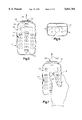
- FIG. 4 shows a perspective view of an alternative hand held portable dataform reader according to this invention.
- FIG. 5 shows a top view of the portable dataform reader of FIG. 4.
- FIG. 6 shows a front view of the housing for the portable data terminal of FIG. 4.
- FIG. 8 shows a cut away side view of the dataform reader of FIG. 1.
- FIG. 9 shows a cut away side view of the dataform reader of FIG. 4.
- FIG. 10 shows a diagrammatic top view of the reader module in accordance with this invention.
- FIGS. 11a-11d conceptually show the calculation of MTF.
- FIG. 12 shows a MTF plot for a preferred embodiment of the optic assembly according to this invention.
- FIG. 14 shows a diagrammatic representation of field flatness.
- FIG. 15 shows a diagrammatic representation of the optic assembly in accordance with this invention.
- FIGS. 18a and 18b show an alternative illuminator module in accordance with this invention.
- FIG. 20 shows a block diagram of the voice mail system according to the present invention.
- FIG. 21 shows a wireless headset in accordance with this invention.
- the portable dataform reader of this invention can have several housing configurations, two of which are generally shown in FIGS. 1-6. Like numerals are used to identify similar parts, wherein the housing shown in FIGS. 1-3 is generally a gun shaped reader 10 with a housing 12, forming an upper enclosure, and a handle portion 14 extending below the upper enclosure.
- the housing is constructed of a suitable impact resistant plastic that provides both durability and light weight.
- a trigger switch 16 is appropriately mounted and used to provide a signal to initiate a dataform reading session.
- a plurality of key switches 22 and a display screen 32 with an overlaying touch panel 44 are visible on the upper surface.
- An illumination module 28 is secured to the forward end of the housing 18 so that the noise effects and illumination loss associated with placing illuminators within the housing and behind a window are eliminated.
- the forward end of the housing 18 is shown in FIG. 3 without the illuminator module 28.
- a generally circular shaped aperture 17 is formed in the forward end 18 so that a dataform positioned to the front of the reader may be read by a reader module positioned in the forward end of the upper enclosure.
- the housing also includes four holes 19 for securing the illuminator module to the front of the housing 18 with screws.
- the terminal 10 shown in FIGS. 4-6 is generally a palm sized terminal configured to be held in the palm of the operators hand as shown in FIG. 7.
- a plurality of key switches on the upper surface 22 are positioned to be operated by the same hand holding the terminal.
- Also on the upper surface is a display screen 32 with an overlaying touch panel 44.
- the housing 12 is constructed of a suitable impact resistant plastic for both durability and light weight.
- a trigger switch 16 to initiate a dataform reading session is located at the center of the upper surface to enable activation by the operator's thumb.
- the illumination module 28 is secured to the forward end of the housing 18.
- the forward end 18, shown without the illumination module 28 in FIG. 6, includes a generally circular shaped aperture 17 so that a dataform positioned in the front of the terminal 20 may be read by a reader module positioned in the forward end of the terminal.
- FIGS. 8 and 9 show a cut away side view of the reader of FIGS. 1-6, it can be seen that a reader module 26 is positioned inside of the reader housing immediately behind the front surface 18.
- the camera housing 64 projects through the aperture 17 in the reader housing and aperture 36 in the illumination module.
- a seal (not shown) may be placed around the camera housing nose 64 to create a tight seal between the camera housing and the reader housing 12 to prevent dirt and moisture from entering the interior of the reader housing through the aperture 17.
- FIG. 10 shows a top view of the reader module 26.
- the module includes a board camera assembly (shown as a three board assembly) 62 with a two-dimensional array of photodetectors 60.
- the reader module 26 also includes an optic assembly 58 for focusing an image of the target area 66 onto the two dimensional array of photosensors 60.
- a camera housing 64 shrouds ambient light from the photosensor array 60 and positions the optic assembly 58 such that the photosensor array 60 is substantially at the image plane.
- the optic assembly 58 Based on the position between the optic assembly and the photosensor array, there exists a best focus position S2 in front of the optic assembly 58 at which an image of the object in the object field 66 will be sharpest on the sensor array 60. The image gradually degrades as the object is moved towards the near field cut off distance S1 and a far field cut off distance S3.
- the optic assembly 58 also has a field of view 68 which is wide enough to image large dataforms at the far field S3 and still provide a large image of a small dataform located at the near field S1.
- the optical assembly 58 has a working range from about 2.5" to at least 8.5" from the front surface of the optical assembly 86, with best focus distance being at 5.5".
- the preferred field of view corresponds to a target surface 5 inches long by 3.75 inches wide at 8.5" from lens surface 86.
- the sharpness of the image of an object at the best focus position S2 is determined by the resolution of the optic system.
- the resolution is the optics ability to transfer the contrast between dark and light areas of the object field to the image formed at the image plane.
- the ability of an optic system to transfer contrast is quantified by the through focus Modulation Transfer Function (MTF).
- MTF Through Focus Modulation Transfer Function
- FIGS. 11a to 11d show conceptually the optical performance measured by MTF.
- a plurality of black bars and white spaces of equal size are positioned in a target area and focused to an image by the optic system. If the optic system were perfect, the image would be identical. However, because the optic is not perfect, the image will have a loss of contrast, that is the dark areas will be a little lighter and the light areas a little darker.
- the darkness of an image area is measured by a grayscale value with a grayscale value of 0 being very light and a grayscale value of 255 being very dark. Referring to FIG.
- FIG. 11b shows a grayscale plot through an image formed by a high resolution optic. It can be seen that the actual grayscale plot 202 has a lower peak to trough amplitude than the perfect grayscale plot represented by dashed line 204.
- FIG. 11d shows a grayscale plot through an image formed by a lower resolution optic. It can be seen that the peak to trough amplitude of the actual grayscale plot 206 is much lower than the amplitude of the ideal plot represented by dashed line 204.
- MTF is the fraction of the actual grayscale amplitude plot divided by the ideal grayscale amplitude for a particular bar spacing. Therefore, a higher resolution optic has a higher MTF.
- FIG. 12 shows a through focus MTF plot for the preferred optic 58 for the extended working range reader.
- the peak to trough amplitude ratio at the image plane is 60% as shown by 208 for a bar space pattern of 50 line pairs per millimeter (50 bars and 50 corresponding spaces in a 1 mm wide area). It can be seen that the MTF decreases when measured at a small offset from the image plane. At 0.5 mm shift from the image plane, the MTF has degraded to 20%.
- the working range in the object field is determined by the amount of image plane shift that can occur before the MTF degrades to an undecodable level.
- the working range cut-off distance will correspond to the image plane shift that causes MTF to drop to 15% at 50 line pairs per millimeter.
- the above stated working range can be achieved by an optic having a through focus MTF (modulation transfer function) of at least 40% at 50 cycles at the best focus position and at least 15% at a+-0.5 mm focus shift from the image plane.
- MTF modulation transfer function
- MTF is related to the aperture, or the size of the bundle of light rays that is allowed to pass through the optical system by the following equation:
- the F# is the ratio of the effective focal length of the optic (that is the distance between the second principal axis and the image plane) divided by the diameter of the aperture.
- ⁇ is the wavelength of illumination. It can be seen that a larger F# optic, corresponding to a smaller aperture, will improve the MTF and correspondingly improve the working range.
- the line spacing used to measure MTF at the image plane must be chosen based on the resolution of the photosensor array.
- the preferred photo sensor array has about a 6.5 micron pixel spacing.
- the smallest dataform cell must be imaged onto 1.5 pixels for decoding. Therefore, the image of the smallest dataform cell width must be about 10 microns (1.5 ⁇ 6.5).
- a line spacing of 50 line pairs per millimeter corresponds to 10 micron line spacing. Therefore, 50 line pairs per millimeter line spacing should be used for determining MTF.
- FIG. 14 conceptually shows field flatness.
- the photosensor array 60 is flat.
- An ideal image plane would be flat corresponding to the photo sensor array.
- the actual image plane 212 is not flat.
- the curvature of the image plane causes the photo sensor array 60 to be offset by a distance 216 at certain portions of the image. This offset is equivalent to the image plane shift, discussed earlier, that degrades MTF.
- an aspherical lens surface on at least one surface of the optic assembly should be used.
- An alternative embodiment for improved field flatness includes a lens with a diffractive optical surface producing a diffractive coefficient which refracts light incident upon the lens as an emerging wave front which arrives at focus at the image plane. Constructive interference of the light rays produced by the diffractive optic form a substantially flat and distortion free image at the image plane. Diffractive optical surfaces allow a high degree of correction in a single optical element and also provide color correction of a broad band optical system. A diffractive system also reduces the need for multiple lens elements resulting in cost savings in terms of fabrication.
- surface 86 is aspherical having a magnitude and shape defined as an even asphere having a radius of curvature of 1.5298 mm, a conic constant of -0.019890, a 6th order aspheric deformation coefficient of 0.0096 mm, an 8th order coefficient of -0.0057, and a 10th order coefficient of 0.0023.
- the surface 88 is a spherical surface with a radius of curvature of 1.6004 mm.
- the aperture 90 measures 0.3606 mm and is positioned between the lenses 82 and 84 as shown to provide the optical assembly an F#13.
- the lens diameter is not critical to this invention.
- the optic assembly is used in a portable reader, it is desirable that the assembly be light weight and impact resistant.
- the optical material used for fabricating the lens element is plastic.
- a plastic optic will reduce the weight of an equivalent glass assembly by 60% and provide a system much more impact resistant.
- Another benefit of plastic optics is that the costs associated with grinding aspherical surfaces on glass optics is avoided.
- An aspherical surface is easily formed by injection molding a plastic optic. While the above optic provides the desired attributes of the invention, those skilled in the art are able to provide other optics with similar performance characteristics.
- the optic system must have a large F# (F#5.6 or greater).
- the photosensor array exposure period and illuminator system for the reader must provide for adequate exposure of the photosensor array.
- the exposure period must be 0.01 seconds or less, which is substantially less than current CCD readers. Therefore, the illumination system of this invention must provide adequate illumination to accommodate the large #F# and short exposure time.
- module 28 includes a lens array 24 and a printed circuit board assembly 40.
- the printed circuit board assembly 40 includes a plurality of surface mount LEDs 46 secured to a printed circuit board 54.
- Printed circuit board 54 includes printed conductors and power lead 72 operative for supplying power to the LEDs 46.
- a suitable surface mount LED is produced by the Marktech Corporation of Latham, N.Y., as Part No. MTSM735K-UR or MTSM745KA-UR. Each provides luminosity of 285 mcd over an illumination field of about 68°.
- the small footprint of the LED 46 provides for twelve to be placed in a row measuring less than 1.5".
- the printed circuit board assembly 54 includes 24 LED's 46 in two rows providing 6840 mcd of uniform illumination over a 68° field.
- each exposure lens cell 30 has an inner lens surface 42 and a focal point 80.
- the lens cell acts as a light directing element rather than an imaging element thereby avoiding hot spots in the target area and providing a highly uniform illumination.
- the 68° field of illumination from each LED 46 is gathered by each lens cell 30 and directed into a field corresponding to the optical system field of view which is smaller than 68°.
- This illuminator system is called a sub-focal-length illuminator. The intensity variation of illumination from this system is less than 20% across the target area.
- two targeting lens elements 34 positioned over two targeting LEDs 47 project two pencils of targeting illumination 107, forming hot spots, into the target area at angles corresponding to the optical systems field of view 68.
- the hot spots are visible to the operator and facilitate positioning of the portable dataform hand held reader so that the target dataform is within the field of view of the optical system.
- the lens array 24 forms the front surface of the illumination module protecting the printed circuit board assembly 40 from physical impact as well as from dirt, moisture and other harmful elements found in the environment. Therefore, the lens array 24 is preferably molded of an impact resistant acrylic or other suitable material that has a high illumination transmissivity and durability necessary for the environment in which a portable hand held dataform reader is operated. To further protect the printed circuit board assembly 40 from harmful elements in the environment, a conformal coating is applied to the board assembly 40 and the assembly is bonded into a cavity in the back of the lens array 24 with a cyanoacrylate, UV curing or structural adhesive.
- the lens array provides uniform illumination to the target area
- this invention can also optionally provide for a frosted or holographic diffuser placed in front of the lens array to further improve uniformity.
- FIG. 18a and 18b show the front and side view of alternative embodiment of an illumination module 28.
- the module includes a plurality of discrete LED assemblies 138 encased in the acrylic ring 136.
- a circular array of optics 140 is formed on the front of the ring. The optics direct the illumination into a field corresponding to the field of the view of the optic. The cross talk caused by the solid ring encasing the illuminators and optics provide for an even field of illumination.
- FIG. 19 shows a front view of a multiple source LED assembly.
- a plurality of LED dies 160 are molded into a single acrylic casing 162.
- the casing includes an optic surface 164 in front of each die to conform the field of illumination to the field of view of the optic.
- the close spacing of the dies 160 that can be achieved combined with cross talk provides an even field of illumination. Construction of this device may also be accomplished by bonding the LEDs to the back surface of the casing 162 with a cyanoacrylate adhesive that has the same index of refraction as the casing 162.
- the interior of the housing includes a plurality of printed circuit boards including decoder board 56 and control board 31.
- the board camera 62 is operably connected to the decoder board.
- the output signal from sensor array 60 is a non-gain corrected raw video voltage signal.
- the voltage, at particular time increments, represents the accumulated charge on individual pixels.
- the board camera assembly 62 includes circuitry for generating a clock signal operative for driving the readout of the sensor array 60, exposure control circuitry for adjusting the exposure time for each field, gain control circuitry operative adjusting the gain of the raw video signal and other circuitry operative for generating a composite video signal from the raw video signal.
- Typical board cameras only have two operational states, "off” and "read-out”.
- the off state corresponds to a complete power shut down of the board camera.
- the "read-out” state corresponds to continuous generation of a video signal.
- Such a device is not practical in a portable dataform reader because it has a power up latency time, that is the period of time required to generate a stable video signal when transitioning from the "off” state to the "read-out” state of over 1 second. Because a portable dataform reader must provide a sub-second user response time, the board camera must remain in the "read-out” state continually. However, when in the "read-out” state, the device consumes too much power and would drain the batteries of a typical portable product within an hour.
- the preferred board camera 62 of this invention may have three operational states, "off", “ready”, and “read-out”.
- the "off” state and the readout state correspond to equivalent states in a typical board camera.
- power remains on to those circuits that cause the long power up latency and power is not applied to circuits that have a shorter latency.
- power is not applied to circuitry that causes the clocking signal for sensor array readout.
- the video signal from the board camera is transferred to the decoder board 56.
- the decoder board 56 includes image processing circuitry operative to decode the dataform in the image area and transfer the decoded results to the control board 31, preferably through a serial interface. An appropriate decoder system is described in U.S.
- Decoder board 56 also controls the dataform reading session by controlling the operational states of the board camera and supplying exposure and targeting power to the illumination module on a mutually exclusive basis.
- the control board 31 or the trigger switch 16 can send a signal to the decoder board 56 to initiate a reading session.
- the device in addition to capturing the image of a dataform, can be used to photograph an object in the target area. For example, an operator can use the reader module to photograph a damaged product and also capture an image of a dataform associated with the damaged product.
- the decoder board will transfer a digital image, such as a bit map, of the image to the control board 31.
- the control board 31 includes a serial output port coupled to a connector on the housing operative to transfer the decoded data or image data to a remote terminal through a cable connection (not shown).
- the connector may be a traditional pin connector to which a mating connector is secured.
- the connector may be conductive contact surfaces 11 on the exterior of the housing 12 which align with mating contact surfaces when the dataform reader is placed in a docking station.
- An image compression algorithm useful to reduce the size of a digital image file is the two-dimensional wavelet transform as described in A 64 kb/s Video Code Using the 2-D Wavelet Transform by A. S. Lewis and G. Knowles, published in IEEE Computer Society Press, Order Number 2202.
- the HARC wavelet transform system available from Houston Advance Research Center in Houston Tex., can be used to compress the photographic image before it is transmitted with an image compression ratio of up to 400:1.
- the message control unit 98 will prompt the operator to identify the addressee.
- the prompt may take the form of an audible signal to the operator through the audio output circuit 100 (discussed later), or a display screen message.
- the message control unit 98 will add the address to the message and relay the message to the spread spectrum transceiver for broadcast to the addressee. It should be appreciated that the voice mail system could require operator identification of the addressee before or after input of the message.
- the message control unit 98 operates to receive data files representative of incoming voice mail messages and stores such messages in memory 96. Upon receipt of an incoming message, the control unit 98 notifies the operator of receipt through the audio output circuit 100, the display screen or a dedicated illuminator.
- control unit 98 Upon an operator prompt to output the voice mail message, the control unit 98 will retrieve the data file from memory. A decompression module will convert the data file to an analog signal and audio output circuitry, which may include a speaker or a port for a remote speaker or headset will output the message. The operator prompt to output the message may be through the keyboard 22, touch panel 44 or the voice input circuit 92.
- the voice mail unit of this invention can optionally store the message for later playback or erase the message. In conjunction with storage or erasure, the message may be forwarded or responded to.
- the control unit will prompt the operator to input the various permutations of these options. If the message is stored, the digital data file will remain in memory 96. If forwarded, the data file, or a copy, will be appropriately addressed and transmitted to the spread radio 33.
- the speaker 50 and the microphone 52 are preferably positioned so that the reader may be held along the side of the operators face like a telephone set for communication.
- the speaker and microphone are embodied in a wireless headset.
- the headset includes a headband 115 for holding the device on an operators head, a speaker 117 positioned near the operators ear and a microphone 119 positioned near the operators mouth.
- a micro-radio module and power source are located in a housing 121 attached to the headset.
- the reader includes a similar micro-radio embodied on board 35 for transcieving audio signals with the headset.
- the micro-radio operates on a narrow band modulation scheme wherein the band is aligned in a null of the frequency spectrum of the spread spectrum radio.
- the micro-radio can function as a wireless peripheral port so that the operator may print a dataform label without physically connecting the dataform reader to a printer.
- Printers or other peripheral devices with similar micro radio boards may be placed throughout the installation in which the terminal is operated.
- a hand shake sequence is initiated and a wireless link is established.
- Data from the terminal may be printed out on the peripheral device.
- the power source 48 provides for operation over an extended period of time without requiring recharging.
- the power source 48 could be any rechargeable cell
- the preferable power source is a plurality of Lithium Polymer flexible battery cells. Each flexible sheet is about 0.002" (2 mils) thick and appears to be a sheet of plastic. To construct such a cell, LiMn 2 O 4 is used as the cathode and carbon as the anode. Such a cell is available from Bellcore of Red Bank N.J.
- One advantage of the lithium polymer cells is that the flexible sheet form factor is such that the cells may be folded and placed in areas of the housing which are of inadequate space for traditional cylindrical cells. In FIG.
Abstract
Description
MTF=λ/F#
Claims (11)
Priority Applications (10)
| Application Number | Priority Date | Filing Date | Title |
|---|---|---|---|
| US08/494,435 US5811784A (en) | 1995-06-26 | 1995-06-26 | Extended working range dataform reader |
| US08/507,607 US5815200A (en) | 1994-07-26 | 1995-07-25 | Extended working range dataform reader with reduced power consumption |
| US08/544,618 US5702059A (en) | 1994-07-26 | 1995-10-18 | Extended working range dataform reader including fuzzy logic image control circuitry |
| US08/580,063 US5703349A (en) | 1995-06-26 | 1995-12-20 | Portable data collection device with two dimensional imaging assembly |
| US08/603,848 US6019286A (en) | 1995-06-26 | 1996-02-22 | Portable data collection device with dataform decoding and image capture capability |
| US08/606,619 US5783811A (en) | 1995-06-26 | 1996-02-26 | Portable data collection device with LED targeting and illumination assembly |
| PCT/US1996/010917 WO1997001828A1 (en) | 1995-06-26 | 1996-06-26 | Extended working range dataform reader |
| AU63411/96A AU6341196A (en) | 1995-06-26 | 1996-06-26 | Extended working range dataform reader |
| US08/698,428 US5811774A (en) | 1994-07-26 | 1996-08-15 | Extended working range dataform reader with reduced power consumption |
| US08/787,668 US5818028A (en) | 1995-06-26 | 1997-01-23 | Portable data collection device with two dimensional imaging assembly |
Applications Claiming Priority (1)
| Application Number | Priority Date | Filing Date | Title |
|---|---|---|---|
| US08/494,435 US5811784A (en) | 1995-06-26 | 1995-06-26 | Extended working range dataform reader |
Related Child Applications (5)
| Application Number | Title | Priority Date | Filing Date |
|---|---|---|---|
| US08/507,607 Continuation-In-Part US5815200A (en) | 1994-07-26 | 1995-07-25 | Extended working range dataform reader with reduced power consumption |
| US08/544,618 Continuation-In-Part US5702059A (en) | 1994-07-26 | 1995-10-18 | Extended working range dataform reader including fuzzy logic image control circuitry |
| US08/580,063 Continuation-In-Part US5703349A (en) | 1995-06-26 | 1995-12-20 | Portable data collection device with two dimensional imaging assembly |
| US08/606,619 Continuation-In-Part US5783811A (en) | 1995-06-26 | 1996-02-26 | Portable data collection device with LED targeting and illumination assembly |
| US08/787,668 Continuation-In-Part US5818028A (en) | 1995-06-26 | 1997-01-23 | Portable data collection device with two dimensional imaging assembly |
Publications (1)
| Publication Number | Publication Date |
|---|---|
| US5811784A true US5811784A (en) | 1998-09-22 |
Family
ID=23964463
Family Applications (1)
| Application Number | Title | Priority Date | Filing Date |
|---|---|---|---|
| US08/494,435 Expired - Lifetime US5811784A (en) | 1994-07-26 | 1995-06-26 | Extended working range dataform reader |
Country Status (3)
| Country | Link |
|---|---|
| US (1) | US5811784A (en) |
| AU (1) | AU6341196A (en) |
| WO (1) | WO1997001828A1 (en) |
Cited By (68)
| Publication number | Priority date | Publication date | Assignee | Title |
|---|---|---|---|---|
| WO2000016363A1 (en) * | 1998-09-11 | 2000-03-23 | Robotic Vision Systems Inc. | Symbology imaging and reading apparatus and method |
| WO2001026036A2 (en) * | 1999-10-04 | 2001-04-12 | Welch Allyn Data Collection, Inc. | Imaging module for optical reader |
| US6371374B1 (en) | 1998-07-08 | 2002-04-16 | Welch Allyn Data Collection, Inc. | Adjustable illumination system for a barcode scanner |
| US20020100804A1 (en) * | 1990-09-10 | 2002-08-01 | Sung Ho Byun | Hand-held compact ergonomic laser scanner with integrated scanner activation or data transmission switch in scanner housing |
| US20030019934A1 (en) * | 1998-07-08 | 2003-01-30 | Hand Held Products, Inc. | Optical reader aiming assembly comprising aperture |
| US6550679B2 (en) | 1998-07-08 | 2003-04-22 | Hand Held Products, Inc. | Image sensor mounting system |
| US20030089776A1 (en) * | 1999-10-04 | 2003-05-15 | Hand Held Products, Inc. | Optical reader comprising support post |
| US6607128B1 (en) | 1998-07-08 | 2003-08-19 | Welch Allyn Data Collection Inc. | Optical assembly for barcode scanner |
| US6659350B2 (en) | 2000-11-01 | 2003-12-09 | Hand Held Products | Adjustable illumination system for a barcode scanner |
| US20040000592A1 (en) * | 2002-02-20 | 2004-01-01 | Welch Allyn, Inc. | Adjustable illumination system for a barcode scanner |
| US6688004B2 (en) * | 2001-06-28 | 2004-02-10 | S-B Power Tool Company | Line-of-cut indicator for a cutting tool |
| US6811088B2 (en) * | 1993-05-28 | 2004-11-02 | Symbol Technologies, Inc. | Portable data collection system |
| US6830181B1 (en) * | 1998-02-09 | 2004-12-14 | Intermec Ip Corp. | Combined optical and radio frequency tag reader |
| US6832725B2 (en) | 1999-10-04 | 2004-12-21 | Hand Held Products, Inc. | Optical reader comprising multiple color illumination |
| US20050103865A1 (en) * | 2003-11-13 | 2005-05-19 | Metrologic Instruments, Inc. | Hand-supportable imaging-based bar code symbol reader having a multi-mode bar code symbol image processor dynamically reconfigurable in response to real-time image processing operations carried out on captured images |
| US20050145698A1 (en) * | 2003-12-02 | 2005-07-07 | Havens William H. | Method and apparatus for reading under sampled bar code symbols |
| US20050241929A1 (en) * | 2004-04-29 | 2005-11-03 | Auger Paul A | Tensioned touch panel and method of making same |
| US20050263599A1 (en) * | 2003-11-13 | 2005-12-01 | Metrologic Instruments, Inc. | Digital imaging-based bar code symbol reading system employing a multi-mode image-processing symbol reading subsystem that switches its modes of reading during a single bar code symbol reading cycle, and within each said mode of reading, automatically applies a different image-processing based bar code symbol reading methodology |
| US6974080B1 (en) | 2002-03-01 | 2005-12-13 | National Graphics, Inc. | Lenticular bar code image |
| US20060202038A1 (en) * | 2005-03-11 | 2006-09-14 | Ynjiun Wang | System and method to automatically focus an image reader |
| US20060202036A1 (en) * | 2005-03-11 | 2006-09-14 | Ynjiun Wang | Bar code reading device with global electronic shutter control |
| US20070090193A1 (en) * | 2005-10-24 | 2007-04-26 | Laurens Nunnink | Integrated illumination assembly for symbology reader |
| US20070095918A1 (en) * | 2005-01-10 | 2007-05-03 | Kricorissian Gregg R | Targeting system for a portable image reader |
| US20080006699A1 (en) * | 2006-07-05 | 2008-01-10 | Industrial Data Entry Automation Systems, Inc. | Optical symbol scanner and illuminator with powered socket |
| US7387253B1 (en) * | 1996-09-03 | 2008-06-17 | Hand Held Products, Inc. | Optical reader system comprising local host processor and optical reader |
| US7523863B2 (en) | 1999-06-07 | 2009-04-28 | Metrologic Instruments, Inc. | Hand-supportable LED-based planar illumination and imaging system |
| US7527202B2 (en) | 2000-06-07 | 2009-05-05 | Metrologic Instruments, Inc. | Hand-supportable planar linear illumination and imaging (PLIIM) based code symbol reading system |
| US7614563B1 (en) | 2005-12-29 | 2009-11-10 | Cognex Technology And Investment Corporation | System and method for providing diffuse illumination in a symbology reader |
| US7651028B2 (en) | 2000-11-24 | 2010-01-26 | Metrologic Instruments, Inc. | Intelligent system for automatically recognizing objects at a point of sale (POS) station by omni-directional imaging of the objects using a complex of coplanar illumination and imaging subsystems |
| US7654461B2 (en) | 2003-11-13 | 2010-02-02 | Metrologic Instruments, Inc, | Automatically-triggered digital video imaging based code symbol reading system employing illumination and imaging subsystems controlled in response to real-time image quality analysis |
| US20100025469A1 (en) * | 2003-10-24 | 2010-02-04 | Gerst Iii Carl W | Method and apparatus for providing omnidirectional lighting in a scanning device |
| US7661597B2 (en) | 2000-11-24 | 2010-02-16 | Metrologic Instruments, Inc. | Coplanar laser illumination and imaging subsystem employing spectral-mixing and despeckling of laser illumination |
| US7681799B2 (en) | 2003-11-13 | 2010-03-23 | Metrologic Instruments, Inc. | Method of reading code symbols using a digital image capturing and processing system employing a micro-computing platform with an event-driven multi-tier software architecture |
| US7686222B2 (en) | 2001-07-13 | 2010-03-30 | Hand Held Products, Inc. | Optical reader having a color imager |
| US7708205B2 (en) | 2003-11-13 | 2010-05-04 | Metrologic Instruments, Inc. | Digital image capture and processing system employing multi-layer software-based system architecture permitting modification and/or extension of system features and functions by way of third party code plug-ins |
| US7770799B2 (en) | 2005-06-03 | 2010-08-10 | Hand Held Products, Inc. | Optical reader having reduced specular reflection read failures |
| US7780089B2 (en) | 2005-06-03 | 2010-08-24 | Hand Held Products, Inc. | Digital picture taking optical reader having hybrid monochrome and color image sensor array |
| US7823783B2 (en) | 2003-10-24 | 2010-11-02 | Cognex Technology And Investment Corporation | Light pipe illumination system and method |
| US7823789B2 (en) | 2004-12-21 | 2010-11-02 | Cognex Technology And Investment Corporation | Low profile illumination for direct part mark readers |
| US7841533B2 (en) | 2003-11-13 | 2010-11-30 | Metrologic Instruments, Inc. | Method of capturing and processing digital images of an object within the field of view (FOV) of a hand-supportable digitial image capture and processing system |
| US7852519B2 (en) | 2007-02-05 | 2010-12-14 | Hand Held Products, Inc. | Dual-tasking decoder for improved symbol reading |
| US7874485B2 (en) | 2003-05-12 | 2011-01-25 | Hand Held Products, Inc. | Adaptive optical image reader |
| US8074887B2 (en) | 2002-06-04 | 2011-12-13 | Hand Held Products, Inc. | Optical reader having a plurality of imaging modules |
| US8286878B2 (en) | 2004-12-16 | 2012-10-16 | Cognex Technology And Investment Corporation | Hand held symbology reader illumination diffuser |
| US20120294011A1 (en) * | 2011-05-16 | 2012-11-22 | Shat-R-Shield, Inc. | Method for attaching an optical lens to a printed circuit board with electronic light source |
| US8479998B2 (en) | 2011-01-31 | 2013-07-09 | Hand Held Products, Inc. | Terminal having optical imaging assembly |
| US8561903B2 (en) | 2011-01-31 | 2013-10-22 | Hand Held Products, Inc. | System operative to adaptively select an image sensor for decodable indicia reading |
| US8587595B2 (en) | 2009-10-01 | 2013-11-19 | Hand Held Products, Inc. | Low power multi-core decoder system and method |
| US8600167B2 (en) | 2010-05-21 | 2013-12-03 | Hand Held Products, Inc. | System for capturing a document in an image signal |
| US8596542B2 (en) | 2002-06-04 | 2013-12-03 | Hand Held Products, Inc. | Apparatus operative for capture of image data |
| US8608071B2 (en) | 2011-10-17 | 2013-12-17 | Honeywell Scanning And Mobility | Optical indicia reading terminal with two image sensors |
| US8629926B2 (en) | 2011-11-04 | 2014-01-14 | Honeywell International, Inc. | Imaging apparatus comprising image sensor array having shared global shutter circuitry |
| US8628015B2 (en) | 2008-10-31 | 2014-01-14 | Hand Held Products, Inc. | Indicia reading terminal including frame quality evaluation processing |
| US8657200B2 (en) | 2011-06-20 | 2014-02-25 | Metrologic Instruments, Inc. | Indicia reading terminal with color frame processing |
| USD704711S1 (en) * | 2011-11-04 | 2014-05-13 | Datalogic Ip Tech S.R.L. | Portable terminal |
| US8978983B2 (en) | 2012-06-01 | 2015-03-17 | Honeywell International, Inc. | Indicia reading apparatus having sequential row exposure termination times |
| US8978981B2 (en) | 2012-06-27 | 2015-03-17 | Honeywell International Inc. | Imaging apparatus having imaging lens |
| US9047531B2 (en) | 2010-05-21 | 2015-06-02 | Hand Held Products, Inc. | Interactive user interface for capturing a document in an image signal |
| US9070031B2 (en) | 2003-10-24 | 2015-06-30 | Cognex Technology And Investment Llc | Integrated illumination assembly for symbology reader |
| US9251392B2 (en) | 2012-06-01 | 2016-02-02 | Honeywell International, Inc. | Indicia reading apparatus |
| US9292724B1 (en) | 2004-12-16 | 2016-03-22 | Cognex Corporation | Hand held symbology reader illumination diffuser with aimer optics |
| US20160180130A1 (en) * | 2014-12-23 | 2016-06-23 | Hand Held Products, Inc. | Mini-barcode reading module with flash memory management |
| US9465962B2 (en) | 2006-06-29 | 2016-10-11 | Cognex Corporation | Method and apparatus for verifying two dimensional mark quality |
| US9536124B1 (en) | 2003-10-24 | 2017-01-03 | Cognex Corporation | Integrated illumination assembly for symbology reader |
| US9552506B1 (en) * | 2004-12-23 | 2017-01-24 | Cognex Technology And Investment Llc | Method and apparatus for industrial identification mark verification |
| US9798910B2 (en) | 2004-12-22 | 2017-10-24 | Cognex Corporation | Mobile hand held machine vision method and apparatus using data from multiple images to perform processes |
| US10592715B2 (en) | 2007-11-13 | 2020-03-17 | Cognex Corporation | System and method for reading patterns using multiple image frames |
| US20220406304A1 (en) * | 2021-06-21 | 2022-12-22 | Kyndryl, Inc. | Intent driven voice interface |
Citations (74)
| Publication number | Priority date | Publication date | Assignee | Title |
|---|---|---|---|---|
| US4210802A (en) * | 1977-07-26 | 1980-07-01 | Nippondenso Co., Ltd. | Bar code scanner |
| US4409470A (en) * | 1982-01-25 | 1983-10-11 | Symbol Technologies, Inc. | Narrow-bodied, single-and twin-windowed portable laser scanning head for reading bar code symbols |
| JPS60129891A (en) * | 1983-12-19 | 1985-07-11 | Fujitsu Kiden Ltd | Information processing method using bar code symbol |
| US4542528A (en) * | 1981-04-09 | 1985-09-17 | Recognition Equipment Incorporated | OCR and bar code reader with optimized sensor |
| JPS60264383A (en) * | 1984-06-12 | 1985-12-27 | 日立化成工業株式会社 | Manufacture of non-oxide ceramic distributing board |
| JPS6367692A (en) * | 1986-09-09 | 1988-03-26 | Nippon Denso Co Ltd | Optical information reader |
| US4734566A (en) * | 1985-02-19 | 1988-03-29 | Nippondenso Co., Ltd. | Apparatus and method for recognizing optical information |
| JPS6383886A (en) * | 1986-09-29 | 1988-04-14 | Matsushita Electric Ind Co Ltd | Bar code detector |
| US4766300A (en) * | 1984-08-06 | 1988-08-23 | Norand Corporation | Instant portable bar code reader |
| US4835615A (en) * | 1986-01-21 | 1989-05-30 | Minolta Camera Kabushiki Kaisha | Image sensor with improved response characteristics |
| US4877949A (en) * | 1986-08-08 | 1989-10-31 | Norand Corporation | Hand-held instant bar code reader system with automated focus based on distance measurements |
| US4952966A (en) * | 1983-01-10 | 1990-08-28 | Minolta Camera Kabushiki Kaisha | Focus detecting device for use with cameras |
| US4962432A (en) * | 1988-04-30 | 1990-10-09 | Fuji Photo Film Co., Ltd. | Selective retrieval of data from microfilm images of different forms by reading a memory index form cord (bar code) recorded on each image frame |
| US4996413A (en) * | 1990-02-27 | 1991-02-26 | General Electric Company | Apparatus and method for reading data from an image detector |
| US5010580A (en) * | 1989-08-25 | 1991-04-23 | Hewlett-Packard Company | Method and apparatus for extracting information from forms |
| US5019699A (en) * | 1988-08-31 | 1991-05-28 | Norand Corporation | Hand-held optical character reader with means for instantaneously reading information from a predetermined area at an optical sensing area |
| US5025319A (en) * | 1988-07-12 | 1991-06-18 | Fuji Photo Film Co., Ltd. | Solid state image pickup device driving method utilizing an electronic shutter operation |
| JPH03198175A (en) * | 1989-12-27 | 1991-08-29 | Fujikura Ltd | Bar-code reader |
| US5080456A (en) * | 1990-02-26 | 1992-01-14 | Symbol Technologies, Inc. | Laser scanners with extended working range |
| US5081343A (en) * | 1981-12-28 | 1992-01-14 | Norand Corporation | Instant portable bar code reader |
| US5083150A (en) * | 1989-03-03 | 1992-01-21 | Olympus Optical Co., Ltd. | Automatic focusing apparatus |
| US5101269A (en) * | 1990-09-18 | 1992-03-31 | Eastman Kodak Company | Stereoscopic electronic slide and print viewer |
| US5128769A (en) * | 1989-07-18 | 1992-07-07 | Fuji Photo Film Co., Ltd. | Method and apparatus for controlling exposure of video camera |
| US5130520A (en) * | 1982-01-25 | 1992-07-14 | Symbol Technologies, Inc. | Narrow-bodied, single- and twin-windowed portable laser scanning head for reading bar code symbols |
| US5131053A (en) * | 1988-08-10 | 1992-07-14 | Caere Corporation | Optical character recognition method and apparatus |
| US5168149A (en) * | 1989-10-30 | 1992-12-01 | Symbol Technologies, Inc. | Scan pattern generators for bar code symbol readers |
| US5184005A (en) * | 1990-01-08 | 1993-02-02 | Nippondenso Co. Ltd. | Non-decoded type bar code reading apparatus |
| US5187356A (en) * | 1981-12-28 | 1993-02-16 | Norand Corporation | Instant portable bar code reader |
| US5200597A (en) * | 1991-02-07 | 1993-04-06 | Psc, Inc. | Digitally controlled system for scanning and reading bar codes |
| US5210398A (en) * | 1991-06-14 | 1993-05-11 | Symbol Technologies, Inc. | Optical scanner with extended depth of focus |
| US5235167A (en) * | 1988-10-21 | 1993-08-10 | Symbol Technologies, Inc. | Laser scanning system and scanning method for reading bar codes |
| US5237365A (en) * | 1990-10-15 | 1993-08-17 | Olympus Optical Co., Ltd. | Exposure control apparatus for camera with shake countermeasure |
| US5243666A (en) * | 1989-11-01 | 1993-09-07 | Olympus Optical Co., Ltd. | Static-image signal generation apparatus using fuzzy theory |
| US5245445A (en) * | 1991-03-22 | 1993-09-14 | Ricoh Company, Ltd. | Image processing apparatus |
| JPH05242287A (en) * | 1992-02-27 | 1993-09-21 | Olympus Optical Co Ltd | Color bar code recording and reproducing device |
| US5258604A (en) * | 1992-01-28 | 1993-11-02 | Psc, Inc. | Bar code scanner |
| US5262871A (en) * | 1989-11-13 | 1993-11-16 | Rutgers, The State University | Multiple resolution image sensor |
| US5272538A (en) * | 1987-11-04 | 1993-12-21 | Canon Kabushiki Kaisha | Exposure control device |
| US5276315A (en) * | 1992-05-14 | 1994-01-04 | United Parcel Service Of America, Inc. | Method and apparatus for processing low resolution images of degraded bar code symbols |
| US5278397A (en) * | 1991-07-25 | 1994-01-11 | Symbol Technologies, Inc. | Multi-resolution bar code reader |
| US5291009A (en) * | 1992-02-27 | 1994-03-01 | Roustaei Alexander R | Optical scanning head |
| US5293238A (en) * | 1991-06-24 | 1994-03-08 | Hitachi, Ltd. | Televison camera |
| US5296690A (en) * | 1991-03-28 | 1994-03-22 | Omniplanar, Inc. | System for locating and determining the orientation of bar codes in a two-dimensional image |
| US5308966A (en) * | 1986-08-08 | 1994-05-03 | Norand Corporation | Hand-held instant bar code reader having automatic focus control for operation over a range of distances |
| US5309243A (en) * | 1992-06-10 | 1994-05-03 | Eastman Kodak Company | Method and apparatus for extending the dynamic range of an electronic imaging system |
| US5308960A (en) * | 1992-05-26 | 1994-05-03 | United Parcel Service Of America, Inc. | Combined camera system |
| US5314631A (en) * | 1989-10-25 | 1994-05-24 | Fujitsu Limited | Stationary bar code reader which can be detected and separated into a hand-held bar code reader |
| US5315095A (en) * | 1993-02-18 | 1994-05-24 | Symbol Technologies, Inc. | Beam with extended confinement for scanning purposes |
| US5319181A (en) * | 1992-03-16 | 1994-06-07 | Symbol Technologies, Inc. | Method and apparatus for decoding two-dimensional bar code using CCD/CMD camera |
| JPH06162247A (en) * | 1992-11-25 | 1994-06-10 | Matsushita Electric Ind Co Ltd | Two-dimensional code read bar code reader |
| US5331143A (en) * | 1992-08-28 | 1994-07-19 | Symbol Technologies, Inc. | Optical scanner using an axicon and an aperture to aspherically form the scanning beam |
| US5332892A (en) * | 1991-07-25 | 1994-07-26 | Symbol Technologies, Inc. | Optical systems for bar code scanners |
| US5340973A (en) * | 1990-09-17 | 1994-08-23 | Metrologic Instruments, Inc. | Automatic laser scanning system and method of reading bar code symbols using same |
| US5345266A (en) * | 1989-09-23 | 1994-09-06 | Vlsi Vision Limited | Matrix array image sensor chip |
| US5349172A (en) * | 1992-02-27 | 1994-09-20 | Alex Roustaei | Optical scanning head |
| US5352884A (en) * | 1993-04-14 | 1994-10-04 | General Electric Corporation | Method and apparatus for providing offset for light detector |
| US5354977A (en) * | 1992-02-27 | 1994-10-11 | Alex Roustaei | Optical scanning head |
| US5359185A (en) * | 1992-05-11 | 1994-10-25 | Norand Corporation | Chromatic ranging method and apparatus for reading optically readable information over a substantial range of distances |
| US5386271A (en) * | 1991-08-30 | 1995-01-31 | Minolta Camera Kabushiki Kaisha | Centralized control system for an image forming apparatus which employs fuzzy logic to identify abnormal conditions |
| US5401949A (en) * | 1991-06-12 | 1995-03-28 | American Neurologix, Inc. | Fuzzy logic barcode reader |
| US5406063A (en) * | 1993-05-07 | 1995-04-11 | Telxon Corporation | Hand-held data scanner having adjustable keyboard panel |
| US5408084A (en) * | 1993-02-18 | 1995-04-18 | United Parcel Service Of America, Inc. | Method and apparatus for illumination and imaging of a surface using 2-D LED array |
| US5414251A (en) * | 1992-03-12 | 1995-05-09 | Norand Corporation | Reader for decoding two-dimensional optical information |
| US5418357A (en) * | 1992-06-22 | 1995-05-23 | Matsushita Electric Industrial Co., Ltd. | Bar-code reader permitting selective use of a whole or a part of an image sensor |
| US5420635A (en) * | 1991-08-30 | 1995-05-30 | Fuji Photo Film Co., Ltd. | Video camera, imaging method using video camera, method of operating video camera, image processing apparatus and method, and solid-state electronic imaging device |
| US5420943A (en) * | 1992-04-13 | 1995-05-30 | Mak; Stephen M. | Universal computer input device |
| US5448293A (en) * | 1991-04-24 | 1995-09-05 | Matsushita Electric Industrial Co., Ltd. | Television camera equipped with continuously-variable-speed electronic shutter function |
| US5468947A (en) * | 1986-08-08 | 1995-11-21 | Norand Corporation | Pocket size data capture unit with processor and shell modules |
| US5478997A (en) * | 1988-10-21 | 1995-12-26 | Symbol Technologies, Inc. | Symbol scanning system and method having adaptive pattern generation |
| US5484994A (en) * | 1993-10-18 | 1996-01-16 | Roustaei; Alexander | Optical scanning head with improved resolution |
| US5486688A (en) * | 1991-06-26 | 1996-01-23 | Asahi Kogaku Kogyo Kabushiki Kaisha | Non-scanning type optical reading apparatus having illuminating equalization filter |
| US5496992A (en) * | 1994-06-21 | 1996-03-05 | Lxe, Inc. | Dual trigger multiplexed data entry terminal |
| US5504316A (en) * | 1990-05-08 | 1996-04-02 | Symbol Technologies, Inc. | Laser scanning system and scanning method for reading 1-D and 2-D barcode symbols |
| US5559555A (en) * | 1993-06-17 | 1996-09-24 | Sony Corporation | Apparatus for performing exposure control pertaining to the luminance level of an object |
-
1995
- 1995-06-26 US US08/494,435 patent/US5811784A/en not_active Expired - Lifetime
-
1996
- 1996-06-26 AU AU63411/96A patent/AU6341196A/en not_active Abandoned
- 1996-06-26 WO PCT/US1996/010917 patent/WO1997001828A1/en active Application Filing
Patent Citations (75)
| Publication number | Priority date | Publication date | Assignee | Title |
|---|---|---|---|---|
| US4210802A (en) * | 1977-07-26 | 1980-07-01 | Nippondenso Co., Ltd. | Bar code scanner |
| US4542528A (en) * | 1981-04-09 | 1985-09-17 | Recognition Equipment Incorporated | OCR and bar code reader with optimized sensor |
| US5187356A (en) * | 1981-12-28 | 1993-02-16 | Norand Corporation | Instant portable bar code reader |
| US5081343A (en) * | 1981-12-28 | 1992-01-14 | Norand Corporation | Instant portable bar code reader |
| US4409470A (en) * | 1982-01-25 | 1983-10-11 | Symbol Technologies, Inc. | Narrow-bodied, single-and twin-windowed portable laser scanning head for reading bar code symbols |
| US5130520A (en) * | 1982-01-25 | 1992-07-14 | Symbol Technologies, Inc. | Narrow-bodied, single- and twin-windowed portable laser scanning head for reading bar code symbols |
| US4952966A (en) * | 1983-01-10 | 1990-08-28 | Minolta Camera Kabushiki Kaisha | Focus detecting device for use with cameras |
| JPS60129891A (en) * | 1983-12-19 | 1985-07-11 | Fujitsu Kiden Ltd | Information processing method using bar code symbol |
| JPS60264383A (en) * | 1984-06-12 | 1985-12-27 | 日立化成工業株式会社 | Manufacture of non-oxide ceramic distributing board |
| US4766300A (en) * | 1984-08-06 | 1988-08-23 | Norand Corporation | Instant portable bar code reader |
| US4734566A (en) * | 1985-02-19 | 1988-03-29 | Nippondenso Co., Ltd. | Apparatus and method for recognizing optical information |
| US4835615A (en) * | 1986-01-21 | 1989-05-30 | Minolta Camera Kabushiki Kaisha | Image sensor with improved response characteristics |
| US4877949A (en) * | 1986-08-08 | 1989-10-31 | Norand Corporation | Hand-held instant bar code reader system with automated focus based on distance measurements |
| US5308966A (en) * | 1986-08-08 | 1994-05-03 | Norand Corporation | Hand-held instant bar code reader having automatic focus control for operation over a range of distances |
| US5468947A (en) * | 1986-08-08 | 1995-11-21 | Norand Corporation | Pocket size data capture unit with processor and shell modules |
| JPS6367692A (en) * | 1986-09-09 | 1988-03-26 | Nippon Denso Co Ltd | Optical information reader |
| JPS6383886A (en) * | 1986-09-29 | 1988-04-14 | Matsushita Electric Ind Co Ltd | Bar code detector |
| US5272538A (en) * | 1987-11-04 | 1993-12-21 | Canon Kabushiki Kaisha | Exposure control device |
| US4962432A (en) * | 1988-04-30 | 1990-10-09 | Fuji Photo Film Co., Ltd. | Selective retrieval of data from microfilm images of different forms by reading a memory index form cord (bar code) recorded on each image frame |
| US5025319A (en) * | 1988-07-12 | 1991-06-18 | Fuji Photo Film Co., Ltd. | Solid state image pickup device driving method utilizing an electronic shutter operation |
| US5131053A (en) * | 1988-08-10 | 1992-07-14 | Caere Corporation | Optical character recognition method and apparatus |
| US5019699A (en) * | 1988-08-31 | 1991-05-28 | Norand Corporation | Hand-held optical character reader with means for instantaneously reading information from a predetermined area at an optical sensing area |
| US5478997A (en) * | 1988-10-21 | 1995-12-26 | Symbol Technologies, Inc. | Symbol scanning system and method having adaptive pattern generation |
| US5235167A (en) * | 1988-10-21 | 1993-08-10 | Symbol Technologies, Inc. | Laser scanning system and scanning method for reading bar codes |
| US5083150A (en) * | 1989-03-03 | 1992-01-21 | Olympus Optical Co., Ltd. | Automatic focusing apparatus |
| US5128769A (en) * | 1989-07-18 | 1992-07-07 | Fuji Photo Film Co., Ltd. | Method and apparatus for controlling exposure of video camera |
| US5010580A (en) * | 1989-08-25 | 1991-04-23 | Hewlett-Packard Company | Method and apparatus for extracting information from forms |
| US5345266A (en) * | 1989-09-23 | 1994-09-06 | Vlsi Vision Limited | Matrix array image sensor chip |
| US5314631A (en) * | 1989-10-25 | 1994-05-24 | Fujitsu Limited | Stationary bar code reader which can be detected and separated into a hand-held bar code reader |
| US5168149A (en) * | 1989-10-30 | 1992-12-01 | Symbol Technologies, Inc. | Scan pattern generators for bar code symbol readers |
| US5243666A (en) * | 1989-11-01 | 1993-09-07 | Olympus Optical Co., Ltd. | Static-image signal generation apparatus using fuzzy theory |
| US5262871A (en) * | 1989-11-13 | 1993-11-16 | Rutgers, The State University | Multiple resolution image sensor |
| JPH03198175A (en) * | 1989-12-27 | 1991-08-29 | Fujikura Ltd | Bar-code reader |
| US5184005A (en) * | 1990-01-08 | 1993-02-02 | Nippondenso Co. Ltd. | Non-decoded type bar code reading apparatus |
| US5080456A (en) * | 1990-02-26 | 1992-01-14 | Symbol Technologies, Inc. | Laser scanners with extended working range |
| US4996413A (en) * | 1990-02-27 | 1991-02-26 | General Electric Company | Apparatus and method for reading data from an image detector |
| US5504316A (en) * | 1990-05-08 | 1996-04-02 | Symbol Technologies, Inc. | Laser scanning system and scanning method for reading 1-D and 2-D barcode symbols |
| US5340973A (en) * | 1990-09-17 | 1994-08-23 | Metrologic Instruments, Inc. | Automatic laser scanning system and method of reading bar code symbols using same |
| US5101269A (en) * | 1990-09-18 | 1992-03-31 | Eastman Kodak Company | Stereoscopic electronic slide and print viewer |
| US5237365A (en) * | 1990-10-15 | 1993-08-17 | Olympus Optical Co., Ltd. | Exposure control apparatus for camera with shake countermeasure |
| US5200597A (en) * | 1991-02-07 | 1993-04-06 | Psc, Inc. | Digitally controlled system for scanning and reading bar codes |
| US5245445A (en) * | 1991-03-22 | 1993-09-14 | Ricoh Company, Ltd. | Image processing apparatus |
| US5296690A (en) * | 1991-03-28 | 1994-03-22 | Omniplanar, Inc. | System for locating and determining the orientation of bar codes in a two-dimensional image |
| US5448293A (en) * | 1991-04-24 | 1995-09-05 | Matsushita Electric Industrial Co., Ltd. | Television camera equipped with continuously-variable-speed electronic shutter function |
| US5401949A (en) * | 1991-06-12 | 1995-03-28 | American Neurologix, Inc. | Fuzzy logic barcode reader |
| US5210398A (en) * | 1991-06-14 | 1993-05-11 | Symbol Technologies, Inc. | Optical scanner with extended depth of focus |
| US5293238A (en) * | 1991-06-24 | 1994-03-08 | Hitachi, Ltd. | Televison camera |
| US5486688A (en) * | 1991-06-26 | 1996-01-23 | Asahi Kogaku Kogyo Kabushiki Kaisha | Non-scanning type optical reading apparatus having illuminating equalization filter |
| US5332892A (en) * | 1991-07-25 | 1994-07-26 | Symbol Technologies, Inc. | Optical systems for bar code scanners |
| US5278397A (en) * | 1991-07-25 | 1994-01-11 | Symbol Technologies, Inc. | Multi-resolution bar code reader |
| US5420635A (en) * | 1991-08-30 | 1995-05-30 | Fuji Photo Film Co., Ltd. | Video camera, imaging method using video camera, method of operating video camera, image processing apparatus and method, and solid-state electronic imaging device |
| US5386271A (en) * | 1991-08-30 | 1995-01-31 | Minolta Camera Kabushiki Kaisha | Centralized control system for an image forming apparatus which employs fuzzy logic to identify abnormal conditions |
| US5258604A (en) * | 1992-01-28 | 1993-11-02 | Psc, Inc. | Bar code scanner |
| US5291009A (en) * | 1992-02-27 | 1994-03-01 | Roustaei Alexander R | Optical scanning head |
| US5349172A (en) * | 1992-02-27 | 1994-09-20 | Alex Roustaei | Optical scanning head |
| US5354977A (en) * | 1992-02-27 | 1994-10-11 | Alex Roustaei | Optical scanning head |
| JPH05242287A (en) * | 1992-02-27 | 1993-09-21 | Olympus Optical Co Ltd | Color bar code recording and reproducing device |
| US5414251A (en) * | 1992-03-12 | 1995-05-09 | Norand Corporation | Reader for decoding two-dimensional optical information |
| US5319181A (en) * | 1992-03-16 | 1994-06-07 | Symbol Technologies, Inc. | Method and apparatus for decoding two-dimensional bar code using CCD/CMD camera |
| US5420943A (en) * | 1992-04-13 | 1995-05-30 | Mak; Stephen M. | Universal computer input device |
| US5359185A (en) * | 1992-05-11 | 1994-10-25 | Norand Corporation | Chromatic ranging method and apparatus for reading optically readable information over a substantial range of distances |
| US5468950A (en) * | 1992-05-11 | 1995-11-21 | Norand Corporation | Chromatic ranging method and apparatus for reading optically readable information over a substantial range of distances |
| US5276315A (en) * | 1992-05-14 | 1994-01-04 | United Parcel Service Of America, Inc. | Method and apparatus for processing low resolution images of degraded bar code symbols |
| US5308960A (en) * | 1992-05-26 | 1994-05-03 | United Parcel Service Of America, Inc. | Combined camera system |
| US5309243A (en) * | 1992-06-10 | 1994-05-03 | Eastman Kodak Company | Method and apparatus for extending the dynamic range of an electronic imaging system |
| US5418357A (en) * | 1992-06-22 | 1995-05-23 | Matsushita Electric Industrial Co., Ltd. | Bar-code reader permitting selective use of a whole or a part of an image sensor |
| US5331143A (en) * | 1992-08-28 | 1994-07-19 | Symbol Technologies, Inc. | Optical scanner using an axicon and an aperture to aspherically form the scanning beam |
| JPH06162247A (en) * | 1992-11-25 | 1994-06-10 | Matsushita Electric Ind Co Ltd | Two-dimensional code read bar code reader |
| US5408084A (en) * | 1993-02-18 | 1995-04-18 | United Parcel Service Of America, Inc. | Method and apparatus for illumination and imaging of a surface using 2-D LED array |
| US5315095A (en) * | 1993-02-18 | 1994-05-24 | Symbol Technologies, Inc. | Beam with extended confinement for scanning purposes |
| US5352884A (en) * | 1993-04-14 | 1994-10-04 | General Electric Corporation | Method and apparatus for providing offset for light detector |
| US5406063A (en) * | 1993-05-07 | 1995-04-11 | Telxon Corporation | Hand-held data scanner having adjustable keyboard panel |
| US5559555A (en) * | 1993-06-17 | 1996-09-24 | Sony Corporation | Apparatus for performing exposure control pertaining to the luminance level of an object |
| US5484994A (en) * | 1993-10-18 | 1996-01-16 | Roustaei; Alexander | Optical scanning head with improved resolution |
| US5496992A (en) * | 1994-06-21 | 1996-03-05 | Lxe, Inc. | Dual trigger multiplexed data entry terminal |
Non-Patent Citations (2)
| Title |
|---|
| PCT International Search Report date Nov. 7, 1996 (one page). * |
| PCT International Search Report dated Sep. 18, 1996 (two pages). * |
Cited By (246)
| Publication number | Priority date | Publication date | Assignee | Title |
|---|---|---|---|---|
| US20020100804A1 (en) * | 1990-09-10 | 2002-08-01 | Sung Ho Byun | Hand-held compact ergonomic laser scanner with integrated scanner activation or data transmission switch in scanner housing |
| US6811088B2 (en) * | 1993-05-28 | 2004-11-02 | Symbol Technologies, Inc. | Portable data collection system |
| US8397992B2 (en) | 1994-03-04 | 2013-03-19 | Hand Held Products, Inc. | Optical reader having image sensor for reading decodable indicia |
| US8602309B2 (en) | 1994-03-04 | 2013-12-10 | Hand Held Products, Inc. | Bar code reading device for reading 1D or 2D bar code symbols |
| US7387253B1 (en) * | 1996-09-03 | 2008-06-17 | Hand Held Products, Inc. | Optical reader system comprising local host processor and optical reader |
| US6830181B1 (en) * | 1998-02-09 | 2004-12-14 | Intermec Ip Corp. | Combined optical and radio frequency tag reader |
| US6371374B1 (en) | 1998-07-08 | 2002-04-16 | Welch Allyn Data Collection, Inc. | Adjustable illumination system for a barcode scanner |
| US6550679B2 (en) | 1998-07-08 | 2003-04-22 | Hand Held Products, Inc. | Image sensor mounting system |
| US6607128B1 (en) | 1998-07-08 | 2003-08-19 | Welch Allyn Data Collection Inc. | Optical assembly for barcode scanner |
| US20030019934A1 (en) * | 1998-07-08 | 2003-01-30 | Hand Held Products, Inc. | Optical reader aiming assembly comprising aperture |
| US7306155B2 (en) | 1998-07-08 | 2007-12-11 | Hand Held Products, Inc. | Image sensor assembly for optical reader |
| US20050011954A1 (en) * | 1998-07-08 | 2005-01-20 | Hennick Robert J. | Image sensor assembly for optical reader |
| US8096472B2 (en) | 1998-07-08 | 2012-01-17 | Hand Held Products, Inc. | Image sensor assembly for optical reader |
| US20080128511A1 (en) * | 1998-07-08 | 2008-06-05 | Schwartz Eric D | Image sensor assembly for optical reader |
| WO2000016363A1 (en) * | 1998-09-11 | 2000-03-23 | Robotic Vision Systems Inc. | Symbology imaging and reading apparatus and method |
| US7533821B2 (en) | 1999-06-07 | 2009-05-19 | Metrologic Instruments, Inc. | Hand-supportable planar laser illumination and imaging (PLIIM) device for producing a planar laser illumination beam (PLIB) coplanar with the field of view (FOV) of a linear image detection array |
| US7523863B2 (en) | 1999-06-07 | 2009-04-28 | Metrologic Instruments, Inc. | Hand-supportable LED-based planar illumination and imaging system |
| US7644866B2 (en) | 1999-06-07 | 2010-01-12 | Metrologic Instruments, Inc. | Hand-supportable code symbol reader employing coplanar laser illumination and linear imaging |
| US7621455B2 (en) | 1999-06-07 | 2009-11-24 | Metrologic Instruments, Inc. | Hand-supportable code symbol reader employing coplanar laser illumination and linear imaging |
| US20070152055A1 (en) * | 1999-10-04 | 2007-07-05 | Barber Charles P | Imaging module for optical reader |
| US8474722B2 (en) | 1999-10-04 | 2013-07-02 | Hand Held Products, Inc. | Image sensor based optical reader |
| US20030089776A1 (en) * | 1999-10-04 | 2003-05-15 | Hand Held Products, Inc. | Optical reader comprising support post |
| US7500614B2 (en) | 1999-10-04 | 2009-03-10 | Hand Held Products, Inc. | Imaging module for optical reader |
| US7533824B2 (en) | 1999-10-04 | 2009-05-19 | Hand Held Products, Inc. | Image sensor based optical reader |
| WO2001026036A3 (en) * | 1999-10-04 | 2002-01-10 | Welch Allyn Data Collection | Imaging module for optical reader |
| US6832725B2 (en) | 1999-10-04 | 2004-12-21 | Hand Held Products, Inc. | Optical reader comprising multiple color illumination |
| US7270274B2 (en) | 1999-10-04 | 2007-09-18 | Hand Held Products, Inc. | Imaging module comprising support post for optical reader |
| WO2001026036A2 (en) * | 1999-10-04 | 2001-04-12 | Welch Allyn Data Collection, Inc. | Imaging module for optical reader |
| US9076054B2 (en) | 1999-10-04 | 2015-07-07 | Hand Held Products, Inc. | Image sensor based optical reader |
| US7878403B2 (en) | 1999-10-04 | 2011-02-01 | Hand Held Products, Inc. | Image sensor based optical reader |
| US7527202B2 (en) | 2000-06-07 | 2009-05-05 | Metrologic Instruments, Inc. | Hand-supportable planar linear illumination and imaging (PLIIM) based code symbol reading system |
| US6659350B2 (en) | 2000-11-01 | 2003-12-09 | Hand Held Products | Adjustable illumination system for a barcode scanner |
| US7905413B2 (en) | 2000-11-24 | 2011-03-15 | Metrologic Instruments, Inc. | Digital image capturing and processing system employing a plurality of coplanar illumination and imaging subsystems for digitally imaging objects in a 3D imaging volume, and a globally-deployed object motion detection subsystem for automatically detecting and analyzing the motion of objects passing through said 3-D imaging volume |
| US7661595B2 (en) | 2000-11-24 | 2010-02-16 | Metrologic Instruments, Inc. | Digital image capturing and processing system employing a plurality of area-type illuminating and imaging stations projecting a plurality of coextensive area-type illumination and imaging zones into a 3D imaging volume, and controlling operations therewithin using |
| US7819326B2 (en) | 2000-11-24 | 2010-10-26 | Metrologic Instruments, Inc. | Network of digital image capturing systems installed at retail POS-based stations and serviced by a remote image processing server in communication therewith |
| US7815113B2 (en) | 2000-11-24 | 2010-10-19 | Metrologic Instruments, Inc. | Method of and system for returning a consumer product in a retail environment so as to prevent or reduce employee theft, as well as provide greater accountability for returned merchandise in retail store environments |
| US7806336B2 (en) | 2000-11-24 | 2010-10-05 | Metrologic Instruments, Inc. | Laser beam generation system employing a laser diode and high-frequency modulation circuitry mounted on a flexible circuit |
| US7806335B2 (en) | 2000-11-24 | 2010-10-05 | Metrologic Instruments, Inc. | Digital image capturing and processing system for automatically recognizing objects in a POS environment |
| US7793841B2 (en) | 2000-11-24 | 2010-09-14 | Metrologic Instruments, Inc. | Laser illumination beam generation system employing despeckling of the laser beam using high-frequency modulation of the laser diode current and optical multiplexing of the component laser beams |
| US7784695B2 (en) | 2000-11-24 | 2010-08-31 | Metrologic Instruments, Inc. | Planar laser illumination module (PLIM) employing high-frequency modulation (HFM) of the laser drive currents and optical multplexing of the output laser beams |
| US7775436B2 (en) | 2000-11-24 | 2010-08-17 | Metrologic Instruments, Inc. | Method of driving a plurality of visible and invisible LEDs so as to produce an illumination beam having a dynamically managed ratio of visible to invisible (IR) spectral energy/power during object illumination and imaging operations |
| US7770796B2 (en) | 2000-11-24 | 2010-08-10 | Metrologic Instruments, Inc. | Device for producing a laser beam of reduced coherency using high-frequency modulation of the laser diode current and optical multiplexing of the output laser beam |
| US7762465B2 (en) | 2000-11-24 | 2010-07-27 | Metrologic Instruments, Inc. | Device for optically multiplexing a laser beam |
| US7731091B2 (en) | 2000-11-24 | 2010-06-08 | Metrologic Instruments, Inc. | Digital image capturing and processing system employing automatic object detection and spectral-mixing based illumination techniques |
| US8172141B2 (en) | 2000-11-24 | 2012-05-08 | Metrologic Instruments, Inc. | Laser beam despeckling devices |
| US7673802B2 (en) | 2000-11-24 | 2010-03-09 | Metrologic Instruments, Inc. | Automatic POS-based digital image capturing and processing system employing a plurality of area-type illumination and imaging zones intersecting within the 3D imaging volume of the system |
| US7665665B2 (en) | 2000-11-24 | 2010-02-23 | Metrologic Instruments, Inc. | Digital illumination and imaging subsystem employing despeckling mechanism employing high-frequency modulation of laser diode drive current and optical beam multiplexing techniques |
| US8042740B2 (en) | 2000-11-24 | 2011-10-25 | Metrologic Instruments, Inc. | Method of reading bar code symbols on objects at a point-of-sale station by passing said objects through a complex of stationary coplanar illumination and imaging planes projected into a 3D imaging volume |
| US7878407B2 (en) | 2000-11-24 | 2011-02-01 | Metrologic Instruments, Inc. | POS-based digital image capturing and processing system employing automatic object motion detection and spectral-mixing based illumination techniques |
| US7661597B2 (en) | 2000-11-24 | 2010-02-16 | Metrologic Instruments, Inc. | Coplanar laser illumination and imaging subsystem employing spectral-mixing and despeckling of laser illumination |
| US7658330B2 (en) | 2000-11-24 | 2010-02-09 | Metrologic Instruments, Inc. | Automatic POS-based digital image capturing and processing system employing object motion controlled area-type illumination and imaging operations |
| US7651028B2 (en) | 2000-11-24 | 2010-01-26 | Metrologic Instruments, Inc. | Intelligent system for automatically recognizing objects at a point of sale (POS) station by omni-directional imaging of the objects using a complex of coplanar illumination and imaging subsystems |
| US6688004B2 (en) * | 2001-06-28 | 2004-02-10 | S-B Power Tool Company | Line-of-cut indicator for a cutting tool |
| US7686222B2 (en) | 2001-07-13 | 2010-03-30 | Hand Held Products, Inc. | Optical reader having a color imager |
| US8292180B2 (en) | 2001-07-13 | 2012-10-23 | Hand Held Products, Inc. | Optical reader having an imager |
| US8528818B2 (en) | 2001-07-13 | 2013-09-10 | Hand Held Products, Inc. | Optical reader having an imager |
| US20040000592A1 (en) * | 2002-02-20 | 2004-01-01 | Welch Allyn, Inc. | Adjustable illumination system for a barcode scanner |
| US6974080B1 (en) | 2002-03-01 | 2005-12-13 | National Graphics, Inc. | Lenticular bar code image |
| US8074887B2 (en) | 2002-06-04 | 2011-12-13 | Hand Held Products, Inc. | Optical reader having a plurality of imaging modules |
| US8596542B2 (en) | 2002-06-04 | 2013-12-03 | Hand Held Products, Inc. | Apparatus operative for capture of image data |
| US9224023B2 (en) | 2002-06-04 | 2015-12-29 | Hand Held Products, Inc. | Apparatus operative for capture of image data |
| US7874485B2 (en) | 2003-05-12 | 2011-01-25 | Hand Held Products, Inc. | Adaptive optical image reader |
| US8770483B2 (en) | 2003-10-24 | 2014-07-08 | Cognex Technology And Investment Corporation | Light pipe illumination system and method |
| US20100025469A1 (en) * | 2003-10-24 | 2010-02-04 | Gerst Iii Carl W | Method and apparatus for providing omnidirectional lighting in a scanning device |
| US9536124B1 (en) | 2003-10-24 | 2017-01-03 | Cognex Corporation | Integrated illumination assembly for symbology reader |
| US9329332B2 (en) | 2003-10-24 | 2016-05-03 | Cognex Corporation | Light pipe illumination system and method |
| US9298960B2 (en) | 2003-10-24 | 2016-03-29 | Cognex Corporation | Method and apparatus for providing omnidirectional lighting in a scanning device |
| US9070031B2 (en) | 2003-10-24 | 2015-06-30 | Cognex Technology And Investment Llc | Integrated illumination assembly for symbology reader |
| US8740078B2 (en) | 2003-10-24 | 2014-06-03 | Cognex Technology And Investment Corporation | Method and apparatus for providing omnidirectional lighting in a scanning device |
| US8342405B2 (en) | 2003-10-24 | 2013-01-01 | Cognex Technology And Investment Corporation | Light pipe illumination system and method |
| US8282000B2 (en) | 2003-10-24 | 2012-10-09 | Cognex Technology And Investment Corporation | Method and apparatus for providing omnidirectional lighting in a scanning device |
| US8061614B2 (en) | 2003-10-24 | 2011-11-22 | Cognex Technology And Investment Corporation | Light pipe illumination system and method |
| US8061613B2 (en) | 2003-10-24 | 2011-11-22 | Cognex Technology And Investment Corporation | Method and apparatus for providing omnidirectional lighting in a scanning device |
| US7823783B2 (en) | 2003-10-24 | 2010-11-02 | Cognex Technology And Investment Corporation | Light pipe illumination system and method |
| US20120168512A1 (en) * | 2003-11-13 | 2012-07-05 | Anatoly Kotlarsky | Optical code symbol reading system employing a led-driven optical-waveguide structure for illuminating a manually-actuated trigger switch integrated within a hand-supportable system housing |
| US20050103849A1 (en) * | 2003-11-13 | 2005-05-19 | Xiaoxun Zhu | Automatic hand-supportable image-based bar code symbol reader having image-processing based bar code reading subsystem employing simple decode image processing operations applied in an outwardly-directed manner referenced from the center of a captured narrow-area digital image of an object bearing a 1D bar code symbol |
| US7278575B2 (en) | 2003-11-13 | 2007-10-09 | Metrologic Instruments, Inc. | Hand-supportable image-based bar code symbol reader employing helically-sweeping feature-extraction analysis on a captured digital image of an object referenced from the center thereof |
| US7273180B2 (en) | 2003-11-13 | 2007-09-25 | Metrologic Instruments, Inc. | Hand-supportable imaging-based bar code symbol reader having a multi-mode bar code symbol image processor dynamically reconfigurable in response to real-time image processing operations carried out on captured images |
| US9785811B2 (en) | 2003-11-13 | 2017-10-10 | Metrologic Instruments, Inc. | Image capture and processing system supporting a multi-tier modular software architecture |
| US7325738B2 (en) | 2003-11-13 | 2008-02-05 | Metrologic Instruments, Inc. | Method of and system for determining the lower limit of decoding resolution in an imaging-based bar code symbol reader |
| US9355288B2 (en) | 2003-11-13 | 2016-05-31 | Metrologic Instruments, Inc. | Image capture and processing system supporting a multi-tier modular software architecture |
| US7270272B2 (en) | 2003-11-13 | 2007-09-18 | Metrologic Instruments, Inc. | Digital image-based bar code symbol reading system employing a multi-mode image-processing symbol reading subsystem |
| US7267282B2 (en) | 2003-11-13 | 2007-09-11 | Metrologic Instruments, Inc. | Hand-supportable imaging-based bar code symbol reader capable of exposing an automatically detected object to a field of narrow-band LED-based illumination only when substantially all rows of pixels in a CMOS image sensing array are in a state of integration |
| US7255279B2 (en) | 2003-11-13 | 2007-08-14 | Metrologic Instruments, Inc. | Hand-supportable digital imaging-based bar code reading system wherein, during each imaging cycle, a single frame of pixel data is automatically detected by a CMOS area-type image sensing array when substantially all rows of pixels therein are in a state of integration and have a common integration time, and then pixel data is transmitted from said CMOS area-type image sensing array into a FIFO buffer, and then mapped into memory for subsequent image processing |
| US7654461B2 (en) | 2003-11-13 | 2010-02-02 | Metrologic Instruments, Inc, | Automatically-triggered digital video imaging based code symbol reading system employing illumination and imaging subsystems controlled in response to real-time image quality analysis |
| US7284705B2 (en) | 2003-11-13 | 2007-10-23 | Metrologic Instruments, Inc. | Hand-supportable semi-automatic digital imaging-based bar code symbol reading system realized upon a multi-tier modular software platform |
| US7243847B2 (en) | 2003-11-13 | 2007-07-17 | Metrologic Instruments, Inc. | Digital imaging-based bar code symbol reader employing an LED-based illumination subsystem driven by an automatic light exposure measurement and illumination control subsystem |
| US7240844B2 (en) | 2003-11-13 | 2007-07-10 | Metrologic Instruments, Inc. | Hand-suportable imaging-based bar code symbol reader employing an automatic light exposure measurement and illumination control subsystem for measuring illumination exposure on CMOS image sensing array and controlling LED illumination array driver circuitry |
| US7237722B2 (en) | 2003-11-13 | 2007-07-03 | Metrologic Instruments, Inc. | Hand-supported imaging-based bar code symbol reader employing a multi-mode image-processing based bar code reading subsystem with modular image-processing architecture |
| US7225988B2 (en) | 2003-11-13 | 2007-06-05 | Metrologic Instruments, Inc. | Hand-supportable imaging-based bar code symbol reader employing a tri-mode led-based illumination subsystem |
| US7225989B2 (en) | 2003-11-13 | 2007-06-05 | Metrologic Instruments, Inc. | Method of performing auto-discrimination of 1D/2D bar code symbologies in a semi-automatic hand-supportable imaging-based bar code symbol reader having narrow-area and wide-area image capture modes of operation |
| US7681799B2 (en) | 2003-11-13 | 2010-03-23 | Metrologic Instruments, Inc. | Method of reading code symbols using a digital image capturing and processing system employing a micro-computing platform with an event-driven multi-tier software architecture |
| US7360706B2 (en) | 2003-11-13 | 2008-04-22 | Metrologic Instruments, Inc. | Hand-supportable imaging-based auto-discriminating 1D/2D bar code symbol reader employing a multi-mode image processing bar code symbol reading subsystem having a plurality of modes of operation which are dynamically reconfigurable in response to real-time image analysis |
| US7216810B2 (en) | 2003-11-13 | 2007-05-15 | Metrologic Instruments, Inc. | Hand-supportable multi-mode digital imaging-based bar code symbol reader employing an automatic illumination and exposure control subsystem that automatically controls the operation of a multi-mode led-based illumination subsystem so that detected objects are sufficiently illuminated and good quality digital images thereof are formed and detected |
| US7708205B2 (en) | 2003-11-13 | 2010-05-04 | Metrologic Instruments, Inc. | Digital image capture and processing system employing multi-layer software-based system architecture permitting modification and/or extension of system features and functions by way of third party code plug-ins |
| US7712666B2 (en) | 2003-11-13 | 2010-05-11 | Metrologic Instruments, Inc. | Automatically-triggered digital video-imaging based code symbol reading system supporting dynamically controlled object illumination and digital video-imaging operations |
| US7213762B2 (en) | 2003-11-13 | 2007-05-08 | Metrologic Instruments, Inc. | Hand-supportable imaging-based bar code symbol reader employing a CMOS-type image sensing array in combination with a band-pass optical filter subsystem, narrow-band illumination subsystem, and automatic light exposure measurement and illumination control subsystem |
| US7735737B2 (en) | 2003-11-13 | 2010-06-15 | Metrologic Instruments, Inc. | Automatically-triggered digital video-imaging based code symbol reading system supporting ambient illumination mode automatically selected by adaptive control process |
| US20050103861A1 (en) * | 2003-11-13 | 2005-05-19 | Metrologic Instruments, Inc. | Hand-supportable digital imaging-based bar code reading system wherein, during each imaging cycle, a single frame of pixel data is automatically detected by a CMOS area-type image sensing array when substantially all rows of pixels therein are in a state of integration and have a common integration time, and then pixel data is transmitted from said CMOS area-type image sensing array into a FIFO buffer, and then mapped into memory for subsequent image processing |
| US20050103865A1 (en) * | 2003-11-13 | 2005-05-19 | Metrologic Instruments, Inc. | Hand-supportable imaging-based bar code symbol reader having a multi-mode bar code symbol image processor dynamically reconfigurable in response to real-time image processing operations carried out on captured images |
| US9104930B2 (en) | 2003-11-13 | 2015-08-11 | Metrologic Instruments, Inc. | Code symbol reading system |
| US7770798B2 (en) | 2003-11-13 | 2010-08-10 | Metrologic Instruments, Inc. | Automatically-triggered digital video-imaging based code symbol reading system for use in a point-of-sale (POS) environment |
| US7188770B2 (en) | 2003-11-13 | 2007-03-13 | Metrologic Instruments, Inc. | Hand-supportable semi-automatic imaging-based bar code reading system wherein an led-based illumination subsystem automatically illuminates a detected target object in a narrow-area field of illumination, and illuminates the detected target object in a wide-area field of illumination upon manual activation of a trigger switch |
| US20050103846A1 (en) * | 2003-11-13 | 2005-05-19 | Metrologic Instruments, Inc. | Hand-supportable imaging-based bar code symbol reader employing a multi-mode illumination subsystem enabling narrow-area illumination for aiming at a target object and illuminating aligned 1D bar code symbols during the narrow-area image capture mode, and wide-area illumination for illuminating randomly-oriented 1D and 2D bar code symbols during the wide-area image capture mode |
| US7185817B2 (en) | 2003-11-13 | 2007-03-06 | Metrologic Instruments, Inc. | Hand-supportable digital imaging-based bar codes symbol reader employing multi-mode subsystems |
| US7789309B2 (en) | 2003-11-13 | 2010-09-07 | Metrologic Instruments, Inc. | Automatic digital video-imaging based code symbol reading system employing illumination and imaging subsystems controlled within a control loop maintained as long as a code symbol has not been successfully read and the object is detected in the field of view of the system |
| US7178733B2 (en) | 2003-11-13 | 2007-02-20 | Metrologic Instruments, Inc. | Hand-supportable imaging-based bar code symbol reader employing automatic object presence and range detection to control the generation of near-field and far-field wide-area illumination during bar code symbol imaging operations |
| US7128266B2 (en) | 2003-11-13 | 2006-10-31 | Metrologic Instruments. Inc. | Hand-supportable digital imaging-based bar code symbol reader supporting narrow-area and wide-area modes of illumination and image capture |
| US7815121B2 (en) | 2003-11-13 | 2010-10-19 | Metrologic Instruments, Inc. | Method of modifying and/or extending the standard features and functions of a digital image capture and processing system |
| US8844822B2 (en) | 2003-11-13 | 2014-09-30 | Metrologic Instruments, Inc. | Image capture and processing system supporting a multi-tier modular software architecture |
| US7086595B2 (en) | 2003-11-13 | 2006-08-08 | Metrologic Instruments, Inc. | Method of and apparatus for processing captured digital images of objects within a semi-automatic hand-supportable imaging-based bar code symbol reader so as to read 1d and/or 2d bar code symbols graphically represented therein |
| US7293714B2 (en) | 2003-11-13 | 2007-11-13 | Metrologic Instruments, Inc. | Hand-supportable digital imaging-based bar code symbol reading system automatically processing captured images along parallel virtual scan lines based on the maximum pixel height of the region of interest (ROI) |
| US20050103862A1 (en) * | 2003-11-13 | 2005-05-19 | Metrologic Instruments, Inc. | Hand-supportable imaging-based bar code symbol reader employing automatic object presence and range detection to control the generation of near-field and far-field wide-area illumination during bar code symbol imaging operations |
| US7841533B2 (en) | 2003-11-13 | 2010-11-30 | Metrologic Instruments, Inc. | Method of capturing and processing digital images of an object within the field of view (FOV) of a hand-supportable digitial image capture and processing system |
| US7845559B2 (en) | 2003-11-13 | 2010-12-07 | Metrologic Instruments, Inc. | Hand-supportable digital image capture and processing system employing visible targeting illumination beam projected from an array of visible light sources on the rear surface of a printed circuit (PC) board having a light transmission aperture, and reflected off multiple folding mirrors and projected through the light transmission aperture into a central portion of the field of view of said system |
| US7845563B2 (en) | 2003-11-13 | 2010-12-07 | Metrologic Instruments, Inc. | Digital image capture and processing system employing an illumination subassembly mounted about a light transmission aperture, and a field of view folding mirror disposed beneath the light transmission aperture |
| US7845561B2 (en) | 2003-11-13 | 2010-12-07 | Metrologic Instruments, Inc. | Digital image capture and processing system supporting a periodic snapshot mode of operation wherein during each image acquisition cycle, the rows of image detection elements in the image detection array are exposed simultaneously to illumination |
| US20050103847A1 (en) * | 2003-11-13 | 2005-05-19 | Metrologic Instruments, Inc. | Method of performing auto-discrimination of 1D/2D bar code symbologies in a semi-automatic hand-supportable imaging-based bar code symbol reader having narrow-area and wide-area image capture modes of operation |
| US7854384B2 (en) | 2003-11-13 | 2010-12-21 | Metrologic Instruments, Inc. | Digital image capture and processing engine employing optical waveguide technology for collecting and guiding LED-based illumination during object illumination and image capture modes of operation |
| US7861936B2 (en) | 2003-11-13 | 2011-01-04 | Metrologic Instruments, Inc. | digital image capturing and processing system allowing third-parties to extend the features and functions of said system, and modify the standard behavior thereof without permanently modifying the standard features and functions thereof |
| US20050263599A1 (en) * | 2003-11-13 | 2005-12-01 | Metrologic Instruments, Inc. | Digital imaging-based bar code symbol reading system employing a multi-mode image-processing symbol reading subsystem that switches its modes of reading during a single bar code symbol reading cycle, and within each said mode of reading, automatically applies a different image-processing based bar code symbol reading methodology |
| US20050103867A1 (en) * | 2003-11-13 | 2005-05-19 | Xiaoxun Zhu | Hand-supportable semi-automatic digital imaging-based bar code symbol reading system realized upon a multi-tier modular software platform |
| US20050103868A1 (en) * | 2003-11-13 | 2005-05-19 | Xiaoxum Zhu | Digital imaging-based bar code symbol driven portable data terminal system |
| US7900839B2 (en) | 2003-11-13 | 2011-03-08 | Metrologic Instruments, Inc. | Hand-supportable digital image capture and processing system having a printed circuit board with a light transmission aperture, through which the field of view (FOV) of the image detection array and visible targeting illumination beam are projected using a FOV-folding mirror |
| US20050116039A1 (en) * | 2003-11-13 | 2005-06-02 | Metrologic Instruments, Inc. | Hand-supportable image-based bar code symbol reader employing helically-sweeping feature-extraction analysis on a captured digital image of an object referenced from the center thereof |
| US8517271B2 (en) * | 2003-11-13 | 2013-08-27 | Metrologic Instruments, Inc. | Optical code symbol reading system employing a LED-driven optical-waveguide structure for illuminating a manually-actuated trigger switch integrated within a hand-supportable system housing |
| US8366005B2 (en) | 2003-11-13 | 2013-02-05 | Metrologic Instruments, Inc. | Hand-supportable digital image capture and processing system supporting a multi-tier modular software architecture |
| US7950583B2 (en) | 2003-11-13 | 2011-05-31 | Metrologic Instruments, Inc | Automatic digital video imaging based code symbol reading system employing an automatic object motion controlled illumination subsystem |
| US7967209B2 (en) | 2003-11-13 | 2011-06-28 | Metrologic Instruments, Inc. | Method of blocking a portion of illumination rays generated by a countertop-supported digital imaging system, and preventing illumination rays from striking the eyes of the system operator or nearby consumers during operation of said countertop-supported digital image capture and processing system installed at a retail point of sale (POS) station |
| US7980471B2 (en) | 2003-11-13 | 2011-07-19 | Metrologic Instruments, Inc. | Method of unlocking restricted extended classes of features and functionalities embodied within a digital image capture and processing system by reading feature/functionality-unlocking type code symbols |
| US7988053B2 (en) | 2003-11-13 | 2011-08-02 | Metrologic Instruments, Inc. | Digital image capture and processing system employing an image formation and detection subsystem having image formation optics providing a field of view (FOV) on an area-type image detection array, and a multi-mode illumination subsystem having near and far field LED-based illumination arrays for illuminating near and far field portions of said FOV |
| US7997489B2 (en) | 2003-11-13 | 2011-08-16 | Metrologic Instruments, Inc. | Countertop-based digital image capture and processing system having an illumination subsystem employing a single array of LEDs disposed behind an illumination focusing lens structure integrated within the imaging window, for generating a field of visible illumination highly confined below the field |
| US8479992B2 (en) | 2003-11-13 | 2013-07-09 | Metrologic Instruments, Inc. | Optical code symbol reading system employing an acoustic-waveguide structure for coupling sonic energy, produced from an electro-transducer, to sound wave ports formed in the system housing |
| US8011585B2 (en) | 2003-11-13 | 2011-09-06 | Metrologic Instruments, Inc. | Digital image capture and processing system employing a linear LED-based illumination array mounted behind an illumination-focusing lens component integrated within the imaging window of the system |
| US20050116044A1 (en) * | 2003-11-13 | 2005-06-02 | Metrologic Instruments, Inc. | Method of and apparatus for processing captured digital images of objects within a semi-automatic hand-supportable imaging-based bar code symbol reader so as to read 1D and/or 2D bar code symbols graphically represented therein |
| US8047438B2 (en) | 2003-11-13 | 2011-11-01 | Metrologic Instruments, Inc. | Digital image capture and processing system employing an image formation and detection subsystem having an area-type image detection array supporting periodic occurrance of snap-shot type image acquisition cycles at a high-repetition rate during object illumination |
| US8052057B2 (en) | 2003-11-13 | 2011-11-08 | Metrologic Instruments, Inc. | Method of programming the system configuration parameters of a digital image capture and processing system during the implementation of its communication interface with a host system without reading programming-type bar code symbols |
| US7428998B2 (en) | 2003-11-13 | 2008-09-30 | Metrologic Instruments, Inc. | Automatic hand-supportable image-based bar code symbol reader having image-processing based bar code reading subsystem employing simple decode image processing operations applied in an outwardly-directed manner referenced from the center of a captured narrow-area digital image of an object bearing a 1D bar code symbol |
| US7299986B2 (en) | 2003-11-13 | 2007-11-27 | Metrologic Instruments, Inc. | Digital imaging-based bar code symbol driven portable data terminal system |
| US20050103864A1 (en) * | 2003-11-13 | 2005-05-19 | Metrologic Instruments, Inc. | Hand-supportable digital imaging-based bar code symbol reading system employing a method of intelligently illuminating an object so as to generate a digital image thereof which is substantially free of noise caused by specular-type reflection of illumination off said object during illumination and imaging operations |
| US20050103851A1 (en) * | 2003-11-13 | 2005-05-19 | Metrologic Instruments, Inc. | Hand-supportable imaging-based bar code symbol reader employing a CMOS-type image sensor using global exposure techniques |
| US8087588B2 (en) | 2003-11-13 | 2012-01-03 | Metrologic Instruments, Inc. | Digital image capture and processing system having a single printed circuit (PC) board with a light transmission aperture, wherein a first linear array of visible light emitting diodes (LEDs) are mounted on the rear side of the PC board for producing a linear targeting illumination beam, and wherein a second linear array of visible LEDs are mounted on the front side of said PC board for producing a field of visible illumination within the field of view (FOV) of the system |
| US20050103863A1 (en) * | 2003-11-13 | 2005-05-19 | Metrologic Instruments, Inc. | Method of and system for determining the lower limit of decoding resolution in an imaging-based bar code symbol reader |
| US8100331B2 (en) | 2003-11-13 | 2012-01-24 | Metrologic Instruments, Inc. | Digital image capture and processing system having a printed circuit (PC) board with light transmission aperture, wherein first and second field of view (FOV) folding mirrors project the FOV of a digital image detection array on the rear surface of said PC board, through said light transmission aperture |
| US8132731B2 (en) | 2003-11-13 | 2012-03-13 | Metrologic Instruments, Inc. | Digital image capture and processing system having a printed circuit (PC) board with a light transmission aperture, wherein an image detection array is mounted on the rear side of said PC board, and a linear array of light emitting diodes (LEDS) is mounted on the front surface of said PC board, and aligned with an illumination-focusing lens structure integrated within said imaging window |
| US7922089B2 (en) | 2003-11-13 | 2011-04-12 | Metrologic Instruments, Inc. | Hand-supportable digital image capture and processing system employing automatic object presence detection to control automatic generation of a linear targeting illumination beam within the field of view (FOV), and manual trigger switching to initiate illumination |
| US8157174B2 (en) | 2003-11-13 | 2012-04-17 | Metrologic Instruments, Inc. | Digital image capture and processing system employing an image formation and detection system having an area-type image detection array supporting single snap-shot and periodic snap-shot modes of image acquisition during object illumination and imaging operations |
| US8157175B2 (en) | 2003-11-13 | 2012-04-17 | Metrologic Instruments, Inc. | Digital image capture and processing system supporting a presentation mode of system operation which employs a combination of video and snapshot modes of image detection array operation during a single cycle of system operation |
| US20050103857A1 (en) * | 2003-11-13 | 2005-05-19 | Metrologic Instruments, Inc. | Hand-supportable multi-mode imaging-based bar code symbol reader employing an automatic illumination and exposure control subsystem that automatically controls the operation of an LED-based multi-mode illumination subsystem so that detected objects are sufficiently illuminated and good quality digital images of detected objects are formed and detected by a multi-mode image formation and detection subsystem during illumination and imaging operations |
| US7281661B2 (en) | 2003-11-13 | 2007-10-16 | Metrologic Instruments, Inc. | Hand-supportable digital imaging-based bar code symbol reading system employing a method of intelligently illuminating an object so as to generate a digital image thereof which is substantially free of noise caused by specular-type reflection |
| US7320431B2 (en) | 2003-11-13 | 2008-01-22 | Metrologic Instruments, Inc. | Digital imaging-based bar code symbol reading system employing a multi-mode illumination subsystem with far-field and near field led-based illumination arrays |
| US8317105B2 (en) | 2003-11-13 | 2012-11-27 | Metrologic Instruments, Inc. | Optical scanning system having an extended programming mode and method of unlocking restricted extended classes of features and functionalities embodied therewithin |
| US7364081B2 (en) | 2003-12-02 | 2008-04-29 | Hand Held Products, Inc. | Method and apparatus for reading under sampled bar code symbols |
| US20050145698A1 (en) * | 2003-12-02 | 2005-07-07 | Havens William H. | Method and apparatus for reading under sampled bar code symbols |
| US20080083602A1 (en) * | 2004-04-29 | 2008-04-10 | Smart Technologies Inc. | Tensioned touch panel and method of making same |
| US7687736B2 (en) * | 2004-04-29 | 2010-03-30 | Smart Technologies Ulc | Tensioned touch panel and method of making same |
| US20050241929A1 (en) * | 2004-04-29 | 2005-11-03 | Auger Paul A | Tensioned touch panel and method of making same |
| US8067710B2 (en) | 2004-04-29 | 2011-11-29 | Smart Technologies Ulc | Tensioned touch panel and method of making same |
| US8286878B2 (en) | 2004-12-16 | 2012-10-16 | Cognex Technology And Investment Corporation | Hand held symbology reader illumination diffuser |
| US9361495B2 (en) | 2004-12-16 | 2016-06-07 | Cognex Technology And Investment Llc | Hand held symbology reader illumination diffuser |
| US9292724B1 (en) | 2004-12-16 | 2016-03-22 | Cognex Corporation | Hand held symbology reader illumination diffuser with aimer optics |
| US9495573B2 (en) | 2004-12-21 | 2016-11-15 | Cognex Technology And Investment Corporation | Low profile illumination for direct part mark readers |
| US8672227B2 (en) | 2004-12-21 | 2014-03-18 | Cognex Technology And Investment Corporation | Low profile illumination for direct part mark readers |
| US7823789B2 (en) | 2004-12-21 | 2010-11-02 | Cognex Technology And Investment Corporation | Low profile illumination for direct part mark readers |
| US9798910B2 (en) | 2004-12-22 | 2017-10-24 | Cognex Corporation | Mobile hand held machine vision method and apparatus using data from multiple images to perform processes |
| US9552506B1 (en) * | 2004-12-23 | 2017-01-24 | Cognex Technology And Investment Llc | Method and apparatus for industrial identification mark verification |
| US10061946B2 (en) | 2004-12-23 | 2018-08-28 | Cognex Technology And Investment Llc | Method and apparatus for industrial identification mark verification |
| US7377437B2 (en) * | 2005-01-10 | 2008-05-27 | Psion Teklogix Systems Inc. | Targeting system for a portable image reader |
| US20070095918A1 (en) * | 2005-01-10 | 2007-05-03 | Kricorissian Gregg R | Targeting system for a portable image reader |
| US9576169B2 (en) | 2005-03-11 | 2017-02-21 | Hand Held Products, Inc. | Image reader having image sensor array |
| US9305199B2 (en) | 2005-03-11 | 2016-04-05 | Hand Held Products, Inc. | Image reader having image sensor array |
| US11863897B2 (en) | 2005-03-11 | 2024-01-02 | Hand Held Products, Inc. | Image reader comprising CMOS based image sensor array |
| US10171767B2 (en) | 2005-03-11 | 2019-01-01 | Hand Held Products, Inc. | Image reader comprising CMOS based image sensor array |
| US7568628B2 (en) | 2005-03-11 | 2009-08-04 | Hand Held Products, Inc. | Bar code reading device with global electronic shutter control |
| US9578269B2 (en) | 2005-03-11 | 2017-02-21 | Hand Held Products, Inc. | Image reader comprising CMOS based image sensor array |
| US8146820B2 (en) | 2005-03-11 | 2012-04-03 | Hand Held Products, Inc. | Image reader having image sensor array |
| US11323650B2 (en) | 2005-03-11 | 2022-05-03 | Hand Held Products, Inc. | Image reader comprising CMOS based image sensor array |
| US8720781B2 (en) | 2005-03-11 | 2014-05-13 | Hand Held Products, Inc. | Image reader having image sensor array |
| US7611060B2 (en) | 2005-03-11 | 2009-11-03 | Hand Held Products, Inc. | System and method to automatically focus an image reader |
| US10721429B2 (en) | 2005-03-11 | 2020-07-21 | Hand Held Products, Inc. | Image reader comprising CMOS based image sensor array |
| US11323649B2 (en) | 2005-03-11 | 2022-05-03 | Hand Held Products, Inc. | Image reader comprising CMOS based image sensor array |
| US8733660B2 (en) | 2005-03-11 | 2014-05-27 | Hand Held Products, Inc. | Image reader comprising CMOS based image sensor array |
| US9465970B2 (en) | 2005-03-11 | 2016-10-11 | Hand Held Products, Inc. | Image reader comprising CMOS based image sensor array |
| US10735684B2 (en) | 2005-03-11 | 2020-08-04 | Hand Held Products, Inc. | Image reader comprising CMOS based image sensor array |
| US20060202038A1 (en) * | 2005-03-11 | 2006-09-14 | Ynjiun Wang | System and method to automatically focus an image reader |
| US11317050B2 (en) | 2005-03-11 | 2022-04-26 | Hand Held Products, Inc. | Image reader comprising CMOS based image sensor array |
| US7909257B2 (en) | 2005-03-11 | 2011-03-22 | Hand Held Products, Inc. | Apparatus having coordinated exposure period and illumination period |
| US8978985B2 (en) | 2005-03-11 | 2015-03-17 | Hand Held Products, Inc. | Image reader comprising CMOS based image sensor array |
| US20060202036A1 (en) * | 2005-03-11 | 2006-09-14 | Ynjiun Wang | Bar code reading device with global electronic shutter control |
| US10958863B2 (en) | 2005-03-11 | 2021-03-23 | Hand Held Products, Inc. | Image reader comprising CMOS based image sensor array |
| US11604933B2 (en) | 2005-06-03 | 2023-03-14 | Hand Held Products, Inc. | Apparatus having hybrid monochrome and color image sensor array |
| US8196839B2 (en) | 2005-06-03 | 2012-06-12 | Hand Held Products, Inc. | Optical reader having reduced specular reflection read failures |
| US11238252B2 (en) | 2005-06-03 | 2022-02-01 | Hand Held Products, Inc. | Apparatus having hybrid monochrome and color image sensor array |
| US11625550B2 (en) | 2005-06-03 | 2023-04-11 | Hand Held Products, Inc. | Apparatus having hybrid monochrome and color image sensor array |
| US9092654B2 (en) | 2005-06-03 | 2015-07-28 | Hand Held Products, Inc. | Digital picture taking optical reader having hybrid monochrome and color image sensor array |
| US10691907B2 (en) | 2005-06-03 | 2020-06-23 | Hand Held Products, Inc. | Apparatus having hybrid monochrome and color image sensor array |
| US10002272B2 (en) | 2005-06-03 | 2018-06-19 | Hand Held Products, Inc. | Apparatus having hybrid monochrome and color image sensor array |
| US9438867B2 (en) | 2005-06-03 | 2016-09-06 | Hand Held Products, Inc. | Digital picture taking optical reader having hybrid monochrome and color image sensor array |
| US9058527B2 (en) | 2005-06-03 | 2015-06-16 | Hand Held Products, Inc. | Apparatus having hybrid monochrome and color image sensor array |
| US8720785B2 (en) | 2005-06-03 | 2014-05-13 | Hand Held Products, Inc. | Apparatus having hybrid monochrome and color image sensor array |
| US11238251B2 (en) | 2005-06-03 | 2022-02-01 | Hand Held Products, Inc. | Apparatus having hybrid monochrome and color image sensor array |
| US8720784B2 (en) | 2005-06-03 | 2014-05-13 | Hand Held Products, Inc. | Digital picture taking optical reader having hybrid monochrome and color image sensor array |
| US9454686B2 (en) | 2005-06-03 | 2016-09-27 | Hand Held Products, Inc. | Apparatus having hybrid monochrome and color image sensor array |
| US7770799B2 (en) | 2005-06-03 | 2010-08-10 | Hand Held Products, Inc. | Optical reader having reduced specular reflection read failures |
| US7780089B2 (en) | 2005-06-03 | 2010-08-24 | Hand Held Products, Inc. | Digital picture taking optical reader having hybrid monochrome and color image sensor array |
| US10949634B2 (en) | 2005-06-03 | 2021-03-16 | Hand Held Products, Inc. | Apparatus having hybrid monochrome and color image sensor array |
| US8002188B2 (en) | 2005-06-03 | 2011-08-23 | Hand Held Products, Inc. | Method utilizing digital picture taking optical reader having hybrid monochrome and color image sensor |
| US7874487B2 (en) | 2005-10-24 | 2011-01-25 | Cognex Technology And Investment Corporation | Integrated illumination assembly for symbology reader |
| US20070090193A1 (en) * | 2005-10-24 | 2007-04-26 | Laurens Nunnink | Integrated illumination assembly for symbology reader |
| US9405951B2 (en) | 2005-10-24 | 2016-08-02 | Cognex Technology And Investment Llc | Integrated illumination assembly for symbology reader |
| US7614563B1 (en) | 2005-12-29 | 2009-11-10 | Cognex Technology And Investment Corporation | System and method for providing diffuse illumination in a symbology reader |
| US9465962B2 (en) | 2006-06-29 | 2016-10-11 | Cognex Corporation | Method and apparatus for verifying two dimensional mark quality |
| US7370801B2 (en) * | 2006-07-05 | 2008-05-13 | Industrial Data Entry Automation Systems Incorporated | Optical symbol scanner and illuminator with powered socket |
| US20080006699A1 (en) * | 2006-07-05 | 2008-01-10 | Industrial Data Entry Automation Systems, Inc. | Optical symbol scanner and illuminator with powered socket |
| US7852519B2 (en) | 2007-02-05 | 2010-12-14 | Hand Held Products, Inc. | Dual-tasking decoder for improved symbol reading |
| US10592715B2 (en) | 2007-11-13 | 2020-03-17 | Cognex Corporation | System and method for reading patterns using multiple image frames |
| US9323969B2 (en) | 2008-10-31 | 2016-04-26 | Hand Held Products, Inc. | Indicia reading terminal including frame quality evaluation processing |
| US8628015B2 (en) | 2008-10-31 | 2014-01-14 | Hand Held Products, Inc. | Indicia reading terminal including frame quality evaluation processing |
| US10296770B2 (en) | 2008-10-31 | 2019-05-21 | Hand Held Products, Inc. | Indicia reading terminal including frame quality evaluation processing |
| US9990520B2 (en) | 2008-10-31 | 2018-06-05 | Hand Held Products, Inc. | Indicia reading terminal including frame quality evaluation processing |
| US8587595B2 (en) | 2009-10-01 | 2013-11-19 | Hand Held Products, Inc. | Low power multi-core decoder system and method |
| US9659203B2 (en) | 2009-10-01 | 2017-05-23 | Hand Held Products, Inc. | Low power multi-core decoder system and method |
| US9384378B2 (en) | 2009-10-01 | 2016-07-05 | Hand Held Products, Inc. | Low power multi-core decoder system and method |
| US9092686B2 (en) | 2009-10-01 | 2015-07-28 | Hand Held Products, Inc. | Low power multi-core decoder system and method |
| US9047531B2 (en) | 2010-05-21 | 2015-06-02 | Hand Held Products, Inc. | Interactive user interface for capturing a document in an image signal |
| US9319548B2 (en) | 2010-05-21 | 2016-04-19 | Hand Held Products, Inc. | Interactive user interface for capturing a document in an image signal |
| US9521284B2 (en) | 2010-05-21 | 2016-12-13 | Hand Held Products, Inc. | Interactive user interface for capturing a document in an image signal |
| US9451132B2 (en) | 2010-05-21 | 2016-09-20 | Hand Held Products, Inc. | System for capturing a document in an image signal |
| US8600167B2 (en) | 2010-05-21 | 2013-12-03 | Hand Held Products, Inc. | System for capturing a document in an image signal |
| US8479998B2 (en) | 2011-01-31 | 2013-07-09 | Hand Held Products, Inc. | Terminal having optical imaging assembly |
| US8561903B2 (en) | 2011-01-31 | 2013-10-22 | Hand Held Products, Inc. | System operative to adaptively select an image sensor for decodable indicia reading |
| US20120294011A1 (en) * | 2011-05-16 | 2012-11-22 | Shat-R-Shield, Inc. | Method for attaching an optical lens to a printed circuit board with electronic light source |
| CN103733303A (en) * | 2011-05-16 | 2014-04-16 | 萨特-R-盾公司 | A method for attaching an optical lens to a printed circuit board with electronic light source |
| US8657200B2 (en) | 2011-06-20 | 2014-02-25 | Metrologic Instruments, Inc. | Indicia reading terminal with color frame processing |
| US8910875B2 (en) | 2011-06-20 | 2014-12-16 | Metrologic Instruments, Inc. | Indicia reading terminal with color frame processing |
| US8608071B2 (en) | 2011-10-17 | 2013-12-17 | Honeywell Scanning And Mobility | Optical indicia reading terminal with two image sensors |
| USD704711S1 (en) * | 2011-11-04 | 2014-05-13 | Datalogic Ip Tech S.R.L. | Portable terminal |
| US9407840B2 (en) | 2011-11-04 | 2016-08-02 | Honeywell International, Inc. | Imaging apparatus comprising image sensor array having shared global shutter circuitry |
| US8629926B2 (en) | 2011-11-04 | 2014-01-14 | Honeywell International, Inc. | Imaging apparatus comprising image sensor array having shared global shutter circuitry |
| US9066032B2 (en) | 2011-11-04 | 2015-06-23 | Honeywell International Inc. | Imaging apparatus comprising image sensor array having shared global shutter circuitry |
| US8978983B2 (en) | 2012-06-01 | 2015-03-17 | Honeywell International, Inc. | Indicia reading apparatus having sequential row exposure termination times |
| US9251392B2 (en) | 2012-06-01 | 2016-02-02 | Honeywell International, Inc. | Indicia reading apparatus |
| US8978981B2 (en) | 2012-06-27 | 2015-03-17 | Honeywell International Inc. | Imaging apparatus having imaging lens |
| US10049246B2 (en) * | 2014-12-23 | 2018-08-14 | Hand Held Products, Inc. | Mini-barcode reading module with flash memory management |
| US20160180130A1 (en) * | 2014-12-23 | 2016-06-23 | Hand Held Products, Inc. | Mini-barcode reading module with flash memory management |
| US20220406304A1 (en) * | 2021-06-21 | 2022-12-22 | Kyndryl, Inc. | Intent driven voice interface |
Also Published As
| Publication number | Publication date |
|---|---|
| AU6341196A (en) | 1997-01-30 |
| WO1997001828A1 (en) | 1997-01-16 |
Similar Documents
| Publication | Publication Date | Title |
|---|---|---|
| US5811784A (en) | Extended working range dataform reader | |
| US5815200A (en) | Extended working range dataform reader with reduced power consumption | |
| US5702059A (en) | Extended working range dataform reader including fuzzy logic image control circuitry | |
| EP1112522B1 (en) | Variable focus optical system | |
| CA2343326C (en) | Optical focusing device | |
| US5818028A (en) | Portable data collection device with two dimensional imaging assembly | |
| US5703349A (en) | Portable data collection device with two dimensional imaging assembly | |
| US6685092B2 (en) | Molded imager optical package and miniaturized linear sensor-based code reading engines | |
| AU2003297989B2 (en) | Image scanning device having a system for determining the distance to a target | |
| CA2457022C (en) | Image capture system and method using a common imaging array | |
| US6860428B1 (en) | Optical symbologies imager | |
| US5536924A (en) | Method and apparatus for matrix symbology imager | |
| MXPA97001398A (en) | Reader of data form of extended work regime with reduced power consumption | |
| US6338432B1 (en) | Optical pattern reading apparatus with movable optical unit | |
| AU2007203527B2 (en) | Image scanning device having a system for determining the distance to a target |
Legal Events
| Date | Code | Title | Description |
|---|---|---|---|
| AS | Assignment |
Owner name: METANETICS CORPORATION, FLORIDA Free format text: ASSIGNMENT OF ASSIGNORS INTEREST;ASSIGNORS:TAUSCH, J. MARK;WANG, P. YNJIUN;O'HAGAN, TIMOTHY P.;REEL/FRAME:008035/0844 Effective date: 19950914 |
|
| AS | Assignment |
Owner name: METANETICS CORPORATION, FLORIDA Free format text: ASSIGNMENT OF ASSIGNORS INTEREST;ASSIGNORS:TAUSCH, MARK J.;WANG, YNJIUN P.;O'HAGAN, TIMOTHY P.;REEL/FRAME:008171/0092 Effective date: 19950914 |
|
| STCF | Information on status: patent grant |
Free format text: PATENTED CASE |
|
| AS | Assignment |
Owner name: BANK OF NEW YORK, THE, NEW YORK Free format text: SECURITY INTEREST;ASSIGNOR:TELXON CORPORATION;REEL/FRAME:009817/0901 Effective date: 19990326 |
|
| AS | Assignment |
Owner name: BANK OF NEW YORK, THE, NEW YORK Free format text: SECURITY AGREEMENT;ASSIGNOR:META HOLDINGS CORPORATION;REEL/FRAME:010070/0749 Effective date: 19990326 |
|
| AS | Assignment |
Owner name: META HOLDING CORPORATION, OHIO Free format text: RELEASE BY SECURED PARTY;ASSIGNOR:BANK OF NEW YORK, AS AGENT, THE;REEL/FRAME:010216/0989 Effective date: 19990830 Owner name: META HOLDING CORPORATION, OHIO Free format text: RELEASE OF SECURITY INTEREST;ASSIGNOR:BANK ONE, NA;REEL/FRAME:010216/0935 Effective date: 19990830 Owner name: TELXON CORPORATION, OHIO Free format text: RELEASE BY SECURED PARTY;ASSIGNOR:THE BANK OF NEW YORK, AS AGENT;REEL/FRAME:010216/0776 Effective date: 19990830 |
|
| AS | Assignment |
Owner name: META HOLDING CORPORATION, TEXAS Free format text: ASSIGNMENT OF ASSIGNORS INTEREST;ASSIGNOR:METANETICS CORPORATION;REEL/FRAME:010710/0286 Effective date: 20000218 |
|
| FPAY | Fee payment |
Year of fee payment: 4 |
|
| AS | Assignment |
Owner name: SYMBOL TECHNOLOGIES, INC., NEW YORK Free format text: ASSIGNMENT OF ASSIGNORS INTEREST;ASSIGNOR:TELXON CORPORATION;REEL/FRAME:012795/0070 Effective date: 20020327 |
|
| AS | Assignment |
Owner name: TELXON CORPORATION, OHIO Free format text: MERGER;ASSIGNOR:META HOLDING CORPORATION;REEL/FRAME:015478/0168 Effective date: 20000218 Owner name: META HOLDING CORPORATION, FLORIDA Free format text: CHANGE OF NAME;ASSIGNOR:METANETICS CORPORATION;REEL/FRAME:015478/0575 Effective date: 19951102 |
|
| AS | Assignment |
Owner name: JPMORGAN CHASE BANK, N.A., NEW YORK Free format text: SECURITY INTEREST;ASSIGNOR:SYMBOL TECHNOLOGIES, INC.;REEL/FRAME:016116/0203 Effective date: 20041229 |
|
| FPAY | Fee payment |
Year of fee payment: 8 |
|
| FPAY | Fee payment |
Year of fee payment: 12 |
|
| AS | Assignment |
Owner name: SYMBOL TECHNOLOGIES, INC., NEW YORK Free format text: RELEASE BY SECURED PARTY;ASSIGNOR:JPMORGANCHASE BANK, N.A.;REEL/FRAME:025441/0228 Effective date: 20060901 |
|
| AS | Assignment |
Owner name: MORGAN STANLEY SENIOR FUNDING, INC. AS THE COLLATERAL AGENT, MARYLAND Free format text: SECURITY AGREEMENT;ASSIGNORS:ZIH CORP.;LASER BAND, LLC;ZEBRA ENTERPRISE SOLUTIONS CORP.;AND OTHERS;REEL/FRAME:034114/0270 Effective date: 20141027 Owner name: MORGAN STANLEY SENIOR FUNDING, INC. AS THE COLLATE Free format text: SECURITY AGREEMENT;ASSIGNORS:ZIH CORP.;LASER BAND, LLC;ZEBRA ENTERPRISE SOLUTIONS CORP.;AND OTHERS;REEL/FRAME:034114/0270 Effective date: 20141027 |
|
| AS | Assignment |
Owner name: SYMBOL TECHNOLOGIES, LLC, NEW YORK Free format text: CHANGE OF NAME;ASSIGNOR:SYMBOL TECHNOLOGIES, INC.;REEL/FRAME:036083/0640 Effective date: 20150410 |
|
| AS | Assignment |
Owner name: SYMBOL TECHNOLOGIES, INC., NEW YORK Free format text: RELEASE BY SECURED PARTY;ASSIGNOR:MORGAN STANLEY SENIOR FUNDING, INC.;REEL/FRAME:036371/0738 Effective date: 20150721 |