US5532880A - Laser beam expanders - Google Patents
Laser beam expanders Download PDFInfo
- Publication number
- US5532880A US5532880A US08/269,576 US26957694A US5532880A US 5532880 A US5532880 A US 5532880A US 26957694 A US26957694 A US 26957694A US 5532880 A US5532880 A US 5532880A
- Authority
- US
- United States
- Prior art keywords
- expander
- wavelength range
- lambda
- beam expander
- over
- Prior art date
- Legal status (The legal status is an assumption and is not a legal conclusion. Google has not performed a legal analysis and makes no representation as to the accuracy of the status listed.)
- Expired - Fee Related
Links
Images


Classifications
-
- G—PHYSICS
- G02—OPTICS
- G02B—OPTICAL ELEMENTS, SYSTEMS OR APPARATUS
- G02B1/00—Optical elements characterised by the material of which they are made; Optical coatings for optical elements
- G02B1/02—Optical elements characterised by the material of which they are made; Optical coatings for optical elements made of crystals, e.g. rock-salt, semi-conductors
-
- G—PHYSICS
- G02—OPTICS
- G02B—OPTICAL ELEMENTS, SYSTEMS OR APPARATUS
- G02B1/00—Optical elements characterised by the material of which they are made; Optical coatings for optical elements
- G02B1/06—Optical elements characterised by the material of which they are made; Optical coatings for optical elements made of fluids in transparent cells
Definitions
- This invention relates generally to laser beam expanders, and more particularly to high-performance laser beam expanders whose lens elements are made of crystalline and liquid optical materials.
- design forms had not been available for high-performance laser beam expanders capable of operating from the ultraviolet through the visible and into the near infared spectral regions.
- laser beam expanders (10) include lithium fluoride or barium fluoride or potassium bromide for the crystalline lens elements (11, 12, 14; 21, 22, 24; 31, 32, 34; 41, 42, 44; 51, 52, 54; 61, 62, 64), and include specified optical-quality liquids commercially available from R. L. Cargille Laboratories of Cedar Grove, N.J. are used for the liquid lens elements (13; 23; 33; 43; 53; 63).
- FIG. 1 is a pictorial illustration of a 5 X laser beam expander for a laser beam according to the present invention whose lens elements are made of lithium fluoride and Cargille 400513 liquid.
- FIG. 1A is an enlarged view of a portion of the 5 X laser beam expander enclosed within line 1A--1A of FIG. 1.
- FIG. 2 is a plot of normalized aperture height vs. optical path difference at five different wavelengths for the 5 X laser beam expander of FIG. 1.
- FIG. 3 is a plot of root-mean-square (RMS) wavefront error vs. wavelength over the wavelength range from 0.3 micron to 1.5 micron for the 5 X laser beam expander of FIG. 1.
- RMS root-mean-square
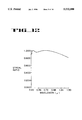
- FIG. 4 is a plot of Strehl ratio versus wavelength over the wavelength range from 0.3 micron to 1.5 micron for the 5 X laser beam expander of FIG. 1.
- FIG. 5 is a pictorial illustration of a 5 X laser beam expander for a laser beam according to the present invention whose lens elements are made of barium fluoride and Cargille 400513 liquid.
- FIG. 5A is an enlarged view of a portion of the 5 X laser beam expander enclosed within line 5A--5A of FIG. 5.
- FIG. 7 is a plot of RMS wavefront error vs. wavelength over the wavelength range from 0.3 micron to 2.5 micron for the 5 X laser beam expander of FIG. 5.
- FIG. 8 is a plot of Strehl ratio versus wavelength over the wavelength range from 0.3 micron to 2.5 micron for the 5 X laser beam expander of FIG. 5.
- FIG. 9 is a pictorial illustration of a 5 X laser beam expander according to the present invention whose lens elements are made of barium fluoride and Cargille 295990 liquid.
- FIG. 9A is an enlarged view of a portion of the 5 X laser beam expander enclosed within line 9A--9A of FIG. 9.
- FIG. 10 is a plot of normalized aperture height vs. optical path difference at five different wavelengths for the 5 X laser beam expander of FIG. 9.
- FIG. 11 is a plot of RMS wavefront error vs. wavelength over the wavelength range from 0.24 micron to 1.5 micron for the 5 X laser beam expander of FIG. 9.
- FIG. 12 is a plot of Strehl ratio versus wavelength over the wavelength range from 0.24 micron to 1.5 micron for the 5 X laser beam expander of FIG. 9.
- FIG. 13 is a pictorial illustration of a 4 X laser beam expander for a laser beam according to the present invention whose lens elements are made of barium fluoride and Cargille 295990 liquid.
- FIG. 13A is an enlarged view of a portion of the 4 X laser beam expander enclosed within line 13A--13A of FIG. 13.
- FIG. 14 is a plot of normalized aperture height vs. optical path difference at five different wavelengths for the 4 X laser beam expander of FIG. 13.
- FIG. 15 is a plot of RMS wavefront error vs. wavelength over the wavelength range from 0.24 micron to 2.0 micron for the 4 X laser beam expander of FIG. 13.
- FIG. 16 is a plot of Strehl ratio versus wavelength over the wavelength range from 0.24 micron to 2.0 micron for the 4 X laser beam expander of FIG. 13.
- FIG. 17 is a pictorial illustration of a 5 X laser beam expander for a laser beam according to the present invention whose elements are made of potassium bromide and Cargille 400513 liquid.
- FIG. 17A is an enlarged view of a portion of the 5 X laser beam expander enclosed within line 17A--17A of FIG. 17.
- FIG. 18 is a plot of normalized aperture height vs. optical path difference at five different wavelengths for the 5 X laser beam expander of FIG. 17.
- FIG. 19 is a plot of RMS wavefront error vs. wavelength over the wavelength range from 0.3 micron to 1.5 micron for the 5 X laser beam expander of FIG. 17.
- FIG. 20 is a plot of Strehl ratio versus wavelength over the wavelength range from 0.3 micron to 1.5 micron for the 5 X laser beam expander of FIG. 17.
- FIG. 21 is a pictorial illustration of a 5 X laser beam expander for a laser beam according to the present invention whose lens elements are made of potassium bromide and Cargille 295990 liquid.
- FIG. 21A is an enlarged view of a portion of the 5 X laser beam expander enclosed within line 21A--21A of FIG. 21.
- FIG. 22 is a plot of normalized aperture height vs. optical path difference at five different wavelengths for the 5 X laser beam expander of FIG. 21.
- FIG. 23 is a plot of RMS wavefront error vs. wavelength over the wavelength range from 0.24 micron to 2.5 micron for the 5 X laser beam expander of FIG. 21.
- FIG. 24 is a plot is a plot of Strehl ratio versus wavelength over the wavelength range from 0.24 micron to 2.5 micron for the 5 X laser beam expander of FIG. 21.
- a 5 X laser beam expander 10 according to the present invention is illustrated in which four lens elements 11, 12, 13, and 14 are coaxially disposed along an optic axis 9.
- the laser beam expander is an a focal lens system designed to expand a laser beam 7.
- the first lens element 11 is made of optical-quality lithium fluoride, a crystalline material, which is commercially obtainable from suppliers such as Harshaw Chemical Co. of Solon, Ohio.
- the second lens element 12 is likewise made of lithium fluoride.
- the third lens element 13 includes an optical liquid that is commercially available from R. L. Cargille Laboratories of Cedar Grove, N.J.
- the fourth lens element 14 is made of lithium fluoride.
- the lens elements 11, 12, 13, and 14 can be mounted in a conventional manner.
- An effective technique for containing the liquid lens element 13 between the rigid lens elements 12 and 14 made of lithium fluoride is described in copending U.S. patent application Ser. No. 08/014,596 filed on Feb. 8, 1993.
- FIG. 1A portions of the lens elements 12, 13, and 14 are shown in expanded view to illustrate the liquid lens element 13 contained between the crystalline (i.e., barium fluoride) lens elements 12 and 14.
- the Cargille liquid which forms the lens element 13 is a siloxane of proprietary composition, which is marketed under the designation as a laser liquid.
- This particular Cargille liquid can be uniquely identified according to the U.S. Mil-Spec system by code number 400513, which identifies a liquid whose nominal index of refraction at the wavelength of the sodium d spectral line (i.e., 0.58756 micron) at a temperature of 25° C. has the value 1.400 to the third decimal place, and whose Abbe number has the value 51.3 to the first decimal place.
- the optical properties of lithium fluoride (LiF) are well known. See, H. H. Li, Journal of Physics and Chemistry Reference Data, Volume 5, page 329 (1976).
- the laser beam expander illustrated in FIG. 1 expands an input laser beam from a diameter of 2 mm to a diameter of 10 mm (i.e., to produce a 5 X expansion) without requiring refocussing anywhere in the spectral range from 0.3 micron to 1.5 microns.
- the laser beam expander of FIG. 1 provides diffraction-limited performance over that spectral range, and chromatic aberration is virtually absent in the expanded beam.
- the 5 X laser beam expander of FIG. 1 has an optical prescription, which is specified in tabular format as follows:
- surfaces No. 1 and No. 2 are the left and right surfaces, respectively, of the lithium fluoride (LiF) lens element 11.
- a distance between Surface No. 2 and No. 3 in millimeters is listed showing the separation between the singlet lens and the lens set including Surface No. 3.
- air fills the space.
- the laser beam expander may function as well with vacuum or other relatively transparent environments contained within the spacing between Surface Nos. 2 or 3, with perhaps minor adjustments in spacing and lens shaping.
- Surface No. 3 is the left surface of the lithium fluoride lens element 12.
- the radius listed for each lens surface in Table I is the radius of curvature expressed in millimeters.
- the radius of curvature of a lens surface is positive if the center of curvature of the surface lies to the right of the surface, and negative if the center of curvature of the surface lies to the left of the surface.
- the thickness listed for each lens surface is the thickness expressed in millimeters of the lens element bounded on the left by the surface. The thickness of each lens element of the laser beam expander shown in FIG. 1 is measured along the optic axis 9.
- the index of refraction of an optical material varies with wavelength.
- the indices of refraction for the two different materials comprising the lens elements of the laser beam expander of FIG. 1 at five representative wavelengths in the range from 0.3 micron to 1.5 micron i.e., N 1 at 0.40000 micron; N 2 at 0.35000 micron; N 3 at 0.70000 micron; N 4 at 0.30000 micron; and N 5 at 1.50000 micron
- a graphical indication of performance of a lens system at a particular wavelength is provided by a plot of normalized aperture height as a function of optical path difference for that wavelength.
- plots of normalized aperture height as a function of optical path difference are shown for the five wavelengths for which the indices of refraction are specified in Table II. It may be seen from FIG. 2 that the maximum wavefront error for any one of the five plotted wavelengths is less than ⁇ /4.3 for the 5 X laser beam expander shown in FIG. 1.
- the optical path difference (OPD) error of an optical system at a particular wavelength is defined as the difference between the optical path length of a ray traced through a particular location in the entrance pupil of the system at a specified field angle and the optical path length of a reference ray, where the reference ray is usually taken to be the "chief ray” or "principal ray” traced through the center of the pupil at the specified field angle.
- the wavefront error of an optical system at a particular field angle is calculated as the statistical root-mean-square (RMS) of the optical path differences of a number of rays traced through the system at a single wavelength.
- RMS statistical root-mean-square
- FIG. 3 is a plot of root-mean-square (RMS) wavefront error versus wavelength for rays entering the 5 X laser beam expander of FIG. 1 parallel to the optic axis (i.e., at a field angle of zero) calculated over the wavelength range from 0.3 micron to 1.5 micron. It may be seen from FIG. 3 that the RMS wavefront error of the 5 X laser beam expander of FIG. 1 is less than ⁇ /14.7 between the wavelengths of 0.3 micron and 1.5 micron. The average RMS wavefront error over this wavelength range for the laser beam expander of FIG. 1 is ⁇ /28.7.
- RMS root-mean-square
- FIG. 4 is a plot of the Strehl ratio versus wavelength for rays entering the 5 X laser beam expander of FIG. 1 parallel to the optic axis 9 (i.e., at a field angle of zero) calculated over the wavelength range from 0.3 micron to 1.5 micron.
- the Strehl ratio is the ratio of the peak intensity in the diffraction point spread function of the optical system to that of a perfect (or abberation-free) diffraction-limited optical system.
- the average Strehl ratio is 0.94 over the wavelength range.
- FIG. 5 an alternative embodiment of a laser beam expander according to the present invention is illustrated in which the lens elements are made of barium fluoride and Cargille 400513 liquid.
- the laser beam expander of FIG. 5 expands an input laser beam 17 from a diameter of 2 mm to a diameter of 10 mm (i.e., to provide a 5 X expansion) with diffraction-limited performance without requiring refocussing anywhere in the spectral range from 0.3 micron to 2.5 micron.
- Optical-quality barium fluoride is obtainable from suppliers such as Harshaw Chemical Co. of Solon, Ohio. The properties of barium fluoride are well known. (See, H. H. Li, Journal of Physics and Chemistry Reference Data, Volume 9, page 161 (1980)).
- the 5 X laser beam expander of FIG. 5 comprises four lens elements 21, 22, 23, and 24, which are coaxially disposed along an optic axis.
- the first lens element 21 is made of barium fluoride (BaF).
- the second lens element 22 is likewise made of barium fluoride.
- the third lens element 23 includes Cargille 400513 liquid, and the fourth lens element 24 is made of barium fluoride.
- FIG. 5A portions of the lens elements 22, 23, and 24 are shown in expanded view to illustrate the liquid lens element 23 contained between the crystalline (i.e., barium fluoride) lens elements 22 and 24.
- the 5 X laser beam expander of FIG. 5 has an optical prescription, which is specified in tabular format as follows:
- the index of refraction of an optical material varies with wavelength.
- the indices of refraction for the two different materials comprising the lens elements of the laser beam expander of FIG. 5 at five representative wavelengths in the range from 0.3 micron to 2.500 micron i.e., N 1 at 0.40000 micron; N 2 at 0.35000 micron; N 3 at 0.70000 micron; N 4 at 0.30000 micron; and N 5 at 2.50000 micron
- performance of the 5 X laser beam expander of FIG. 5 is illustrated by plots of normalized aperture height as a function of optical path difference for the same five wavelengths for which the indices of refraction are specified in Table II. It may be seen from FIG. 6 that the maximum wavefront error of the 5 X laser beam expander of FIG. 5 for any one of the five plotted wavelengths is less than ⁇ /6.8.
- FIG. 7 is a plot of RMS wavefront error vs. wavelength for rays 17 entering the 5 X laser beam expander of FIG. 5 parallel to the optic axis 19 (i.e., at a field angle of zero) calculated over the wavelength range from 0.3 micron to 2.5 micron. It may be seen from FIG. 7 that the wavefront error of the 5 X laser beam expander of FIG. 5 is less than ⁇ /22.3 between the wavelengths of 0.3 micron and 2.5 micron. The average RMS wavefront error over this wavelength range for the laser beam expander of FIG. 5 is ⁇ /38.9.
- FIG. 8 is a plot of the Strehl ratio versus wavelength for rays entering the 5 X laser beam expander of FIG. 5 parallel to the optic axis 19 (i.e., at a field angle of zero) calculated over the wavelength range from 0.3 micron to 2.5 micron.
- the Strehl ratio is the ratio of the peak intensity in the diffraction point spread function of the optical system to that of a perfect (or abberation-free) diffraction-limited optical system.
- the average Strehl ratio is 0.97 over the wavelength range.
- FIG. 9 an alternate of a 5 X laser beam expander according to the present invention is illustrated whose lens elements include barium fluoride and Cargille 295990 liquid.
- the Cargille liquid is a perfluorocarbon (also known as perfluorochemical) of propriety composition that is commercially available from R. L. Cargille Laboratories of Cedar Grove, N.J.
- This particular Cargille liquid can be uniquely identified according to the U.S. Mil-Spec system by code number 295990, which identifies a liquid whose nominal index of refraction at the wavelength of the sodium d spectral line (i.e., 0.58756 micron) at a temperature of 25° C.
- Optical-quality barium fluoride is obtainable from suppliers such as Harshaw Chemical Co. of Solon, Ohio. The properties of barium fluoride are well known. (See, H. H. Li, Journal of Physics and Chemistry Reference Data, Volume 9, page 161 (1980)).
- the 5 X laser beam expander of FIG. 9 comprises four lens elements 31, 32, 33, and 34, which are coaxially disposed with respect to each other along an optic axis 29.
- the first lens element 31 is made of barium fluoride.
- the second lens element 32 is likewise made of barium fluoride.
- the third lens element 33 includes Cargille 295990 liquid; and the fourth lens element 34 is made of barium fluoride.
- FIG. 9A portions of the lens elements 32, 33, and 34 are shown in expanded view to illustrate the liquid lens element 33 contained between the crystalline (i.e., barium fluoride) lens elements 32 and 34.
- the 5 X laser beam expander of FIG. 9 has an optical prescription, which is specified in Table V as follows:
- performance of the 5 X laser beam expander of FIG. 9 is illustrated by plots of normalized aperture height as a function of optical path difference for the five wavelengths for which the indices of refraction are specified in Table VI. It may be seen from FIG. 10 that the maximum wavefront error of the 5 X laser beam expander shown in FIG. 9 for any one of the five plotted wavelengths is less than ⁇ /3.9.
- FIG. 12 is a plot of the Strehl ratio versus wavelength for rays entering the 5 X laser beam expander of FIG. 9 parallel to the optic axis (i.e., at a field angle of zero) calculated over the wavelength range from 0.24 micron to 1.5 micron.
- the Strehl ratio is the ratio of the peak intensity in the diffraction point spread function of the optical system to that of a perfect (or abberation-free) diffraction-limited optical system.
- the average Strehl ratio is 0.94 over the wavelength range.
- FIG. 13 an alternative embodiment of a laser beam expander according to the present invention is illustrated in which lens elements consist of barium fluoride and Cargille 295990 liquid.
- the laser beam expander of FIG. 13 provides a 4 X expansion with substantially diffraction-limited performance without requiring refocussing anywhere in the spectral range from 0.24 micron to 2.0 micron.
- Optical-quality barium fluoride is obtainable from suppliers such as Harshaw Chemical Co. of Solon, Ohio.
- the properties of barium fluoride are well known. (See, H. H. Li, Journal of Physics and Chemistry Reference Data, Volume 9, page 161 (1980)).
- the Cargille liquid is a perfluorocarbon (also known as perfluorochemical) of propriety composition that is commercially available from R. L. Cargille Laboratories of Cedar Grove, N.J. This particular Cargille liquid can be uniquely identified according to the U.S.
- Mil-Spec system by code number 295990 which identifies a liquid whose nominal index of refraction at the wavelength of the sodium d spectral line (i.e., 0.58756 micron) at a temperature of 25° C. has the value 1.295 to the third decimal place, and whose Abbe number has the value 99.0 to the first decimal place.
- the 4 X laser beam expander of FIG. 13 comprises four lens elements 41, 42, 43, and 44, which are coaxially disposed with respect to each other along an optic axis 39.
- the first lens element 41 is made of barium fluoride.
- the second lens element 42 is likewise made of barium fluoride.
- the third lens element 43 includes Cargille 295990 liquid, and the fourth lens element 44 is made of barium fluoride.
- FIG. 13A portions of the lens elements 42, 43, and 44 are shown in expanded view to illustrate the liquid lens element 43 contained between the crystalline (i.e., barium fluoride) lens elements 42 and 44.
- the 4 X laser beam expander of FIG. 13 has an optical prescription, which is specified in tabular format as follows:
- the index of refraction of an optical material varies with wavelength.
- the indices of refraction for the two different materials comprising the lens elements of the laser beam expander of FIG. 13 at five representative wavelengths in the range from 0.24 micron to 2.0 micron i.e., N 1 at 0.60000 micron; N 2 at 0.35000 micron; N 3 at 0.80000 micron; N 4 at 0.22000 micron; and N 5 at 2.00000 micron
- FIG. 15 is a plot of RMS wavefront error rs. wavelength for rays 37 entering the 4 X laser beam expander of FIG. 13 parallel to the optic axis 39 (i.e., at a field angle of zero) calculated over the wavelength range from 0.24 micron to 2.0 micron. It may be seen from FIG. 15 that the wavefront error of the 4 X laser beam expander of FIG. 13 is less than ⁇ /16.1 between the wavelengths of 0.24 micron and 2.0 micron. The average RMS wavefront error over this wavelength range for the laser beam expander of FIG. 13 is ⁇ /33.2.
- FIG. 16 is a plot of the Strehl ratio versus wavelength for rays 37 entering the 4 X laser beam expander of FIG. 13 parallel to the optic axis 39 (i. e., at a field angle of zero) calculated over the wavelength range from 0.24 micron to 2.0 micron.
- the Strehl ratio is the ratio of the peak intensity in the diffraction point spread function of the optical system to that of a perfect (or abberation-free) diffraction-limited optical system.
- the average Strehl ratio achieved for the lens is 0.95 over the wavelength range.
- FIG. 17 an alternate embodiment of a 5 X laser beam expander according to the present invention is illustrated whose lens elements include potassium bromide and Cargille 400513 liquid.
- Optical-quality potassium bromide is obtainable from suppliers such as Harshaw Chemical Co. of Solon, Ohio.
- the properties of potassium bromide are well known. (See, H. H. Li, Journal of Physics and Chemistry Reference Data, Volume 5, page 329 (1976)).
- the Cargille liquid of which the lens element 13 is made is a siloxane of proprietary composition which is commercially available from R. L. Cargille Laboratories of Cedar Grove, N.J. This particular Cargille liquid can be uniquely identified according to the U.S.
- FIG. 17A portions of the lens elements 52, 53, and 54 are shown in expanded view to illustrate the liquid lens element 53 contained between the crystalline (i.e., barium fluoride) lens elements 52 and 54.
- the 5 X laser beam expander of FIG. 17 has an optical prescription that is specified in Table IX as follows:
- the index of refraction of an optical material varies with wavelength.
- the indices of refraction for the two different materials comprising the lens elements of the laser beam expander of FIG. 17 at five representative wavelengths in the range from 0.3 micron to 1.5 micron i.e., N 1 at 0.40000 micron; N 2 at 0.35000 micron; N 3 at 0.70000 micron; N 4 at 0.30000 micron; and N 5 at 1.50000 micron
- performance of the 5 X laser beam expander of FIG. 17 is illustrated by plots of normalized aperture height as a function of optical path difference for the five wavelengths for which the indices of refraction are specified in Table X. It may be seen from FIG. 18 that the maximum wavefront error of the 5 X laser beam expander of FIG. 17 for any one of the five plotted wavelengths is less than ⁇ /3.6.
- FIG. 19 is a plot of RMS wavefront error versus wavelength for rays 47 entering the 5 X laser beam expander of FIG. 17 parallel to the optic axis 49 (i.e., at a field angle of zero) calculated over the wavelength range from 0.3 micron to 1.5 micron. It may be seen from FIG. 19 that the wavefront error of the 5 X laser beam expander of FIG. 17 is less than ⁇ /12.5 between the wavelengths of 0.3 micron and 1.5 micron. The average RMS wavefront error over this wavelength range for the laser beam expander of FIG. 17 is ⁇ /19.9.
- FIG. 20 is a plot of the Strehl ratio versus wavelength for rays 47 entering the 5 X laser beam expander of FIG. 17 parallel to the optic axis 49 (i.e., at a field angle of zero) calculated over the wavelength range from 0.3 micron to 1.5 micron.
- the Strehl ratio is the ratio of the peak intensity in the diffraction point spread function of the optical system to that of a perfect (or abberation-free) diffraction-limited optical system. An average Strehl ratio of 0.89 is obtained for the lens system.
- FIG. 21 an alternative embodiment of a laser beam expander according to the present invention is illustrated in which lens elements include potassium bromide and Cargille 295990 liquid.
- the laser beam expander of FIG. 21 expands an input laser beam from a diameter of 2 mm to a diameter of 10 mm (i.e., provides a 5 X expansion) with substantially diffraction-limited performance without requiring refocussing anywhere in the spectral range from 0.24 micron to 2.5 micron.
- the 5 X laser beam expander of FIG. 21 comprises four lens elements 61, 62, 63, and 64, which are coaxially disposed with respect to each other along an optic axis 59.
- the first lens element 61 is made of potassium bromide.
- the second lens element 62 is likewise made of potassium bromide.
- the third lens element 63 includes Cargille 295990 liquid, and the fourth lens element 64 is made of potassium bromide.
- FIG. 21A portions of the lens elements 62, 63, and 64 are shown in expanded view to illustrate the liquid lens element 63 contained between the crystalline (i.e., potassium bromide) lens elements 62 and 64.
- the 5 X laser beam expander of FIG. 21 has an optical prescription, which is specified in Table XI as follows:
- the index of refraction of an optical material varies with wavelength.
- the indices of refraction for the two different materials comprising the lens elements of the laser beam expander of FIG. 21 at five representative wavelengths in the range from 0.24 micron to 2.500 micron i.e., N 1 at 0.60000 micron; N 2 at 0.35000 micron; N 3 at 0.80000 micron; N 4 at 0.24000 micron; and N 5 at 2.00000 micron
- performance of the 5 X laser beam expander of FIG. 21 is illustrated by plots of normalized aperture height as a function of optical path difference for the same five wavelengths for which the indices of refraction are specified in Tables II, V and VIII. It may be seen from FIG. 22 that the maximum wavefront error of the 5 X laser beam expander of FIG. 21 for any one of the five plotted wavelengths is less than ⁇ /4.4.
- FIG. 23 is a plot of RMS wavefront error versus wavelength for rays 57 entering the 5 X laser beam expander of FIG. 21 parallel to the optic axis 59 (i.e., at a field angle of zero) calculated over the wavelength range from 0.24 micron to 2.5 micron. It may be seen from FIG. 23 that the wavefront error of the 5 X laser beam expander of FIG. 21 is less than ⁇ /9.6 between the wavelengths of 0.24 micron and 2.5 micron. The average RMS wavefront error over this wavelength range for the laser beam expander of FIG. 21 is ⁇ /18.8.
- FIG. 24 is a plot of the Strehl ratio versus wavelength for rays 57 entering the 5 X laser beam expander of FIG. 21 parallel to the optic axis 59 (i.e., at a field angle of zero) calculated over the wavelength range from 0.24 micron to 2.5 micron.
- the Strehl ratio is a ratio of peak amplitude in the focus of the optical system to the diffraction-limited amplitude. An average Strehl ratio of 0.88 is obtained for the lens set.
- the present invention provides a laser beam expander which may be readily configured for various laser beam expander applications by changing parametric values of the exemplary design forms.
- the singlet lens element in each embodiment may be replaced by a doublet lens whereby two lens elements may be used to provide greater negative power than that provided by the singlet lens element and in turn, permitting the design of an expander with a shortened length over the described embodiments, since the distance between the lens set and the doublet may be shortened.
Abstract
Description
              TABLE I
______________________________________
Surface
       Radius     Thickness
No.    (mm)       (mm)      N.sub.d
                                   V.sub.d
                                        Material
______________________________________
1      -28.185276 3.0000    1.392147
                                   97.29
                                        LiF
2      -125.314251
                  359.27367
3      -429.834471
                  3.0000    1.392147
                                   97.29
                                        LiF
4      -141.450738
                  0.5000    1.401102
                                   51.43
                                        400513
5      -310.063238
                  3.0000    1.392147
                                   97.29
                                        LiF
6      -126.569437
______________________________________
              TABLE II
______________________________________
Material
        N.sub.1  N.sub.2  N.sub.3
                                 N.sub.4
                                        N.sub.5
______________________________________
LiF     1.398939 1.402750 1.390218
                                 1.408705
                                        1.383156
400513  1.415243 1.423848 1.397626
                                 1.439067
                                        1.389945
______________________________________
              TABLE III
______________________________________
Surface
       Radius     Thickness
No.    (mm)       (mm)      N.sub.d
                                   V.sub.d
                                        Material
______________________________________
1      -26.769407 3.0000    1.474563
                                   81.77
                                        BaF
2      -96.847130 300.0000
3      -345.096979
                  3.0000    1.474563
                                   81.77
                                        BaF
4      -107.736357
                  0.5000    1.401102
                                   51.43
                                        400513
5      -489.432125
                  3.0000    1.474563
                                   81.77
                                        BaF
6      -139.750445
______________________________________
              TABLE IV
______________________________________
Material
        N.sub.1  N.sub.2  N.sub.3
                                 N.sub.4
                                        N.sub.5
______________________________________
BaF     1.484906 1.491071 1.471964
                                 1.501027
                                        1.463067
400513  1.415243 1.423848 1.397626
                                 1.439067
                                        1.379176
______________________________________
              TABLE V
______________________________________
Surface
       Radius     Thickness              Mate-
No.    (mm)       (mm)      N.sub.d
                                   V.sub.d
                                         rial
______________________________________
1      -26.108874 3.0000    1.474563
                                   81.77 BaF
2      -67.092838 350.057572
3      597.17992  3.0000    1.474563
                                   81.77 BaF
4      95.353178  1.5000    1.296386
                                   100.98
                                         295990
5      -56.372595 3.0000    1.474563
                                   81.77 BaF
6      -74.373237
______________________________________
              TABLE VI
______________________________________
Material
        N.sub.1  N.sub.2  N.sub.3
                                 N.sub.4
                                        N.sub.5
______________________________________
BaF     1.484906 1.501027 1.471964
                                 1.537843
                                        1.466312
295990  1.301480 1.309204 1.295028
                                 1.327036
                                        1.291078
______________________________________
              TABLE VII
______________________________________
Surface
       Radius     Thickness              Mate-
No.    (mm)       (mm)      N.sub.d
                                   V.sub.d
                                         rial
______________________________________
1      -31.088991 3.0000    1.474563
                                   81.77 BaF
2      -70.233397 350.008619
3      428.533305 3.0000    1.47563
                                   31.77 BaF
4      101.498781 1.5000     1.296386
                                   100.98
                                         295990
5      -59.943058 3.0000    1.47563
                                   81.77 BaF
6      -83.814257
______________________________________
              TABLE VIII
______________________________________
Material
        N.sub.1  N.sub.2  N.sub.3
                                 N.sub.4
                                        N.sub.5
______________________________________
BaF     1.474203 1.491071 1.470487
                                 1.537843
                                        1.464696
400513  1.296201 1.304444 1.294208
                                 1.327036
                                        1.289033
______________________________________
              TABLE IX
______________________________________
                   Thick-
Surface
       Radius      ness                  Mate-
No.    (mm)        (mm)     N.sub.d
                                   V.sub.d
                                         rial
______________________________________
1      -26.533554  3.0000   1.559948
                                   33.67 KBr
2      -89.955718  250.0000
3      -5534.615392
                   3.0000   1.559948
                                   33.67 KBr
4      343.863393  1.0000   1.401102
                                   51.43 400513
5      -76.841080  3.0000   1.559948
                                   33.67 KBr
6      -99.095829
______________________________________
              TABLE X
______________________________________
Material
        N.sub.1  N.sub.2  N.sub.3
                                 N.sub.4
                                        N.sub.5
______________________________________
KBr     1.591173 1.611685 1.552782
                                 1.648243
                                        1.539988
400513  1.415243 1.423848 1.397626
                                 1.439067
                                        1.389945
______________________________________
              TABLE XI
______________________________________
Surface
       Radius     Thickness              Mate-
No.    (mm)       (mm)      N.sub.d
                                   V.sub.d
                                         rial
______________________________________
1      -39.688685 3.0000    1.559948
                                   33.67 KBr
2      -193.458300
                  350.0000
3      -561.473238
                  3.0000    1.559948
                                   33.67 KBr
4      598.944093 1.5000    1.296386
                                   100.98
                                         295990
5      -147.782900
                  3.0000    1.559948
                                   33.67 KBr
6      -103.989822
______________________________________
              TABLE XII
______________________________________
Material
        N.sub.1  N.sub.2  N.sub.3
                                 N.sub.4
                                        N.sub.5
______________________________________
KBr     1.558935 1.611685 1.548894
                                 1.757484
                                        1.538328
400513  1.296201 1.304444 1.294208
                                 1.320380
                                        1.289033
______________________________________
Claims (45)
Priority Applications (1)
| Application Number | Priority Date | Filing Date | Title |
|---|---|---|---|
| US08/269,576 US5532880A (en) | 1994-07-01 | 1994-07-01 | Laser beam expanders |
Applications Claiming Priority (1)
| Application Number | Priority Date | Filing Date | Title |
|---|---|---|---|
| US08/269,576 US5532880A (en) | 1994-07-01 | 1994-07-01 | Laser beam expanders |
Publications (1)
| Publication Number | Publication Date |
|---|---|
| US5532880A true US5532880A (en) | 1996-07-02 |
Family
ID=23027838
Family Applications (1)
| Application Number | Title | Priority Date | Filing Date |
|---|---|---|---|
| US08/269,576 Expired - Fee Related US5532880A (en) | 1994-07-01 | 1994-07-01 | Laser beam expanders |
Country Status (1)
| Country | Link |
|---|---|
| US (1) | US5532880A (en) |
Cited By (19)
| Publication number | Priority date | Publication date | Assignee | Title |
|---|---|---|---|---|
| US6404560B1 (en) * | 1999-07-28 | 2002-06-11 | Nikon Corporation | Pressure proof optical apparatus |
| US6421365B1 (en) | 1999-11-18 | 2002-07-16 | Lambda Physik Ag | Narrow band excimer or molecular fluorine laser having an output coupling interferometer |
| US6522681B1 (en) | 1999-04-26 | 2003-02-18 | Lambda Physik Ag | Laser for the generation of narrow band radiation |
| US6553050B1 (en) | 1999-11-18 | 2003-04-22 | Lambda Physik Ag | Narrow band excimer or molecular fluorine laser having an output coupling interferometer |
| US6577665B2 (en) | 1999-04-07 | 2003-06-10 | Lambda Physik Ag | Molecular fluorine laser |
| US6603788B1 (en) | 1999-11-23 | 2003-08-05 | Lambda Physik Ag | Resonator for single line selection |
| US6631032B2 (en) | 2000-12-22 | 2003-10-07 | The Regents Of The University Of California | Renewable liquid reflection grating |
| US20030214729A1 (en) * | 2002-04-19 | 2003-11-20 | Wiese Gary E. | Refractive multispectral objective lens system and methods of selecting optical materials therefor |
| US6661558B2 (en) | 2000-12-22 | 2003-12-09 | The Regents Of The University Of California | Renewable liquid reflecting zone plate |
| US6764187B2 (en) | 2000-12-22 | 2004-07-20 | The Regents Of The University Of California | Universally oriented renewable liquid mirror |
| US6795473B1 (en) | 1999-06-23 | 2004-09-21 | Lambda Physik Ag | Narrow band excimer laser with a prism-grating as line-narrowing optical element |
| US20060119750A1 (en) * | 2004-10-19 | 2006-06-08 | Carl Zeiss Smt Ag | Optical system for ultraviolet light |
| US20110051229A1 (en) * | 2009-08-25 | 2011-03-03 | StingRay Optics, LLC | Achromatic visible to far infrared objective lens |
| US20110228384A1 (en) * | 2008-08-15 | 2011-09-22 | Vincent Andrei Handerek | Fluidic lens |
| CN103185964A (en) * | 2011-12-30 | 2013-07-03 | 中国科学院安徽光学精密机械研究所 | Ultraviolet multi-wavelength achromatic beam expander lens device |
| CN104682184A (en) * | 2015-03-16 | 2015-06-03 | 中国工程物理研究院激光聚变研究中心 | Longitudinal local beam-expanding triple frequency laser terminal optical system |
| US9769902B1 (en) | 2011-05-09 | 2017-09-19 | The United States Of America As Represented By Secretary Of The Air Force | Laser sensor stimulator |
| US9933592B1 (en) | 2017-01-20 | 2018-04-03 | Bae Systems Information And Electronic Systems Integration Inc. | Large aperture, passive optical athermalized beam expander for eye-safe lasers |
| CN109445114A (en) * | 2018-12-12 | 2019-03-08 | 常州英诺激光科技有限公司 | Two waveband beam expanding lens optical system |
Citations (7)
| Publication number | Priority date | Publication date | Assignee | Title |
|---|---|---|---|---|
| US4932762A (en) * | 1988-12-12 | 1990-06-12 | Lockheed Missiles & Space Company, Inc. | Lens triplets |
| US4958919A (en) * | 1988-10-20 | 1990-09-25 | Lockheed Missiles & Space Company, Inc. | Color-corrected optical systems with liquid lens elements |
| US5033831A (en) * | 1988-10-20 | 1991-07-23 | Lockheed Missiles & Space Company, Inc. | Color-corrected lens triplets with liquid lens elements |
| US5345337A (en) * | 1993-01-28 | 1994-09-06 | Lockheed Missiles & Space Company, Inc. | Viscous supercooled liquid lens elements having abnormal dispersion |
| US5373396A (en) * | 1993-02-01 | 1994-12-13 | Lockheed Missiles & Space Company, Inc. | Laser beam expanders with plastic and liquid lens elements |
| US5384657A (en) * | 1993-02-01 | 1995-01-24 | Lockheed Missiles And Space Co., Inc. | Laser beam expanders with glass and liquid lens elements |
| US5446591A (en) * | 1993-02-08 | 1995-08-29 | Lockheed Missiles & Space Co., Inc. | Lens mounting for use with liquid lens elements |
-
1994
- 1994-07-01 US US08/269,576 patent/US5532880A/en not_active Expired - Fee Related
Patent Citations (7)
| Publication number | Priority date | Publication date | Assignee | Title |
|---|---|---|---|---|
| US4958919A (en) * | 1988-10-20 | 1990-09-25 | Lockheed Missiles & Space Company, Inc. | Color-corrected optical systems with liquid lens elements |
| US5033831A (en) * | 1988-10-20 | 1991-07-23 | Lockheed Missiles & Space Company, Inc. | Color-corrected lens triplets with liquid lens elements |
| US4932762A (en) * | 1988-12-12 | 1990-06-12 | Lockheed Missiles & Space Company, Inc. | Lens triplets |
| US5345337A (en) * | 1993-01-28 | 1994-09-06 | Lockheed Missiles & Space Company, Inc. | Viscous supercooled liquid lens elements having abnormal dispersion |
| US5373396A (en) * | 1993-02-01 | 1994-12-13 | Lockheed Missiles & Space Company, Inc. | Laser beam expanders with plastic and liquid lens elements |
| US5384657A (en) * | 1993-02-01 | 1995-01-24 | Lockheed Missiles And Space Co., Inc. | Laser beam expanders with glass and liquid lens elements |
| US5446591A (en) * | 1993-02-08 | 1995-08-29 | Lockheed Missiles & Space Co., Inc. | Lens mounting for use with liquid lens elements |
Non-Patent Citations (8)
| Title |
|---|
| Li, H. H., "Refractive Index of Alkali Halides and Its Wavelength and Temperature Derivatives", J. Phys. Chem. Ref. Data, vol. 5, No. 2, 1976, pp. 332-360, 436-448. |
| Li, H. H., "Refractive Index of Alkali Halides and Its Wavelength and Temperature Derivatives", J. Phys. Chem. Ref. Data, vol. 9, No. 1, 1980, pp. 163-175, 226-246. |
| Li, H. H., Refractive Index of Alkali Halides and Its Wavelength and Temperature Derivatives , J. Phys. Chem. Ref. Data, vol. 5, No. 2, 1976, pp. 332 360, 436 448. * |
| Li, H. H., Refractive Index of Alkali Halides and Its Wavelength and Temperature Derivatives , J. Phys. Chem. Ref. Data, vol. 9, No. 1, 1980, pp. 163 175, 226 246. * |
| Robb, Paul N., "Commercial Applications of Liquid Optical Elements", Proceedings of Passive Materials for Optical Lens Elements II, San Diego, California, vol. 2018, 14-15 Jul. 1993, pp. 216-223. |
| Robb, Paul N., "Selection of Optical Glasses", Proceedings of the International Lens Design Conference, Cherry, Hill, New Jersey, vol. 554, 10-23 Jun. 1985, pp. 60-75. |
| Robb, Paul N., Commercial Applications of Liquid Optical Elements , Proceedings of Passive Materials for Optical Lens Elements II, San Diego, California, vol. 2018, 14 15 Jul. 1993, pp. 216 223. * |
| Robb, Paul N., Selection of Optical Glasses , Proceedings of the International Lens Design Conference, Cherry, Hill, New Jersey, vol. 554, 10 23 Jun. 1985, pp. 60 75. * |
Cited By (27)
| Publication number | Priority date | Publication date | Assignee | Title |
|---|---|---|---|---|
| US6577665B2 (en) | 1999-04-07 | 2003-06-10 | Lambda Physik Ag | Molecular fluorine laser |
| US6522681B1 (en) | 1999-04-26 | 2003-02-18 | Lambda Physik Ag | Laser for the generation of narrow band radiation |
| US6795473B1 (en) | 1999-06-23 | 2004-09-21 | Lambda Physik Ag | Narrow band excimer laser with a prism-grating as line-narrowing optical element |
| US6404560B1 (en) * | 1999-07-28 | 2002-06-11 | Nikon Corporation | Pressure proof optical apparatus |
| US6421365B1 (en) | 1999-11-18 | 2002-07-16 | Lambda Physik Ag | Narrow band excimer or molecular fluorine laser having an output coupling interferometer |
| US6516012B2 (en) | 1999-11-18 | 2003-02-04 | Lambda Physik Ag | Narrow band excimer or molecular fluorine laser having an output coupling interferometer |
| US6553050B1 (en) | 1999-11-18 | 2003-04-22 | Lambda Physik Ag | Narrow band excimer or molecular fluorine laser having an output coupling interferometer |
| US6567451B2 (en) | 1999-11-18 | 2003-05-20 | Lambda Physik Ag | Narrow band excimer or molecular fluorine laser having an output coupling interferometer |
| US6603788B1 (en) | 1999-11-23 | 2003-08-05 | Lambda Physik Ag | Resonator for single line selection |
| US6678291B2 (en) | 1999-12-15 | 2004-01-13 | Lambda Physik Ag | Molecular fluorine laser |
| US6764187B2 (en) | 2000-12-22 | 2004-07-20 | The Regents Of The University Of California | Universally oriented renewable liquid mirror |
| US6631032B2 (en) | 2000-12-22 | 2003-10-07 | The Regents Of The University Of California | Renewable liquid reflection grating |
| US6661558B2 (en) | 2000-12-22 | 2003-12-09 | The Regents Of The University Of California | Renewable liquid reflecting zone plate |
| US20030214729A1 (en) * | 2002-04-19 | 2003-11-20 | Wiese Gary E. | Refractive multispectral objective lens system and methods of selecting optical materials therefor |
| US6950243B2 (en) | 2002-04-19 | 2005-09-27 | Lockheed Martin Corporation | Refractive multispectral objective lens system and methods of selecting optical materials therefor |
| US20060119750A1 (en) * | 2004-10-19 | 2006-06-08 | Carl Zeiss Smt Ag | Optical system for ultraviolet light |
| US7256932B2 (en) | 2004-10-19 | 2007-08-14 | Carl Zeiss Smt Ag | Optical system for ultraviolet light |
| US20110228384A1 (en) * | 2008-08-15 | 2011-09-22 | Vincent Andrei Handerek | Fluidic lens |
| US20110051229A1 (en) * | 2009-08-25 | 2011-03-03 | StingRay Optics, LLC | Achromatic visible to far infrared objective lens |
| US9769902B1 (en) | 2011-05-09 | 2017-09-19 | The United States Of America As Represented By Secretary Of The Air Force | Laser sensor stimulator |
| US10271402B2 (en) | 2011-05-09 | 2019-04-23 | The United States Of America As Represented By The Secretary Of The Air Force | Method of calibrating a laser sensor stimulator |
| CN103185964A (en) * | 2011-12-30 | 2013-07-03 | 中国科学院安徽光学精密机械研究所 | Ultraviolet multi-wavelength achromatic beam expander lens device |
| CN103185964B (en) * | 2011-12-30 | 2015-04-01 | 中国科学院安徽光学精密机械研究所 | Ultraviolet multi-wavelength achromatic beam expander lens device |
| CN104682184A (en) * | 2015-03-16 | 2015-06-03 | 中国工程物理研究院激光聚变研究中心 | Longitudinal local beam-expanding triple frequency laser terminal optical system |
| CN104682184B (en) * | 2015-03-16 | 2017-11-14 | 中国工程物理研究院激光聚变研究中心 | A kind of longitudinal direction is local to expand frequency tripled laser final-optics system |
| US9933592B1 (en) | 2017-01-20 | 2018-04-03 | Bae Systems Information And Electronic Systems Integration Inc. | Large aperture, passive optical athermalized beam expander for eye-safe lasers |
| CN109445114A (en) * | 2018-12-12 | 2019-03-08 | 常州英诺激光科技有限公司 | Two waveband beam expanding lens optical system |
Similar Documents
| Publication | Publication Date | Title |
|---|---|---|
| US5532880A (en) | Laser beam expanders | |
| JP2908211B2 (en) | Apochromatic grism and apochromatic dispersion optics | |
| US5446588A (en) | Wide-angle eyepiece optical system employing refractive and diffractive optical elements | |
| KR20020013866A (en) | Projection lenses having reduced lateral color for use with pixelized panels | |
| US4523816A (en) | Catadioptric lens | |
| US4189211A (en) | Wide angle telecentric projection lens assembly | |
| US4921318A (en) | Lens systems | |
| US5033831A (en) | Color-corrected lens triplets with liquid lens elements | |
| US5491583A (en) | Infrared lens systems | |
| US4278330A (en) | Catadioptric virtual-zoom optical system | |
| US4913535A (en) | Apochromatic lens systems | |
| US4911538A (en) | Lens system comprising plastic and liquid lens elements with aspherical surfaces | |
| US5731907A (en) | Auxiliary lens with liquid element for correcting secondary color | |
| US5682263A (en) | Broad-band ultraviolet lens systems well-corrected for chromatic aberration | |
| US4932762A (en) | Lens triplets | |
| EP0835473B1 (en) | Fixed-focus triplet projection lens for overhead projectors | |
| US4929071A (en) | Long-focus color-corrected petzval-type optical objective | |
| US4547045A (en) | High speed catadioptric objective lens system | |
| JPS6039613A (en) | Zoom lens system of high variable magnification including wide angle range | |
| JPH04229813A (en) | Zoom lens | |
| US4182549A (en) | Compact wide angle lens | |
| US5384657A (en) | Laser beam expanders with glass and liquid lens elements | |
| KR100421355B1 (en) | Projection lens system | |
| US3942877A (en) | Short focal length Petzval-type optical system | |
| JPH0279809A (en) | Lens system |
Legal Events
| Date | Code | Title | Description |
|---|---|---|---|
| AS | Assignment |
Owner name: LOCKHEED MISSILES & SPACE COMPANY, INC., CALIFORNI Free format text: ASSIGNMENT OF ASSIGNORS INTEREST;ASSIGNOR:ROBB, PAUL N.;REEL/FRAME:007141/0263 Effective date: 19940714 |
|
| AS | Assignment |
Owner name: LOCKHEED CORPORATION, MARYLAND Free format text: MERGER;ASSIGNOR:LOCKHEED MISSILES & SPACE COMPANY, INC.;REEL/FRAME:009453/0363 Effective date: 19960125 |
|
| FEPP | Fee payment procedure |
Free format text: PAYOR NUMBER ASSIGNED (ORIGINAL EVENT CODE: ASPN); ENTITY STATUS OF PATENT OWNER: LARGE ENTITY |
|
| AS | Assignment |
Owner name: LOCKHEED MARTIN CORPORATION, MARYLAND Free format text: MERGER;ASSIGNOR:LOCKHEED CORPORATION;REEL/FRAME:010113/0649 Effective date: 19960125 |
|
| FPAY | Fee payment |
Year of fee payment: 4 |
|
| FPAY | Fee payment |
Year of fee payment: 8 |
|
| REMI | Maintenance fee reminder mailed | ||
| LAPS | Lapse for failure to pay maintenance fees | ||
| STCH | Information on status: patent discontinuation |
Free format text: PATENT EXPIRED DUE TO NONPAYMENT OF MAINTENANCE FEES UNDER 37 CFR 1.362 |
|
| FP | Lapsed due to failure to pay maintenance fee |
Effective date: 20080702 |