US5464007A - Fluid insensitive braking for an endoscope - Google Patents
Fluid insensitive braking for an endoscope Download PDFInfo
- Publication number
- US5464007A US5464007A US08/200,383 US20038394A US5464007A US 5464007 A US5464007 A US 5464007A US 20038394 A US20038394 A US 20038394A US 5464007 A US5464007 A US 5464007A
- Authority
- US
- United States
- Prior art keywords
- steering mechanism
- control wheel
- mechanism according
- brake
- brake disc
- Prior art date
- Legal status (The legal status is an assumption and is not a legal conclusion. Google has not performed a legal analysis and makes no representation as to the accuracy of the status listed.)
- Expired - Fee Related
Links
Images


Classifications
-
- A—HUMAN NECESSITIES
- A61—MEDICAL OR VETERINARY SCIENCE; HYGIENE
- A61B—DIAGNOSIS; SURGERY; IDENTIFICATION
- A61B1/00—Instruments for performing medical examinations of the interior of cavities or tubes of the body by visual or photographical inspection, e.g. endoscopes; Illuminating arrangements therefor
- A61B1/005—Flexible endoscopes
- A61B1/0051—Flexible endoscopes with controlled bending of insertion part
- A61B1/0052—Constructional details of control elements, e.g. handles
-
- A—HUMAN NECESSITIES
- A61—MEDICAL OR VETERINARY SCIENCE; HYGIENE
- A61M—DEVICES FOR INTRODUCING MEDIA INTO, OR ONTO, THE BODY; DEVICES FOR TRANSDUCING BODY MEDIA OR FOR TAKING MEDIA FROM THE BODY; DEVICES FOR PRODUCING OR ENDING SLEEP OR STUPOR
- A61M25/00—Catheters; Hollow probes
- A61M25/01—Introducing, guiding, advancing, emplacing or holding catheters
- A61M25/0105—Steering means as part of the catheter or advancing means; Markers for positioning
- A61M25/0133—Tip steering devices
- A61M25/0136—Handles therefor
Definitions
- This invention relates generally to endoscopy and, in particular, to a fluid insensitive braking system for use in endoscopes.
- endoscope shall be used herein in a generic sense to include broadly endoscopes, borescopes, and guide tubes.
- the distal end of the insertion tube is capable of being articulated by a steering mechanism that includes a pair of external control wheels coupled to steering cables mounted inside the insertion tube. Rotation of one of the control wheels produces an up or down deflection of the distal tip of the insertion tube while rotation of the second control wheel produces a left or right deflection of the insertion tube tip.
- the distal end of the insertion tube can be pointed at a desired target within the range of the instrument or maneuvered through a tortuous path of travel.
- the control wheels of the endoscope are typically affixed to superimposed shafts that are mounted on the control handle of the insertion tube.
- the shafts pass into the housing and are coupled to the steering cables by means of rack and pinion units or the like. It is necessary to apply a holding force to the steering cables in order to maintain the distal tip of the insertion tube at a desired fixed position.
- this was generally achieved by friction pads that applied a friction force against some moving component of the steering section. Fluids, however, can lodge between a conventional brake pad and the moving component of the steering section which changes the frictional characteristics at the interface.
- a constant torque is needed which is high enough to hold the distal tip of the insertion tube at a desired target position yet low enough to allow the distal tip of the insertion tube to self straighten during withdrawal from a confining space.
- a constant braking force also provides the user with a definite "feel" for the controls which facilitates rapid and accurate positioning of the insertion tube.
- U.S. Pat. No. 4,207,873 to Kruy discloses a braking system for an endoscope in which the traditional friction pad brakes are replaced by an incrementing ring having spaced apart indentations formed about its periphery that coact with a pair of pawls mounted in the companion control wheel.
- Each pawl includes a spring loaded ball which is seated in a set screw that is threaded radially into the hub of the control wheel.
- the wheel is slidably mounted upon a control shaft adjacent to the incrementing ring which in turn, is affixed securely to the shaft. To actuate the brake, the wheel is moved axially into engagement with the incrementing ring.
- Each of the spring loaded balls must first snap over a retaining ring before being received in one of the indentations. Once engaged, the spring loaded detent ball places a prescribed holding force against the control wheel.
- the incrementing rings and spring loaded balls of the Kruy system are mounted on the outside of the control handle and are thus open to the surrounding ambient. Consequently, the relatively sensitive detent springs acting on the detent balls are exposed to moisture that can find its way into the spring housing set screw and thus cause corrosion of the spring. Any deterioration of the springs will lead to a change in the force exerted upon the steering system. Cleaning of the confined area behind the detent wall is also difficult.
- An object of the present invention is to improve braking system use in the steering mechanisms of endoscopes and borescopes.
- a further object of the present invention is to provide an open braking system for the steering system of an endoscope which does not require seals and which can be efficiently cleaned without adversely affecting the operation of the brake.
- a still further object of the present invention is to provide a braking system for an endoscope having an open construction that permits cleaning fluids to reach all parts of the brake system.
- Yet another object of the present invention is to provide a fluid insensitive braking system for an endoscope.
- the insertion tube contains an articulation section at its distal tip and deflection cables extending from the distal tip to the proximal end thereof.
- Control wheels are mounted upon the outside of a control housing which is located at the proximal end of the insertion tube. The control wheels are connected to the deflection cables and can be maneuvered to point the tip at a desired target.
- a brake disc is movably mounted adjacent to each control wheel member and is moved axially by an actuator toward and away from the control wheel.
- a ratchet mechanism acts between the brake disc and the control wheel to place a biasing force against the control wheel when the two are placed in engagement by the actuator.
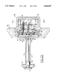
- FIG. 1 is a partial side elevation of an endoscopic insertion tube with portions broken away to better illustrate the steering section thereof;
- FIG. 2 is a top view showing the control wheels that are mounted upon the control handle of the insertion tube;
- FIG. 3 is an end view of the distal tip of the insertion tube taken along lines 3--3 in FIG. 1;
- FIG. 4 is an enlarged sectional view taken along lines 4--4 in FIG. 1;
- FIG. 5 is a further enlarged sectional view showing the up/down control wheel and a brake disc associated therewith in a control wheel engaging position;
- FIG. 6 is a sectional view taken along lines 6--6 in FIG. 5;
- FIG. 7 is a side elevation of a hub for mounting the up/down control wheel upon the control housing
- FIG. 8 is an end view of the hub shown in FIG. 7;
- FIG. 9 is a side view in section of the up/down brake disc
- FIG. 10 is a front view of the up/down brake disc
- FIGS. 11-13 are three views of the up/down brake actuator cover
- FIGS. 14 and 15 are two views of the up/down brake actuator arm hub
- FIGS. 16 and 17 are two views showing the up/down actuator arm
- FIGS. 18-20 are three views showing the up/down brake actuator arm assembly
- FIG. 21 is a sectional view similar to that of FIG. 5 showing the up/down brake disc in a disengaged position away from the adjacent up/down control wheel;
- FIG. 22 is a side elevation in section showing the left/right control wheel and an associated brake disc in engagement with the adjacent control wheel;
- FIG. 23 is a sectional view taken along lines 23--23 in FIG. 22;
- FIGS. 24 and 25 are two views of the left/right control wheel shaft
- FIGS. 26 and 27 are two views of the left/right brake disc.
- FIG. 28 is a sectional view similar to that of FIG. 22 showing the left/right brake disc in a disengaged position.
- FIG. 1 there is shown an insertion tube 10 of the type employed in a video endoscope.
- the distal end 11 of the insertion tube is equipped with viewing head 12 that contains a CCD solid state imager (not shown).
- the proximal end of the insertion tube contains a hand engageable control housing 13 that is shown in phantom outline in FIG. 1.
- Mounted inside the housing is a steering mechanism generally referenced 15.
- the steering mechanism includes a pair of rack and pinion units 17 and 18 that are attached to displacement cables for articulating the distal end of the insertion tube.
- the outer rack and pinion unit 17 is connected to a first left/right control wheel 20 by means of a hollow inner shaft 21.
- the racks 22 and 23 of the unit 17 are attached to displacement cables 24 so that rotation of the control wheel 20 in directions B and D (FIG. 2) will cause the distal end of the insertion tube to be bent in a horizontal plane either to the right or the left of the axial centerline of the insertion tube.
- the inner rack and pinion unit 18 is connected to a second up-down control wheel 26 via a second hollow shaft 27 that is housed inside a cylindrical support member 28 which forms part of the housing frame 19.
- the support member passes outwardly through the side wall 29 of the control housing and the opening closed by seal 30 and by the housing attachment ring 31.
- Racks 32 and 33 of the inner rack and pinion unit 18 are connected to displacement cables 34 whereby rotation of the second larger diameter wheel 26 in the A or C (FIG. 2) direction produces an up or down bending movement of the distal end of the insertion tube in a vertical plane.
- the distal end of the insertion tube can be directed in an infinite number of positions.
- the viewing head 12 is mounted at the distal tip of the insertion tube and contains an optical window 35 through which the CCD imager can view a target within the range of the viewing optics.
- Light is directed onto the target area by means of a pair of fiber bundles 36 and 37 situated on either side of the viewing window.
- a biopsy channel 38 also opens to the target region through the front face of the distal tip and permits instruments to be inserted therethrough to carry out various well-known procedures.
- the front face at the distal tip of the insertion tube can be pointed accurately at a target located in a remote and generally inaccessible region or the tube can be guided through tortuous passages.
- the left/right control wheel 20 is placed on the outside of the up/down control wheel 26.
- the wheels each have a different size diameter and the geometry of the wheels is also different.
- the outer wheel is smaller in diameter and contains four radially disposed spokes while the inner wheel has a larger diameter and contains five equally spaced spokes extending radially from the hub of the wheel.
- a person using the endoscope can rapidly identify each wheel by touch, thus allowing the user to continually view the target region on the video screen (not shown) to which the CCD imager is electrically connected.
- the sub assembly includes the previously noted left/right control wheel 20 which is secured to the hollow shaft 21 for rotation therewith.
- a pinion 41 is mounted on the inboard end of the shaft and mates with the rack 22 and 23 of the outer rack and pinion unit 17 (FIG. 4).
- a stationary support shaft 43 is contained within the hollow shaft 21 and is secured to the housing frame 19 by means of an end bracket 44.
- the shaft 21 is rotatably mounted upon the support shaft by means of bearings 45 and 46 whereupon the left/right control shaft can be freely rotated by turning the control in either direction B or D as seen in FIG. 2.
- control wheel In assembly, the control wheel is mounted on a square section 47 at the end of the hollow shaft 21 and is tightened against a shoulder 48 formed on the shaft. The wheel is held tightly against the shoulder by means of a jam nut 49 that is threaded onto the shaft behind the wheel and tightened against the end face of the wheel hub 50. Set screws 51--51 are threaded through the jam nut and are tightened down against the hub to further secure the wheel to the shaft.
- the right end of the support shaft 43 is equipped with a threaded shank 52 upon which an actuator knob 53 is mounted. Turning the actuator knob upon the shank causes the knob to move axially toward or away from the inner end face of the left/right control wheel hub 50.
- a floating brake disc 55 (FIGS. 26 and 27) having a square shaped centrally located hole 57 is mounted on a square section 56 of the support shaft 43 (FIGS. 24 and 25) so that the brake disc can move axially between the actuator knob and the hub of the left/right control wheel.
- the threaded shank of the support shaft is provided with a multiple thread whereby turning of the actuator knob will produce rapid axial movement of the knob toward or away from the control wheel 20.
- a pair of wave washer springs are mounted on either side of the brake disc 55.
- the spring rate of wave washer 59 is greater than that of wave washer 60, the reason for which will be explained in greater detail below.
- each of these wave washers can consist of several stacked individual wave washers.
- a ratchet mechanism is made up of detent pins 62 (preferably three) and a series of circumferentially spaced depressions 63--63 formed in the face of the brake face that is adjacent to the control wheel.
- the detent pins are staked into the hub of the control wheel and each has a rounded tip that is receivable into the circumferentially spaced depressions formed in the brake disc. Turning the actuating knob in one direction will cause the wave washer springs to be compressed and will force the brake disc into engaging contact with the detent pins, thus placing a biasing force upon the ratchet mechanism. This in turn places a braking torque upon the control wheel and a braking force on the associated displacement cable.
- the torque needed to do this depends on the net axial engagement force of the two springs, the geometry of the detent pin tips and the receiving depressions, the radial location of the depressions, and to a much lesser extent, upon the friction coefficient of the sliding surfaces of the ratchet mechanism.
- the braking torque achieved can be varied by changing the axial travel of the actuating knob and/or by changing the relative stiffness of the springs.
- the stop mechanism includes an axially disposed stud 64 which is threaded into one of a series of threaded holes 58--58 formed in the brake disc (FIG. 26).
- the stud is arranged to pass upwardly through an arcuate shaped slotted hole 65 formed in the hub of the actuator knob.
- a cylindrical sleeve 66 surrounds the stud 64 (FIG. 28).
- the slotted hole subtends an arc of about 180° thus permitting the knob to be advanced or retracted freely along the threaded shank of the support shaft about one-half a turn.
- a spring 69 is mounted in the hub of the actuator knob and is contoured to hold the stud in the extreme brake disc engaging and disengaging positions against the end walls of the slotted hole. The spring is attached to the actuator knob by screw 68.
- the actuator knob When the stud is bottomed against one end wall of the slotted hole, the actuator knob is retracted to the position shown in FIG. 28 and the compressive force on spring 59 is relieved. The softer spring 60 will now take over and push the brake disc away from the control wheel hub, thus disengaging the ratchet mechanism. This allows the control wheel to turn freely and smoothly during the steering operation. Turning the actuator knob in the opposite direction will bring the stud against the other end wall of the slotted hole, thus compressing the spring 59 and producing an engagement of the ratchet as explained above. At this time, the spring 59 acting through the ratchet mechanism will place a braking force against the left/right control wheel thus holding the distal tip of the insertion tube at a desired position in the horizontal plane.
- the control wheel can be incremented in either direction between the depressions in the brake disc by applying sufficient torque to the wheel to overcome the spring holding force.
- FIGS. 5-21 there is shown the sub assembly of the up/down control system which is generally referenced 70 (FIG. 21).
- the up/down control system operates in much the same manner as the left/right control system to apply a braking torque to the steering mechanism and thus hold the distal end of the insertion tube in a desired position in a vertical plane.
- the up/down control wheel 26 is secured for rotation to a square section 25 at the end of the hollow shaft 27 that surrounds the previously noted left/right control shaft 21.
- a pinion 72 is mounted on the inner end of the shaft and, as explained above, is arranged to engage a pair of racks for moving the up/down displacement cable 34 (FIG. 4) contained within the insertion tube.
- the control wheel is mounted on the outer end of the shaft and is tightened against a raised shoulder 71 from on the shaft.
- a jam nut 73 is threaded onto the shaft behind the hub of the control wheel to lock the hub against the shoulder.
- Set screws 74--74 are used to hold the jam nut securely against the control wheel in assembly.
- Three detent pins 76 are staked into the hub 69 of the control wheel and extend inwardly from the hub toward the up/down brake disc 77.
- a series of circumferentially spaced depressions 78--78 are formed in the front face of the brake disc for receiving the contoured tips of the detent pins 76.
- a cylindrical support member 28 surrounds the up/down control shaft.
- the support member is equipped with a radially expanded mounting flange 80 that is secured to the inside wall of the control housing by the housing attachment ring 31.
- the main body section of the support cylinder passes out of the housing through an opening in the housing side wall.
- the up/down brake disc 77 is slidably mounted on a flat section 81 (FIG. 7) of the support cylinder so that it can move axially toward and away from the hub of the up/down control wheel 26.
- a pair of wave washer springs 82 and 83 are positioned on either side of the brake disc.
- Spring 82 has a lower spring rate than spring 83 and is positioned between one face of the brake disc and the hub 69 of the control wheel 26.
- the other (heavier) spring 83 is positioned between the disc and an actuator unit generally referenced 85 (FIG. 6).
- each of these wave washer springs can consist of several stacked individual wave washers.
- the actuator unit 85 includes a cylindrical hub 86 (FIG. 14) having internal threads that permit the hub to be screwed onto the threaded section 87 (FIG. 7) on the support member 28.
- a lever arm 88 (FIG. 6) is secured to the front face 89 (FIG. 12) of a shroud 90 to clamp the hub therebetween.
- a yoke 91 which forms part of the shroud extends outwardly from the shroud. In assembly, the yoke overlies and partially encompasses the up/down brake disc.
- the brake disc 77 has a radially extended section 94 that contains a pair of slots 95 situated at each end of the radially extended section 94.
- the slots are adapted to receive therein tabs 96--96 that are carried on the circumferentially opposed ends of the shroud (FIG. 12).
- the deflection cable can be incremented in either direction by moving the pins between adjacent depressions.
- actuator knob 53 includes an outer cylindrical cap 100 that is press fitted upon an inner rotor 101 which is in turn threaded upon the outer end of support shaft 43.
- a series of spaced apart drain channels 103 are formed in the raised side wall of the rotor that allow any fluid trapped under the cap 100 to efficiently drain from beneath the knob thus rendering this region fluid free in the event the instrument is exposed to cleansing fluids or the like.
- the present control knob assembly because of its fluid insensitive brake system, is able to utilize a very simple sealing arrangement to prevent cleansing fluids and the like from entering the control housing 13 of the instrument when compared to other endoscopic braking systems.
- the sealing arrangement includes an O-ring seal 30 that acts between the support member 28 and the inner wall of the control housing.
- a series of two further O-rings 110 and 111 are mounted along the two pinion shafts 21 and 27 and finally an end O-ring seal 112 is mounted between the support shaft and inner shaft 21. Seals 110-112 prevent fluids from entering the control housing from between the shafts.
- the inner shaft O-ring 111 may transmit torque between the pinion shafts 21 and 27. As a result, rotation of one shaft may tend to cause the other shaft to rotate also. This can be avoided by eliminating O-ring 111 and, instead, placing an O-ring 114 between the inboard end of shaft 27 and the housing frame 19 and another O-ring 116 between the inboard end of shaft 21 and the housing frame 19.
- the apparatus of the present invention provides a braking system for the endoscope that is insensitive to fluids, such as cleaning fluids or the like, to which this type of instrument is exposed. It should be further noted, because of the arrangement of the present control and braking system, it can be securely mounted upon the control housing of the insertion tube of an endoscope employing a minimum number of seals. The overall construction of the control and braking system is thus greatly simplified without sacrificing reliability or efficiency of operation.
Abstract
Description
Claims (25)
Priority Applications (2)
| Application Number | Priority Date | Filing Date | Title |
|---|---|---|---|
| US08/200,383 US5464007A (en) | 1994-02-23 | 1994-02-23 | Fluid insensitive braking for an endoscope |
| US08/388,280 US5575755A (en) | 1994-02-23 | 1995-02-13 | Fluid insensitive braking for an endoscope |
Applications Claiming Priority (1)
| Application Number | Priority Date | Filing Date | Title |
|---|---|---|---|
| US08/200,383 US5464007A (en) | 1994-02-23 | 1994-02-23 | Fluid insensitive braking for an endoscope |
Related Child Applications (1)
| Application Number | Title | Priority Date | Filing Date |
|---|---|---|---|
| US08/388,280 Continuation-In-Part US5575755A (en) | 1994-02-23 | 1995-02-13 | Fluid insensitive braking for an endoscope |
Publications (1)
| Publication Number | Publication Date |
|---|---|
| US5464007A true US5464007A (en) | 1995-11-07 |
Family
ID=22741486
Family Applications (1)
| Application Number | Title | Priority Date | Filing Date |
|---|---|---|---|
| US08/200,383 Expired - Fee Related US5464007A (en) | 1994-02-23 | 1994-02-23 | Fluid insensitive braking for an endoscope |
Country Status (1)
| Country | Link |
|---|---|
| US (1) | US5464007A (en) |
Cited By (68)
| Publication number | Priority date | Publication date | Assignee | Title |
|---|---|---|---|---|
| US5575755A (en) * | 1994-02-23 | 1996-11-19 | Welch Allyn, Inc. | Fluid insensitive braking for an endoscope |
| US5888192A (en) * | 1996-12-06 | 1999-03-30 | Richard Wolf Gmbh | Control device for endocscopes |
| US6811532B2 (en) * | 2000-10-02 | 2004-11-02 | Olympus Corporation | Endoscope |
| US6837849B2 (en) * | 2000-10-02 | 2005-01-04 | Olympus Corporation | Endoscope |
| US6899673B2 (en) * | 2000-10-02 | 2005-05-31 | Olympus Corporation | Endoscope |
| US20060167343A1 (en) * | 2002-10-11 | 2006-07-27 | Michael Peszynski | Control mechanism for an endoscope |
| US20090240106A1 (en) * | 2008-03-05 | 2009-09-24 | Board Of Regents, The University Of Texas System | Endoscope With a Stimulating Electrode For Peripheral Nerve Blocks Under Direct Vision |
| US7846107B2 (en) | 2005-05-13 | 2010-12-07 | Boston Scientific Scimed, Inc. | Endoscopic apparatus with integrated multiple biopsy device |
| US20100324363A1 (en) * | 2008-03-05 | 2010-12-23 | Board Of Regents, The University Of Texas System | Disposable sheath designs for the stimulating endoscope and needle endoscopes having distal electrodes for nerve block under direct vision and methods for making and using same |
| US7955255B2 (en) | 2006-04-20 | 2011-06-07 | Boston Scientific Scimed, Inc. | Imaging assembly with transparent distal cap |
| US7967759B2 (en) | 2006-01-19 | 2011-06-28 | Boston Scientific Scimed, Inc. | Endoscopic system with integrated patient respiratory status indicator |
| US8052597B2 (en) | 2005-08-30 | 2011-11-08 | Boston Scientific Scimed, Inc. | Method for forming an endoscope articulation joint |
| US8083671B2 (en) | 2004-09-30 | 2011-12-27 | Boston Scientific Scimed, Inc. | Fluid delivery system for use with an endoscope |
| US8097003B2 (en) | 2005-05-13 | 2012-01-17 | Boston Scientific Scimed, Inc. | Endoscopic apparatus with integrated variceal ligation device |
| US8118732B2 (en) | 2003-04-01 | 2012-02-21 | Boston Scientific Scimed, Inc. | Force feedback control system for video endoscope |
| US8197400B2 (en) | 2004-09-30 | 2012-06-12 | Boston Scientific Scimed, Inc. | Selectively rotatable shaft coupler |
| US8199187B2 (en) | 2004-09-30 | 2012-06-12 | Boston Scientific Scimed, Inc. | Adapter for use with digital imaging medical device |
| US8202265B2 (en) | 2006-04-20 | 2012-06-19 | Boston Scientific Scimed, Inc. | Multiple lumen assembly for use in endoscopes or other medical devices |
| US8353860B2 (en) | 2004-09-30 | 2013-01-15 | Boston Scientific Scimed, Inc. | Device for obstruction removal with specific tip structure |
| US8357148B2 (en) | 2004-09-30 | 2013-01-22 | Boston Scientific Scimed, Inc. | Multi-functional endoscopic system for use in electrosurgical applications |
| US8425408B2 (en) | 2003-04-01 | 2013-04-23 | Boston Scientific Scimed, Inc. | Articulation joint for video endoscope |
| US20130102846A1 (en) * | 2011-10-21 | 2013-04-25 | Viking Systems, Inc. | Steerable electronic stereoscopic endoscope |
| US8435172B2 (en) | 2004-09-30 | 2013-05-07 | Boston Scientific Scimed, Inc. | Automated control of irrigation and aspiration in a single-use endoscope |
| US8475366B2 (en) | 2003-04-01 | 2013-07-02 | Boston Scientific Scimed, Inc. | Articulation joint for a medical device |
| US8535219B2 (en) | 2003-04-01 | 2013-09-17 | Boston Scientific Scimed, Inc. | Fluid manifold for endoscope system |
| US8622894B2 (en) | 2003-04-01 | 2014-01-07 | Boston Scientific Scimed, Inc. | Articulation joint |
| US8888684B2 (en) | 2006-03-27 | 2014-11-18 | Boston Scientific Scimed, Inc. | Medical devices with local drug delivery capabilities |
| WO2014186519A3 (en) * | 2013-05-17 | 2015-01-08 | Endochoice, Inc. | Endoscope control unit with braking system |
| US9474440B2 (en) | 2009-06-18 | 2016-10-25 | Endochoice, Inc. | Endoscope tip position visual indicator and heat management system |
| US9667935B2 (en) | 2013-05-07 | 2017-05-30 | Endochoice, Inc. | White balance enclosure for use with a multi-viewing elements endoscope |
| US9706908B2 (en) | 2010-10-28 | 2017-07-18 | Endochoice, Inc. | Image capture and video processing systems and methods for multiple viewing element endoscopes |
| US9943218B2 (en) | 2013-10-01 | 2018-04-17 | Endochoice, Inc. | Endoscope having a supply cable attached thereto |
| US9949623B2 (en) | 2013-05-17 | 2018-04-24 | Endochoice, Inc. | Endoscope control unit with braking system |
| US9968242B2 (en) | 2013-12-18 | 2018-05-15 | Endochoice, Inc. | Suction control unit for an endoscope having two working channels |
| US10064541B2 (en) | 2013-08-12 | 2018-09-04 | Endochoice, Inc. | Endoscope connector cover detection and warning system |
| US10078207B2 (en) | 2015-03-18 | 2018-09-18 | Endochoice, Inc. | Systems and methods for image magnification using relative movement between an image sensor and a lens assembly |
| US10105039B2 (en) | 2013-06-28 | 2018-10-23 | Endochoice, Inc. | Multi-jet distributor for an endoscope |
| US10123684B2 (en) | 2014-12-18 | 2018-11-13 | Endochoice, Inc. | System and method for processing video images generated by a multiple viewing elements endoscope |
| US10130246B2 (en) | 2009-06-18 | 2018-11-20 | Endochoice, Inc. | Systems and methods for regulating temperature and illumination intensity at the distal tip of an endoscope |
| CN109008902A (en) * | 2018-08-03 | 2018-12-18 | 苏州中科先进技术研究院有限公司 | A kind of endoscopic procedure portion and endoscope |
| CN109008904A (en) * | 2018-08-03 | 2018-12-18 | 苏州中科先进技术研究院有限公司 | A kind of endoscopic procedure portion and endoscope |
| CN109008901A (en) * | 2018-08-03 | 2018-12-18 | 苏州中科先进技术研究院有限公司 | A kind of medical endoscope bidirectional ratchet operating device |
| CN109008905A (en) * | 2018-08-03 | 2018-12-18 | 苏州中科先进技术研究院有限公司 | A kind of endoscopic procedure portion and endoscope |
| CN109008903A (en) * | 2018-08-03 | 2018-12-18 | 苏州中科先进技术研究院有限公司 | A kind of endoscopic procedure portion and endoscope |
| CN109077696A (en) * | 2018-08-03 | 2018-12-25 | 苏州中科先进技术研究院有限公司 | A kind of endoscope and its endoscope snake bone regulating device |
| CN109157180A (en) * | 2018-08-03 | 2019-01-08 | 苏州中科先进技术研究院有限公司 | A kind of medical endoscope ratchet operation device |
| CN109171603A (en) * | 2018-08-03 | 2019-01-11 | 苏州中科先进技术研究院有限公司 | A kind of endoscope turns to speed operating mechanism and driving method |
| CN109222855A (en) * | 2018-08-03 | 2019-01-18 | 苏州中科先进技术研究院有限公司 | A kind of medical endoscope bidirectional ratchet operating device |
| US10258222B2 (en) | 2014-07-21 | 2019-04-16 | Endochoice, Inc. | Multi-focal, multi-camera endoscope systems |
| US10271713B2 (en) | 2015-01-05 | 2019-04-30 | Endochoice, Inc. | Tubed manifold of a multiple viewing elements endoscope |
| US10292570B2 (en) | 2016-03-14 | 2019-05-21 | Endochoice, Inc. | System and method for guiding and tracking a region of interest using an endoscope |
| US10376181B2 (en) | 2015-02-17 | 2019-08-13 | Endochoice, Inc. | System for detecting the location of an endoscopic device during a medical procedure |
| US10401611B2 (en) | 2015-04-27 | 2019-09-03 | Endochoice, Inc. | Endoscope with integrated measurement of distance to objects of interest |
| US10488648B2 (en) | 2016-02-24 | 2019-11-26 | Endochoice, Inc. | Circuit board assembly for a multiple viewing element endoscope using CMOS sensors |
| US10516865B2 (en) | 2015-05-17 | 2019-12-24 | Endochoice, Inc. | Endoscopic image enhancement using contrast limited adaptive histogram equalization (CLAHE) implemented in a processor |
| US10517464B2 (en) | 2011-02-07 | 2019-12-31 | Endochoice, Inc. | Multi-element cover for a multi-camera endoscope |
| US10524645B2 (en) | 2009-06-18 | 2020-01-07 | Endochoice, Inc. | Method and system for eliminating image motion blur in a multiple viewing elements endoscope |
| US10542877B2 (en) | 2014-08-29 | 2020-01-28 | Endochoice, Inc. | Systems and methods for varying stiffness of an endoscopic insertion tube |
| US10595714B2 (en) | 2013-03-28 | 2020-03-24 | Endochoice, Inc. | Multi-jet controller for an endoscope |
| US10663714B2 (en) | 2010-10-28 | 2020-05-26 | Endochoice, Inc. | Optical system for an endoscope |
| US10898062B2 (en) | 2015-11-24 | 2021-01-26 | Endochoice, Inc. | Disposable air/water and suction valves for an endoscope |
| US10993605B2 (en) | 2016-06-21 | 2021-05-04 | Endochoice, Inc. | Endoscope system with multiple connection interfaces to interface with different video data signal sources |
| US11082598B2 (en) | 2014-01-22 | 2021-08-03 | Endochoice, Inc. | Image capture and video processing systems and methods for multiple viewing element endoscopes |
| US11234581B2 (en) | 2014-05-02 | 2022-02-01 | Endochoice, Inc. | Elevator for directing medical tool |
| US11529197B2 (en) | 2015-10-28 | 2022-12-20 | Endochoice, Inc. | Device and method for tracking the position of an endoscope within a patient's body |
| US20230145569A1 (en) * | 2004-03-23 | 2023-05-11 | Boston Scientific Scimed, Inc. | In-vivo visualization system |
| US11786112B2 (en) | 2020-04-30 | 2023-10-17 | Ambu A/S | Endoscope control system |
| US11957312B2 (en) | 2021-11-04 | 2024-04-16 | Boston Scientific Scimed, Inc. | Method for forming an endoscope articulation joint |
Citations (9)
| Publication number | Priority date | Publication date | Assignee | Title |
|---|---|---|---|---|
| US4207873A (en) * | 1977-05-16 | 1980-06-17 | American Cystoscope Makers, Inc. | Endoscope deflection control |
| US4461282A (en) * | 1978-05-02 | 1984-07-24 | Kabushiki Kaisha Medos Kenkyusho | Mechanism for direction changing of endoscope top end |
| US4539586A (en) * | 1983-10-07 | 1985-09-03 | Welch Allyn Inc. | Connector module for video endoscopic system |
| US4617914A (en) * | 1984-05-04 | 1986-10-21 | Asahi Kogaku Kogyo Kabushiki Kaisha | End curving device for endoscope |
| US4742816A (en) * | 1986-05-02 | 1988-05-10 | Olympus Optical Co., Ltd. | Operation device for endoscopes |
| US4825850A (en) * | 1988-05-13 | 1989-05-02 | Opielab, Inc. | Contamination protection system for endoscope control handles |
| US5007406A (en) * | 1988-11-04 | 1991-04-16 | Asahi Kogaku Kogyo Kabushiki Kaisha | Bending control device of endoscope |
| US5014685A (en) * | 1988-07-13 | 1991-05-14 | Asahi Kogaku Kogyo Kabushiki Kaisha | Brake for bending control device of endoscope |
| US5329887A (en) * | 1992-04-03 | 1994-07-19 | Vision Sciences, Incorporated | Endoscope control assembly with removable control knob/brake assembly |
-
1994
- 1994-02-23 US US08/200,383 patent/US5464007A/en not_active Expired - Fee Related
Patent Citations (10)
| Publication number | Priority date | Publication date | Assignee | Title |
|---|---|---|---|---|
| US4207873A (en) * | 1977-05-16 | 1980-06-17 | American Cystoscope Makers, Inc. | Endoscope deflection control |
| US4461282A (en) * | 1978-05-02 | 1984-07-24 | Kabushiki Kaisha Medos Kenkyusho | Mechanism for direction changing of endoscope top end |
| US4539586A (en) * | 1983-10-07 | 1985-09-03 | Welch Allyn Inc. | Connector module for video endoscopic system |
| US4539586B1 (en) * | 1983-10-07 | 1991-12-17 | Welch Allyn Inc | |
| US4617914A (en) * | 1984-05-04 | 1986-10-21 | Asahi Kogaku Kogyo Kabushiki Kaisha | End curving device for endoscope |
| US4742816A (en) * | 1986-05-02 | 1988-05-10 | Olympus Optical Co., Ltd. | Operation device for endoscopes |
| US4825850A (en) * | 1988-05-13 | 1989-05-02 | Opielab, Inc. | Contamination protection system for endoscope control handles |
| US5014685A (en) * | 1988-07-13 | 1991-05-14 | Asahi Kogaku Kogyo Kabushiki Kaisha | Brake for bending control device of endoscope |
| US5007406A (en) * | 1988-11-04 | 1991-04-16 | Asahi Kogaku Kogyo Kabushiki Kaisha | Bending control device of endoscope |
| US5329887A (en) * | 1992-04-03 | 1994-07-19 | Vision Sciences, Incorporated | Endoscope control assembly with removable control knob/brake assembly |
Cited By (115)
| Publication number | Priority date | Publication date | Assignee | Title |
|---|---|---|---|---|
| US5575755A (en) * | 1994-02-23 | 1996-11-19 | Welch Allyn, Inc. | Fluid insensitive braking for an endoscope |
| US5888192A (en) * | 1996-12-06 | 1999-03-30 | Richard Wolf Gmbh | Control device for endocscopes |
| US6811532B2 (en) * | 2000-10-02 | 2004-11-02 | Olympus Corporation | Endoscope |
| US6837849B2 (en) * | 2000-10-02 | 2005-01-04 | Olympus Corporation | Endoscope |
| US6899673B2 (en) * | 2000-10-02 | 2005-05-31 | Olympus Corporation | Endoscope |
| US7588536B2 (en) | 2002-10-11 | 2009-09-15 | Koninklijke Philips Electronics N.V. | Control mechanism for an endoscope |
| US20060167343A1 (en) * | 2002-10-11 | 2006-07-27 | Michael Peszynski | Control mechanism for an endoscope |
| US9913573B2 (en) | 2003-04-01 | 2018-03-13 | Boston Scientific Scimed, Inc. | Endoscopic imaging system |
| US8622894B2 (en) | 2003-04-01 | 2014-01-07 | Boston Scientific Scimed, Inc. | Articulation joint |
| US8535219B2 (en) | 2003-04-01 | 2013-09-17 | Boston Scientific Scimed, Inc. | Fluid manifold for endoscope system |
| US11324395B2 (en) | 2003-04-01 | 2022-05-10 | Boston Scientific Scimed, Inc. | Endoscopic imaging system |
| US10765307B2 (en) | 2003-04-01 | 2020-09-08 | Boston Scientific Scimed, Inc. | Endoscopic imaging system |
| US8608648B2 (en) | 2003-04-01 | 2013-12-17 | Boston Scientific Scimed, Inc. | Articulation joint |
| US8475366B2 (en) | 2003-04-01 | 2013-07-02 | Boston Scientific Scimed, Inc. | Articulation joint for a medical device |
| US8425408B2 (en) | 2003-04-01 | 2013-04-23 | Boston Scientific Scimed, Inc. | Articulation joint for video endoscope |
| US8118732B2 (en) | 2003-04-01 | 2012-02-21 | Boston Scientific Scimed, Inc. | Force feedback control system for video endoscope |
| US20230148845A1 (en) * | 2004-03-23 | 2023-05-18 | Boston Scientific Scimed, Inc. | Vivo visualization system |
| US20230145569A1 (en) * | 2004-03-23 | 2023-05-11 | Boston Scientific Scimed, Inc. | In-vivo visualization system |
| US11832793B2 (en) * | 2004-03-23 | 2023-12-05 | Boston Scientific Scimed, Inc. | Vivo visualization system |
| US11819192B2 (en) * | 2004-03-23 | 2023-11-21 | Boston Scientific Scimed, Inc. | In-vivo visualization system |
| US8199187B2 (en) | 2004-09-30 | 2012-06-12 | Boston Scientific Scimed, Inc. | Adapter for use with digital imaging medical device |
| US8197400B2 (en) | 2004-09-30 | 2012-06-12 | Boston Scientific Scimed, Inc. | Selectively rotatable shaft coupler |
| US8353860B2 (en) | 2004-09-30 | 2013-01-15 | Boston Scientific Scimed, Inc. | Device for obstruction removal with specific tip structure |
| US8357148B2 (en) | 2004-09-30 | 2013-01-22 | Boston Scientific Scimed, Inc. | Multi-functional endoscopic system for use in electrosurgical applications |
| USRE46007E1 (en) | 2004-09-30 | 2016-05-24 | Boston Scientific Scimed, Inc. | Automated control of irrigation and aspiration in a single-use endoscope |
| US8435172B2 (en) | 2004-09-30 | 2013-05-07 | Boston Scientific Scimed, Inc. | Automated control of irrigation and aspiration in a single-use endoscope |
| US8083671B2 (en) | 2004-09-30 | 2011-12-27 | Boston Scientific Scimed, Inc. | Fluid delivery system for use with an endoscope |
| US8097003B2 (en) | 2005-05-13 | 2012-01-17 | Boston Scientific Scimed, Inc. | Endoscopic apparatus with integrated variceal ligation device |
| US7846107B2 (en) | 2005-05-13 | 2010-12-07 | Boston Scientific Scimed, Inc. | Endoscopic apparatus with integrated multiple biopsy device |
| US8585715B2 (en) | 2005-05-13 | 2013-11-19 | Boston Scientific Scimed, Inc. | Endoscopic apparatus with integrated variceal ligation device |
| US10052013B2 (en) | 2005-08-30 | 2018-08-21 | Boston Scientific Scimed, Inc. | Medical device comprising segments |
| US8052597B2 (en) | 2005-08-30 | 2011-11-08 | Boston Scientific Scimed, Inc. | Method for forming an endoscope articulation joint |
| US11191424B2 (en) | 2005-08-30 | 2021-12-07 | Boston Scientific Scimed, Inc. | Method for forming an endoscope articulation joint |
| US9439557B2 (en) | 2005-08-30 | 2016-09-13 | Boston Scientific Scimed, Inc. | Articulation joint |
| US7967759B2 (en) | 2006-01-19 | 2011-06-28 | Boston Scientific Scimed, Inc. | Endoscopic system with integrated patient respiratory status indicator |
| US8888684B2 (en) | 2006-03-27 | 2014-11-18 | Boston Scientific Scimed, Inc. | Medical devices with local drug delivery capabilities |
| US9358363B2 (en) | 2006-04-20 | 2016-06-07 | Boston Scientific Scimed, Inc. | Multiple lumen assembly for use in endoscopes or other medical devices |
| US8870753B2 (en) | 2006-04-20 | 2014-10-28 | Boston Scientific Scimed, Inc. | Imaging assembly with transparent distal cap |
| US8202265B2 (en) | 2006-04-20 | 2012-06-19 | Boston Scientific Scimed, Inc. | Multiple lumen assembly for use in endoscopes or other medical devices |
| US7955255B2 (en) | 2006-04-20 | 2011-06-07 | Boston Scientific Scimed, Inc. | Imaging assembly with transparent distal cap |
| US9986896B2 (en) | 2008-03-05 | 2018-06-05 | The Board Of Regents Of The University Of Texas System | Disposable sheath designs for the stimulating endoscope and needle endoscopes having distal electrodes for nerve block under direct vision and methods for making and using same |
| US20090240106A1 (en) * | 2008-03-05 | 2009-09-24 | Board Of Regents, The University Of Texas System | Endoscope With a Stimulating Electrode For Peripheral Nerve Blocks Under Direct Vision |
| US20100324363A1 (en) * | 2008-03-05 | 2010-12-23 | Board Of Regents, The University Of Texas System | Disposable sheath designs for the stimulating endoscope and needle endoscopes having distal electrodes for nerve block under direct vision and methods for making and using same |
| US9474440B2 (en) | 2009-06-18 | 2016-10-25 | Endochoice, Inc. | Endoscope tip position visual indicator and heat management system |
| US10912454B2 (en) | 2009-06-18 | 2021-02-09 | Endochoice, Inc. | Systems and methods for regulating temperature and illumination intensity at the distal tip of an endoscope |
| US10561308B2 (en) | 2009-06-18 | 2020-02-18 | Endochoice, Inc. | Systems and methods for regulating temperature and illumination intensity at the distal tip of an endoscope |
| US10524645B2 (en) | 2009-06-18 | 2020-01-07 | Endochoice, Inc. | Method and system for eliminating image motion blur in a multiple viewing elements endoscope |
| US10130246B2 (en) | 2009-06-18 | 2018-11-20 | Endochoice, Inc. | Systems and methods for regulating temperature and illumination intensity at the distal tip of an endoscope |
| US9907462B2 (en) | 2009-06-18 | 2018-03-06 | Endochoice, Inc. | Endoscope tip position visual indicator and heat management system |
| US10412290B2 (en) | 2010-10-28 | 2019-09-10 | Endochoice, Inc. | Image capture and video processing systems and methods for multiple viewing element endoscopes |
| US10663714B2 (en) | 2010-10-28 | 2020-05-26 | Endochoice, Inc. | Optical system for an endoscope |
| US9706908B2 (en) | 2010-10-28 | 2017-07-18 | Endochoice, Inc. | Image capture and video processing systems and methods for multiple viewing element endoscopes |
| US10517464B2 (en) | 2011-02-07 | 2019-12-31 | Endochoice, Inc. | Multi-element cover for a multi-camera endoscope |
| US10779707B2 (en) | 2011-02-07 | 2020-09-22 | Endochoice, Inc. | Multi-element cover for a multi-camera endoscope |
| US9044138B2 (en) * | 2011-10-21 | 2015-06-02 | Viking Systems, Inc. | Steerable electronic stereoscopic endoscope |
| US20130102846A1 (en) * | 2011-10-21 | 2013-04-25 | Viking Systems, Inc. | Steerable electronic stereoscopic endoscope |
| US10595714B2 (en) | 2013-03-28 | 2020-03-24 | Endochoice, Inc. | Multi-jet controller for an endoscope |
| US11375885B2 (en) | 2013-03-28 | 2022-07-05 | Endochoice Inc. | Multi-jet controller for an endoscope |
| US10205925B2 (en) | 2013-05-07 | 2019-02-12 | Endochoice, Inc. | White balance enclosure for use with a multi-viewing elements endoscope |
| US9667935B2 (en) | 2013-05-07 | 2017-05-30 | Endochoice, Inc. | White balance enclosure for use with a multi-viewing elements endoscope |
| US20220104689A1 (en) * | 2013-05-17 | 2022-04-07 | Endochoice, Inc. | Endoscope control unit with braking system |
| US9949623B2 (en) | 2013-05-17 | 2018-04-24 | Endochoice, Inc. | Endoscope control unit with braking system |
| US11229351B2 (en) | 2013-05-17 | 2022-01-25 | Endochoice, Inc. | Endoscope control unit with braking system |
| WO2014186519A3 (en) * | 2013-05-17 | 2015-01-08 | Endochoice, Inc. | Endoscope control unit with braking system |
| US10433715B2 (en) | 2013-05-17 | 2019-10-08 | Endochoice, Inc. | Endoscope control unit with braking system |
| US10105039B2 (en) | 2013-06-28 | 2018-10-23 | Endochoice, Inc. | Multi-jet distributor for an endoscope |
| US10064541B2 (en) | 2013-08-12 | 2018-09-04 | Endochoice, Inc. | Endoscope connector cover detection and warning system |
| US9943218B2 (en) | 2013-10-01 | 2018-04-17 | Endochoice, Inc. | Endoscope having a supply cable attached thereto |
| US9968242B2 (en) | 2013-12-18 | 2018-05-15 | Endochoice, Inc. | Suction control unit for an endoscope having two working channels |
| US11082598B2 (en) | 2014-01-22 | 2021-08-03 | Endochoice, Inc. | Image capture and video processing systems and methods for multiple viewing element endoscopes |
| US11234581B2 (en) | 2014-05-02 | 2022-02-01 | Endochoice, Inc. | Elevator for directing medical tool |
| US10258222B2 (en) | 2014-07-21 | 2019-04-16 | Endochoice, Inc. | Multi-focal, multi-camera endoscope systems |
| US11883004B2 (en) | 2014-07-21 | 2024-01-30 | Endochoice, Inc. | Multi-focal, multi-camera endoscope systems |
| US11229348B2 (en) | 2014-07-21 | 2022-01-25 | Endochoice, Inc. | Multi-focal, multi-camera endoscope systems |
| US10542877B2 (en) | 2014-08-29 | 2020-01-28 | Endochoice, Inc. | Systems and methods for varying stiffness of an endoscopic insertion tube |
| US11771310B2 (en) | 2014-08-29 | 2023-10-03 | Endochoice, Inc. | Systems and methods for varying stiffness of an endoscopic insertion tube |
| US10123684B2 (en) | 2014-12-18 | 2018-11-13 | Endochoice, Inc. | System and method for processing video images generated by a multiple viewing elements endoscope |
| US10271713B2 (en) | 2015-01-05 | 2019-04-30 | Endochoice, Inc. | Tubed manifold of a multiple viewing elements endoscope |
| US10376181B2 (en) | 2015-02-17 | 2019-08-13 | Endochoice, Inc. | System for detecting the location of an endoscopic device during a medical procedure |
| US11147469B2 (en) | 2015-02-17 | 2021-10-19 | Endochoice, Inc. | System for detecting the location of an endoscopic device during a medical procedure |
| US10078207B2 (en) | 2015-03-18 | 2018-09-18 | Endochoice, Inc. | Systems and methods for image magnification using relative movement between an image sensor and a lens assembly |
| US10634900B2 (en) | 2015-03-18 | 2020-04-28 | Endochoice, Inc. | Systems and methods for image magnification using relative movement between an image sensor and a lens assembly |
| US11194151B2 (en) | 2015-03-18 | 2021-12-07 | Endochoice, Inc. | Systems and methods for image magnification using relative movement between an image sensor and a lens assembly |
| US10401611B2 (en) | 2015-04-27 | 2019-09-03 | Endochoice, Inc. | Endoscope with integrated measurement of distance to objects of interest |
| US11555997B2 (en) | 2015-04-27 | 2023-01-17 | Endochoice, Inc. | Endoscope with integrated measurement of distance to objects of interest |
| US10791308B2 (en) | 2015-05-17 | 2020-09-29 | Endochoice, Inc. | Endoscopic image enhancement using contrast limited adaptive histogram equalization (CLAHE) implemented in a processor |
| US11750782B2 (en) | 2015-05-17 | 2023-09-05 | Endochoice, Inc. | Endoscopic image enhancement using contrast limited adaptive histogram equalization (CLAHE) implemented in a processor |
| US10516865B2 (en) | 2015-05-17 | 2019-12-24 | Endochoice, Inc. | Endoscopic image enhancement using contrast limited adaptive histogram equalization (CLAHE) implemented in a processor |
| US11330238B2 (en) | 2015-05-17 | 2022-05-10 | Endochoice, Inc. | Endoscopic image enhancement using contrast limited adaptive histogram equalization (CLAHE) implemented in a processor |
| US11529197B2 (en) | 2015-10-28 | 2022-12-20 | Endochoice, Inc. | Device and method for tracking the position of an endoscope within a patient's body |
| US11311181B2 (en) | 2015-11-24 | 2022-04-26 | Endochoice, Inc. | Disposable air/water and suction valves for an endoscope |
| US10898062B2 (en) | 2015-11-24 | 2021-01-26 | Endochoice, Inc. | Disposable air/water and suction valves for an endoscope |
| US10908407B2 (en) | 2016-02-24 | 2021-02-02 | Endochoice, Inc. | Circuit board assembly for a multiple viewing elements endoscope using CMOS sensors |
| US10488648B2 (en) | 2016-02-24 | 2019-11-26 | Endochoice, Inc. | Circuit board assembly for a multiple viewing element endoscope using CMOS sensors |
| US11782259B2 (en) | 2016-02-24 | 2023-10-10 | Endochoice, Inc. | Circuit board assembly for a multiple viewing elements endoscope using CMOS sensors |
| US10292570B2 (en) | 2016-03-14 | 2019-05-21 | Endochoice, Inc. | System and method for guiding and tracking a region of interest using an endoscope |
| US10993605B2 (en) | 2016-06-21 | 2021-05-04 | Endochoice, Inc. | Endoscope system with multiple connection interfaces to interface with different video data signal sources |
| US11672407B2 (en) | 2016-06-21 | 2023-06-13 | Endochoice, Inc. | Endoscope system with multiple connection interfaces to interface with different video data signal sources |
| CN109008903B (en) * | 2018-08-03 | 2020-11-13 | 苏州中科先进技术研究院有限公司 | Endoscope operation part and endoscope |
| CN109008905A (en) * | 2018-08-03 | 2018-12-18 | 苏州中科先进技术研究院有限公司 | A kind of endoscopic procedure portion and endoscope |
| CN109008902B (en) * | 2018-08-03 | 2020-11-13 | 苏州中科先进技术研究院有限公司 | Endoscope operation part and endoscope |
| CN109222855A (en) * | 2018-08-03 | 2019-01-18 | 苏州中科先进技术研究院有限公司 | A kind of medical endoscope bidirectional ratchet operating device |
| CN109171603A (en) * | 2018-08-03 | 2019-01-11 | 苏州中科先进技术研究院有限公司 | A kind of endoscope turns to speed operating mechanism and driving method |
| CN109157180A (en) * | 2018-08-03 | 2019-01-08 | 苏州中科先进技术研究院有限公司 | A kind of medical endoscope ratchet operation device |
| CN109077696A (en) * | 2018-08-03 | 2018-12-25 | 苏州中科先进技术研究院有限公司 | A kind of endoscope and its endoscope snake bone regulating device |
| CN109008901B (en) * | 2018-08-03 | 2020-11-13 | 苏州中科先进技术研究院有限公司 | Bidirectional ratchet wheel operating device for medical endoscope |
| CN109008903A (en) * | 2018-08-03 | 2018-12-18 | 苏州中科先进技术研究院有限公司 | A kind of endoscopic procedure portion and endoscope |
| CN109008905B (en) * | 2018-08-03 | 2021-05-18 | 苏州中科先进技术研究院有限公司 | Endoscope operation part and endoscope |
| CN109008904B (en) * | 2018-08-03 | 2020-12-18 | 苏州中科先进技术研究院有限公司 | Endoscope operation part and endoscope |
| CN109008902A (en) * | 2018-08-03 | 2018-12-18 | 苏州中科先进技术研究院有限公司 | A kind of endoscopic procedure portion and endoscope |
| CN109008901A (en) * | 2018-08-03 | 2018-12-18 | 苏州中科先进技术研究院有限公司 | A kind of medical endoscope bidirectional ratchet operating device |
| CN109008904A (en) * | 2018-08-03 | 2018-12-18 | 苏州中科先进技术研究院有限公司 | A kind of endoscopic procedure portion and endoscope |
| US11786112B2 (en) | 2020-04-30 | 2023-10-17 | Ambu A/S | Endoscope control system |
| US11957312B2 (en) | 2021-11-04 | 2024-04-16 | Boston Scientific Scimed, Inc. | Method for forming an endoscope articulation joint |
| US11957311B2 (en) * | 2021-12-14 | 2024-04-16 | Endochoice, Inc. | Endoscope control unit with braking system |
Similar Documents
| Publication | Publication Date | Title |
|---|---|---|
| US5464007A (en) | Fluid insensitive braking for an endoscope | |
| US5575755A (en) | Fluid insensitive braking for an endoscope | |
| US4942866A (en) | Bending control apparatus for endoscope | |
| US8845521B2 (en) | Torque limiting mechanism of bendable portion control device for an endoscope | |
| US6210398B1 (en) | Manipulating part of endoscopic treatment tool | |
| US7828725B2 (en) | Bent state holding mechanism of an endoscope | |
| EP3025668B1 (en) | Tool holding articulated arm | |
| US5359994A (en) | Proximal steering cable adjustment | |
| JP3745757B2 (en) | Rotation limiter for catheter with flexible tip | |
| EP0677275B1 (en) | Surgical instrument | |
| US7846089B2 (en) | Bendable portion control mechanism of an endoscope | |
| US6569105B1 (en) | Rotatable and deflectable biopsy forceps | |
| CA1305900C (en) | Contamination protection system for endoscope control handles | |
| US20120277535A1 (en) | Bending operation device for endoscope and the endoscope | |
| US5391014A (en) | Universally rotatable nipple for a brake cable | |
| EP0486002A1 (en) | Quick release apparatus for a bicycle | |
| EP1555929B1 (en) | Control mechanism for an endoscope | |
| EP4090223A1 (en) | Endoscope control handle with a steering assembly | |
| US20230286179A1 (en) | Constraint mechanisms, systems, and methods | |
| GB2070715A (en) | Endoscope | |
| JP4323300B2 (en) | Endoscope | |
| JP2001112781A (en) | Dental or surgical angle piece | |
| EP4104747B1 (en) | Grasping mechanism for side-loading optical endoscopes and endoscope camera head with endoscope eyepiece grasping mechanism | |
| JPH0560734B2 (en) | ||
| CN111166275A (en) | Endoscope operating handle with four-direction bending angle and endoscope |
Legal Events
| Date | Code | Title | Description |
|---|---|---|---|
| AS | Assignment |
Owner name: WELCH ALLYN, INC., NEW YORK Free format text: ASSIGNMENT OF ASSIGNORS INTEREST;ASSIGNORS:KRAUTER, ALLAN I.;VIVENZIO, ROBERT L.;KEHOSKIE, MICHAEL P.;REEL/FRAME:006890/0996 Effective date: 19940222 |
|
| FEPP | Fee payment procedure |
Free format text: PAYOR NUMBER ASSIGNED (ORIGINAL EVENT CODE: ASPN); ENTITY STATUS OF PATENT OWNER: LARGE ENTITY |
|
| FPAY | Fee payment |
Year of fee payment: 4 |
|
| FPAY | Fee payment |
Year of fee payment: 8 |
|
| REMI | Maintenance fee reminder mailed | ||
| REMI | Maintenance fee reminder mailed | ||
| LAPS | Lapse for failure to pay maintenance fees | ||
| STCH | Information on status: patent discontinuation |
Free format text: PATENT EXPIRED DUE TO NONPAYMENT OF MAINTENANCE FEES UNDER 37 CFR 1.362 |
|
| FP | Lapsed due to failure to pay maintenance fee |
Effective date: 20071107 |