US5456533A - Static mixing element having deflectors and a mixing device - Google Patents
Static mixing element having deflectors and a mixing device Download PDFInfo
- Publication number
- US5456533A US5456533A US07/921,048 US92104892A US5456533A US 5456533 A US5456533 A US 5456533A US 92104892 A US92104892 A US 92104892A US 5456533 A US5456533 A US 5456533A
- Authority
- US
- United States
- Prior art keywords
- deflectors
- channel
- flow channel
- static mixing
- flow direction
- Prior art date
- Legal status (The legal status is an assumption and is not a legal conclusion. Google has not performed a legal analysis and makes no representation as to the accuracy of the status listed.)
- Expired - Lifetime
Links
- 238000002156 mixing Methods 0.000 title claims abstract description 57
- 230000003068 static effect Effects 0.000 title claims abstract description 15
- QGZKDVFQNNGYKY-UHFFFAOYSA-N Ammonia Chemical compound N QGZKDVFQNNGYKY-UHFFFAOYSA-N 0.000 claims description 14
- 238000002347 injection Methods 0.000 claims description 8
- 239000007924 injection Substances 0.000 claims description 8
- 229910021529 ammonia Inorganic materials 0.000 claims description 6
- UGFAIRIUMAVXCW-UHFFFAOYSA-N Carbon monoxide Chemical compound [O+]#[C-] UGFAIRIUMAVXCW-UHFFFAOYSA-N 0.000 claims description 5
- 239000003546 flue gas Substances 0.000 claims description 5
- 239000007788 liquid Substances 0.000 claims description 3
- 239000012530 fluid Substances 0.000 description 9
- 239000002184 metal Substances 0.000 description 4
- 239000007789 gas Substances 0.000 description 2
- 238000000265 homogenisation Methods 0.000 description 2
- 238000009434 installation Methods 0.000 description 2
- 238000004519 manufacturing process Methods 0.000 description 2
- 230000001154 acute effect Effects 0.000 description 1
- 238000005452 bending Methods 0.000 description 1
- 239000003054 catalyst Substances 0.000 description 1
- 238000010276 construction Methods 0.000 description 1
- 230000009977 dual effect Effects 0.000 description 1
- 238000011068 loading method Methods 0.000 description 1
- 229910000069 nitrogen hydride Inorganic materials 0.000 description 1
- 230000002787 reinforcement Effects 0.000 description 1
- 238000005728 strengthening Methods 0.000 description 1
- 238000009827 uniform distribution Methods 0.000 description 1
Images


Classifications
-
- B—PERFORMING OPERATIONS; TRANSPORTING
- B01—PHYSICAL OR CHEMICAL PROCESSES OR APPARATUS IN GENERAL
- B01F—MIXING, e.g. DISSOLVING, EMULSIFYING OR DISPERSING
- B01F25/00—Flow mixers; Mixers for falling materials, e.g. solid particles
- B01F25/40—Static mixers
- B01F25/42—Static mixers in which the mixing is affected by moving the components jointly in changing directions, e.g. in tubes provided with baffles or obstructions
- B01F25/43—Mixing tubes, e.g. wherein the material is moved in a radial or partly reversed direction
- B01F25/431—Straight mixing tubes with baffles or obstructions that do not cause substantial pressure drop; Baffles therefor
- B01F25/4316—Straight mixing tubes with baffles or obstructions that do not cause substantial pressure drop; Baffles therefor the baffles being flat pieces of material, e.g. intermeshing, fixed to the wall or fixed on a central rod
- B01F25/43161—Straight mixing tubes with baffles or obstructions that do not cause substantial pressure drop; Baffles therefor the baffles being flat pieces of material, e.g. intermeshing, fixed to the wall or fixed on a central rod composed of consecutive sections of flat pieces of material
-
- B—PERFORMING OPERATIONS; TRANSPORTING
- B01—PHYSICAL OR CHEMICAL PROCESSES OR APPARATUS IN GENERAL
- B01F—MIXING, e.g. DISSOLVING, EMULSIFYING OR DISPERSING
- B01F25/00—Flow mixers; Mixers for falling materials, e.g. solid particles
- B01F25/30—Injector mixers
- B01F25/31—Injector mixers in conduits or tubes through which the main component flows
- B01F25/313—Injector mixers in conduits or tubes through which the main component flows wherein additional components are introduced in the centre of the conduit
- B01F25/3131—Injector mixers in conduits or tubes through which the main component flows wherein additional components are introduced in the centre of the conduit with additional mixing means other than injector mixers, e.g. screens, baffles or rotating elements
-
- B—PERFORMING OPERATIONS; TRANSPORTING
- B01—PHYSICAL OR CHEMICAL PROCESSES OR APPARATUS IN GENERAL
- B01F—MIXING, e.g. DISSOLVING, EMULSIFYING OR DISPERSING
- B01F25/00—Flow mixers; Mixers for falling materials, e.g. solid particles
- B01F25/40—Static mixers
- B01F25/42—Static mixers in which the mixing is affected by moving the components jointly in changing directions, e.g. in tubes provided with baffles or obstructions
- B01F25/43—Mixing tubes, e.g. wherein the material is moved in a radial or partly reversed direction
- B01F25/431—Straight mixing tubes with baffles or obstructions that do not cause substantial pressure drop; Baffles therefor
- B01F25/4315—Straight mixing tubes with baffles or obstructions that do not cause substantial pressure drop; Baffles therefor the baffles being deformed flat pieces of material
-
- B—PERFORMING OPERATIONS; TRANSPORTING
- B01—PHYSICAL OR CHEMICAL PROCESSES OR APPARATUS IN GENERAL
- B01F—MIXING, e.g. DISSOLVING, EMULSIFYING OR DISPERSING
- B01F25/00—Flow mixers; Mixers for falling materials, e.g. solid particles
- B01F25/40—Static mixers
- B01F25/42—Static mixers in which the mixing is affected by moving the components jointly in changing directions, e.g. in tubes provided with baffles or obstructions
- B01F25/43—Mixing tubes, e.g. wherein the material is moved in a radial or partly reversed direction
- B01F25/431—Straight mixing tubes with baffles or obstructions that do not cause substantial pressure drop; Baffles therefor
- B01F25/4316—Straight mixing tubes with baffles or obstructions that do not cause substantial pressure drop; Baffles therefor the baffles being flat pieces of material, e.g. intermeshing, fixed to the wall or fixed on a central rod
- B01F25/43163—Straight mixing tubes with baffles or obstructions that do not cause substantial pressure drop; Baffles therefor the baffles being flat pieces of material, e.g. intermeshing, fixed to the wall or fixed on a central rod in the form of small flat plate-like elements
-
- B—PERFORMING OPERATIONS; TRANSPORTING
- B01—PHYSICAL OR CHEMICAL PROCESSES OR APPARATUS IN GENERAL
- B01F—MIXING, e.g. DISSOLVING, EMULSIFYING OR DISPERSING
- B01F25/00—Flow mixers; Mixers for falling materials, e.g. solid particles
- B01F25/40—Static mixers
- B01F25/42—Static mixers in which the mixing is affected by moving the components jointly in changing directions, e.g. in tubes provided with baffles or obstructions
- B01F25/43—Mixing tubes, e.g. wherein the material is moved in a radial or partly reversed direction
- B01F25/431—Straight mixing tubes with baffles or obstructions that do not cause substantial pressure drop; Baffles therefor
- B01F25/43197—Straight mixing tubes with baffles or obstructions that do not cause substantial pressure drop; Baffles therefor characterised by the mounting of the baffles or obstructions
- B01F25/431973—Mounted on a support member extending transversally through the mixing tube
-
- B—PERFORMING OPERATIONS; TRANSPORTING
- B01—PHYSICAL OR CHEMICAL PROCESSES OR APPARATUS IN GENERAL
- B01F—MIXING, e.g. DISSOLVING, EMULSIFYING OR DISPERSING
- B01F25/00—Flow mixers; Mixers for falling materials, e.g. solid particles
- B01F25/40—Static mixers
- B01F25/42—Static mixers in which the mixing is affected by moving the components jointly in changing directions, e.g. in tubes provided with baffles or obstructions
- B01F25/43—Mixing tubes, e.g. wherein the material is moved in a radial or partly reversed direction
- B01F25/431—Straight mixing tubes with baffles or obstructions that do not cause substantial pressure drop; Baffles therefor
- B01F25/4319—Tubular elements
Definitions
- the invention relates to a static mixing element in a flow channel, the element having at least two deflectors, and to a mixing device having such element.
- Simple static mixing elements having deflectors are known but their mixing and homogenising abilities are very limited and they always produce a relatively high pressure drop.
- More elaborate static mixers, for example, comprising crossing subchannels of slats (Sulzer-SMV-mixers) provide very good mixing but are relatively costly to produce. Good mixing is particularly necessary when a small quantity of a fluid is injected by means of an injection system into a main flow of another fluid in a flow channel.
- denitrogenation is performed by admixing gaseous ammonia into the flue gas flow in a very low proportion of from 1 : 1000 to 1 : 10 000; very thorough homogeneity is required, with a maximum deviation of less than 5% from the average value, to ensure that in the subsequent catalyst the reaction of NH3 with NOX proceeds very uniformly everywhere, in order to keep within low nox limits and also to ensure that no surplus ammonia breaks through.
- the stoichiometric mixing ratios must therefore be maintained uniformly and permanently over the whole channel cross-section. Also, this thorough mixing must be achieved over short paths and with a low pressure drop and known mixing devices cannot provide these two features.
- the invention solves these problems by means of a mixing element having deflectors attached to a mounting at a distance from the channel wall.
- the deflectors form an angle of between 10° and 45° relative to the main flow direction.
- a projection of the deflectors in the main flow direction amounts to between 5% and 50% of the channel cross-sectional area. Since deflectors are disposed by means of mountings at a distance from the channel wall, the deflectors are flowed around completely at the front and back with very reduced losses, with the result that efficient deflection and eddying are produced in the direction of the angle W.
- the provision of a few deflectors with different orientations is a very simple means of producing crossing radial subflows with a reduced pressure drop.
- the dispensing tube injects the fluid for mixing along its axis at the same piece into the deflected turbulence cone. Immediate intensive mixing of the two fluids is therefore produced and the local deflection in the directions W of the at least two oppositely orientated deflectors produces a cross-flow causing intensive mixing over the whole flow channel cross-section.
- the device according to the invention produces intensive mixing of the two fluids in the injection zone and good homogenization over the entire channel cross-section by simple means and with a reduced pressure drop.
- the projection FZ of the deflectors in the main flow direction can be as little as from 5% to 25% of the channel cross-section and therefore lead to optimal mixing with very reduced complexity and a very reduced pressure drop.
- the deflectors can be rectangular or triangular or trapezoidal or round or bent or curved or cylindrical and even perforate, they can be staggered relatively to one another and, in a substantially uniform distribution, can cover the complete channel cross-section.
- At least two consecutive mixing elements of this kind can form a mixer arrangement, the elements possibly having deflectors which are offset or turned relatively to one another.
- a mixing element can be followed by an aftermixing section or path which further enhances mixing.
- the deflectors can be at least ten times as large as the outlet cross-section of a dispensing tube and the angle WE with the tube axis can be between 0° and 15°.
- the devices according to the invention are particularly suitable for mixing ammonia into the flue gas flow of a denitrogenation installation.
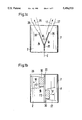
- FIGS. 1a and 1b are two views of a mixing element according to the invention which has two deflectors and is on a mounting;
- FIG. 2 shows an example having a number of deflectors which cover the channel cross-section F regularly
- FIGS. 3a to 3d show examples of deflector shapes
- FIGS. 4a and 4b show examples in which different deflectors are disposed in round flow channels
- FIG. 5 shows a mixer arrangement in which deflectors are disposed in two cross-sectional planes of the flow channel
- FIGS. 6a and 6b show examples of deflectors with mountings punched from sheet metal strip
- FIG. 7 shows a mixer arrangement comprising two mixing elements and an aftermixing path
- FIGS. 8a and 8b are two views showing a mixing device according to the invention having two dispensing tubes as mountings and two deflectors;
- FIGS. 9a and 9b show another example comprising a dispensing tube and two deflectors
- FIG. 10 shows an example having a number of dispensing tubes and deflectors
- FIGS. 11a, 11b, 11c and 11d show various examples of deflectors in dispensing tubes.
- FIG. 12 shows a mixing device having dispensing tubes and deflectors in two planes.
- FIG. 1 shows two views of a mixing element 4 according to the invention comprising two deflectors 30 which are secured by way of a mounting 20 in a flow channel 7.
- the rectangular deflectors 30 are staggered relatively to one another and are each inclined, in opposite orientations to one another, to the main flow direction 8 of the fluid 2 at an angle W of e.g. 30°.
- the deflectors 30 produce corresponding turbulent flow cones 26, 27 which are deflected in the directions 16, 17 and which cross one another in staggered relationship.
- the projection FZ of the two deflectors in the flow direction Z amounts to less than 50% of the flow channel cross-sectional area F (see FIG. 1b).
- a proportion FZ of as little as e.g. from 10% to 20% of F can according to the invention produce turbulent and intensively mixing cross-flows.
- FIG. 2 shows a similar example having a number of deflectors 30 on two mountings 20 to provide regular covering of a complete channel cross-section F with the production of (in FIG. 2) alternately upwardly and downwardly directed subflows 16, 17 of the cross-flows they produce.
- the deflectors 30 can have different shapes and can be, for example, trapezoidal, as 31, or round, as 32, or even perforate, as 24.
- the mounting is in this case embodied by tubes which have fairly high inherent rigidity.
- the mounting and deflector can be a unitary device and, for example, as shown in FIG.
- FIG. 3 take the form of a bent stamping 33 which is welded to the channel wall, the narrow prolongation 23 of the wide deflector element 30 serving as mounting.
- FIG. 3d shows a similar but curved version 34.
- FIG. 4a shows deflectors of different shapes, for example, in round flow channels, two relatively small deflectors 35 extending to the left and a single central deflector 36 of substantially twice the size extending to the right.
- FIG. 4b shows a version having two different deflectors 37, 38 in dual form.
- the mounting can have reinforcements and stiffenings more particularly for high flow speeds and heavy deflector loadings.
- the strengthenings and stiffenings can be embodied together with the deflectors as lattice-like or checker-like structures as shown, for example, with the bracings 22 of FIGS. 4b and 5.
- the mounting can take the form of ropes on which the deflectors are set like sails in the required optimal direction W.
- FIG. 5 shows a mixer arrangement having deflectors in two cross-sectional planes 41, 42.
- the deflectors of plane 42 are staggered relatively to the deflectors of the first plane 41. They can also be turned relatively to one another, for example, by 90°.
- the arrangement of the deflectors 30, 39 in a single plane corresponds to the illustration of FIG. 2 except that in FIG. 5 larger rectangular deflectors are used which have a total area FZ (one plane) projected in the Z direction, corresponding to something like 50% of the cross-sectional area F.
- FZ one plane
- the deflectors 30, 39 are bent alternately to opposite sides, the residual strip 21 serving as mounting 20.
- the deflector arrangement of FIG. 2 can be produced by trapezoidal toothed stampings from a metal strip to give two rows of deflectors 30, 31 with mountings 20 from a single metal strip.
- FIG. 7 shows a mixer arrangement having two mixing elements 3, 4, at least the first mixing element 3 being followed by an aftermixing path N facilitating enhanced cross-mixing by the turbulent crossing subflows produced in the mixing element.
- the elements 3, 4 are turned away from one another by 90°.
- the arrangement shown in FIGS. 8a and 8b comprises a mixing device having two dispensing tubes 21 on a main tube 20 as mountings, one deflector 30 each being disposed at the dispensing tube outlet orifices 28 at an acute angle W to the main flow direction Z.
- the length L of the dispensing tubes 21 is at least equal to their diameter D.
- the deflectors 30 include an angle W2 of from 0° to 45° with the tube axis and are oriented oppositely to one another relatively to Z.
- the deflectors 30 produce deflected turbulent cones 26, 27 of the main fluid 2, such cones crossing the injected cones 8 of the admixed fluid 1 and thus being subject to intensive mixing.
- the two deflectors 30 and the dispensing tubes E1 are orientated in opposite directions relatively to Z and are staggered relatively to one another along the main tube 20. Crossing subflows 16, 17 are therefore produced, leading to intensive mixing and homogenization of the two fluids 1, a over the main channel cross-section.
- FIGS. 9a and 9b show an example having only a single dispensing tube El which extends parallel to the main flow direction Z, two deflectors 30 being disposed at the dispensing tube outlet orifice 28.
- the deflectors are oriented in opposite directions to one another and are offset from one another in order to produce crossing subflows 16, 17.
- FIG. 10 shows another injection device having a number of dispensing tubes 21 and deflectors 30 on two main tubes 20 as mountings, the deflectors 30 being distributed uniformly over the whole channel cross-section F.
- the main flow is therefore broken up uniformly by the offset and oppositely directed deflectors into crossing subflows whose directions 16, 17 extend alternately upwardly and downwardly.
- the deflectors 30 can be relatively large, their total area FZ which is projected in the Z direction preferably being between 5% and 50% of the area F. Very good mixing with a very reduced pressure drop is often achieved with an area ratio of from 10% to 15%.
- FIGS. 11a to 11d show various examples of appropriate forms of deflectors on the dispensing tubes --rectangular 43, triangular 44, round 45 or curved as a tubular element 46.
- FIG. 12 shows an arrangement having dispensing tubes 21 as mountings and deflectors 30 in two planes 41, 42, the dispensing tubes with deflectors of the second plane being staggered relatively to those of the first plane.
- the direction of the dispensing tubes having deflectors W in the second plane can be turned relatively to the direction in the first plane, preferably by 90°.
- the invention may also be used to admix ammonia from a source of ammonia 46 with a flue gas flow from a source of flue gas 47.
- mixing efficiency could be improved from 4% to just 2% concentration variation.
Abstract
The static mixing element in a flow channel (7) has at least two deflectors (30) disposed on mountings (20) at a distance from the channel wall. The deflectors form an angle W of from 10° to 45° to the main flow direction Z. They have different orientations and the projection FZ of the deflectors in the main flow direction amounts to from 5% to 50% of the channel cross-section F. Cross-flows providing very efficient transverse mixing are therefore produced in a simple manner. When dispensing tubes (20, 21) are used as mountings a very effective mixing device is provided.
Description
The invention relates to a static mixing element in a flow channel, the element having at least two deflectors, and to a mixing device having such element. Simple static mixing elements having deflectors are known but their mixing and homogenising abilities are very limited and they always produce a relatively high pressure drop. More elaborate static mixers, for example, comprising crossing subchannels of slats (Sulzer-SMV-mixers) provide very good mixing but are relatively costly to produce. Good mixing is particularly necessary when a small quantity of a fluid is injected by means of an injection system into a main flow of another fluid in a flow channel. When relatively small quantities, for example, of less than 10%, of a gas or a liquid are admixed into the flow of another gas or another liquid, very one mixing paths in the empty tube are necessary to ensure thorough homogeneous mixing. However, conventional mixing devices having complicated adjustable injection systems cannot provide thorough mixing over a wide range of loads and more particularly at very low volume flow relationships. For example, in denoxing installations denitrogenation is performed by admixing gaseous ammonia into the flue gas flow in a very low proportion of from 1 : 1000 to 1 : 10 000; very thorough homogeneity is required, with a maximum deviation of less than 5% from the average value, to ensure that in the subsequent catalyst the reaction of NH3 with NOX proceeds very uniformly everywhere, in order to keep within low nox limits and also to ensure that no surplus ammonia breaks through. The stoichiometric mixing ratios must therefore be maintained uniformly and permanently over the whole channel cross-section. Also, this thorough mixing must be achieved over short paths and with a low pressure drop and known mixing devices cannot provide these two features.
It is therefore the object of this invention, using very simple means, to provide very thorough mixing with a relatively low pressure drop and to provide overall advantages as compared with the known kinds of mixer, and it is another object of the invention to provide by means of the static mixing element a simple mixing device which ensures, with a reduced pressure drop and over short paths, high-quality mixing over the entire channel cross-section and over a wide range of load conditions.
The invention solves these problems by means of a mixing element having deflectors attached to a mounting at a distance from the channel wall. The deflectors form an angle of between 10° and 45° relative to the main flow direction. A projection of the deflectors in the main flow direction amounts to between 5% and 50% of the channel cross-sectional area. Since deflectors are disposed by means of mountings at a distance from the channel wall, the deflectors are flowed around completely at the front and back with very reduced losses, with the result that efficient deflection and eddying are produced in the direction of the angle W. The provision of a few deflectors with different orientations is a very simple means of producing crossing radial subflows with a reduced pressure drop. Because of the deflectors a relatively large turbulence cone is produced in the main flow and deflected in the direction W1. Simultaneously, the dispensing tube injects the fluid for mixing along its axis at the same piece into the deflected turbulence cone. Immediate intensive mixing of the two fluids is therefore produced and the local deflection in the directions W of the at least two oppositely orientated deflectors produces a cross-flow causing intensive mixing over the whole flow channel cross-section. In all, therefore, the device according to the invention produces intensive mixing of the two fluids in the injection zone and good homogenization over the entire channel cross-section by simple means and with a reduced pressure drop. The projection FZ of the deflectors in the main flow direction can be as little as from 5% to 25% of the channel cross-section and therefore lead to optimal mixing with very reduced complexity and a very reduced pressure drop. The deflectors can be rectangular or triangular or trapezoidal or round or bent or curved or cylindrical and even perforate, they can be staggered relatively to one another and, in a substantially uniform distribution, can cover the complete channel cross-section. At least two consecutive mixing elements of this kind can form a mixer arrangement, the elements possibly having deflectors which are offset or turned relatively to one another. A mixing element can be followed by an aftermixing section or path which further enhances mixing.
In particularly effective constructions the deflectors can be at least ten times as large as the outlet cross-section of a dispensing tube and the angle WE with the tube axis can be between 0° and 15°. The devices according to the invention are particularly suitable for mixing ammonia into the flue gas flow of a denitrogenation installation.
The invention will be further described hereinafter with reference to drawings and embodiments.
FIGS. 1a and 1b are two views of a mixing element according to the invention which has two deflectors and is on a mounting;
FIG. 2 shows an example having a number of deflectors which cover the channel cross-section F regularly;
FIGS. 3a to 3d show examples of deflector shapes;
FIGS. 4a and 4b show examples in which different deflectors are disposed in round flow channels;
FIG. 5 shows a mixer arrangement in which deflectors are disposed in two cross-sectional planes of the flow channel;
FIGS. 6a and 6b show examples of deflectors with mountings punched from sheet metal strip;
FIG. 7 shows a mixer arrangement comprising two mixing elements and an aftermixing path;
FIGS. 8a and 8b are two views showing a mixing device according to the invention having two dispensing tubes as mountings and two deflectors;
FIGS. 9a and 9b show another example comprising a dispensing tube and two deflectors;
FIG. 10 shows an example having a number of dispensing tubes and deflectors;
FIGS. 11a, 11b, 11c and 11d show various examples of deflectors in dispensing tubes, and
FIG. 12 shows a mixing device having dispensing tubes and deflectors in two planes.
FIG. 1 shows two views of a mixing element 4 according to the invention comprising two deflectors 30 which are secured by way of a mounting 20 in a flow channel 7. The rectangular deflectors 30 are staggered relatively to one another and are each inclined, in opposite orientations to one another, to the main flow direction 8 of the fluid 2 at an angle W of e.g. 30°. The deflectors 30 produce corresponding turbulent flow cones 26, 27 which are deflected in the directions 16, 17 and which cross one another in staggered relationship. The projection FZ of the two deflectors in the flow direction Z amounts to less than 50% of the flow channel cross-sectional area F (see FIG. 1b). A proportion FZ of as little as e.g. from 10% to 20% of F can according to the invention produce turbulent and intensively mixing cross-flows.
FIG. 2 shows a similar example having a number of deflectors 30 on two mountings 20 to provide regular covering of a complete channel cross-section F with the production of (in FIG. 2) alternately upwardly and downwardly directed subflows 16, 17 of the cross-flows they produce. According to FIGS. 3a to 3d the deflectors 30 can have different shapes and can be, for example, trapezoidal, as 31, or round, as 32, or even perforate, as 24. The mounting is in this case embodied by tubes which have fairly high inherent rigidity. The mounting and deflector can be a unitary device and, for example, as shown in FIG. 3, take the form of a bent stamping 33 which is welded to the channel wall, the narrow prolongation 23 of the wide deflector element 30 serving as mounting. FIG. 3d shows a similar but curved version 34. FIG. 4a shows deflectors of different shapes, for example, in round flow channels, two relatively small deflectors 35 extending to the left and a single central deflector 36 of substantially twice the size extending to the right. FIG. 4b shows a version having two different deflectors 37, 38 in dual form.
The mounting can have reinforcements and stiffenings more particularly for high flow speeds and heavy deflector loadings. The strengthenings and stiffenings can be embodied together with the deflectors as lattice-like or checker-like structures as shown, for example, with the bracings 22 of FIGS. 4b and 5. The mounting can take the form of ropes on which the deflectors are set like sails in the required optimal direction W.
FIG. 5 shows a mixer arrangement having deflectors in two cross-sectional planes 41, 42. The deflectors of plane 42 are staggered relatively to the deflectors of the first plane 41. They can also be turned relatively to one another, for example, by 90°. The arrangement of the deflectors 30, 39 in a single plane corresponds to the illustration of FIG. 2 except that in FIG. 5 larger rectangular deflectors are used which have a total area FZ (one plane) projected in the Z direction, corresponding to something like 50% of the cross-sectional area F. As FIG. 6a shows, the deflectors of FIG. 5 can be produced very simply, cheaply and without scrap from metal strip by stamping and bending. The deflectors 30, 39 are bent alternately to opposite sides, the residual strip 21 serving as mounting 20. Similarly, the deflector arrangement of FIG. 2 can be produced by trapezoidal toothed stampings from a metal strip to give two rows of deflectors 30, 31 with mountings 20 from a single metal strip.
FIG. 7 shows a mixer arrangement having two mixing elements 3, 4, at least the first mixing element 3 being followed by an aftermixing path N facilitating enhanced cross-mixing by the turbulent crossing subflows produced in the mixing element. In this embodiment the elements 3, 4 are turned away from one another by 90°.
The arrangement shown in FIGS. 8a and 8b comprises a mixing device having two dispensing tubes 21 on a main tube 20 as mountings, one deflector 30 each being disposed at the dispensing tube outlet orifices 28 at an acute angle W to the main flow direction Z. The length L of the dispensing tubes 21 is at least equal to their diameter D. The deflectors 30 include an angle W2 of from 0° to 45° with the tube axis and are oriented oppositely to one another relatively to Z. The deflectors 30 produce deflected turbulent cones 26, 27 of the main fluid 2, such cones crossing the injected cones 8 of the admixed fluid 1 and thus being subject to intensive mixing. The two deflectors 30 and the dispensing tubes E1 are orientated in opposite directions relatively to Z and are staggered relatively to one another along the main tube 20. Crossing subflows 16, 17 are therefore produced, leading to intensive mixing and homogenization of the two fluids 1, a over the main channel cross-section.
FIGS. 9a and 9b show an example having only a single dispensing tube El which extends parallel to the main flow direction Z, two deflectors 30 being disposed at the dispensing tube outlet orifice 28. The deflectors are oriented in opposite directions to one another and are offset from one another in order to produce crossing subflows 16, 17.
FIG. 10 shows another injection device having a number of dispensing tubes 21 and deflectors 30 on two main tubes 20 as mountings, the deflectors 30 being distributed uniformly over the whole channel cross-section F. The main flow is therefore broken up uniformly by the offset and oppositely directed deflectors into crossing subflows whose directions 16, 17 extend alternately upwardly and downwardly. To maximize the production of crossing subflows the deflectors 30 can be relatively large, their total area FZ which is projected in the Z direction preferably being between 5% and 50% of the area F. Very good mixing with a very reduced pressure drop is often achieved with an area ratio of from 10% to 15%.
FIGS. 11a to 11d show various examples of appropriate forms of deflectors on the dispensing tubes --rectangular 43, triangular 44, round 45 or curved as a tubular element 46.
FIG. 12 shows an arrangement having dispensing tubes 21 as mountings and deflectors 30 in two planes 41, 42, the dispensing tubes with deflectors of the second plane being staggered relatively to those of the first plane. The direction of the dispensing tubes having deflectors W in the second plane can be turned relatively to the direction in the first plane, preferably by 90°. The invention may also be used to admix ammonia from a source of ammonia 46 with a flue gas flow from a source of flue gas 47. In a test example using mixing elements according to the invention in the form of deflectors on the dispensing tubes, mixing efficiency could be improved from 4% to just 2% concentration variation.
Claims (13)
1. A static mixing element in a flow channel, comprising:
a flow channel having a channel cross-sectional area and a channel wall defining a main flow direction;
an injection system including at least one directed dispensing tube for injecting another liquid into the flow channel, the at least one directed dispensing tube including an outlet orifice having a tube axis; and
at least two deflectors each being attached to a mounting at a distance from the channel wall, the at least two deflectors forming an angle of between 10° to 45° relative to the main flow direction, a projection of the at least two deflectors in the main flow direction being 5% to 50% of the channel cross-sectional area;
the at least one dispensing tube being said mounting for at least one of the at least two deflections, the at least one of the at least two deflectors being disposed at the outlet orifice of the dispensing tube.
2. A static mixing element in a flow channel of claim 1, wherein:
the at least one of the at least two deflectors forms-an angle of between 0° to 45° with the tube axis.
3. A device according to claim 1, wherein: the dispensing tube has a length and an internal diameter, the length being at least equal to the internal diameter.
4. A device according to claim 1, wherein:
the dispensing tube has an outlet cross-sectional area; and
each of the at least two deflectors are at least ten times as large as the outlet cross-sectional area of the dispensing tube.
5. A device according to claim 1, wherein: the at least one of the at least two deflectors forms an angle between 0° and 15° with the tube axis.
6. A device according to claim 1, further comprising: a source of ammonia fluidly coupled to the injection system; and
a source of flue gas fluidly coupled to the flow channel.
7. A static mixing element in a flow channel according to claim 1, wherein:
the injection system comprises a pipe positioned within the flow channel.
8. A static mixing element in a flow channel according to claim 1, wherein:
two of the at least two deflectors are mounted to the outlet orifice.
9. A static mixing element in a flow channel according to claim 1, wherein:
the at least two deflectors are positioned on opposing sides of the injection system relative to the main flow direction.
10. A static mixing element in a flow channel according to claim 1, wherein:
the at least two deflectors comprise a cylindrical shape.
11. A static mixing arrangement, comprising:
a flow channel having a channel cross-sectional area and a channel wall defining a main flow direction;
a plurality of mountings positioned in the flow channel and extending in the main flow direction;
a plurality of cylindrical deflectors mounted to the plurality of mountings, the plurality of deflectors having an axis forming an angle of between 10° to 45° to the main flow direction, wherein each of the plurality of mountings have a group of the plurality of deflectors mounted thereon the deflectors on each mounting being staggered so that adjacent deflectors are oriented in opposing directions relative to the main flow direction.
12. A static mixing arrangement according to claims 11, wherein:
the plurality of deflectors have a projection of surfaces normal to the main flow direction, the projection of surfaces consuming between 5% and 50% of the channel cross-sectional area.
13. A static mixing arrangement according to claim 11, wherein:
the plurality of mountings lie in a plane.
Priority Applications (1)
| Application Number | Priority Date | Filing Date | Title |
|---|---|---|---|
| US08/763,173 USRE36969E (en) | 1991-07-30 | 1996-12-10 | Static mixing element having deflectors and a mixing device |
Applications Claiming Priority (4)
| Application Number | Priority Date | Filing Date | Title |
|---|---|---|---|
| CH02276/91 | 1991-07-30 | ||
| CH227691 | 1991-07-30 | ||
| CH227791 | 1991-07-30 | ||
| CH02277/91 | 1991-07-30 |
Related Child Applications (1)
| Application Number | Title | Priority Date | Filing Date |
|---|---|---|---|
| US08/763,173 Reissue USRE36969E (en) | 1991-07-30 | 1996-12-10 | Static mixing element having deflectors and a mixing device |
Publications (1)
| Publication Number | Publication Date |
|---|---|
| US5456533A true US5456533A (en) | 1995-10-10 |
Family
ID=25689980
Family Applications (2)
| Application Number | Title | Priority Date | Filing Date |
|---|---|---|---|
| US07/921,048 Expired - Lifetime US5456533A (en) | 1991-07-30 | 1992-07-28 | Static mixing element having deflectors and a mixing device |
| US08/763,173 Expired - Lifetime USRE36969E (en) | 1991-07-30 | 1996-12-10 | Static mixing element having deflectors and a mixing device |
Family Applications After (1)
| Application Number | Title | Priority Date | Filing Date |
|---|---|---|---|
| US08/763,173 Expired - Lifetime USRE36969E (en) | 1991-07-30 | 1996-12-10 | Static mixing element having deflectors and a mixing device |
Country Status (5)
| Country | Link |
|---|---|
| US (2) | US5456533A (en) |
| EP (1) | EP0526393B1 (en) |
| JP (1) | JP3202798B2 (en) |
| AT (1) | ATE141827T1 (en) |
| DE (1) | DE59206987D1 (en) |
Cited By (50)
| Publication number | Priority date | Publication date | Assignee | Title |
|---|---|---|---|---|
| US5749651A (en) * | 1994-03-25 | 1998-05-12 | Siemens Aktiengesellschaft | Combined feed and mixing device |
| US5775805A (en) * | 1996-05-30 | 1998-07-07 | Takamasa Shirai | Device for mixing granular medicines together |
| US5813762A (en) * | 1996-04-12 | 1998-09-29 | Sulzer Chemtech Ag | Mixer tube for low viscosity fluids |
| US6015229A (en) * | 1997-09-19 | 2000-01-18 | Calgon Carbon Corporation | Method and apparatus for improved mixing in fluids |
| US6135629A (en) * | 1998-05-11 | 2000-10-24 | Deutsche Babcock Anlagen Gmbh | Device for stirring up gas flowing through a duct having a structural insert positioned at an acute angle to a main gas stream |
| WO2000067887A2 (en) * | 1999-05-11 | 2000-11-16 | Statiflo International Limited | Static mixer |
| US6241379B1 (en) * | 1996-02-07 | 2001-06-05 | Danfoss A/S | Micromixer having a mixing chamber for mixing two liquids through the use of laminar flow |
| US6604850B1 (en) | 1999-04-19 | 2003-08-12 | Sulzer Chemtech Ag | Vortex static mixer |
| US6779786B2 (en) * | 2000-06-19 | 2004-08-24 | Balcke-Durr Gmbh | Mixer for mixing at least two flows of gas or other newtonian liquids |
| US20050001076A1 (en) * | 2003-06-30 | 2005-01-06 | Boehringer Ingelheim International Gmbh | Microstructured high pressure nozzle with built-in filter function |
| US6886973B2 (en) * | 2001-01-03 | 2005-05-03 | Basic Resources, Inc. | Gas stream vortex mixing system |
| US20050190643A1 (en) * | 2004-02-27 | 2005-09-01 | Hansen Michael B. | Arrangement for mixing of fluid streams |
| US20050189026A1 (en) * | 2004-02-27 | 2005-09-01 | Haldor Topsoe A/S | Method for mixing fluid streams |
| EP1681089A1 (en) | 2005-01-18 | 2006-07-19 | Peerless Manufacturing Company | Fluid mixing apparatus with injection lance |
| US20060158961A1 (en) * | 2005-01-17 | 2006-07-20 | Hans Ruscheweyh | Mixing device and mixing method |
| US20060176764A1 (en) * | 2003-07-28 | 2006-08-10 | Framatome Anp Gmbh | Mixing system |
| EP1718874A1 (en) * | 2004-02-09 | 2006-11-08 | Indigo Technologies Group Pty Ltd | Improved particle interactions in a fluid flow |
| US20070209990A1 (en) * | 2004-04-19 | 2007-09-13 | Robert Uden | Water Conditioner |
| US20070258318A1 (en) * | 2006-05-08 | 2007-11-08 | Douglas Lamon | Method And Apparatus For Reservoir Mixing |
| US20080296399A1 (en) * | 2007-05-18 | 2008-12-04 | Denlinger Mark A | Dispersion lance for dispersing a treating agent into a fluid stream |
| US20090022008A1 (en) * | 2006-01-28 | 2009-01-22 | Kabushiki Kaisha Toshiba | Method and Apparatus for Mixing a Gaseous Fluid With a Large Gas Stream, Especially for Introducing a Reducing Agent Into a Flue Gas Containing Nitrogen Oxides |
| US20090107130A1 (en) * | 2007-10-31 | 2009-04-30 | Cummins, Inc. | Diffuser Plate for Improved Mixing of EGR Gas |
| US20090293721A1 (en) * | 2007-05-18 | 2009-12-03 | Miller Scott D | Dispersion lance and shield for dispersing a treating agent into a fluid stream |
| CN102000472A (en) * | 2010-10-08 | 2011-04-06 | 北京大学 | Device and method for accelerating particulate matter to interact with each other |
| US8017084B1 (en) | 2008-06-11 | 2011-09-13 | Callidus Technologies, L.L.C. | Ammonia injection grid for a selective catalytic reduction system |
| CN101045198B (en) * | 2006-03-27 | 2011-12-21 | 皮尔莱斯制造公司 | Reagent injection grille |
| CN102489196A (en) * | 2011-12-16 | 2012-06-13 | 无锡威孚力达催化净化器有限责任公司 | Flow guide atomizing mixer |
| US20120224998A1 (en) * | 2011-03-02 | 2012-09-06 | Panasia Co., Ltd. | Exhaust Gas Denitrifying System having Noise-Reduction Structure |
| KR20120125972A (en) * | 2012-10-11 | 2012-11-19 | 주식회사 파나시아 | Exhaust gas denitrifing system having noise-reduction structure |
| CN103386251A (en) * | 2012-05-10 | 2013-11-13 | 阿尔斯通技术有限公司 | Injector grid with two-stage mixer |
| US20140134085A1 (en) * | 2012-11-14 | 2014-05-15 | Atco Structures & Logistics Ltd. | Fluid flow mixer |
| DE102013019213A1 (en) * | 2013-11-14 | 2015-05-21 | Audi Ag | Drive device and method for operating a drive device |
| USD765492S1 (en) | 2015-01-20 | 2016-09-06 | David Akers | Roof equipment mounting brackets |
| US9545487B2 (en) | 2012-04-13 | 2017-01-17 | Boehringer Ingelheim International Gmbh | Dispenser with encoding means |
| US9682202B2 (en) | 2009-05-18 | 2017-06-20 | Boehringer Ingelheim International Gmbh | Adapter, inhalation device, and atomizer |
| US9724482B2 (en) | 2009-11-25 | 2017-08-08 | Boehringer Ingelheim International Gmbh | Nebulizer |
| US9744313B2 (en) | 2013-08-09 | 2017-08-29 | Boehringer Ingelheim International Gmbh | Nebulizer |
| US9757750B2 (en) | 2011-04-01 | 2017-09-12 | Boehringer Ingelheim International Gmbh | Medicinal device with container |
| US9827384B2 (en) | 2011-05-23 | 2017-11-28 | Boehringer Ingelheim International Gmbh | Nebulizer |
| US9943654B2 (en) | 2010-06-24 | 2018-04-17 | Boehringer Ingelheim International Gmbh | Nebulizer |
| US10004857B2 (en) | 2013-08-09 | 2018-06-26 | Boehringer Ingelheim International Gmbh | Nebulizer |
| US10011906B2 (en) | 2009-03-31 | 2018-07-03 | Beohringer Ingelheim International Gmbh | Method for coating a surface of a component |
| US10016568B2 (en) | 2009-11-25 | 2018-07-10 | Boehringer Ingelheim International Gmbh | Nebulizer |
| US10099022B2 (en) | 2014-05-07 | 2018-10-16 | Boehringer Ingelheim International Gmbh | Nebulizer |
| US10124129B2 (en) | 2008-01-02 | 2018-11-13 | Boehringer Ingelheim International Gmbh | Dispensing device, storage device and method for dispensing a formulation |
| US10124125B2 (en) | 2009-11-25 | 2018-11-13 | Boehringer Ingelheim International Gmbh | Nebulizer |
| US10195374B2 (en) | 2014-05-07 | 2019-02-05 | Boehringer Ingelheim International Gmbh | Container, nebulizer and use |
| US10232328B2 (en) | 2012-01-25 | 2019-03-19 | General Electric Technology Gmbh | Gas mixing arrangement |
| CN110022969A (en) * | 2016-10-05 | 2019-07-16 | 科思创德国股份有限公司 | The hybrid element with the constructional depth shortened for static mixer |
| US10722666B2 (en) | 2014-05-07 | 2020-07-28 | Boehringer Ingelheim International Gmbh | Nebulizer with axially movable and lockable container and indicator |
Families Citing this family (23)
| Publication number | Priority date | Publication date | Assignee | Title |
|---|---|---|---|---|
| ATE335968T1 (en) * | 2002-06-26 | 2006-09-15 | Axair Ag | HUMIDIFICATION DEVICE |
| DE10233506B4 (en) * | 2002-07-24 | 2004-12-09 | Bayer Technology Services Gmbh | Mixer / heat exchanger |
| DE102006024778B3 (en) * | 2006-03-02 | 2007-07-19 | J. Eberspächer GmbH & Co. KG | Static mixer for exhaust system of internal combustion engine, has flow conducting surfaces arranged at web materials so that surfaces are arranged with cells at their diverting side and extend in direction of flow in tube |
| EP1894616A1 (en) * | 2006-08-30 | 2008-03-05 | Fachhochschule Zentralschweiz | Static mixing device |
| DE202006017848U1 (en) * | 2006-11-24 | 2007-03-08 | Heinrich Gillet Gmbh | Exhaust gases mixing device e.g. from combustion engines with additives, has tube and nozzle for additive and in tube several alternating units are provided and arranged one above other |
| US9708185B2 (en) * | 2007-09-07 | 2017-07-18 | Turbulent Energy, Llc | Device for producing a gaseous fuel composite and system of production thereof |
| US8715378B2 (en) | 2008-09-05 | 2014-05-06 | Turbulent Energy, Llc | Fluid composite, device for producing thereof and system of use |
| US9310076B2 (en) | 2007-09-07 | 2016-04-12 | Turbulent Energy Llc | Emulsion, apparatus, system and method for dynamic preparation |
| US9144774B2 (en) * | 2009-09-22 | 2015-09-29 | Turbulent Energy, Llc | Fluid mixer with internal vortex |
| EP2185274A4 (en) * | 2007-09-07 | 2012-12-05 | Turbulent Energy Inc | Dynamic mixing of fluids |
| WO2009042372A1 (en) | 2007-09-25 | 2009-04-02 | Concord Materials Technologies Llc | Foaming of liquids |
| EP2093377A1 (en) * | 2008-02-19 | 2009-08-26 | Siemens Aktiengesellschaft | Cooling conduit for a component to be cooled |
| US8459017B2 (en) * | 2008-04-09 | 2013-06-11 | Woodward, Inc. | Low pressure drop mixer for radial mixing of internal combustion engine exhaust flows, combustor incorporating same, and methods of mixing |
| US9095827B2 (en) | 2008-04-21 | 2015-08-04 | Tenneco Automotive Operating Company Inc. | Exhaust gas flow mixer |
| US8272777B2 (en) * | 2008-04-21 | 2012-09-25 | Heinrich Gillet Gmbh (Tenneco) | Method for mixing an exhaust gas flow |
| US8939638B2 (en) | 2008-04-21 | 2015-01-27 | Tenneco Automotive Operating Company Inc. | Method for mixing an exhaust gas flow |
| US8844495B2 (en) | 2009-08-21 | 2014-09-30 | Tubulent Energy, LLC | Engine with integrated mixing technology |
| DE102011078181A1 (en) * | 2011-06-28 | 2013-01-03 | Robert Bosch Gmbh | Apparatus and method for introducing a reducing agent in an exhaust line |
| ES2582321T3 (en) * | 2012-02-03 | 2016-09-12 | General Electric Technology Gmbh | Willingness to inject a reducing agent into a flue gas |
| US11040319B2 (en) * | 2014-01-07 | 2021-06-22 | Harry Glass | Vortex mixing baffle |
| DE102014119671A1 (en) * | 2014-12-29 | 2016-06-30 | Eberspächer Exhaust Technology GmbH & Co. KG | Mixer arrangement for an exhaust system of an internal combustion engine |
| US9534525B2 (en) | 2015-05-27 | 2017-01-03 | Tenneco Automotive Operating Company Inc. | Mixer assembly for exhaust aftertreatment system |
| MX2018005990A (en) | 2015-11-13 | 2018-11-29 | Re Mixers Inc | Static mixer. |
Citations (32)
| Publication number | Priority date | Publication date | Assignee | Title |
|---|---|---|---|---|
| US1496896A (en) * | 1920-08-05 | 1924-06-10 | James F Laffoon | Wheat-treating device |
| US1598352A (en) * | 1923-07-05 | 1926-08-31 | Paragon Dishwasher Syndicate I | Water-discharging device |
| US1901954A (en) * | 1930-12-10 | 1933-03-21 | Western Electric Co | Liquid spray device |
| GB798983A (en) * | 1957-02-08 | 1958-07-30 | Courtaulds Ltd | Improvements in and relating to mixing materials |
| US3494712A (en) * | 1968-07-01 | 1970-02-10 | Coen Co | Duct burner |
| US3734111A (en) * | 1971-12-20 | 1973-05-22 | Phillips Petroleum Co | Apparatus for in-line mixing of fluids |
| US3942765A (en) * | 1974-09-03 | 1976-03-09 | Hazen Research, Inc. | Static mixing apparatus |
| CH581493A5 (en) * | 1974-06-24 | 1976-11-15 | Escher Wyss Ag | Static mixer for in line mixing - having sudden expansion with secondary fluid injection just prior to it |
| FR2311578A1 (en) * | 1975-05-17 | 1976-12-17 | Bayer Ag | DEVICE FOR THE CONTINUOUS STATIC MIXING OF FLUID MATERIALS AND METHOD FOR MANUFACTURING THIS DEVICE |
| FR2349424A1 (en) * | 1976-04-29 | 1977-11-25 | Sulzer Ag | PLASTIC MATERIAL TREATMENT MACHINE, IN PARTICULAR INJECTION OR EXTRUDER MOLDING MACHINE |
| US4208136A (en) * | 1978-12-01 | 1980-06-17 | Komax Systems, Inc. | Static mixing apparatus |
| US4255124A (en) * | 1978-10-05 | 1981-03-10 | Baranowski Jr Frank | Static fluid-swirl mixing |
| US4296779A (en) * | 1979-10-09 | 1981-10-27 | Smick Ronald H | Turbulator with ganged strips |
| EP0063729A2 (en) * | 1981-04-25 | 1982-11-03 | Gerhart Prof. Dr. Eigenberger | Apparatus for the inversion and mixture of flowing materials |
| US4414184A (en) * | 1981-02-23 | 1983-11-08 | Union Carbide Corporation | Apparatus for mixing chemical components |
| US4497752A (en) * | 1981-07-30 | 1985-02-05 | Sulzer Brothers Limited | X-Shaped packing layers and method of making |
| US4498786A (en) * | 1980-11-15 | 1985-02-12 | Balcke-Durr Aktiengesellschaft | Apparatus for mixing at least two individual streams having different thermodynamic functions of state |
| DE3330061A1 (en) * | 1983-08-19 | 1985-02-28 | Gebrüder Netzsch, Maschinenfabrik GmbH & Co, 8672 Selb | Mixing tube for admixing chemicals to waste waters |
| US4564298A (en) * | 1984-05-15 | 1986-01-14 | Union Oil Company Of California | Hydrofoil injection nozzle |
| US4573803A (en) * | 1984-05-15 | 1986-03-04 | Union Oil Company Of California | Injection nozzle |
| US4633909A (en) * | 1984-04-06 | 1987-01-06 | Degremont | Apparatus for the rapid in-line mixing of two fluids |
| US4643670A (en) * | 1983-07-20 | 1987-02-17 | The British Petroleum Company P.L.C. | Burner |
| SU1315392A1 (en) * | 1985-07-10 | 1987-06-07 | Воронежский инженерно-строительный институт | Device for aerating water |
| DE8708201U1 (en) * | 1987-06-08 | 1987-11-12 | Hansa Ventilatoren U. Maschinenbau Neumann Gmbh & Co Kg, 2915 Saterland, De | |
| SU1368348A1 (en) * | 1985-04-10 | 1988-01-23 | Л.И.Пищенко, О.М.Яхно, А.М.Головко, В.И.Коваленко, А.И.Попов, Ю.Л.Романович,А.И.Дзе6а и А.Н.Иванченко(53)676.1.023.8(088.8) | Mixer |
| US4753535A (en) * | 1987-03-16 | 1988-06-28 | Komax Systems, Inc. | Motionless mixer |
| US4812049A (en) * | 1984-09-11 | 1989-03-14 | Mccall Floyd | Fluid dispersing means |
| SU1498545A1 (en) * | 1987-07-14 | 1989-08-07 | Одесский технологический институт пищевой промышленности им.М.В.Ломоносова | Uniflow mixer |
| WO1990000929A1 (en) * | 1988-07-27 | 1990-02-08 | Vortab Corporation | Static fluid flow mixing apparatus |
| SU1604444A1 (en) * | 1988-12-12 | 1990-11-07 | Институт Проблем Механики Ан Ссср | Static mixer |
| US4981368A (en) * | 1988-07-27 | 1991-01-01 | Vortab Corporation | Static fluid flow mixing method |
| US5173007A (en) * | 1989-10-23 | 1992-12-22 | Serv-Tech, Inc. | Method and apparatus for in-line blending of aqueous emulsion |
-
1992
- 1992-07-01 AT AT92810504T patent/ATE141827T1/en not_active IP Right Cessation
- 1992-07-01 DE DE59206987T patent/DE59206987D1/en not_active Expired - Fee Related
- 1992-07-01 EP EP92810504A patent/EP0526393B1/en not_active Expired - Lifetime
- 1992-07-28 US US07/921,048 patent/US5456533A/en not_active Expired - Lifetime
- 1992-07-30 JP JP20394592A patent/JP3202798B2/en not_active Expired - Fee Related
-
1996
- 1996-12-10 US US08/763,173 patent/USRE36969E/en not_active Expired - Lifetime
Patent Citations (33)
| Publication number | Priority date | Publication date | Assignee | Title |
|---|---|---|---|---|
| US1496896A (en) * | 1920-08-05 | 1924-06-10 | James F Laffoon | Wheat-treating device |
| US1598352A (en) * | 1923-07-05 | 1926-08-31 | Paragon Dishwasher Syndicate I | Water-discharging device |
| US1901954A (en) * | 1930-12-10 | 1933-03-21 | Western Electric Co | Liquid spray device |
| GB798983A (en) * | 1957-02-08 | 1958-07-30 | Courtaulds Ltd | Improvements in and relating to mixing materials |
| US3494712A (en) * | 1968-07-01 | 1970-02-10 | Coen Co | Duct burner |
| US3734111A (en) * | 1971-12-20 | 1973-05-22 | Phillips Petroleum Co | Apparatus for in-line mixing of fluids |
| CH581493A5 (en) * | 1974-06-24 | 1976-11-15 | Escher Wyss Ag | Static mixer for in line mixing - having sudden expansion with secondary fluid injection just prior to it |
| US3942765A (en) * | 1974-09-03 | 1976-03-09 | Hazen Research, Inc. | Static mixing apparatus |
| FR2311578A1 (en) * | 1975-05-17 | 1976-12-17 | Bayer Ag | DEVICE FOR THE CONTINUOUS STATIC MIXING OF FLUID MATERIALS AND METHOD FOR MANUFACTURING THIS DEVICE |
| US4220416A (en) * | 1975-05-17 | 1980-09-02 | Bayer Aktiengesellschaft | Apparatus for the continuous static mixing of flowable substances |
| FR2349424A1 (en) * | 1976-04-29 | 1977-11-25 | Sulzer Ag | PLASTIC MATERIAL TREATMENT MACHINE, IN PARTICULAR INJECTION OR EXTRUDER MOLDING MACHINE |
| US4255124A (en) * | 1978-10-05 | 1981-03-10 | Baranowski Jr Frank | Static fluid-swirl mixing |
| US4208136A (en) * | 1978-12-01 | 1980-06-17 | Komax Systems, Inc. | Static mixing apparatus |
| US4296779A (en) * | 1979-10-09 | 1981-10-27 | Smick Ronald H | Turbulator with ganged strips |
| US4498786A (en) * | 1980-11-15 | 1985-02-12 | Balcke-Durr Aktiengesellschaft | Apparatus for mixing at least two individual streams having different thermodynamic functions of state |
| US4414184A (en) * | 1981-02-23 | 1983-11-08 | Union Carbide Corporation | Apparatus for mixing chemical components |
| EP0063729A2 (en) * | 1981-04-25 | 1982-11-03 | Gerhart Prof. Dr. Eigenberger | Apparatus for the inversion and mixture of flowing materials |
| US4497752A (en) * | 1981-07-30 | 1985-02-05 | Sulzer Brothers Limited | X-Shaped packing layers and method of making |
| US4643670A (en) * | 1983-07-20 | 1987-02-17 | The British Petroleum Company P.L.C. | Burner |
| DE3330061A1 (en) * | 1983-08-19 | 1985-02-28 | Gebrüder Netzsch, Maschinenfabrik GmbH & Co, 8672 Selb | Mixing tube for admixing chemicals to waste waters |
| US4633909A (en) * | 1984-04-06 | 1987-01-06 | Degremont | Apparatus for the rapid in-line mixing of two fluids |
| US4564298A (en) * | 1984-05-15 | 1986-01-14 | Union Oil Company Of California | Hydrofoil injection nozzle |
| US4573803A (en) * | 1984-05-15 | 1986-03-04 | Union Oil Company Of California | Injection nozzle |
| US4812049A (en) * | 1984-09-11 | 1989-03-14 | Mccall Floyd | Fluid dispersing means |
| SU1368348A1 (en) * | 1985-04-10 | 1988-01-23 | Л.И.Пищенко, О.М.Яхно, А.М.Головко, В.И.Коваленко, А.И.Попов, Ю.Л.Романович,А.И.Дзе6а и А.Н.Иванченко(53)676.1.023.8(088.8) | Mixer |
| SU1315392A1 (en) * | 1985-07-10 | 1987-06-07 | Воронежский инженерно-строительный институт | Device for aerating water |
| US4753535A (en) * | 1987-03-16 | 1988-06-28 | Komax Systems, Inc. | Motionless mixer |
| DE8708201U1 (en) * | 1987-06-08 | 1987-11-12 | Hansa Ventilatoren U. Maschinenbau Neumann Gmbh & Co Kg, 2915 Saterland, De | |
| SU1498545A1 (en) * | 1987-07-14 | 1989-08-07 | Одесский технологический институт пищевой промышленности им.М.В.Ломоносова | Uniflow mixer |
| WO1990000929A1 (en) * | 1988-07-27 | 1990-02-08 | Vortab Corporation | Static fluid flow mixing apparatus |
| US4981368A (en) * | 1988-07-27 | 1991-01-01 | Vortab Corporation | Static fluid flow mixing method |
| SU1604444A1 (en) * | 1988-12-12 | 1990-11-07 | Институт Проблем Механики Ан Ссср | Static mixer |
| US5173007A (en) * | 1989-10-23 | 1992-12-22 | Serv-Tech, Inc. | Method and apparatus for in-line blending of aqueous emulsion |
Cited By (81)
| Publication number | Priority date | Publication date | Assignee | Title |
|---|---|---|---|---|
| US5749651A (en) * | 1994-03-25 | 1998-05-12 | Siemens Aktiengesellschaft | Combined feed and mixing device |
| US6241379B1 (en) * | 1996-02-07 | 2001-06-05 | Danfoss A/S | Micromixer having a mixing chamber for mixing two liquids through the use of laminar flow |
| US5813762A (en) * | 1996-04-12 | 1998-09-29 | Sulzer Chemtech Ag | Mixer tube for low viscosity fluids |
| US5775805A (en) * | 1996-05-30 | 1998-07-07 | Takamasa Shirai | Device for mixing granular medicines together |
| US6015229A (en) * | 1997-09-19 | 2000-01-18 | Calgon Carbon Corporation | Method and apparatus for improved mixing in fluids |
| US6420715B1 (en) * | 1997-09-19 | 2002-07-16 | Trojan Technologies, Inc. | Method and apparatus for improved mixing in fluids |
| US6135629A (en) * | 1998-05-11 | 2000-10-24 | Deutsche Babcock Anlagen Gmbh | Device for stirring up gas flowing through a duct having a structural insert positioned at an acute angle to a main gas stream |
| US6604850B1 (en) | 1999-04-19 | 2003-08-12 | Sulzer Chemtech Ag | Vortex static mixer |
| WO2000067887A3 (en) * | 1999-05-11 | 2001-02-01 | Statiflo Internat Ltd | Static mixer |
| WO2000067887A2 (en) * | 1999-05-11 | 2000-11-16 | Statiflo International Limited | Static mixer |
| US6623155B1 (en) * | 1999-05-11 | 2003-09-23 | Statiflo International Limited | Static mixer |
| US6779786B2 (en) * | 2000-06-19 | 2004-08-24 | Balcke-Durr Gmbh | Mixer for mixing at least two flows of gas or other newtonian liquids |
| US6886973B2 (en) * | 2001-01-03 | 2005-05-03 | Basic Resources, Inc. | Gas stream vortex mixing system |
| US20050001076A1 (en) * | 2003-06-30 | 2005-01-06 | Boehringer Ingelheim International Gmbh | Microstructured high pressure nozzle with built-in filter function |
| US7896264B2 (en) * | 2003-06-30 | 2011-03-01 | Boehringer Ingelheim International Gmbh | Microstructured high pressure nozzle with built-in filter function |
| US20060176764A1 (en) * | 2003-07-28 | 2006-08-10 | Framatome Anp Gmbh | Mixing system |
| US7665884B2 (en) * | 2003-07-28 | 2010-02-23 | Areva ANP GmbH | Mixing system |
| EP1718874A1 (en) * | 2004-02-09 | 2006-11-08 | Indigo Technologies Group Pty Ltd | Improved particle interactions in a fluid flow |
| US20100142314A1 (en) * | 2004-02-09 | 2010-06-10 | Indigo Technologies Group Pty Ltd | Particle Interactions in a Fluid Flow |
| EP1718874A4 (en) * | 2004-02-09 | 2009-12-30 | Indigo Technologies Group Pty | Improved particle interactions in a fluid flow |
| US8192072B2 (en) | 2004-02-09 | 2012-06-05 | Indigo Technologies Group Pty Ltd | Particle interactions in a fluid flow |
| US20080087347A1 (en) * | 2004-02-09 | 2008-04-17 | Indigo Technologies Group Pty | Particle Interactions in a Fluid Flow |
| US20050189026A1 (en) * | 2004-02-27 | 2005-09-01 | Haldor Topsoe A/S | Method for mixing fluid streams |
| US20050190643A1 (en) * | 2004-02-27 | 2005-09-01 | Hansen Michael B. | Arrangement for mixing of fluid streams |
| US7448794B2 (en) | 2004-02-27 | 2008-11-11 | Haldor Topsoe A/S | Method for mixing fluid streams |
| US20070209990A1 (en) * | 2004-04-19 | 2007-09-13 | Robert Uden | Water Conditioner |
| US7931048B2 (en) * | 2004-04-19 | 2011-04-26 | Robert Uden | Water conditioner |
| US8066424B2 (en) * | 2005-01-17 | 2011-11-29 | Balcke-Durr Gmbh | Mixing device |
| US20060158961A1 (en) * | 2005-01-17 | 2006-07-20 | Hans Ruscheweyh | Mixing device and mixing method |
| US7383850B2 (en) | 2005-01-18 | 2008-06-10 | Peerless Mfg. Co. | Reagent injection grid |
| EP2248577A1 (en) | 2005-01-18 | 2010-11-10 | Peerless Manufacturing Company | Fluid mixing apparatus with injection lance |
| US20060157132A1 (en) * | 2005-01-18 | 2006-07-20 | Buzanowski Mark A | Reagent injection grid |
| EP1681089A1 (en) | 2005-01-18 | 2006-07-19 | Peerless Manufacturing Company | Fluid mixing apparatus with injection lance |
| US8096701B2 (en) * | 2006-01-28 | 2012-01-17 | Fisia Babcock Environment Gmbh | Method and apparatus for mixing a gaseous fluid with a large gas stream, especially for introducing a reducing agent into a flue gas containing nitrogen oxides |
| US20090022008A1 (en) * | 2006-01-28 | 2009-01-22 | Kabushiki Kaisha Toshiba | Method and Apparatus for Mixing a Gaseous Fluid With a Large Gas Stream, Especially for Introducing a Reducing Agent Into a Flue Gas Containing Nitrogen Oxides |
| CN101045198B (en) * | 2006-03-27 | 2011-12-21 | 皮尔莱斯制造公司 | Reagent injection grille |
| US8118477B2 (en) * | 2006-05-08 | 2012-02-21 | Landmark Structures I, L.P. | Apparatus for reservoir mixing in a municipal water supply system |
| US20070258318A1 (en) * | 2006-05-08 | 2007-11-08 | Douglas Lamon | Method And Apparatus For Reservoir Mixing |
| US8790001B2 (en) | 2006-05-08 | 2014-07-29 | Landmark Structures I, L.P. | Method for reservoir mixing in a municipal water supply system |
| US20080151684A1 (en) * | 2006-05-08 | 2008-06-26 | Douglas Lamon | Method and Apparatus for Reservoir Mixing |
| US8287178B2 (en) | 2006-05-08 | 2012-10-16 | Landmark Structures I, L.P. | Method and apparatus for reservoir mixing |
| US8011601B2 (en) | 2007-05-18 | 2011-09-06 | Urs Corporation | Dispersion lance for dispersing a treating agent into a fluid stream |
| US8083156B2 (en) | 2007-05-18 | 2011-12-27 | Urs Corporation | Dispersion lance and shield for dispersing a treating agent into a fluid stream |
| US20080296399A1 (en) * | 2007-05-18 | 2008-12-04 | Denlinger Mark A | Dispersion lance for dispersing a treating agent into a fluid stream |
| US20090293721A1 (en) * | 2007-05-18 | 2009-12-03 | Miller Scott D | Dispersion lance and shield for dispersing a treating agent into a fluid stream |
| US20090107130A1 (en) * | 2007-10-31 | 2009-04-30 | Cummins, Inc. | Diffuser Plate for Improved Mixing of EGR Gas |
| US7770564B2 (en) * | 2007-10-31 | 2010-08-10 | Cummins, Inc. | Diffuser plate for improved mixing of EGR gas |
| US10124129B2 (en) | 2008-01-02 | 2018-11-13 | Boehringer Ingelheim International Gmbh | Dispensing device, storage device and method for dispensing a formulation |
| US8017084B1 (en) | 2008-06-11 | 2011-09-13 | Callidus Technologies, L.L.C. | Ammonia injection grid for a selective catalytic reduction system |
| US10011906B2 (en) | 2009-03-31 | 2018-07-03 | Beohringer Ingelheim International Gmbh | Method for coating a surface of a component |
| US9682202B2 (en) | 2009-05-18 | 2017-06-20 | Boehringer Ingelheim International Gmbh | Adapter, inhalation device, and atomizer |
| US10016568B2 (en) | 2009-11-25 | 2018-07-10 | Boehringer Ingelheim International Gmbh | Nebulizer |
| US9724482B2 (en) | 2009-11-25 | 2017-08-08 | Boehringer Ingelheim International Gmbh | Nebulizer |
| US10124125B2 (en) | 2009-11-25 | 2018-11-13 | Boehringer Ingelheim International Gmbh | Nebulizer |
| US9943654B2 (en) | 2010-06-24 | 2018-04-17 | Boehringer Ingelheim International Gmbh | Nebulizer |
| CN102000472A (en) * | 2010-10-08 | 2011-04-06 | 北京大学 | Device and method for accelerating particulate matter to interact with each other |
| US8916104B2 (en) * | 2011-03-02 | 2014-12-23 | Panasia Co., Ltd. | Exhaust gas denitrifying system having noise-reduction structure |
| US20120224998A1 (en) * | 2011-03-02 | 2012-09-06 | Panasia Co., Ltd. | Exhaust Gas Denitrifying System having Noise-Reduction Structure |
| US9757750B2 (en) | 2011-04-01 | 2017-09-12 | Boehringer Ingelheim International Gmbh | Medicinal device with container |
| US9827384B2 (en) | 2011-05-23 | 2017-11-28 | Boehringer Ingelheim International Gmbh | Nebulizer |
| CN102489196A (en) * | 2011-12-16 | 2012-06-13 | 无锡威孚力达催化净化器有限责任公司 | Flow guide atomizing mixer |
| US10232328B2 (en) | 2012-01-25 | 2019-03-19 | General Electric Technology Gmbh | Gas mixing arrangement |
| US9545487B2 (en) | 2012-04-13 | 2017-01-17 | Boehringer Ingelheim International Gmbh | Dispenser with encoding means |
| US10220163B2 (en) | 2012-04-13 | 2019-03-05 | Boehringer Ingelheim International Gmbh | Nebuliser with coding means |
| CN103386251A (en) * | 2012-05-10 | 2013-11-13 | 阿尔斯通技术有限公司 | Injector grid with two-stage mixer |
| CN103386251B (en) * | 2012-05-10 | 2016-02-17 | 阿尔斯通技术有限公司 | There is the injector grid of two-stage blender |
| KR20120125972A (en) * | 2012-10-11 | 2012-11-19 | 주식회사 파나시아 | Exhaust gas denitrifing system having noise-reduction structure |
| US9387448B2 (en) * | 2012-11-14 | 2016-07-12 | Innova Global Ltd. | Fluid flow mixer |
| US20140134085A1 (en) * | 2012-11-14 | 2014-05-15 | Atco Structures & Logistics Ltd. | Fluid flow mixer |
| US10004857B2 (en) | 2013-08-09 | 2018-06-26 | Boehringer Ingelheim International Gmbh | Nebulizer |
| US9744313B2 (en) | 2013-08-09 | 2017-08-29 | Boehringer Ingelheim International Gmbh | Nebulizer |
| US11642476B2 (en) | 2013-08-09 | 2023-05-09 | Boehringer Ingelheim International Gmbh | Nebulizer |
| US10894134B2 (en) | 2013-08-09 | 2021-01-19 | Boehringer Ingelheim International Gmbh | Nebulizer |
| DE102013019213B4 (en) | 2013-11-14 | 2023-07-13 | Audi Ag | Drive device and method for operating a drive device |
| DE102013019213A1 (en) * | 2013-11-14 | 2015-05-21 | Audi Ag | Drive device and method for operating a drive device |
| US10716905B2 (en) | 2014-02-23 | 2020-07-21 | Boehringer Lngelheim International Gmbh | Container, nebulizer and use |
| US10099022B2 (en) | 2014-05-07 | 2018-10-16 | Boehringer Ingelheim International Gmbh | Nebulizer |
| US10722666B2 (en) | 2014-05-07 | 2020-07-28 | Boehringer Ingelheim International Gmbh | Nebulizer with axially movable and lockable container and indicator |
| US10195374B2 (en) | 2014-05-07 | 2019-02-05 | Boehringer Ingelheim International Gmbh | Container, nebulizer and use |
| USD765492S1 (en) | 2015-01-20 | 2016-09-06 | David Akers | Roof equipment mounting brackets |
| CN110022969A (en) * | 2016-10-05 | 2019-07-16 | 科思创德国股份有限公司 | The hybrid element with the constructional depth shortened for static mixer |
Also Published As
| Publication number | Publication date |
|---|---|
| EP0526393B1 (en) | 1996-08-28 |
| USRE36969E (en) | 2000-11-28 |
| EP0526393A1 (en) | 1993-02-03 |
| JPH05200262A (en) | 1993-08-10 |
| JP3202798B2 (en) | 2001-08-27 |
| ATE141827T1 (en) | 1996-09-15 |
| DE59206987D1 (en) | 1996-10-02 |
Similar Documents
| Publication | Publication Date | Title |
|---|---|---|
| US5456533A (en) | Static mixing element having deflectors and a mixing device | |
| US5330267A (en) | Stationary fluid mixer with fluid guide surfaces | |
| AU755769B2 (en) | A swirling flashback arrestor | |
| US7793494B2 (en) | Static mixer and exhaust gas treatment device | |
| DE19938854C5 (en) | Device for reducing the nitrogen oxide content in an exhaust gas of an internal combustion engine | |
| US4643584A (en) | Motionless mixer | |
| US5484203A (en) | Mixing device | |
| RU2699457C2 (en) | Homogenizer for at least two fluid media flows, in particular for homogeneous mixing of gas and air in a gas engine | |
| US4179222A (en) | Flow turbulence generating and mixing device | |
| US8491180B2 (en) | Static mixing element | |
| US5518311A (en) | Mixing chamber with vortex generators for flowing gases | |
| US20150071828A1 (en) | Exhaust mixing assembly | |
| CA2100620A1 (en) | Device for introducing a reactant into a gas flow | |
| US20020017731A1 (en) | Mixer for mixing at least two flows of gas or other newtonian liquids | |
| JPH05208125A (en) | Mixer | |
| US5820832A (en) | Plate-type catalytic converter | |
| EP2570178B1 (en) | Mixing device | |
| US6793896B1 (en) | Honeycomb | |
| US9364802B2 (en) | Method and apparatus for the intermixing of two fluid streams | |
| WO2006056499A1 (en) | Gas treatment device | |
| JP3120851B2 (en) | Manufacturing method of static fluid mixer | |
| CN215506350U (en) | Air injection structure, flue gas mixing structure and flue gas denitration system | |
| RU75959U1 (en) | STATIC MIXER | |
| CN210874887U (en) | Flue duct | |
| EP3680462B1 (en) | Exhaust gas system |
Legal Events
| Date | Code | Title | Description |
|---|---|---|---|
| AS | Assignment |
Owner name: SULZER BROTHERS LIMITED, SWITZERLAND Free format text: ASSIGNMENT OF ASSIGNORS INTEREST.;ASSIGNORS:STREIFF, FELIX;FLEISCHLI, MARKUS;REEL/FRAME:006211/0998 Effective date: 19920514 |
|
| STCF | Information on status: patent grant |
Free format text: PATENTED CASE |
|
| FEPP | Fee payment procedure |
Free format text: PAYOR NUMBER ASSIGNED (ORIGINAL EVENT CODE: ASPN); ENTITY STATUS OF PATENT OWNER: LARGE ENTITY |
|
| FPAY | Fee payment |
Year of fee payment: 4 |