US5020364A - Wind tunnel model positioning device - Google Patents

Wind tunnel model positioning device Download PDF

Info

Publication number
US5020364A
US5020364A US07/530,295 US53029590A US5020364A US 5020364 A US5020364 A US 5020364A US 53029590 A US53029590 A US 53029590A US 5020364 A US5020364 A US 5020364A
Authority
US
United States
Prior art keywords
model
column
angle
joint
sting
Prior art date
Legal status (The legal status is an assumption and is not a legal conclusion. Google has not performed a legal analysis and makes no representation as to the accuracy of the status listed.)
Expired - Fee Related
Application number
US07/530,295
Inventor
Philip J. Manitt
Vincent F. Thomas
William J. McAllister
Current Assignee (The listed assignees may be inaccurate. Google has not performed a legal analysis and makes no representation or warranty as to the accuracy of the list.)
Grumman Corp
Original Assignee
Grumman Aerospace Corp
Priority date (The priority date is an assumption and is not a legal conclusion. Google has not performed a legal analysis and makes no representation as to the accuracy of the date listed.)
Filing date
Publication date
Application filed by Grumman Aerospace Corp filed Critical Grumman Aerospace Corp
Priority to US07/530,295 priority Critical patent/US5020364A/en
Assigned to GRUMMAN AEROSPACE CORPORATION, A CORP. OF NY reassignment GRUMMAN AEROSPACE CORPORATION, A CORP. OF NY ASSIGNMENT OF ASSIGNORS INTEREST. Assignors: MANITT, PHILIP J., MCALLISTER, WILLIAM J., THOMAS, VINCENT F.
Application granted granted Critical
Publication of US5020364A publication Critical patent/US5020364A/en
Anticipated expiration legal-status Critical
Expired - Fee Related legal-status Critical Current

Links

Images

Classifications

    • GPHYSICS
    • G01MEASURING; TESTING
    • G01MTESTING STATIC OR DYNAMIC BALANCE OF MACHINES OR STRUCTURES; TESTING OF STRUCTURES OR APPARATUS, NOT OTHERWISE PROVIDED FOR
    • G01M9/00Aerodynamic testing; Arrangements in or on wind tunnels
    • G01M9/02Wind tunnels
    • G01M9/04Details

Definitions

  • the present invention relates to support and positioning devices for wind tunnel models, and more particularly to such a mechanism for executing compound continuous angular displacements.
  • the prior art includes many types of movable support mechanisms for models to be placed in wind tunnels. Typically, these include the use of mechanical offsets to extend their nominal range of ⁇ 15° to +90° during which time measurements and observations are made. However, as high performance characteristics increase for modern aircraft, it is essential that measurements and observations be made during continuous displacement of an aircraft over a 90° range of pitch and yaw angles.
  • the present invention accomplishes the needs previously set forth by presenting a rotational joint on a telescoping and pivotal column which supports and positions an aircraft model in a wind tunnel to obtain a full range of useful pitch and yaw positions. Both pitch and yaw may be changed in a continuous fashion during tests from -5° to +90° relative to a wind tunnel axis. This is in marked contrast to existing mechanisms which have limited capability and cannot continuously obtain extreme test attitudes required for testing state-of-the-art aircraft designs.
  • a mounted model may be moved for continuous displacement of compound yaw and pitch angles to obtain thorough test data.
  • the present invention includes a pivotal joint which is mounted to a pivoting telescoping column.
  • a rod-like member known as a sting, is secured at one end thereof to the joint and at an opposite end to the back end of a model.
  • the joint may describe a vertically oriented circle.
  • the model plane will effectively have a rotational axis fixed in space. With the model wings disposed horizontally, this will simulate a continuous pitch angle variation of the model. With the model rotated 90° so that the wings are positioned vertically, the mechanism can continuously vary the effective yaw angle. Variations in the pitch and the yaw angles can be between -5° and +90°.
  • the aircraft By mounting the entire mechanism on a movable turntable within a wind tunnel, the aircraft can be given a compound pitch and yaw orientation due to displacement of the mechanism simultaneous with rotation of the turntable.
  • FIG. 1 is a diagrammatic and simplified view of the present invention with the wings of an aircraft model maintained in a horizontal direction;
  • FIG. 2 is a diagrammatic side view of an aircraft positioned within a wind tunnel to demonstrate model displacement in pitch;
  • FIG. 3 is a diagrammatic and simplified view of the present the wings of an aircraft model maintained in a vertical direction;
  • FIG. 4 is a diagrammatic view of the model, similar to that of FIG. 2, but instead indicating orientation of the model wings in a vertical position and undergoing displacement in pitch and yaw;
  • FIG. 5 is a side elevational view of the present mechanism
  • FIG. 6 is a perspective view of the present mechanism
  • FIG. 7 is a perspective view of the upper joint portion of the present invention.
  • FIG. 1 a simplified diagrammatic view of the present invention is illustrated in conjunction with a model wind tunnel turntable 1.
  • An aircraft model 6 is seen to be suspended over the turntable 1 by means of a positioning mechanism generally indicated by reference numeral 8.
  • the aircraft model 6 is positioned with its wings generally horizontal and pitch variations in the angle ⁇ is shown in the figure.
  • the positioning mechanism 8 is capable of pivoting the model 6 by a pitch angle ⁇ which may vary from -5° to +90°.
  • a high pitch orientation for the model 6 is illustrated within the confines of the wind tunnel ceiling 2 and floor 4.
  • the model 6 may undergo deflection along a yaw angle ⁇ due to the mounting of the positioning mechanism 8 to the turntable periphery.
  • FIG. 3 illustrates the aircraft model 6 being rotated 90° so that its wings are maintained vertically. Displacement of the positioning mechanism 8 over a 90° range now effectively varies the yaw angle ⁇ of the aircraft model. Pitch may be effectively simulated by rotation of the turntable by the pitch angle ⁇ indicated in FIG. 3.
  • FIG. 4 depicts the turntable axis of rotation 3 for accomplishing pitch angle variation with wings vertical. Thus, with wings in a vertical direction, the aircraft model may be exposed to pitch and yaw angle displacements over a continuous wide range of compound angles.
  • FIG. 5 is a side elevational view of the mechanism 8 shown in greater detail.
  • the central portion of the mechanism is seen to include a telescoping column including a number of telescoping segments 13.
  • the base of the mechanism 8 includes a sleeve 12 into which the various segments may retract. It also encloses a telescope drive of conventional design (not shown) for extending or retracting the telescoping column.
  • the base of the sleeve is pivoted at fixed pivot 14.
  • a hydraulic cylinder 10 is pivotally connected to the sleeve 12 so as to selectively cause its rotation about pivot 14.
  • the cylinder 10 has its housing connected to a pivot 7, the latter being fixed so that the cylinder actuator arm 9 may be free to rotate in space as it becomes extended or retracted relative to the cylinder.
  • the upper end of the actuator arm 9 is pivotally mounted to the telescoping column sleeve 12 at pivot 11.
  • the uppermost segment 13 of the telescoping column is attached to an upper joint, generally indicated by reference numeral 16.
  • This joint is of the type employed in present-day aircraft for moving control surfaces of the aircraft wings, such as flaps.
  • a pivotal connection at shaft 18 exists between the upper joint 16 and the telescoping mechanism 8.
  • Rotation of the upper joint causes pitch angle change of aircraft 6, which is connected to the upper joint 16 via a connecting arm, conventionally referred to as a "sting" 30.
  • sting conventionally referred to as a "sting" 30.
  • the aircraft is pivoted about a rotational axis fixed in space so that a pure pitch angle displacement may be realized which will maintain the model in a central portion of a wind tunnel, as is desired.
  • the turntable 1 While the pitch angle is maintained, the turntable 1 may be rotated so that yaw angle may be varied. In the perpendicular orientation of sting 30 as illustrated in dotted lines (FIG. 5), turning of the turntable 1 has the effect of turning a vertically oriented model about the vertically turning sting 30.
  • FIG. 6 shows the construction of the telescoping mechanism 8 and upper joint 16 in greater detail.
  • a clevis-like support 22 would normally be fixed to the surface of a turntable, such as turntable 1 shown in FIG. 2.
  • a column base 24 has lugs 23 appending downwardly therefrom to be received by pivot 14 which is secured at outer ends thereof to the support 22.
  • the telescoping mechanism 8 is seated on the base surface 26.
  • the upper joint 16 is the type of mechanism used as a flap actuator on conventional aircraft.
  • the heart of the joint 16 is a rotary actuator 28 having a pivotal shaft 18 axially positioned therethrough.
  • a large swinging yoke 29 rotates about the shaft 18 and has a receptacle 32 at an outward end thereof for receiving one end of sting 30.
  • the outward end 33 of the sting is fastened to a tapered member within the tail section of the model 6.
  • the upper joint 16 rotates about the shaft 18 while the individual segments of the mechanism 8 may be extended or contracted.
  • the hydraulic cylinder 10 has the outward end of its actuator arm 9 pivotally secured at 35 to the telescoping base 24.
  • the housing of the cylinder 10 is free to rotate about pivot 5, the latter being fixed to the turntable.
  • actuator arm 9 As actuator arm 9 is moved inwardly or outwardly of the hydraulic cylinder 10, the telescoping base 24 is caused to rotate about fixed pivot 14 so as to change the inclination of the mechanism 8.
  • the combination of motions just summarized permits the upper joint 16 to undergo rotational motion in a vertically oriented circle 20 having constant radius. This will permit continuous adjustment of model pitch angle about an axis of rotation 34 (FIG. 6) which passes through the center of rotation of the model.
  • FIG. 7 shows in even greater detail the construction of the upper joint 16.
  • the upper telescoping segment 13 is secured to fixed yoke 36.
  • the swinging yoke 29 rotates about the fixed yoke 36 when the rotary actuator 28 is powered by hydraulic motor 40.
  • a normally closed hydraulic brake 42 is released.
  • a power gear train exists between the hydraulic motor 40 and the rotary actuator 28.
  • a simplified gear train is indicated by individual gears 46 and 48, the latter being contained within the swinging yoke 29.
  • a position potentiometer 38 is mechanically linked to the power gear train for measuring the degree of angular orientation of the upper joint 16.
  • a number of the latter-mentioned components are diagrammatically shown by dotted lines in FIG. 7 and are not shown or discussed in detail since the joint is a conventional mechanism as employed to position aircraft flaps.
  • the hydraulic motor 50 powers a conventional screw member within the telescoping mechanism 8 for extending the telescoping segments as required.
  • a conventional positional sensor 52 detects the degree of telescoping column extension. Hydraulic power components instead of electrical components are used to avoid interference with electronic measurements.
  • Control of the hydraulic motors 40, 50 and hydraulic cylinder 10 is achieved by conventional microprocessor control. Since such techniques are well-established in the art, they will not be shown or described in this specification. However, it should be noted that kinimatic equations are stored in memory and solved ten times a second to coordinate the various rotational and linear displacements for the telescoping column, upper joint and turntable, as functions of desired model yaw and pitch angle.
  • the present invention offers a plane model positioning mechanism which is capable of continuously and accurately varying yaw and pitch angle so as to precisely simulate desired model positions within a wind tunnel.

Abstract

A tiltable telescoping column is equipped with a rotating upper joint. The upper joint has an aircraft model support member for securing the model to the joint. The length of the telescoping column may be varied as its inclination changes. These motions may occur simultaneous with rotation of the upper joint so that the upper joint is capable of describing a vertically oriented circle of constant radius. The column may be mounted to a turntable for achieving compound angle displacement of the model.

Description

FIELD OF THE INVENTION
The present invention relates to support and positioning devices for wind tunnel models, and more particularly to such a mechanism for executing compound continuous angular displacements.
BACKGROUND OF THE INVENTION
After theoretical aircraft designs have been completed, it is customary to produce a model of the aircraft and subject it to wind tunnel testing for determining the aerodynamic characteristics of the plane.
BRIEF DESCRIPTION OF THE PRESENT INVENTION
The prior art includes many types of movable support mechanisms for models to be placed in wind tunnels. Typically, these include the use of mechanical offsets to extend their nominal range of ±15° to +90° during which time measurements and observations are made. However, as high performance characteristics increase for modern aircraft, it is essential that measurements and observations be made during continuous displacement of an aircraft over a 90° range of pitch and yaw angles.
The present invention accomplishes the needs previously set forth by presenting a rotational joint on a telescoping and pivotal column which supports and positions an aircraft model in a wind tunnel to obtain a full range of useful pitch and yaw positions. Both pitch and yaw may be changed in a continuous fashion during tests from -5° to +90° relative to a wind tunnel axis. This is in marked contrast to existing mechanisms which have limited capability and cannot continuously obtain extreme test attitudes required for testing state-of-the-art aircraft designs.
Furthermore, since the present design lends itself toward computer control, a mounted model may be moved for continuous displacement of compound yaw and pitch angles to obtain thorough test data.
Basically, the present invention includes a pivotal joint which is mounted to a pivoting telescoping column. A rod-like member, known as a sting, is secured at one end thereof to the joint and at an opposite end to the back end of a model. By varying the elongation and angular position of the telescoping column in conjunction with the angular position of the joint, the joint may describe a vertically oriented circle. As a result, the model plane will effectively have a rotational axis fixed in space. With the model wings disposed horizontally, this will simulate a continuous pitch angle variation of the model. With the model rotated 90° so that the wings are positioned vertically, the mechanism can continuously vary the effective yaw angle. Variations in the pitch and the yaw angles can be between -5° and +90°.
By mounting the entire mechanism on a movable turntable within a wind tunnel, the aircraft can be given a compound pitch and yaw orientation due to displacement of the mechanism simultaneous with rotation of the turntable.
BRIEF DESCRIPTION OF THE FIGURES
The above-mentioned objects and advantages of the present invention will be more clearly understood when considered in conjunction with the accompanying drawings, in which:
FIG. 1 is a diagrammatic and simplified view of the present invention with the wings of an aircraft model maintained in a horizontal direction;
FIG. 2 is a diagrammatic side view of an aircraft positioned within a wind tunnel to demonstrate model displacement in pitch;
FIG. 3 is a diagrammatic and simplified view of the present the wings of an aircraft model maintained in a vertical direction;
FIG. 4, is a diagrammatic view of the model, similar to that of FIG. 2, but instead indicating orientation of the model wings in a vertical position and undergoing displacement in pitch and yaw;
FIG. 5 is a side elevational view of the present mechanism;
FIG. 6 is a perspective view of the present mechanism;
FIG. 7 is a perspective view of the upper joint portion of the present invention.
DETAILED DESCRIPTION OF THE INVENTION
In FIG. 1 a simplified diagrammatic view of the present invention is illustrated in conjunction with a model wind tunnel turntable 1. An aircraft model 6 is seen to be suspended over the turntable 1 by means of a positioning mechanism generally indicated by reference numeral 8. In utilizing the apparatus shown in FIG. 1, the aircraft model 6 is positioned with its wings generally horizontal and pitch variations in the angle α is shown in the figure. The positioning mechanism 8 is capable of pivoting the model 6 by a pitch angle α which may vary from -5° to +90°. In FIG. 2 a high pitch orientation for the model 6 is illustrated within the confines of the wind tunnel ceiling 2 and floor 4. In addition to the pitch angle α, the model 6 may undergo deflection along a yaw angle β due to the mounting of the positioning mechanism 8 to the turntable periphery.
FIG. 3 illustrates the aircraft model 6 being rotated 90° so that its wings are maintained vertically. Displacement of the positioning mechanism 8 over a 90° range now effectively varies the yaw angle β of the aircraft model. Pitch may be effectively simulated by rotation of the turntable by the pitch angle α indicated in FIG. 3. FIG. 4 depicts the turntable axis of rotation 3 for accomplishing pitch angle variation with wings vertical. Thus, with wings in a vertical direction, the aircraft model may be exposed to pitch and yaw angle displacements over a continuous wide range of compound angles.
FIG. 5 is a side elevational view of the mechanism 8 shown in greater detail. The central portion of the mechanism is seen to include a telescoping column including a number of telescoping segments 13. The base of the mechanism 8 includes a sleeve 12 into which the various segments may retract. It also encloses a telescope drive of conventional design (not shown) for extending or retracting the telescoping column. The base of the sleeve is pivoted at fixed pivot 14.
A hydraulic cylinder 10 is pivotally connected to the sleeve 12 so as to selectively cause its rotation about pivot 14. The cylinder 10 has its housing connected to a pivot 7, the latter being fixed so that the cylinder actuator arm 9 may be free to rotate in space as it becomes extended or retracted relative to the cylinder. The upper end of the actuator arm 9 is pivotally mounted to the telescoping column sleeve 12 at pivot 11.
The uppermost segment 13 of the telescoping column is attached to an upper joint, generally indicated by reference numeral 16. This joint is of the type employed in present-day aircraft for moving control surfaces of the aircraft wings, such as flaps. A pivotal connection at shaft 18 exists between the upper joint 16 and the telescoping mechanism 8. Rotation of the upper joint causes pitch angle change of aircraft 6, which is connected to the upper joint 16 via a connecting arm, conventionally referred to as a "sting" 30. In order to maintain a model 6 in a central portion of a wind tunnel, where the most uniform wind flow occurs, it is necessary to establish a center of rotation for the model which is fixed in space. A rotational axis extending through this point is likewise fixed in space. An exemplary center of rotation is indicated in FIG. 5 (C. of Rot.). Because simple pivotal displacement of upper joint 16 would vary the vertical position of the model 6, it is necessary to offset this vertical displacement of the upper joint with an oppositely directed displacement of the telescoping segments. Thus, when continuous pitch changes of the aircraft model are desired, the upper joint is rotated at the same time that the telescoping segments of mechanism 8 is adjusted so that the end result will be the displacement of the upper joint along a vertically oriented circle 20 of constant diameter centered about center of rotation. This is illustrated in FIG. 5 by two illustrative positions generally indicated by 19 and 21. As will be seen from these positions of the upper joint 16 and attached sting 30, the aircraft is pivoted about a rotational axis fixed in space so that a pure pitch angle displacement may be realized which will maintain the model in a central portion of a wind tunnel, as is desired.
While the pitch angle is maintained, the turntable 1 may be rotated so that yaw angle may be varied. In the perpendicular orientation of sting 30 as illustrated in dotted lines (FIG. 5), turning of the turntable 1 has the effect of turning a vertically oriented model about the vertically turning sting 30.
FIG. 6 shows the construction of the telescoping mechanism 8 and upper joint 16 in greater detail. A clevis-like support 22 would normally be fixed to the surface of a turntable, such as turntable 1 shown in FIG. 2. A column base 24 has lugs 23 appending downwardly therefrom to be received by pivot 14 which is secured at outer ends thereof to the support 22. The telescoping mechanism 8 is seated on the base surface 26.
The upper joint 16 is the type of mechanism used as a flap actuator on conventional aircraft. The heart of the joint 16 is a rotary actuator 28 having a pivotal shaft 18 axially positioned therethrough. A large swinging yoke 29 rotates about the shaft 18 and has a receptacle 32 at an outward end thereof for receiving one end of sting 30. The outward end 33 of the sting is fastened to a tapered member within the tail section of the model 6. The upper joint 16 rotates about the shaft 18 while the individual segments of the mechanism 8 may be extended or contracted. Finally, the hydraulic cylinder 10 has the outward end of its actuator arm 9 pivotally secured at 35 to the telescoping base 24. The housing of the cylinder 10 is free to rotate about pivot 5, the latter being fixed to the turntable. Thus, as actuator arm 9 is moved inwardly or outwardly of the hydraulic cylinder 10, the telescoping base 24 is caused to rotate about fixed pivot 14 so as to change the inclination of the mechanism 8. As previously explained, the combination of motions just summarized permits the upper joint 16 to undergo rotational motion in a vertically oriented circle 20 having constant radius. This will permit continuous adjustment of model pitch angle about an axis of rotation 34 (FIG. 6) which passes through the center of rotation of the model.
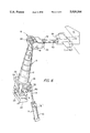
FIG. 7 shows in even greater detail the construction of the upper joint 16. The upper telescoping segment 13 is secured to fixed yoke 36. The swinging yoke 29 rotates about the fixed yoke 36 when the rotary actuator 28 is powered by hydraulic motor 40. In order to precisely stop the upper joint at a preselected position, a normally closed hydraulic brake 42 is released.
A power gear train exists between the hydraulic motor 40 and the rotary actuator 28. A simplified gear train is indicated by individual gears 46 and 48, the latter being contained within the swinging yoke 29. A position potentiometer 38 is mechanically linked to the power gear train for measuring the degree of angular orientation of the upper joint 16. A number of the latter-mentioned components are diagrammatically shown by dotted lines in FIG. 7 and are not shown or discussed in detail since the joint is a conventional mechanism as employed to position aircraft flaps.
Whereas the hydraulic motor 40 furnishes power to rotate the upper joint 16, the hydraulic motor 50, shown in FIG. 6, powers a conventional screw member within the telescoping mechanism 8 for extending the telescoping segments as required. A conventional positional sensor 52 detects the degree of telescoping column extension. Hydraulic power components instead of electrical components are used to avoid interference with electronic measurements.
Control of the hydraulic motors 40, 50 and hydraulic cylinder 10 is achieved by conventional microprocessor control. Since such techniques are well-established in the art, they will not be shown or described in this specification. However, it should be noted that kinimatic equations are stored in memory and solved ten times a second to coordinate the various rotational and linear displacements for the telescoping column, upper joint and turntable, as functions of desired model yaw and pitch angle.
Thus, from the above-described invention, it will be appreciated that the present invention offers a plane model positioning mechanism which is capable of continuously and accurately varying yaw and pitch angle so as to precisely simulate desired model positions within a wind tunnel.
It should be understood that the invention is not limited to the exact details of construction shown and described herein for obvious modifications will occur to persons skilled in the art.

Claims (3)

We claim:
1. A wind tunnel model movable support comprising:
a telescoping column;
hydraulic means connected to the column enabling pivoting of the column about an axis passing through its base;
a joint connected to a top segment of the column for rotation about an axis perpendicular to the column;
a sting connected at a first end thereof to the joint while a second end of the sting is secured to the model;
hydraulic means connected to the column for varying the length thereof;
hydraulic means for rotating the joint; and
a turntable for supporting the column thereon;
wherein coordinated continuous movement of the joint and column in a plane results in corresponding continuous first angle change of a model about a rotational axis fixed in space; and
further wherein turntable rotation varies the orientation of the model about a second axis.
2. The structure set forth in claim 1 wherein the sting supports the model in a horizontal wing orientation whereby the first angle is pitch angle and the second angle is yaw angle.
3. The structure set forth in claim 1 wherein the sting supports the model in a vertical wing orientation whereby the first angle is yaw angle and the second angle is pitch angle.
US07/530,295 1990-05-30 1990-05-30 Wind tunnel model positioning device Expired - Fee Related US5020364A (en)

Priority Applications (1)

Application Number Priority Date Filing Date Title
US07/530,295 US5020364A (en) 1990-05-30 1990-05-30 Wind tunnel model positioning device

Applications Claiming Priority (1)

Application Number Priority Date Filing Date Title
US07/530,295 US5020364A (en) 1990-05-30 1990-05-30 Wind tunnel model positioning device

Publications (1)

Publication Number Publication Date
US5020364A true US5020364A (en) 1991-06-04

Family

ID=24113135

Family Applications (1)

Application Number Title Priority Date Filing Date
US07/530,295 Expired - Fee Related US5020364A (en) 1990-05-30 1990-05-30 Wind tunnel model positioning device

Country Status (1)

Country Link
US (1) US5020364A (en)

Cited By (25)

* Cited by examiner, † Cited by third party
Publication number Priority date Publication date Assignee Title
US5345818A (en) * 1993-06-25 1994-09-13 Georgia Tech Research Corporation Wind driven dynamic manipulator for a wind tunnel
US5696319A (en) * 1996-09-06 1997-12-09 Mcdonnell Douglas Corporation Flexure fixture for dynamic loading modal surveys of test articles
DE19815312C1 (en) * 1998-04-06 1999-11-18 Daimler Chrysler Ag Method and device for precise positioning, in particular of a vehicle, in a wind tunnel
US20030000298A1 (en) * 2000-11-06 2003-01-02 Heisler Richard R. Rapid prototype wind tunnel model and method of making same
US20040187563A1 (en) * 2002-03-26 2004-09-30 Fleming Ronald J. Flow vector analyzer for flow bench
US20040253107A1 (en) * 2002-11-13 2004-12-16 Mark Page Positioning system for wind tunnel and method of use
US20060021427A1 (en) * 2002-03-25 2006-02-02 Fleming Ronald J Flow stabilizer for flow bench
US20070095135A1 (en) * 2005-10-31 2007-05-03 The Boeing Company Method for determining drag characteristics of aircraft and system for performing the method
WO2009013325A1 (en) * 2007-07-26 2009-01-29 Eads Deutschland Gmbh Test arrangement having a test model and a fastening apparatus, wind tunnel arrangement, and such a fastening apparatus
US20090166475A1 (en) * 2007-12-27 2009-07-02 Airbus Deutschland Gmbh Apparatus for the pivotal fastening of an active surface, in particular a spoiler on a wind tunnel model of an aircraft
US7997130B1 (en) * 2009-03-27 2011-08-16 The Boeing Company System and method for measuring deformation of an object in a fluid tunnel
US20120125091A1 (en) * 2010-11-19 2012-05-24 Lockheed Martin Corporation Aerodynamic Testing Method and Apparatus
CN103018000A (en) * 2012-12-31 2013-04-03 中国人民解放军国防科学技术大学 Wind tunnel three-degree-of-freedom model posture adjustment device
CN103033336A (en) * 2013-01-14 2013-04-10 中国航空工业集团公司沈阳飞机设计研究所 High speed wind tunnel supporting system
CN103057728A (en) * 2012-12-24 2013-04-24 中国航空工业集团公司沈阳空气动力研究所 Achievement device of airplane model test gestures
CN104458197A (en) * 2014-11-14 2015-03-25 扬州大学 Wind tunnel testing model supporting mechanism based on parallelogram mechanism
US9134195B1 (en) * 2013-01-03 2015-09-15 The Boeing Company Methods and systems for enabling wind tunnel models to transition between measuring aerodynamic forces and measuring acoustic signatures
CN105527067A (en) * 2015-11-27 2016-04-27 湖北三江航天红峰控制有限公司 Rubber sheet angle deflecting and locking device
CN105910792A (en) * 2016-05-31 2016-08-31 中国航空工业集团公司西安飞机设计研究所 Airplane wind tunnel test model installation device
CN105910791A (en) * 2016-05-31 2016-08-31 中国航空工业集团公司西安飞机设计研究所 Airplane wind tunnel test model installation device
CN107525647A (en) * 2017-07-26 2017-12-29 北京航空航天大学 A kind of dynamical bifurcation generating means of aerodynamic stalling
RU179254U1 (en) * 2017-11-08 2018-05-07 Федеральное государственное унитарное предприятие "Центральный аэрогидродинамический институт имени профессора Н.Е. Жуковского" (ФГУП "ЦАГИ") Electromechanical stand
CN109342009A (en) * 2018-11-12 2019-02-15 中国空气动力研究与发展中心高速空气动力研究所 A kind of high-aspect-ratio aircraft model in wind tunnel fidelity shape double-vane supporting mechanism and its application
CN111044254A (en) * 2019-12-09 2020-04-21 中国航天空气动力技术研究院 Flat-rudder local model device for realizing multi-attitude simulation
CN113753261A (en) * 2021-11-09 2021-12-07 中国空气动力研究与发展中心低速空气动力研究所 Wind tunnel test device and method for combined model of combined conventional rotor wing high-speed helicopter

Citations (3)

* Cited by examiner, † Cited by third party
Publication number Priority date Publication date Assignee Title
US4547119A (en) * 1981-10-23 1985-10-15 United States Robots, Inc. Robotic manipulator arm
US4658635A (en) * 1985-03-13 1987-04-21 Deutsche Forschungs- Und Versuchsanstalt Simulator for aerodynamic investigations of models in a wind tunnel
US4862739A (en) * 1988-06-16 1989-09-05 Rockwell International Corporation Wind tunnel model support mechanism

Patent Citations (3)

* Cited by examiner, † Cited by third party
Publication number Priority date Publication date Assignee Title
US4547119A (en) * 1981-10-23 1985-10-15 United States Robots, Inc. Robotic manipulator arm
US4658635A (en) * 1985-03-13 1987-04-21 Deutsche Forschungs- Und Versuchsanstalt Simulator for aerodynamic investigations of models in a wind tunnel
US4862739A (en) * 1988-06-16 1989-09-05 Rockwell International Corporation Wind tunnel model support mechanism

Cited By (38)

* Cited by examiner, † Cited by third party
Publication number Priority date Publication date Assignee Title
US5345818A (en) * 1993-06-25 1994-09-13 Georgia Tech Research Corporation Wind driven dynamic manipulator for a wind tunnel
US5696319A (en) * 1996-09-06 1997-12-09 Mcdonnell Douglas Corporation Flexure fixture for dynamic loading modal surveys of test articles
DE19815312C1 (en) * 1998-04-06 1999-11-18 Daimler Chrysler Ag Method and device for precise positioning, in particular of a vehicle, in a wind tunnel
US20030000298A1 (en) * 2000-11-06 2003-01-02 Heisler Richard R. Rapid prototype wind tunnel model and method of making same
US6796171B2 (en) 2000-11-06 2004-09-28 The Johns Hopkins University Rapid prototype wind tunnel model and method of making same
US20060021427A1 (en) * 2002-03-25 2006-02-02 Fleming Ronald J Flow stabilizer for flow bench
US7024929B2 (en) 2002-03-25 2006-04-11 Fleming Ronald J Flow stabilizer for flow bench
US6923051B2 (en) * 2002-03-26 2005-08-02 Ronald J. Fleming Flow vector analyzer for flow bench
US20040187563A1 (en) * 2002-03-26 2004-09-30 Fleming Ronald J. Flow vector analyzer for flow bench
US20040253107A1 (en) * 2002-11-13 2004-12-16 Mark Page Positioning system for wind tunnel and method of use
US6962076B2 (en) * 2002-11-13 2005-11-08 Swift Engineering, Inc. Positioning system for wind tunnel and method of use
US20070095135A1 (en) * 2005-10-31 2007-05-03 The Boeing Company Method for determining drag characteristics of aircraft and system for performing the method
US7254998B2 (en) * 2005-10-31 2007-08-14 The Boeing Company Method for determining drag characteristics of aircraft and system for performing the method
WO2009013325A1 (en) * 2007-07-26 2009-01-29 Eads Deutschland Gmbh Test arrangement having a test model and a fastening apparatus, wind tunnel arrangement, and such a fastening apparatus
DE102007035464A1 (en) * 2007-07-26 2009-01-29 Eads Deutschland Gmbh Experimental arrangement with a test model and a fastening device, wind tunnel arrangement and such a fastening device
US8245977B2 (en) * 2007-12-27 2012-08-21 Airbus Operations Gmbh Apparatus for the pivotal fastening of an active surface, in particular a spoiler on a wind tunnel model of an aircraft
US20090166475A1 (en) * 2007-12-27 2009-07-02 Airbus Deutschland Gmbh Apparatus for the pivotal fastening of an active surface, in particular a spoiler on a wind tunnel model of an aircraft
US7997130B1 (en) * 2009-03-27 2011-08-16 The Boeing Company System and method for measuring deformation of an object in a fluid tunnel
US20120125091A1 (en) * 2010-11-19 2012-05-24 Lockheed Martin Corporation Aerodynamic Testing Method and Apparatus
US8316701B2 (en) * 2010-11-19 2012-11-27 Lockheed Martin Corporation Aerodynamic testing method and apparatus
CN103057728B (en) * 2012-12-24 2015-09-02 中国航空工业集团公司沈阳空气动力研究所 A kind of model aircraft test attitude implement device
CN103057728A (en) * 2012-12-24 2013-04-24 中国航空工业集团公司沈阳空气动力研究所 Achievement device of airplane model test gestures
CN103018000A (en) * 2012-12-31 2013-04-03 中国人民解放军国防科学技术大学 Wind tunnel three-degree-of-freedom model posture adjustment device
US9134195B1 (en) * 2013-01-03 2015-09-15 The Boeing Company Methods and systems for enabling wind tunnel models to transition between measuring aerodynamic forces and measuring acoustic signatures
CN103033336A (en) * 2013-01-14 2013-04-10 中国航空工业集团公司沈阳飞机设计研究所 High speed wind tunnel supporting system
CN103033336B (en) * 2013-01-14 2015-04-01 中国航空工业集团公司沈阳飞机设计研究所 High speed wind tunnel supporting system
CN104458197A (en) * 2014-11-14 2015-03-25 扬州大学 Wind tunnel testing model supporting mechanism based on parallelogram mechanism
CN104458197B (en) * 2014-11-14 2017-09-01 扬州大学 A kind of model in wind tunnel supporting mechanism based on parallel-crank mechanism
CN105527067B (en) * 2015-11-27 2018-07-24 湖北三江航天红峰控制有限公司 A kind of device for the angular deflection of rudder piece and locking
CN105527067A (en) * 2015-11-27 2016-04-27 湖北三江航天红峰控制有限公司 Rubber sheet angle deflecting and locking device
CN105910792A (en) * 2016-05-31 2016-08-31 中国航空工业集团公司西安飞机设计研究所 Airplane wind tunnel test model installation device
CN105910791A (en) * 2016-05-31 2016-08-31 中国航空工业集团公司西安飞机设计研究所 Airplane wind tunnel test model installation device
CN107525647A (en) * 2017-07-26 2017-12-29 北京航空航天大学 A kind of dynamical bifurcation generating means of aerodynamic stalling
RU179254U1 (en) * 2017-11-08 2018-05-07 Федеральное государственное унитарное предприятие "Центральный аэрогидродинамический институт имени профессора Н.Е. Жуковского" (ФГУП "ЦАГИ") Electromechanical stand
CN109342009A (en) * 2018-11-12 2019-02-15 中国空气动力研究与发展中心高速空气动力研究所 A kind of high-aspect-ratio aircraft model in wind tunnel fidelity shape double-vane supporting mechanism and its application
CN109342009B (en) * 2018-11-12 2020-03-31 中国空气动力研究与发展中心高速空气动力研究所 High-aspect-ratio airplane wind tunnel test model fidelity appearance double-wing supporting mechanism and application thereof
CN111044254A (en) * 2019-12-09 2020-04-21 中国航天空气动力技术研究院 Flat-rudder local model device for realizing multi-attitude simulation
CN113753261A (en) * 2021-11-09 2021-12-07 中国空气动力研究与发展中心低速空气动力研究所 Wind tunnel test device and method for combined model of combined conventional rotor wing high-speed helicopter

Similar Documents

Publication Publication Date Title
US5020364A (en) Wind tunnel model positioning device
WO2020093577A1 (en) Laser scanning attitude angle stabilization method and apparatus for helicopter-borne lidar
CN111591462B (en) Helicopter tail rotor simulation system for wind tunnel test
FR2530357B1 (en)
JPS5858841B2 (en) antenna equipment
US5811673A (en) Wind direction indicator
KR20120135051A (en) Resolver type skew sensor with gimbal attachment
CA1070106A (en) Method and apparatus for leveling an instrument in a well bore
US5117690A (en) Wind speed and wind direction indicator
CN2669181Y (en) Rotay target mark capable of changing analogue object space angle
CN109506089A (en) A kind of balance and stability device and application method supporting high speed rotation camera
CN108275282A (en) A kind of air-ground complementary remote sensing survey device
CA2186902A1 (en) Positioning Apparatus for Inertial Sensors
JPH0366199B2 (en)
US3008525A (en) Rotor blade installation means and method
CN208021772U (en) A kind of air-ground complementary remote sensing survey device
CN209587505U (en) A kind of balance and stability device supporting high speed rotation camera
CN113324699A (en) Aircraft inertia measures gesture adjusting device
CN108344427B (en) Calibration method and calibration mechanism for pitching reflector of star sensor
JPS60210793A (en) Regulator for angle of precision apparatus
RU811983C (en) Device for measuring model angle of incidence
EP0398150A3 (en) Attitude sensing apparatus
JPS5841279B2 (en) Metal wheel with automatic correction device
US3163935A (en) Mechanical coordinate converter
US20040262489A1 (en) Adjustable mounting mechanism capable of pan, tilt, roll and their combinations

Legal Events

Date Code Title Description
AS Assignment

Owner name: GRUMMAN AEROSPACE CORPORATION, A CORP. OF NY, NEW

Free format text: ASSIGNMENT OF ASSIGNORS INTEREST.;ASSIGNORS:MANITT, PHILIP J.;THOMAS, VINCENT F.;MCALLISTER, WILLIAM J.;REEL/FRAME:005332/0463

Effective date: 19900523

CC Certificate of correction
FEPP Fee payment procedure

Free format text: PAYOR NUMBER ASSIGNED (ORIGINAL EVENT CODE: ASPN); ENTITY STATUS OF PATENT OWNER: LARGE ENTITY

FPAY Fee payment

Year of fee payment: 4

FEPP Fee payment procedure

Free format text: PAYER NUMBER DE-ASSIGNED (ORIGINAL EVENT CODE: RMPN); ENTITY STATUS OF PATENT OWNER: LARGE ENTITY

Free format text: PAYOR NUMBER ASSIGNED (ORIGINAL EVENT CODE: ASPN); ENTITY STATUS OF PATENT OWNER: LARGE ENTITY

REMI Maintenance fee reminder mailed
LAPS Lapse for failure to pay maintenance fees
FP Lapsed due to failure to pay maintenance fee

Effective date: 19990604

STCH Information on status: patent discontinuation

Free format text: PATENT EXPIRED DUE TO NONPAYMENT OF MAINTENANCE FEES UNDER 37 CFR 1.362