US5017876A - Corona current monitoring apparatus and circuitry for A.C. air ionizers including capacitive current elimination - Google Patents
Corona current monitoring apparatus and circuitry for A.C. air ionizers including capacitive current elimination Download PDFInfo
- Publication number
- US5017876A US5017876A US07/428,604 US42860489A US5017876A US 5017876 A US5017876 A US 5017876A US 42860489 A US42860489 A US 42860489A US 5017876 A US5017876 A US 5017876A
- Authority
- US
- United States
- Prior art keywords
- signal
- current
- corona
- capacitive
- corona current
- Prior art date
- Legal status (The legal status is an assumption and is not a legal conclusion. Google has not performed a legal analysis and makes no representation as to the accuracy of the status listed.)
- Expired - Lifetime
Links
Images


Classifications
-
- G—PHYSICS
- G01—MEASURING; TESTING
- G01R—MEASURING ELECTRIC VARIABLES; MEASURING MAGNETIC VARIABLES
- G01R19/00—Arrangements for measuring currents or voltages or for indicating presence or sign thereof
- G01R19/0046—Arrangements for measuring currents or voltages or for indicating presence or sign thereof characterised by a specific application or detail not covered by any other subgroup of G01R19/00
- G01R19/0061—Measuring currents of particle-beams, currents from electron multipliers, photocurrents, ion currents; Measuring in plasmas
Definitions
- This invention relates to A.C. air ionizers, and more particularly relates to electrical apparatus and circuitry for measuring corona current in the ion stream being emitted from the discharging electrodes of such air ionizers in order to evaluate the efficiency thereof at any time.
- Corona discharge electrodes operating on alternating current are utilized in a variety of air ionizing devices for generating both positive and negative ions, such as static eliminators or neutralizers, corotrons of electrostatic copiers, electrostatic precipitators, and the like.
- Typical electrical A.C. air ionizing devices are driven by high voltages ranging from about 3,000 volts to 10,000 volts at frequencies from about 50 Hz to 20 KHz by means of a high voltage transformer whose output is coupled to one or more sharp electrodes in the form of points or small diameter wire positioned in the proximity of ground.
- Corona current is only generated when the voltage on the discharge electrodes exceeds the corona onset level, and there is no corona current when the point voltage is below that threshold.
- the average corona current for a given corona electrode is a function of the voltage applied to the corona electrode.
- FIG. 1 A typical wave form for total current (capacitive current plus corona current) with respect to time is shown in FIG. 1, the capacitive (or displacement) current which is substantially sinusoidal in configuration being always present during operation and 90° out of phase with the A.C. voltage applied to the discharge electrodes.
- the corona current When the voltage applied to the discharge electrode exceeds the corona threshold level, the corona current will start flowing and continue to flow until the voltage on the electrode decreases below the threshold level.
- the pulse of corona current normally begins about the time that the sinusoidal waveform of the displacement or capacitive current reaches its peak value.
- the corona threshold or onset level is a function of the sharpness of the discharge electrode points, their distance from a proximity ground, the atmosphere of operation, and the degree of contamination of such discharge electrodes.
- corona electrodes tend to attract contamination from the environment, especially dust. As the electrodes become covered with contamination, their corona characteristics change--usually, the corona current diminishes, and the air ionizers become less efficient so as to become ultimately ineffective. This condition is quite difficult to detect, particularly in the case of air ionizers where a strong signal generated by the field from the corona electrodes via the capacitance of the air masks the signal generated by the ion flow itself.
- a detector screen is interposed in the ion path within the housing at the ion exit port for the purpose of capturing some of the ions produced by the electrodes.
- the detection screen is of conductive material and held at virtually ground level by means of a low impedance operational amplifier circuit.
- a similar screen coupled directly to ground is positioned between the ion generating electrodes and the detection screen in order to terminate the electric field lines emanating from the electrodes.
- Another object of this invention is to provide an air ionizer having means for separating the corona current from the total current (i.e. corona or ionization current plus capacitive or displacement current) and monitoring this corona current as a function of the efficiency of the ionizer output.
- Yet another object of this invention is to provide a means for determining the efficiency of an air ionizer at any time without materially intruding upon the production of air ions.
- the present invention there is provided a method for separating the corona current component from the capacitive current component in the total ground plane current of the A.C. ionizing device, the total ground plane current being generally the sum of the corona current and capacitive current at any time.
- the wave form for the total current with respect to the ground plane is shown in FIG. 1.
- the corona current component When the corona current component is isolated, it may be continuously measured and its level monitored for the purpose of assessing the efficiency of the air ionizer.
- the capacitive current signal is derived directly either by obstructing the flow of corona current being generated by one discharge electrode to a sensing element or by entirely preventing (squelching) the generation of corona current by one discharge electrode or a portion thereof with respect to a sensing element.
- Corona current to a sensing element may be blocked or disrupted by encapsulating said sensing element in an insulative coating.
- the generation of corona current may be entirely inhibited in connection with a discharge electrode by increasing the radius of curvature of the tip of such an electrode to the extent that at the high voltage imposed thereon breakdown of the air gap does not occur or by incorporating an insulative layer about such an electrode to the same effect.
- a pair of sensors are adjacently spaced with respect to one of the discharge electrodes, and each sensing element is coupled to opposing inputs of a differential amplifier.
- one sensor is insulated to disrupt the flow of corona current thereto, thus delivering a signal which is representative of just capacitive current (i.e. corona current to that electrode being obstructed).
- the other electrode is uninsulated and thereby provides a signal representing the total ground plane current at any time (i.e. capacitive current in addition to ionizing current when corona is effected).
- the differential amplifier provides an output signal that is proportional to just the corona current which upon rectification is a measure thereof.
- first mode involves the squelching of the corona current at the electrode being monitored, the discharge electrode being so constructed and arranged so as not to generate any corona current at all toward one sensing element. Neither of the pair of sensing elements employed is insulated.
- the point of one discharge electrode has a radius of curvature sufficiently large as to prevent the generation of corona current therefrom so that the sensing element adjacent thereto delivers a signal which is proportional to just capacitive current.
- the other sensing element is adjacently spaced from a normal pointed electrode and provides a signal representing the total ground plane current at any time.
- each of the sensing elements is coupled to opposing inputs of a differential amplifier and the output signal therefrom is proportional to corona current alone which upon rectification is a measure of the corona current.
- the point of the electrode which is being monitored for capacitive current is encapsulated within an insulative covering whereby at the high voltage imposed no corona current is generated, the pair of sensing elements again being input to a differential amplifier that subtracts the capacitive current signal from the total current signal such that an output signal proportional to corona current is produced.
- a pair of conductive sensing elements are longitudinally spaced from each other along the axis of the wire.
- One sensing element encircles an insulated portion of the wire in suppression of corona current while the second sensing element encircles an uninsulated portion of the wire and monitors the total of capacitive and corona current.
- a single sensor adjacently spaced from one discharge electrode is directly coupled to one input of a differential amplifier to provide a measure of the total current while a second input of the differential amplifier is coupled to the A.C. line voltage through an electronic circuit which by way of appropriate phase adjustment and attenuation generates a signal equal to the capacitive current in the total current signal.
- the electronic circuit includes a capacitance and resistance network for attenuating the capacitive current signal and adjusting the phase thereof until it is equal to the capacitive current component obtained from the first sensor. Subtraction of the capacitive current from the total current by means of the differential amplifier will as before provide an A.C. corona current signal at the output of said differential amplifier which upon rectification again produces a D.C. current signal proportional to the corona current.
- a single sensor is adjacently spaced from a single discharge electrode and the total current signal therefrom (capacitive plus corona current at any time) is applied to the input of a phase discriminator so adjusted to pass a selective portion of each cycle of said total current signal.
- a phase discriminator so adjusted to pass a selective portion of each cycle of said total current signal.
- the selected signal portion is a 180° portion of the cycle lying intermediate each consecutive pair of such corresponding positive and negative peaks (or alternatively, adjacent negative and positive peaks) of the capacitive current signal wave form and having a zero average capacitive current component
- the signal passed will contain the entire positive (or negative) corona current component.
- the capacitive current component will cancel itself out so that the resultant D.C. signal output in this case will be actually proportional to positive (or negative corona) current.
- the respective positive or negative corona current monitored in a measure of the corona current emitted by the A.C. air ionizer.
- the selected portion of the signal waveform will contain a fractional part of the positive (or negative, whichever is the case) corona current component so that the resultant D.C. signal after filtering will be related to the corresponding positive or negative corona current and be a measure of the corona current level of the A.C. air ionizer.
- FIG. 1 is a graphical representation of the prior art wave form with respect to time for total electrode current of a typical A.C. air ionizer.
- FIG. 2 is a schematic circuit diagram of a first embodiment of this invention wherein corona current of an A.C. air ionizer is monitored by detecting total current of one discharge electrode and then, after directly measuring the capacitive current component, electrically subtracting the capacitive current from the total current.
- FIG. 3 is a schematic circuit diagram of another embodiment of this invention in which the capacitive current component of total current of an A.C. air ionizer is directly detected prior to electrically subtracting the capacitive current signal from the total current.
- FIG. 4 is a schematic circuit diagram of yet another embodiment of this invention in which the capacitive current component of total current is directly detected prior to electrical subtraction.
- FIG. 5 is a schematic circuit diagram of still another embodiment of this invention for directly detecting the capacitive current component of total current in an A.C. air ionizer having a continuous wire discharge electrode.
- FIG. 6 is a schematic circuit diagram of a yet still another embodiment of this invention wherein a capacitive current signal equal to the capacitive current component of total current is generated by independent electronic circuitry coupled to the A.C. voltage operating the A.C. air ionizer.
- FIG. 7 is a graphical representation of the corona current signal appearing at the output of the differential amplifier for the various embodiments of this invention shown in FIGS. 2 through 6.
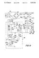
- FIG. 8 is a schematic diagram illustrative of a further embodiment of the present invention wherein phase discriminator circuitry is utilized to isolate the corona current component from the total current.
- FIG. 9 is a graphical representation of a signal with respect to time appearing at the output of the phase discriminator configured to isolate the positive corona current.
- FIG. 10 is a graphical representation of a signal with respect to time appearing at the output of the phase discriminator configured to isolate the negative corona current.
- a corona current monitor having sensing means B adapted to isolate the corona current emitted at the air ionizer discharge electrodes from the capacitive or displacement current imposed on said electrode by an A.C. high voltage power source.
- the air ionizer A may be any static eliminator or neutralizer, corotron or electrostatic precipitator in which one or more discharge electrodes 10 are adjacently spaced from a conductive casing 12, normally at ground potential, and across which is coupled a high voltage A.C. power source 14 so as to cause emission of positive and negative ions in he air gap therebewteen.
- the discharge electrodes 10 are usually in the form of conductive tapered pins or pointed needles, but can be made of thin diameter longitudinally extending wire, or short lengths of snipped wire, sharp blades or a plurality of brush bristles, or the like. Examples of various types of static eliminators are shown in U.S. Pat. Nos.
- the A.C. power supply 14 generally consists of a high voltage transformer having a secondary output in the range of 3,000 to 15,000 volts at frequencies of from about 50 Hz to 20 KHz.
- the ground member 12 may be a conductive housing which partially surrounds the electrodes 10 or may be a proximity ground when no casing is employed.
- the wave form of the current follows the voltage curve by 90° and exhibits a configuration substantially identical to the applied voltage, usually sinusoidal, but having pips or blips at the positive and negative crests thereof (the latter defining the ionizing or corona current when the corona onset or threshold is exceeded).
- a representation of a typical total current versus time curve at the discharge electrodes 10 for a conventional air ionizer is shown in FIG. 1.
- the capacitive current and corona current are basically 90° out of phase, the total ground plane current being generally the sum of the corona current and the capacitive current.
- the broken lines depict the capacitive current component of a total current signal.
- one embodiment of the sensor B for isolating or separating the corona current from the capacitive or displacement current comprises a pair of conductive elements 16 and 18, each being substantially half-toroidal in shape (one-half of a doughnut) and adjacently spaced around the point of one of the air ionizer electrodes 10.
- the sensing elements 16 and 18 are parts of a ring so that all portions thereof are equidistant from the locus of the point, these elements may also be plates or disks.
- a preferred spacing of the sensing elements 16 and 18 from the points 10 should be a distance of from about 2 mm to 20 mm.
- the sensing element 16 is directly coupled to one input (positive) of a differential amplifier 20 across a resistor R2, for example.
- the element 18 is encapsulated within an insulating covering 22, and is coupled directly to the (negative) input of differential amplifier 20 across resistor R1, the insulation 22 being sufficient to prevent corona current from passing from the point 10 to sensing element 18.
- the signal voltage produced by the capacitive current across R1 is in effect a function of pure displacement current.
- the voltage across resistor R2 will be a function of the sum total of capacitive current plus corona current.
- resistors R1, R2 and feedback resistor R are selected in a manner well known to those skilled in the art so as to generate appropriate operating signal voltages in connection with the differential amplifier 20.
- a typical corona current wave form from the differential amplifier 20 is illustrated graphically in FIG. 7. When rectified and filtered and monitored in a conventional manner, such signal is a measure of such corona current.
- FIG. 3 there is shown another embodiment of the instant invention wherein instead of blocking the flow of corona current to the capacitive current monitoring sensor 18 by means of insulation 22, the electrode being monitored is so constructed and arranged as to prevent entirely the generation of any corona whatsoever from such electrode when high voltage is applied to the air ionizer A.
- electrode 10A has a spherical tip of sufficiently large radius of curvature as will effectively squelch any corona emission at all therefrom.
- An uninsulated conductive sensor B1 in the form of a ring encircles pointed discharge electrode 10 while a second ring-shaped uninsulated conductive sensor B2 is concentrically about the spherically configured discharge electrode 10A.
- the sensing element B1 oriented about the pointed electrode 10 detects the total current of said electrode, which includes both corona current as well as capacitive current, and applies a first signal input to a differential amplifier 20.
- the sensing element B2 encircling the spherical electrode 10A with respect to which no corona current is emitted since it is non-corona-generating, provides a signal that is a measure of merely the capacitive current component alone.
- the latter signal is applied as the second input to the differential amplifier, electrical subtraction of the capacitive current signal from the total current signal produces at the output thereof a signal proportional to corona current alone.
- FIG. 4 there is shown another embodiment of the first mode of this invention wherein an electrode having an insulated tip 10B is inhibited from emitting corona as the high voltage is applied to the air ionizer A.
- Ring sensor B2 encircling the insulated electrode 10B does not pick up any corona current signal since corona is effectively prevented by the squelching action of the insulation as the A.C. ionizer high voltage is applied to this insulated electrode. Therefore, ring sensor B2 detects a signal proportional to the capacitive current component alone.
- Ring sensor B1 concentrically spaced about the point of corona emitting discharge electrode 10 provides a signal that is the sum of both the capacitive and corona current components. Accordingly, when the total current signal from sensor B1 and the capacitive current signal from sensor B2 are applied as opposing inputs to the differential amplifier, the electrically subtracted output is again a measure of corona current alone.
- FIG. 5 there is shown an air ionizer employing a continuous fine wire element 10C as the discharging electrode.
- a pair of conductive ring-shaped sensing elements B1 and B2 are axially spaced from each other in concentric disposition about the wire electrode 10C.
- One of the ring sensors B2 encircles an insulated portion 19 covering the wire electrode 10C such that the insulation sheath 19 prevents any corona from being generated underneath the encircling sensing element B2 whereby said sensor detects only the capacitive current component at the underlying insulated portion.
- the ring sensor B1 surrounding the portion of the wire 10C which is uninsulated provides a first input to the differential amplifier which is a measure of total current while the sensor B2 encircling the insulated covering 19 about the wire 10C furnishes a second input which is a measure of just the capacitive current component. Electrically subtracting the two signals via the differential amplifier yields an output which is again proportional to the corona current component.
- FIG. 6 we show another mode of the instant invention wherein rather than directly picking off the capacitive current signal by means of a sensing element, a signal equal to the capacitive current component of the total current is independently generated by coupling one input of a differential amplifier 30 through electrical circuitry to the A.C. line voltage.
- the electrical circuitry for generating the capacitive current signal constitutes a direct or capacitive connection to the A.C. line voltage by way of capacitor 28 and phase adjusting network comprising capacitor C p and adjustable potentiometer TP p .
- Potentiometer 32 provides attenuation of the signal whereby it is equal to the capacitive current component of the total current detected by sensor B1.
- the sensor B1 is again in the form of an uninsulated conductive ring entirely encircling one of the air ionizer discharge electrodes 10. This sensing element B1 as in the case of the first mode detects the total of both capacitive as well as corona current.
- the signal from the ring sensor B1 is applied to the negative input of a TL081 integrated circuit hooked up as an differential amplifier 30 while the generated capacitive current signal is coupled to the positive input of amplifier 30.
- the differential amplifier 30 will null the capacitive signal and provide an output signal which is again proportional to corona current.
- the output wave form of the differential amplifier 30 which electrically substracts the independently generated capacitive signal input from the total current signal input detected by sensor B1 is also shown in FIG. 7. This wave form is the same as the output wave forms from differential amplifier 30 which electrically subtracted the directly detected capacitive current signal from the sensed total current signal input produced by the embodiments set forth in FIGS. 2, 3, 4 and 5.
- the transient corona signal can be rectified through diode circuit 34 and applied to the (-) input of comparator 36, the other input to which can be controlled by adjusting the threshold that activates visual indicator 38 when corona current falls below a predetermined level.
- capacitive current is a function of the capacitance of an ionizing electrode to ground, its value can be treated as a constant for all practical purpose. Since the capacitive signal can be picked up through a capacitive coupling, and adjusted to the proper phase and amplitude by C p and TP p , it is not necessary to employ any sensor whatsoever to monitor the capacitive current component in a shockless type static eliminator, for example, as shown in U.S. Pat. No. 3,156,847, wherein each of the discharge electrodes is capacitively connected to the high voltage through a capacitance.
- a third mode of this invention isolates the corona current from the capacitive current by means of a phase discriminator circuit 45 (indentified by the portions of the circuit enclosed within dashed lines). In this arrangement, separation is accomplished without directly measuring the capacitive current as a separate component through use of one of the sensor embodiments, as shown in FIGS. 2 and 5 or without separately generating a capacitive current signal, as shown in FIG. 6.
- a single sensor B3 utilizing a ring-shaped element 42 applies a total current signal (i.e.--the sum of the capacitive and corona current components) to the input of the phase discriminator.
- the phase discriminator 45 passes only a portion of the signal with respect to time, namely that portion of each full cycle of the total current signal which contains equal positive and negative segments of the capacitive current component so that the average capacitive current signal equals zero.
- the capacitive current signal wave will be caused to cancel itself out and leave only that component proportional to corona current remaining.
- the D.C. signal will primarily contain and be proportional to positive corona current. See FIG. 9.
- the D.C. signal will primarily contain and be proportional to negative corona current, as shown in FIG. 10.
- the corona current component is filtered by way of an R-C network (comprising 10K resistor R4 and 10 microfarad condenser C6), to produce a D.C. signal proportional to corona current. This D.C. level across capacitor C6 is applied to the negative input of comparator 52.
- (+) and (-)12 volt supply voltages for the various amplifiers and circuit components are developed by coupling 115 volt A.C. line voltage across center tapped step-down transformer 54 whose secondary is applied to full wave diode rectifier 56.
- the A.C. voltage at the secondary of the transformer 54 is also used as a timing signal in the operation of the phase discriminator circuit 45 by applying a portion of said voltage to the input of operational amplifier 58.
- the current sensed by ring sensor element 42 is delivered to the positive input of operational amplifier 60 which is connected as a voltage follower.
- the portion of the signal passed through the phase discriminator is determined by the state of a field effect transistor (FET) 62, which state is controlled by the signal applied to its gate.
- FET field effect transistor
- This signal is generated by the output of comparator 58 which compares the voltage at the secondary of transformer 54 with respect to the voltage at the positive input terminal of op amp 58.
- the duty cycle of this signal can be varied by applying different bias to the positive input of opamp 58 via variable resistor R13.
- the phase relationship between the signal derived from the voltage follower 60 and the signal at the gate of FET 62 can be adjusted by variable resistor 65 to obtain a null of the D.C. signal attributed to the capacitive current component.
- the D.C. signal is measured at the R-C filter 50 consisting of resistor R4 and capacitor C6.
- the signal to the gate of the FET 62 (acting as a chopper) can be reversed by connecting the resistor R9 to the other side of the secondary of transformer 54.
- the output of comparator 52 actuates either a red LED 64 or a green LED 66 to indicate the status of the D.C. voltage at the negative input to said comparator.
- the LED indication When the output voltage across capacitor C6 goes below a predetermined threshold level determined by the resistance divider R5 and R7, the LED indication will change from green to red, the comparator ratio being adapted to be modified to provide any desired level.
- a meter (not shown) can be connected across the condenser C6 to give a visual indication of the corona current level.
- the cross hatched areas of the curves in FIGS. 9 and 10 designate the recurring signals which, after filtering, will provide the respective positive or negative D.C. signals proportional to corona current.
- the phase discriminator circuit 45 which is coupled to the signal sensor B3 is so constructed and arranged as to pass just a selected portion of each full cycle of the A.C. total signal detected by said sensor. If an appropriate portion is passed through, the capacitive current component will cancel itself out and leave only an A.C. signal component related to corona current. It is necessary to select either one of the positive or negative current pulses in order to obtain a measure of what the corona current actually is.
- the resulting D.C. signal will be related to positive corona current.
- the filtered D.C. signal will be a measure of negative corona current.
- the portion of the signal passed by the phase discriminator 45 is selected to be a 180° portion of the cycle lying between adjacent positive and negative peaks (or alternatively, corresponding negative and positive peaks) and having a zero average capacitive current component
- the selected portion of the signal waveform will contain an entire positive (or negative) corona component.
- the resultant D.C. signal will be proportional to positive (or negative) corona current depending upon the order of the consecutive peaks selected.
- the selected portion of the signal waveform will contain a fractional part of the positive (or negative) corona current component so that the resultant D.C. signal after filtering will be related to the corresponding positive or negative corona current and a measure of the corona current level of the A.C. air ionizer.
- this invention can be utilized to monitor the corona current efficiency of any A.C. air ionizer. Because the discharge electrodes of such air ionizers are especially prone to the collection of dust and other contaminants by virtue of the strong electrical fields produced by such devices, the ability to monitor the ion current becomes extremely important in the operation thereof. That is, as these air ionizing devices become more and more contaminated, the corona current is caused to drop significantly and result in the diminution of the number of ions emitted at the electrodes with consequent inefficient static neutralization. By detecting the reduced amplitude of the ionizing current signal, the instant invention will provide an indication of the need to maintain the devices themselves.
Abstract
Description
Claims (27)
Priority Applications (1)
| Application Number | Priority Date | Filing Date | Title |
|---|---|---|---|
| US07/428,604 US5017876A (en) | 1989-10-30 | 1989-10-30 | Corona current monitoring apparatus and circuitry for A.C. air ionizers including capacitive current elimination |
Applications Claiming Priority (1)
| Application Number | Priority Date | Filing Date | Title |
|---|---|---|---|
| US07/428,604 US5017876A (en) | 1989-10-30 | 1989-10-30 | Corona current monitoring apparatus and circuitry for A.C. air ionizers including capacitive current elimination |
Publications (1)
| Publication Number | Publication Date |
|---|---|
| US5017876A true US5017876A (en) | 1991-05-21 |
Family
ID=23699635
Family Applications (1)
| Application Number | Title | Priority Date | Filing Date |
|---|---|---|---|
| US07/428,604 Expired - Lifetime US5017876A (en) | 1989-10-30 | 1989-10-30 | Corona current monitoring apparatus and circuitry for A.C. air ionizers including capacitive current elimination |
Country Status (1)
| Country | Link |
|---|---|
| US (1) | US5017876A (en) |
Cited By (24)
| Publication number | Priority date | Publication date | Assignee | Title |
|---|---|---|---|---|
| US5768087A (en) * | 1996-11-05 | 1998-06-16 | Ion Systems, Inc. | Method and apparatus for automatically cleaning ionizing electrodes |
| US5930105A (en) * | 1997-11-10 | 1999-07-27 | Ion Systems, Inc. | Method and apparatus for air ionization |
| US6075449A (en) * | 1998-05-26 | 2000-06-13 | Chapman Corporation | Performance indicator for an electrical static eliminator device |
| US6118645A (en) * | 1990-08-15 | 2000-09-12 | Ion Systems, Inc. | Self-balancing bipolar air ionizer |
| WO2001031681A1 (en) * | 1999-10-27 | 2001-05-03 | Varian Semiconductor Equipment Associates, Inc. | Method and apparatus for eliminating displacement current from current measurements in a plasma processing system |
| EP1147690A1 (en) * | 1999-01-20 | 2001-10-24 | Ion Systems, Inc. | Apparatus and method for monitoring of air ionization |
| US6488564B1 (en) | 1999-03-02 | 2002-12-03 | James R. Gray | Brassiere protecting against eletrostatic field induced tissue degradation |
| US6504702B1 (en) * | 1999-07-30 | 2003-01-07 | Illinois Tool Works Inc. | Ionizer for static elimination in variable ion mobility environments |
| US6574086B2 (en) * | 2000-06-15 | 2003-06-03 | Illinois Tool Works Inc. | Static eliminator employing DC-biased corona with extended structure |
| WO2003052432A2 (en) * | 2001-12-17 | 2003-06-26 | Precisionh2 Inc. | Plasma analyser |
| US6665877B1 (en) | 1999-03-02 | 2003-12-23 | James R. Gray | Undergarments protecting against electrostatic field induced tissue degradation |
| US6717414B1 (en) * | 1998-12-22 | 2004-04-06 | Illinois Tool Works Inc. | Self-balancing ionizer monitor |
| US6744617B2 (en) | 2001-01-18 | 2004-06-01 | Keyence Corporation | Ionizing apparatus and discharge electrode bar for the same |
| US6850403B1 (en) | 2001-11-30 | 2005-02-01 | Ion Systems, Inc. | Air ionizer and method |
| US20060254419A1 (en) * | 2005-05-12 | 2006-11-16 | Leonard William K | Method and apparatus for electric treatment of substrates |
| US20080202335A1 (en) * | 2006-12-27 | 2008-08-28 | Mckinney Peter J | Ionization detector for electrically enhanced air filtration systems |
| DE102009053788A1 (en) | 2009-11-22 | 2011-06-01 | Thomas Ludwig | High voltage network device for monitoring unloading device for non-contact depletion of electrostatic charges on insulating materials, has ionizer comprising electrode, where signal representing contamination of electrodes is obtained |
| US20120257318A1 (en) * | 2011-04-08 | 2012-10-11 | Keyence Corporation | Static Eliminator And Static Elimination Control Method |
| US20120287551A1 (en) * | 2011-05-12 | 2012-11-15 | Global Plasma Solutions, Llc | Bipolar ionization device |
| US20120300356A1 (en) * | 2010-01-26 | 2012-11-29 | Akio Katano | Ion/ozone wind generation device and method |
| CN103018530A (en) * | 2012-12-06 | 2013-04-03 | 杭州成功超声电源技术有限公司 | Ultrasonic power supply current detection circuit |
| WO2014045051A1 (en) * | 2012-09-21 | 2014-03-27 | Smiths Detection-Watford Limited | Cleaning of corona discharge ion source |
| US9325157B2 (en) * | 2013-02-14 | 2016-04-26 | Panasonic Industrial Devices Sunx Co., Ltd. | Discharge electrode and neutralization device |
| US9958891B1 (en) | 2015-05-26 | 2018-05-01 | Arrowhead Center, Inc. | High-voltage micro-ampere current regulator |
Citations (2)
| Publication number | Priority date | Publication date | Assignee | Title |
|---|---|---|---|---|
| US3823372A (en) * | 1972-11-06 | 1974-07-09 | Univ California | Method and apparatus for measuring the total surface area concentration of particles entrained in a gas |
| US4851761A (en) * | 1988-11-03 | 1989-07-25 | Toyo Communication Equipment Co., Ltd. | Method for measuring insulation resistance of electric line |
-
1989
- 1989-10-30 US US07/428,604 patent/US5017876A/en not_active Expired - Lifetime
Patent Citations (2)
| Publication number | Priority date | Publication date | Assignee | Title |
|---|---|---|---|---|
| US3823372A (en) * | 1972-11-06 | 1974-07-09 | Univ California | Method and apparatus for measuring the total surface area concentration of particles entrained in a gas |
| US4851761A (en) * | 1988-11-03 | 1989-07-25 | Toyo Communication Equipment Co., Ltd. | Method for measuring insulation resistance of electric line |
Cited By (47)
| Publication number | Priority date | Publication date | Assignee | Title |
|---|---|---|---|---|
| US6118645A (en) * | 1990-08-15 | 2000-09-12 | Ion Systems, Inc. | Self-balancing bipolar air ionizer |
| US5768087A (en) * | 1996-11-05 | 1998-06-16 | Ion Systems, Inc. | Method and apparatus for automatically cleaning ionizing electrodes |
| US5930105A (en) * | 1997-11-10 | 1999-07-27 | Ion Systems, Inc. | Method and apparatus for air ionization |
| US6088211A (en) * | 1997-11-10 | 2000-07-11 | Ion Systems, Inc. | Safety circuitry for ion generator |
| US6075449A (en) * | 1998-05-26 | 2000-06-13 | Chapman Corporation | Performance indicator for an electrical static eliminator device |
| US6717414B1 (en) * | 1998-12-22 | 2004-04-06 | Illinois Tool Works Inc. | Self-balancing ionizer monitor |
| EP1147690A4 (en) * | 1999-01-20 | 2004-08-25 | Ion Systems Inc | Apparatus and method for monitoring of air ionization |
| EP1147690A1 (en) * | 1999-01-20 | 2001-10-24 | Ion Systems, Inc. | Apparatus and method for monitoring of air ionization |
| US6488564B1 (en) | 1999-03-02 | 2002-12-03 | James R. Gray | Brassiere protecting against eletrostatic field induced tissue degradation |
| US6665877B1 (en) | 1999-03-02 | 2003-12-23 | James R. Gray | Undergarments protecting against electrostatic field induced tissue degradation |
| US6504702B1 (en) * | 1999-07-30 | 2003-01-07 | Illinois Tool Works Inc. | Ionizer for static elimination in variable ion mobility environments |
| US6433553B1 (en) | 1999-10-27 | 2002-08-13 | Varian Semiconductor Equipment Associates, Inc. | Method and apparatus for eliminating displacement current from current measurements in a plasma processing system |
| WO2001031681A1 (en) * | 1999-10-27 | 2001-05-03 | Varian Semiconductor Equipment Associates, Inc. | Method and apparatus for eliminating displacement current from current measurements in a plasma processing system |
| US6574086B2 (en) * | 2000-06-15 | 2003-06-03 | Illinois Tool Works Inc. | Static eliminator employing DC-biased corona with extended structure |
| US6744617B2 (en) | 2001-01-18 | 2004-06-01 | Keyence Corporation | Ionizing apparatus and discharge electrode bar for the same |
| US6850403B1 (en) | 2001-11-30 | 2005-02-01 | Ion Systems, Inc. | Air ionizer and method |
| WO2003052432A2 (en) * | 2001-12-17 | 2003-06-26 | Precisionh2 Inc. | Plasma analyser |
| WO2003052432A3 (en) * | 2001-12-17 | 2003-09-12 | Prec H2 Inc | Plasma analyser |
| US7758327B2 (en) | 2005-05-12 | 2010-07-20 | Leonard William K | Method and apparatus for electric treatment of substrates |
| US8323554B2 (en) | 2005-05-12 | 2012-12-04 | Leonard William K | Method and apparatus for electric |
| US7553440B2 (en) | 2005-05-12 | 2009-06-30 | Leonard William K | Method and apparatus for electric treatment of substrates |
| US20090272269A1 (en) * | 2005-05-12 | 2009-11-05 | Leonard William K | Method and apparatus for electric treatment of substrates |
| US20060254419A1 (en) * | 2005-05-12 | 2006-11-16 | Leonard William K | Method and apparatus for electric treatment of substrates |
| US20100263696A1 (en) * | 2005-05-12 | 2010-10-21 | Leonard William K | Method and apparatus for electric treatment of substrates |
| US7985060B2 (en) | 2005-05-12 | 2011-07-26 | Leonard William K | Method and apparatus for electric treatment of substrates |
| US7815719B2 (en) * | 2006-12-27 | 2010-10-19 | Strionair, Inc. | Ionization detector for electrically enhanced air filtration systems |
| US20080202335A1 (en) * | 2006-12-27 | 2008-08-28 | Mckinney Peter J | Ionization detector for electrically enhanced air filtration systems |
| DE102009053788B4 (en) * | 2009-11-22 | 2013-01-31 | Thomas Ludwig | Method and device for monitoring high-voltage ionizers |
| DE102009053788A1 (en) | 2009-11-22 | 2011-06-01 | Thomas Ludwig | High voltage network device for monitoring unloading device for non-contact depletion of electrostatic charges on insulating materials, has ionizer comprising electrode, where signal representing contamination of electrodes is obtained |
| US20120300356A1 (en) * | 2010-01-26 | 2012-11-29 | Akio Katano | Ion/ozone wind generation device and method |
| US8373963B2 (en) * | 2010-01-26 | 2013-02-12 | Akio Katano | Ion/ozone wind generation device and method |
| US20120257318A1 (en) * | 2011-04-08 | 2012-10-11 | Keyence Corporation | Static Eliminator And Static Elimination Control Method |
| US8587917B2 (en) * | 2011-04-08 | 2013-11-19 | Keyence Corporation | Static eliminator and static elimination control method |
| TWI580312B (en) * | 2011-04-08 | 2017-04-21 | 其恩斯股份有限公司 | Static eliminator and static elimination control method |
| US8861167B2 (en) * | 2011-05-12 | 2014-10-14 | Global Plasma Solutions, Llc | Bipolar ionization device |
| US20120287551A1 (en) * | 2011-05-12 | 2012-11-15 | Global Plasma Solutions, Llc | Bipolar ionization device |
| CN104662417B (en) * | 2012-09-21 | 2017-07-11 | 史密斯探测-沃特福特有限公司 | The cleaning of corona discharge ion source |
| CN104662417A (en) * | 2012-09-21 | 2015-05-27 | 史密斯探测-沃特福特有限公司 | Cleaning of corona discharge ion source |
| US20150226704A1 (en) * | 2012-09-21 | 2015-08-13 | Matt Easton | Cleaning of corona discharge ion source |
| RU2758103C2 (en) * | 2012-09-21 | 2021-10-26 | Смитс Детекшн-Уотфорд Лимитед | Purification of ion source based on corona discharge |
| RU2652979C2 (en) * | 2012-09-21 | 2018-05-04 | Смитс Детекшн-Уотфорд Лимитед | Cleaning source of ions basing on corona discharge |
| US9448203B2 (en) * | 2012-09-21 | 2016-09-20 | Smiths Detection—Watford Ltd. | Cleaning of corona discharge ion source |
| WO2014045051A1 (en) * | 2012-09-21 | 2014-03-27 | Smiths Detection-Watford Limited | Cleaning of corona discharge ion source |
| CN103018530A (en) * | 2012-12-06 | 2013-04-03 | 杭州成功超声电源技术有限公司 | Ultrasonic power supply current detection circuit |
| CN103018530B (en) * | 2012-12-06 | 2015-08-19 | 杭州电子科技大学 | A kind of ultrasonic power current detection circuit |
| US9325157B2 (en) * | 2013-02-14 | 2016-04-26 | Panasonic Industrial Devices Sunx Co., Ltd. | Discharge electrode and neutralization device |
| US9958891B1 (en) | 2015-05-26 | 2018-05-01 | Arrowhead Center, Inc. | High-voltage micro-ampere current regulator |
Similar Documents
| Publication | Publication Date | Title |
|---|---|---|
| US5017876A (en) | Corona current monitoring apparatus and circuitry for A.C. air ionizers including capacitive current elimination | |
| US5214386A (en) | Apparatus and method for measuring particles in polydispersed systems and particle concentrations of monodispersed aerosols | |
| US3763428A (en) | Simultaneous measurement of the size distribution of aerosol particles and the number of particles of each size in a flowing gaseous medium | |
| US4809127A (en) | Self-regulating air ionizing apparatus | |
| US4262203A (en) | Alpha particle monitor | |
| US6130815A (en) | Apparatus and method for monitoring of air ionization | |
| US6096119A (en) | Apparatus for using ferrite spacers to suppress arc noise in electrostatic precipitators | |
| US20110057667A1 (en) | Method and apparatus for detecting deterioration of lightning arrester | |
| CA1149873A (en) | Detecting particles | |
| TW201231820A (en) | Ionization balance device with shielded capacitor circuit for ion balance measurements and adjustments | |
| AU2003214629A8 (en) | Method and apparatus for bipolar ion generation | |
| WO1983000297A1 (en) | Detecting, measuring and applying back corona parameters on an electrostatic precipitator | |
| Mizuno et al. | Basic performance of an electrostatically augmented filter consisting of a packed ferroelectric pellet layer | |
| US3628139A (en) | Method and apparatus for sensing particulate matter | |
| US6717414B1 (en) | Self-balancing ionizer monitor | |
| US7729101B2 (en) | Method and apparatus for monitoring and controlling ionizing blowers | |
| EP3120429B1 (en) | An automatically balanced micro-pulsed ionizing blower | |
| CN109983642B (en) | Control system for balancing micro-pulse ionization fan | |
| US3611122A (en) | Testing of wire insulation by corona discharge | |
| US4053776A (en) | Sub-micron particle detector | |
| JPH01304368A (en) | Online type web internal resistance rate measuring apparatus | |
| JP2674395B2 (en) | Air cleaner | |
| WO2018163704A1 (en) | Microparticle number detector | |
| JP3503627B2 (en) | Ion measuring instrument | |
| US4173888A (en) | Peak point detector for ionized mass flow rate measurement |
Legal Events
| Date | Code | Title | Description |
|---|---|---|---|
| AS | Assignment |
Owner name: SIMCO COMPANY, INC., THE, PENNSYLVANIA Free format text: ASSIGNMENT OF ASSIGNORS INTEREST.;ASSIGNORS:WRIGHT, WILLIAM S.;BLITSHTEYN, MARK;REEL/FRAME:005168/0976 Effective date: 19891006 |
|
| STCF | Information on status: patent grant |
Free format text: PATENTED CASE |
|
| AS | Assignment |
Owner name: RANSBURG CORPORATION, A CORP. OF IN, INDIANA Free format text: MERGER;ASSIGNOR:SIMCO COMPANY, THE;REEL/FRAME:006576/0293 Effective date: 19910501 |
|
| FPAY | Fee payment |
Year of fee payment: 4 |
|
| FEPP | Fee payment procedure |
Free format text: PAYOR NUMBER ASSIGNED (ORIGINAL EVENT CODE: ASPN); ENTITY STATUS OF PATENT OWNER: LARGE ENTITY |
|
| FPAY | Fee payment |
Year of fee payment: 8 |
|
| FPAY | Fee payment |
Year of fee payment: 12 |