US4726686A - Swirl chamber - Google Patents
Swirl chamber Download PDFInfo
- Publication number
- US4726686A US4726686A US06/888,807 US88880786A US4726686A US 4726686 A US4726686 A US 4726686A US 88880786 A US88880786 A US 88880786A US 4726686 A US4726686 A US 4726686A
- Authority
- US
- United States
- Prior art keywords
- chamber
- swirl chamber
- centrifuging
- conduit
- swirl
- Prior art date
- Legal status (The legal status is an assumption and is not a legal conclusion. Google has not performed a legal analysis and makes no representation as to the accuracy of the status listed.)
- Expired - Lifetime
Links
- 230000002093 peripheral effect Effects 0.000 claims abstract description 11
- 239000012530 fluid Substances 0.000 claims description 23
- 239000002245 particle Substances 0.000 claims description 18
- 239000000446 fuel Substances 0.000 claims description 10
- 239000002270 dispersing agent Substances 0.000 claims 7
- 239000000463 material Substances 0.000 claims 5
- 230000008676 import Effects 0.000 claims 1
- XLYOFNOQVPJJNP-UHFFFAOYSA-N water Substances O XLYOFNOQVPJJNP-UHFFFAOYSA-N 0.000 description 10
- 239000000428 dust Substances 0.000 description 9
- 239000007788 liquid Substances 0.000 description 9
- 239000003546 flue gas Substances 0.000 description 6
- UGFAIRIUMAVXCW-UHFFFAOYSA-N Carbon monoxide Chemical compound [O+]#[C-] UGFAIRIUMAVXCW-UHFFFAOYSA-N 0.000 description 5
- 238000002485 combustion reaction Methods 0.000 description 5
- 239000007789 gas Substances 0.000 description 4
- 239000000203 mixture Substances 0.000 description 4
- 238000007670 refining Methods 0.000 description 3
- 239000000126 substance Substances 0.000 description 3
- 239000006096 absorbing agent Substances 0.000 description 2
- 239000003245 coal Substances 0.000 description 2
- 230000007423 decrease Effects 0.000 description 2
- 239000010419 fine particle Substances 0.000 description 2
- 230000005484 gravity Effects 0.000 description 2
- 238000000926 separation method Methods 0.000 description 2
- 230000001154 acute effect Effects 0.000 description 1
- 239000000443 aerosol Substances 0.000 description 1
- 238000000889 atomisation Methods 0.000 description 1
- 230000015572 biosynthetic process Effects 0.000 description 1
- 230000001143 conditioned effect Effects 0.000 description 1
- 239000000470 constituent Substances 0.000 description 1
- 238000010276 construction Methods 0.000 description 1
- 230000006378 damage Effects 0.000 description 1
- 230000003247 decreasing effect Effects 0.000 description 1
- 230000000694 effects Effects 0.000 description 1
- 239000000839 emulsion Substances 0.000 description 1
- 238000000605 extraction Methods 0.000 description 1
- 230000013011 mating Effects 0.000 description 1
- 239000000843 powder Substances 0.000 description 1
- 238000005201 scrubbing Methods 0.000 description 1
- 239000010802 sludge Substances 0.000 description 1
- 239000007787 solid Substances 0.000 description 1
- 239000004071 soot Substances 0.000 description 1
- 231100000331 toxic Toxicity 0.000 description 1
- 230000002588 toxic effect Effects 0.000 description 1
- 238000009736 wetting Methods 0.000 description 1
- 239000002023 wood Substances 0.000 description 1
Images


Classifications
-
- B—PERFORMING OPERATIONS; TRANSPORTING
- B04—CENTRIFUGAL APPARATUS OR MACHINES FOR CARRYING-OUT PHYSICAL OR CHEMICAL PROCESSES
- B04C—APPARATUS USING FREE VORTEX FLOW, e.g. CYCLONES
- B04C3/00—Apparatus in which the axial direction of the vortex flow following a screw-thread type line remains unchanged ; Devices in which one of the two discharge ducts returns centrally through the vortex chamber, a reverse-flow vortex being prevented by bulkheads in the central discharge duct
-
- F—MECHANICAL ENGINEERING; LIGHTING; HEATING; WEAPONS; BLASTING
- F02—COMBUSTION ENGINES; HOT-GAS OR COMBUSTION-PRODUCT ENGINE PLANTS
- F02M—SUPPLYING COMBUSTION ENGINES IN GENERAL WITH COMBUSTIBLE MIXTURES OR CONSTITUENTS THEREOF
- F02M19/00—Details, component parts, or accessories of carburettors, not provided for in, or of interest apart from, the apparatus of groups F02M1/00 - F02M17/00
- F02M19/03—Fuel atomising nozzles; Arrangement of emulsifying air conduits
-
- F—MECHANICAL ENGINEERING; LIGHTING; HEATING; WEAPONS; BLASTING
- F02—COMBUSTION ENGINES; HOT-GAS OR COMBUSTION-PRODUCT ENGINE PLANTS
- F02M—SUPPLYING COMBUSTION ENGINES IN GENERAL WITH COMBUSTIBLE MIXTURES OR CONSTITUENTS THEREOF
- F02M21/00—Apparatus for supplying engines with non-liquid fuels, e.g. gaseous fuels stored in liquid form
- F02M21/02—Apparatus for supplying engines with non-liquid fuels, e.g. gaseous fuels stored in liquid form for gaseous fuels
- F02M21/04—Gas-air mixing apparatus
- F02M21/045—Vortex mixer
-
- F—MECHANICAL ENGINEERING; LIGHTING; HEATING; WEAPONS; BLASTING
- F02—COMBUSTION ENGINES; HOT-GAS OR COMBUSTION-PRODUCT ENGINE PLANTS
- F02M—SUPPLYING COMBUSTION ENGINES IN GENERAL WITH COMBUSTIBLE MIXTURES OR CONSTITUENTS THEREOF
- F02M21/00—Apparatus for supplying engines with non-liquid fuels, e.g. gaseous fuels stored in liquid form
- F02M21/12—Apparatus for supplying engines with non-liquid fuels, e.g. gaseous fuels stored in liquid form for fuels in pulverised state
-
- F—MECHANICAL ENGINEERING; LIGHTING; HEATING; WEAPONS; BLASTING
- F02—COMBUSTION ENGINES; HOT-GAS OR COMBUSTION-PRODUCT ENGINE PLANTS
- F02M—SUPPLYING COMBUSTION ENGINES IN GENERAL WITH COMBUSTIBLE MIXTURES OR CONSTITUENTS THEREOF
- F02M29/00—Apparatus for re-atomising condensed fuel or homogenising fuel-air mixture
- F02M29/04—Apparatus for re-atomising condensed fuel or homogenising fuel-air mixture having screens, gratings, baffles or the like
- F02M29/06—Apparatus for re-atomising condensed fuel or homogenising fuel-air mixture having screens, gratings, baffles or the like generating whirling motion of mixture
-
- F—MECHANICAL ENGINEERING; LIGHTING; HEATING; WEAPONS; BLASTING
- F02—COMBUSTION ENGINES; HOT-GAS OR COMBUSTION-PRODUCT ENGINE PLANTS
- F02M—SUPPLYING COMBUSTION ENGINES IN GENERAL WITH COMBUSTIBLE MIXTURES OR CONSTITUENTS THEREOF
- F02M33/00—Other apparatus for treating combustion-air, fuel or fuel-air mixture
- F02M33/02—Other apparatus for treating combustion-air, fuel or fuel-air mixture for collecting and returning condensed fuel
-
- F—MECHANICAL ENGINEERING; LIGHTING; HEATING; WEAPONS; BLASTING
- F02—COMBUSTION ENGINES; HOT-GAS OR COMBUSTION-PRODUCT ENGINE PLANTS
- F02B—INTERNAL-COMBUSTION PISTON ENGINES; COMBUSTION ENGINES IN GENERAL
- F02B43/00—Engines characterised by operating on gaseous fuels; Plants including such engines
-
- Y—GENERAL TAGGING OF NEW TECHNOLOGICAL DEVELOPMENTS; GENERAL TAGGING OF CROSS-SECTIONAL TECHNOLOGIES SPANNING OVER SEVERAL SECTIONS OF THE IPC; TECHNICAL SUBJECTS COVERED BY FORMER USPC CROSS-REFERENCE ART COLLECTIONS [XRACs] AND DIGESTS
- Y02—TECHNOLOGIES OR APPLICATIONS FOR MITIGATION OR ADAPTATION AGAINST CLIMATE CHANGE
- Y02T—CLIMATE CHANGE MITIGATION TECHNOLOGIES RELATED TO TRANSPORTATION
- Y02T10/00—Road transport of goods or passengers
- Y02T10/10—Internal combustion engine [ICE] based vehicles
- Y02T10/30—Use of alternative fuels, e.g. biofuels
Definitions
- This invention relates to a swirl chamber comprising a housing, which at its shell or side wall is connected to at least one tubular port having a center line which is approximately at right angles to and spaced from the axis of the housing.
- the tubular port constitutes an inlet port by which a swirling motion is imparted to the fluid entering the swirl chamber, such as liquid or gas, so that solid particles contained in said fluid will be thoroughly dispersed in or centrifugally separated from said fluid as in a cyclone.
- a swirl chamber of the kind described first hereinbefore that object is accomplished in accordance with the invention in that at least two tubular ports extend through the shell or side walls and with respect to radii of said housing which intersect said ports at their inner ends are inclined in the same sense in a peripheral direction of the housing, the housing is closed at opposite ends by end plates or end walls, which are intersected by the axis of the housing, and an inlet nozzle is provided in one end plate and a discharge tube in the other.
- fuel may be injected into the swirl chamber through the inlet nozzle and will be entrained and atomized to form very fine particles by the vortex.
- a swirl chamber can be used as a carburetor of an internal combustion engine or as an atomizer associated with a burner or a jet engine.
- Fuel can be supplied through the inlet nozzle in the form of a liquid or powder, e.g. as pulverized coal.
- dust-laden air enters the swirl chamber through the tubular ports, said air can be purified in that the dust particles are agglomerated by means of water that is injected through the inlet nozzle and the agglomerates may subsequently be removed by centrifugal separation.
- the entraining fluid may be supplied through the inlet nozzle under pressure or may be sucked by a vacuum maintained in the swirl chamber.
- the inlet nozzle may be omitted under certain circumstances, for instance, if different fluids are supplied though the tubular ports and are mixed in the vortex formed by said fluids.
- the tubular ports may be so arranged that different components supplied through said ports will remain substantially seaparated in the swirling vortex.
- a vortex will be formed in the swirl chamber in accordance with the invention and will be centered on the axis of said chamber and the angular velocity of said vortex may theoretically increase to an infinitely high angular velocity as the axis of the vortex is approached.
- the shell of the swirl chamber is suitably cylindrical.
- the shell of the swirl chamber may be conical and may converge toward the discharge tube so that the shell substantially conforms to the vortex being formed in the swirl chamber.
- the center lines of the inlet nozzle and of the discharge tube are suitably aligned with the axis of the housing.
- the tubular ports are suitably distributed with a regular angular spacing around the side walls or the shell.
- the center lines of the tubular ports suitably include equal angles with radial lines intersecting the axis of the housing so that the vortex being formed will be as uniform as possible.
- different angles may be selected if different effects are desired.
- the tubular ports suitably extend through the shell of the housing in an approximately tangential direction because this will promote the formation of an effective vortex.
- the center lines of the tubular ports may be disposed in a common center plane, which intersects the axis of the housing and which desirably constitutes the transverse center plane of the housing.
- the flow of the entering fluids in streams which rotate relative to each other will be promoted if the center lines of the tubular ports are disposed in transverse planes which are spaced apart.
- the center lines of the tubular ports may be oblique relative to the discharge tube and their projections on the axis of the housing may include equal acute angles with said axis.
- Such an arrangement of the tubular ports may be desirable if the fluid entering through said ports is not sucked through the discharge tube but is supplied to said ports under pressure. It is desirable to provide only two tubular ports.
- the discharge tube constitutes an entrance tube, which opens into a succeeding chamber, which is provided with an exit tube, which is approximately coaxial to the entrance tube, the inner ends of the entrance and exit tubes are spaced apart, walls of said succeeding chamber are spaced around said inner ends, and the succeeding chamber is provided with an outlet or with an extracting tube, which is disposed radially outwardly of the entrance and exit tubes.
- the succeeding chamber which surrounds the inner ends of the entrance and exit tubes constitutes a centrifuging chamber for receiving a jet which rotates at high speed and is conducted through the entrance and exit tubes and between the inner ends of said tubes passes freely through said centrifuging chamber.
- the swirl chamber in accordance with the invention is used as a carburetor of an internal combustion engine or as an atomizer associated with a burner or the like, the provision of the centrifuging chamber in accordance with the invention will be essential for a troublefree function and an effective operation because liquid particles which would otherwise deposit on the walls can now be centrifugally separated and withdrawn so that they cannot clog the apparatus or accumulate therein as a sludge. Besides, the combustion will be improved so that the toxic content of the exhaust gas will be decreased.
- the swirl chamber in accordance with the invention is used, e.g., to purify air and water or another liquid for wetting dust particles is injected through the inlet nozzle, the wetted dust particles and/or liquid droplets, which may contain absorbed gases to be removed by scrubbing, will be centrifugally separated in the centrifuging chamber and will then be withdrawn from said chamber through the outlet.
- the diameter of the centrifuging chamber should be so selected that an unconfined stationary vortex can form in the centrifuging chamber between the inner ends of the entrance and exit tubes so that said vortex will not be braked by a frictional contact with the wall of the centrifuging chamber.
- the walls of the centrifuging chamber are desirably rotationally symmetrical with respect to the longitudinal axis of the centrifuging chamber and said longitudinal axis is aligned with the center lines of the entrance and exit tubes.
- the centrifuging chamber may be pear-shaped and the exit tube may be provided at the end of the slender portion.
- That cross-section of the centrifuging chamber which is largest in diameter is desirably disposed in a plane extending between the inner ends of the entrance and exit tubes.
- At least one of the entrance and exit tubes is mounted to be axially displaceable in an opening of the centrifuging chamber so that the distance between the inner ends of said tubes can be changed.
- the width and length of the vortex forming in the centrifuging chamber can be changed by a change of the distance between the inner sides of said tubes and the rate at which particles are centrifugally separated from the stationary vortex can also be influenced by such change.
- the centrifuging chamber is incorporated in a carburetor, the richness of the fuel-air mixture can be adjusted by a change of the distance between the inner ends of the tubes.
- the entrance tube may be correspondingly larger in diameter than the exit tube.
- the shape of the vortex forming in the centrifuging chamber may be improved in that the inner end portion of the entrance tube is flared like a nozzle.
- a plurality of centrifuging chambers of the same kind are connected in series and the exit tube of each preceding centrifuging chamber constitutes the entrance tube of the next succeeding chamber.
- Such an arrangement permits a selective centrifugal separation of particles in dependence on specific gravity and/or size.
- the diameters of the exit tubes of the consecutive chambers desirably increase from chamber to chamber in the direction of flow.
- the swirl chamber in accordance with the invention can be used alone or in combination with the centrifuging chamber in accordance with the invention to provide a carburetor or an air purifier or to provide a humidifier if water for humidifying the air is supplied through the inlet nozzle.
- the swirl chamber in accordance with the invention and the centrifuging chamber in accordance with the invention can be used individually and preferably in combination to provide an oil burner, a burner for pulverized coal or a burner for pulverized wood or to provide an absorber for soot or a dust collector. They may also be used in clarifiers or in refining systems.
- the apparatus in accordance with the invention may be used to produce and to segregate emulsions and mixtures.
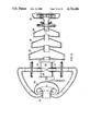
- FIG. 1 is a side elevation showing the swirl chamber.
- FIG. 2 is a sectional view taken on line A-B in FIG. 1.
- FIG. 3 is a top plan view showing that end of the swirl chamber of FIG. 1 where the discharge tube is provided.
- FIG. 4 is a top plan view showing that end of the swirl chamber of FIG. 1 where the inlet nozzle is provided.
- FIG. 5 is a longitudinal sectional view showing a centrifuging chamber which succeeds the swirl chamber of FIG. 1.
- FIG. 6 is a transverse sectional view showing the centrifuging chamber of FIG. 5.
- FIG. 7 is a longitudinal sectional view which is similar to FIG. 1 but drawn to a larger scale.
- FIG. 8 is a longitudinal sectional view showing a carburetor for an internal combustion engine, which carburetor comprises a swirl chamber and a succeeding centrifuging chamber.
- FIG. 9 is a longitudinal sectional view showing a twin vortex carburetor.
- FIG. 10 is a longitudinal sectional view showing an oil burner.
- FIG. 11 is a transverse sectional view showing a system for humidifying and purifying air and for collecting dust.
- FIG. 12 is a diagrammatic longitudinal sectional view showing a clarifier.
- FIG. 13 is a diagrammatic longitudinal sectional view showing a refining plant.
- FIG. 14 is a diagrammatic longitudinal sectional view showing a flue gas detoxicating system.
- the swirl chamber 1 shown in FIGS. 1 to 4 comprises a cylindrical tubular body 2, which is closed at opposite ends by end plates 3, 4 joined to the tubular body 2.
- the tubular member 2 constitutes the shell of the housing of the swirl chamber 1.
- Two tubular ports 5, 6 are joined to the tubular body 2 in its transverse center plane at locations which are spaced 180° apart. As is apparent from FIG. 2, the tubular ports 5, 6 open tangentially into the swirl chamber. Because the tubular ports 5, 6 are spaced 180° apart, their center lines 7, 8 are parallel to each other. As is apparent from FIG. 1 the center lines 7, 8 of the tubular ports 5, 6 intersect the center line 10 of the swirl chamber 1 at right angles thereto.
- the end plate 3 of the swirl chamber 1 is provided with the discharge tube 12.
- the inlet nozzle 13 is mounted in the opposite end plate 4.
- the center lines of the discharge tube 12 and of the inlet nozzle 13 are aligned with the center line of the housing of the swirl chamber.
- That chamber comprises a housing 15, which is rotationally symmetrical and approximately pear-shaped.
- the housing 15 is provided at one end with an entrance tube 16 and at the other end with an exit tube 17.
- the entrance and exit tubes 16 and 17 are concentric and centered on the center line of the centrifuging chamber 15 and are tightly fitted in mating openings formed in the ends of said chamber.
- the entrance tube 16 is constituted by the discharge tube of the swirl chamber 1.
- the inner ends 18, 19 of the entrance tube 16 and the exit tube 17, respectively, are spaced a predetermined distance a apart. That cross-section 20 of the centrifuging chamber 15 which is largest in diameter is disposed in a plane extending between the inner ends 18, 19 of the tubes 16, 17. In that portion which is largest in diameter, the centrifuging chamber 15 has a curved contour in longitudinal section. The centrifuging chamber 15 decreases in diameter from that portion toward the entrance tube 16 and toward the exit tube 17 and has a smaller diameter at the entrance tube 16 than at the exit tube 17.
- the centrifuging chamber 15 Adjacent to that cross-section which is largest in diameter, the centrifuging chamber 15 is provided with an approximately tangentially extending extracting pipe 20, which may incorporated a valve or construction 21.
- a swirling jet 25 entering the centrifuging chamber 15 through the entrance tube 16 can widen between the inner ends 18, 19 of the tubes 16, 17 to form a vortex 26, which is larger in diameter. Particles 27 disposed in the vortex near its circumference will be centrifugally separated and can be withdrawn through the extracting pipe 20.
- FIGS. 1 to 7 Some applications of the apparatus shown in FIGS. 1 to 7 will now be explained by way of example with reference to FIGS. 8 to 14.
- FIG. 8 shows a single swirling carburetor comprising the swirl chamber 1 and the centrifuging chamber 15 connected to the swirl chamber 1.
- An internal combustion engine sucks a fuel-air mixture through a pipe 30 so that a vacuum is produced in the swirl chamber 1 and causes air to flow through the tubular ports 6, 7, into the swirl chamber 1, in which said air forms a convergent vortex.
- Fuel is supplied by a fuel feeder 31 through the nozzle 13 into the swirling convergent air jet and is atomized to form very small particles in the swirling air jet.
- the swirling fuel-air jet then flows through the entrance tube 16 into the centrifuging chamber 15, in which relatively large liquid droplets are centrifugally separated and are collected in that portion 32 in which the centrifuging chamber 15 is largest in diameter and from which said droplets are discharged through the extraction pipe 33.
- the fuel which has thus been extracted is then recycled by lines which are not shown and is fed once more through the nozzle 13.
- the exit tube 17 contains a throttle valve 34 for infinitely adjusting the flow area at the exit end of the exit tube 34.
- the throttle valve comprises two gates 35, 36, which are formed with overlapping V-shaped identations, which define a square opening, and the gates can be displaced relatively to each other to vary the area of said opening.
- the throttle valve may alternatively be constituted by an iris diaphragm.
- FIG. 9 shows a twin swirling carburetor, in which two swirling carburetors of the kind described with reference to FIG. 8 are connected to a succeeding additional swirl chamber 40, from which the fuel-air mixture forming a swirling jet is sucked through the suction tube 41.
- FIG. 10 shows the concept of an oil burner comprising two radial fans 50, 51, which blow air into the swirl chamber 1 through the tubular ports 5, 6. Fuel is injected through the nozzle 13 and is atomized in the vortex of air and the resulting fuel-air jet enters the centrifuging chamber 15 through the tube 16. Centrifugally separated fuel droplets are extracted through extracting pipe 53 and are recycled. The swirling fuel-air jet is supplied to the burner through a pipe 54.
- FIG. 11 is a diagrammatic view showing a system for humidifying and purifying air and for collecting dust.
- Air to be conditioned enters the swirl chamber through the tubular intake ports, only one of which, designated 5, is apparent in the sectional view.
- Water is supplied through nozzle 13 to the air which is to be purified and humidified.
- the water is atomized in the swirling air jet to form very fine particles and the resulting water-air aerosol enters the centrifuging chamber 15, in which dust particles that have been agglomerated by the injected water are centrifugally separated and subsequently extracted through the extracting duct 60.
- the air which has been humidified and purified is sucked and discharged by the fan 61.
- FIG. 12 is a diagrammatic view showing a clarifier or a system for recovering water of high purity.
- the water to be purified enters the swirl chamber 72 through the tubular ports 70, 71.
- Heavy particles to be removed are centrifugally separated in the succeeding centrifuging chambers 73 to 76 and are extracted through the extracting lines 77 to 80.
- the water to be purified is sucked by a centrifugal pump 81.
- the swirling jet produced in the swirl chamber 72 is still present in the exit tube of the last centrifuging chamber 76 in the direction of flow. Because the diameters of the exit tubes of the centrifuging chambers progressively decrease in the direction of flow, the substances to be removed are selectively removed in respective centrifuging chambers.
- FIG. 13 is a diagrammatic view showing a refining system.
- the liquid to be purified is sucked by the centrifugal pump 90 and enters the swirl chamber 93 through the tubular ports 91, 92.
- the substances to be removed are selectively separated in the centrifuging chambers 94 to 98.
- FIG. 14 is a diagrammatic view showing a swirling absorber for detoxicating flue gases.
- the flue gas to be purified is sucked by the fan 100 and through the intake tube 101 enters a cyclone chamber 102, in which coarse dust particles are centrifugally separated.
- the flue gas is then sucked through the tubular ports 103, 104 and through adjustable throttle valves enters the swirl chamber 105.
- a liquid preferably consisting of water is injected through the nozzle 106 and causes dust to agglomerate and absorbs gases which are to be removed.
- Those constituents of the flue gas what are to be removed are selectively separated in the succeeding centrifuging chambers 107 to 109 so that a purified detoxicated flue gas is discharged by the fan 100.
Abstract
Description
Claims (18)
Applications Claiming Priority (4)
| Application Number | Priority Date | Filing Date | Title |
|---|---|---|---|
| DE8521904[U] | 1985-07-30 | ||
| DE19858521904 DE8521904U1 (en) | 1985-07-30 | 1985-07-30 | Centrifugal chamber, for ejecting non-atomized liquid particles from centric eddies |
| DE8521902U DE8521902U1 (en) | 1985-07-30 | 1985-07-30 | Vortex atomization chamber, which generates stable, self-centering vortices, for the purpose of molecularly fine atomization of liquid (or powdery solid) with air (or gas) |
| DE8521902[U] | 1985-07-30 |
Publications (1)
| Publication Number | Publication Date |
|---|---|
| US4726686A true US4726686A (en) | 1988-02-23 |
Family
ID=25950398
Family Applications (1)
| Application Number | Title | Priority Date | Filing Date |
|---|---|---|---|
| US06/888,807 Expired - Lifetime US4726686A (en) | 1985-07-30 | 1986-07-24 | Swirl chamber |
Country Status (5)
| Country | Link |
|---|---|
| US (1) | US4726686A (en) |
| EP (1) | EP0213329B1 (en) |
| JP (1) | JPH0687930B2 (en) |
| AT (1) | ATE67939T1 (en) |
| DE (1) | DE3681768D1 (en) |
Cited By (81)
| Publication number | Priority date | Publication date | Assignee | Title |
|---|---|---|---|---|
| US4834343A (en) * | 1985-07-13 | 1989-05-30 | Boyes Adrian P | Gas liquid contacting method |
| US5059357A (en) * | 1989-06-05 | 1991-10-22 | Hartmut Wolf | Vortex chamber atomizer |
| US5112498A (en) * | 1989-11-28 | 1992-05-12 | Orkney Water Test Centre Limited | Method of coalescing a disperse phase within a continous phrase of a fluid mixture |
| US5124034A (en) * | 1991-02-28 | 1992-06-23 | Infilco Degremont Inc. | Liquid purification systems |
| US5124049A (en) * | 1991-02-28 | 1992-06-23 | Infilco Degremont Inc. | Liquid purification methods |
| WO1993000157A1 (en) * | 1991-06-26 | 1993-01-07 | Irvine Scientific Sales Co. | Mixing apparatus |
| US5224604A (en) * | 1990-04-11 | 1993-07-06 | Hydro Processing & Mining Ltd. | Apparatus and method for separation of wet and dry particles |
| US5322646A (en) * | 1993-08-03 | 1994-06-21 | Amazing Things | Simulated tornado humidifier |
| WO1994022566A1 (en) * | 1993-04-02 | 1994-10-13 | Irvine Scientific Sales Co. | Dissolution apparatus |
| US5435913A (en) * | 1994-04-14 | 1995-07-25 | Ashbrook; Clifford L. | Fluid treating apparatus |
| US5523063A (en) * | 1992-12-02 | 1996-06-04 | Applied Materials, Inc. | Apparatus for the turbulent mixing of gases |
| US5624609A (en) * | 1994-11-28 | 1997-04-29 | E & M Lamort | Enhancements to the air injection devices in a paper pulp flow for de-inking thereof |
| US5653813A (en) * | 1995-04-03 | 1997-08-05 | Novellus Systems, Inc. | Cyclone evaporator |
| US5753110A (en) * | 1995-05-31 | 1998-05-19 | Biomaterial Co., Ltd. | Biochemical reactor of liquid current type, groundwater and wastewater purifying system equipped therewith, and liquid transport-stirring apparatus that employs the transport means used in said reactor and system |
| US5858237A (en) * | 1997-04-29 | 1999-01-12 | Natural Resources Canada | Hydrocyclone for separating immiscible fluids and removing suspended solids |
| WO1999047806A3 (en) * | 1998-03-18 | 1999-12-02 | Lytesyde L L C | Fluid processing system and method |
| US6004517A (en) * | 1995-05-24 | 1999-12-21 | The Dow Chemical Company | Process to make allyl chloride and reactor useful in that process |
| US6106145A (en) * | 1999-03-31 | 2000-08-22 | Baker Hughes Incorporated | Adjustable homogenizer device |
| EP1112773A1 (en) * | 1999-05-15 | 2001-07-04 | Hirofumi Ohnari | Swing type fine air bubble generating device |
| US6283626B1 (en) * | 1998-10-02 | 2001-09-04 | Institute For Advanced Engineering | Multiphase mixing apparatus using acoustic resonance |
| US20020131325A1 (en) * | 1998-02-26 | 2002-09-19 | Jouni Matula | Method and apparatus for feeding a chemical into a liquid flow |
| WO2002098538A1 (en) * | 2001-06-01 | 2002-12-12 | Celanese International Corporation | Methods for reducing entrainment of solids and liquids |
| US6659636B1 (en) * | 1998-02-26 | 2003-12-09 | Wetend Technologies Oy | Method and apparatus for feeding a chemical into a liquid flow |
| US20050035219A1 (en) * | 2003-08-15 | 2005-02-17 | Rock Kelly P. | Fuel processor apparatus and method |
| US20050189293A1 (en) * | 2005-05-04 | 2005-09-01 | Bernard Robert H. | Method and apparatus for separating fluids having different densities |
| US20050271992A1 (en) * | 2004-06-02 | 2005-12-08 | Degrazia Torey W Jr | Air:fluid distribution system and method |
| US20060107998A1 (en) * | 2004-11-05 | 2006-05-25 | Kholy Ismail E | Dry polymer hydration apparatus and methods of use |
| US20060217618A1 (en) * | 2000-09-25 | 2006-09-28 | Welch Allyn, Inc. | Blood pressure measuring apparatus |
| US20060293600A1 (en) * | 2000-09-25 | 2006-12-28 | Welch Allyn, Inc. | Blood pressure measuring apparatus |
| US20070169773A1 (en) * | 2006-01-23 | 2007-07-26 | Lytesyde, Llc | Medical liquid processor apparatus and method |
| US20070169760A1 (en) * | 2006-01-23 | 2007-07-26 | Rock Kelly P | Fuel processor apparatus and method |
| US20080048348A1 (en) * | 2006-07-11 | 2008-02-28 | Shung-Chi Kung | Circulation water vortex bubble generation device for aquaculture pond |
| US20080061008A1 (en) * | 2006-09-12 | 2008-03-13 | Kelsey Robert L | Systems and methods for treating metalworking fluids |
| US20080093392A1 (en) * | 2004-12-01 | 2008-04-24 | Incro Limited | Nozzle Arrangement Comprising a Swirl Chamber |
| US20080127954A1 (en) * | 2006-11-30 | 2008-06-05 | Coates George J | In line mixing chamber for internal combustion engine |
| US20080160604A1 (en) * | 2006-12-29 | 2008-07-03 | Amit Gupta | Apparatus for producing a stable oxidizing biocide |
| US20080198690A1 (en) * | 2005-03-14 | 2008-08-21 | Hartmut Wolf | Mixing Device |
| US20080232907A1 (en) * | 2004-06-18 | 2008-09-25 | Clyde Materials Handling Limited | Pneumatic Conveying Device for Bulk Material |
| US20080257411A1 (en) * | 2007-04-18 | 2008-10-23 | Kelsey Robert L | Systems and methods for preparation of emulsions |
| US20080257974A1 (en) * | 2007-04-18 | 2008-10-23 | Kelsey Robert L | Systems and methods for degassing one or more fluids |
| US20080257828A1 (en) * | 2007-04-18 | 2008-10-23 | Kelsey Robert L | Systems and methods for reduction of metal contaminants in fluids |
| US20090038582A1 (en) * | 2007-08-07 | 2009-02-12 | Lytesyde, Llc | Fuel Processor Apparatus and Method |
| US20090152212A1 (en) * | 2007-04-18 | 2009-06-18 | Kelsey Robert L | Systems and methods for treatment of groundwater |
| US7651614B2 (en) | 2007-02-13 | 2010-01-26 | Vrtx Technologies, Llc | Methods for treatment of wastewater |
| US20100067323A1 (en) * | 2006-11-06 | 2010-03-18 | Micronit Microfluidics B.V. | Micromixing Chamber, Micromixer Comprising a Plurality of Such Micromixing Chambers, Methods for Manufacturing Thereof, and Methods for Mixing |
| US20100298724A1 (en) * | 2009-05-19 | 2010-11-25 | Welch Allyn, Inc. | Recyclable or biodegradable blood pressure cuff |
| US20100298725A1 (en) * | 2009-05-19 | 2010-11-25 | Vivenzio Robert L | Recyclable or biodegradable blood pressure cuff |
| US20110087055A1 (en) * | 2009-10-09 | 2011-04-14 | Dow Global Technologies | Processes for the production of chlorinated and/or fluorinated propenes and higher alkenes |
| US20110087054A1 (en) * | 2009-10-09 | 2011-04-14 | Dow Global Technologies | Isothermal multitube reactors and processes incorporating the same |
| US20110087056A1 (en) * | 2009-10-09 | 2011-04-14 | Dow Global Technologies | Adiabatic plug flow reactors and processes incorporating the same |
| US20110083955A1 (en) * | 2009-10-09 | 2011-04-14 | Dow Global Technologies, Inc | Process for the production of chlorinated and/or fluorinated propenes |
| US20110178343A1 (en) * | 2008-10-13 | 2011-07-21 | Dow Global Technologies, Inc. | Process for the production of chlorinated and/or fluorinated propenes |
| USD643536S1 (en) | 2009-05-19 | 2011-08-16 | Welch Allyn, Inc. | Blood-pressure cuff |
| GB2480232A (en) * | 2010-05-05 | 2011-11-16 | Arumugam Gunasegaran | Gas energiser device eg for the intake of an i.c. engine |
| US20120069698A1 (en) * | 2010-09-17 | 2012-03-22 | Delavan Inc | Mixers for immiscible fluids |
| US20140144319A1 (en) * | 2012-11-27 | 2014-05-29 | John J. Paoluccio | Orbit filter magnets for cyclonic cleaners |
| US8907148B2 (en) | 2011-08-07 | 2014-12-09 | Dow Global Technologies Llc | Process for the production of chlorinated propenes |
| US8907149B2 (en) | 2011-05-31 | 2014-12-09 | Dow Global Technologies Llc | Process for the production of chlorinated propenes |
| US8927792B2 (en) | 2011-06-08 | 2015-01-06 | Dow Agrosciences, Llc | Process for the production of chlorinated and/or fluorinated propenes |
| US8955325B1 (en) * | 2011-08-31 | 2015-02-17 | The United States Of America, As Represented By The Secretary Of The Navy | Charged atomization of fuel for increased combustion efficiency in jet engines |
| US9056808B2 (en) | 2011-05-31 | 2015-06-16 | Dow Global Technologies, Llc | Process for the production of chlorinated propenes |
| US9067855B2 (en) | 2011-11-21 | 2015-06-30 | Dow Global Technologies Llc | Process for the production of chlorinated alkanes |
| US9169177B2 (en) | 2011-12-22 | 2015-10-27 | Blue Cube Ip Llc | Process for the production of tetrachloromethane |
| US9199899B2 (en) | 2011-12-02 | 2015-12-01 | Blue Cube Ip Llc | Process for the production of chlorinated alkanes |
| US9220422B2 (en) | 2012-11-19 | 2015-12-29 | Welch Allyn, Inc. | Blood pressure sleeve |
| US9233896B2 (en) | 2011-08-07 | 2016-01-12 | Blue Cube Ip Llc | Process for the production of chlorinated propenes |
| US9284239B2 (en) | 2011-12-02 | 2016-03-15 | Blue Cube Ip Llc | Process for the production of chlorinated alkanes |
| US9321707B2 (en) | 2012-09-20 | 2016-04-26 | Blue Cube Ip Llc | Process for the production of chlorinated propenes |
| US9334205B2 (en) | 2011-12-13 | 2016-05-10 | Blue Cube Ip Llc | Process for the production of chlorinated propanes and propenes |
| US9382176B2 (en) | 2013-02-27 | 2016-07-05 | Blue Cube Ip Llc | Process for the production of chlorinated propenes |
| US9403741B2 (en) | 2013-03-09 | 2016-08-02 | Blue Cube Ip Llc | Process for the production of chlorinated alkanes |
| US9475740B2 (en) | 2012-12-19 | 2016-10-25 | Blue Cube Ip Llc | Process for the production of chlorinated propenes |
| US9512053B2 (en) | 2012-12-18 | 2016-12-06 | Blue Cube Ip Llc | Process for the production of chlorinated propenes |
| US9512049B2 (en) | 2011-12-23 | 2016-12-06 | Dow Global Technologies Llc | Process for the production of alkenes and/or aromatic compounds |
| US9598334B2 (en) | 2012-09-20 | 2017-03-21 | Blue Cube Ip Llc | Process for the production of chlorinated propenes |
| US9795941B2 (en) | 2012-09-30 | 2017-10-24 | Blue Cube Ip Llc | Weir quench and processes incorporating the same |
| US10065157B2 (en) | 2012-10-26 | 2018-09-04 | Blue Cube Ip Llc | Mixer and processes incorporating the same |
| US10413199B2 (en) | 2017-11-02 | 2019-09-17 | Welch Allyn, Inc. | Connectors for medical equipment |
| US11059002B2 (en) * | 2016-11-02 | 2021-07-13 | Bkt Co., Ltd. | Pivoting gas/liquid dissolution device |
| US11293096B2 (en) * | 2015-07-16 | 2022-04-05 | Kokusai Electric Corporation | Substrate processing apparatus, method for manufacturing semiconductor device and vaporizer |
| US11674223B2 (en) * | 2019-04-24 | 2023-06-13 | Applied Materials, Inc. | Reactor for coating particles in stationary chamber with rotating paddles and gas injection |
Families Citing this family (6)
| Publication number | Priority date | Publication date | Assignee | Title |
|---|---|---|---|---|
| NL8700996A (en) * | 1987-04-28 | 1988-11-16 | Ir Paul Martin Hofmeester | APPARATUS FOR MIXING GAS OR GASES WITH AIR IN AN ADJUSTABLE MIXING FOR A COMBUSTION MACHINE. |
| WO1995016521A1 (en) * | 1993-12-13 | 1995-06-22 | Rubenberger, Karl | Atomizer |
| JPH09122536A (en) * | 1995-10-30 | 1997-05-13 | Mitsubishi Heavy Ind Ltd | Device for separating liquid particle in gas |
| DE19712242A1 (en) * | 1997-03-03 | 1998-09-17 | Jean Denis Rochat | Particle separation apparatus for use in separating e.g. biological fluids |
| CA2715733A1 (en) * | 2009-11-24 | 2011-05-24 | Sulzer Chemtech Ag | Fluid inlet apparatus |
| DE102019002244A1 (en) | 2019-03-29 | 2020-10-01 | Grohe Ag | Method and device for reducing residual pressure in a fluid line |
Citations (2)
| Publication number | Priority date | Publication date | Assignee | Title |
|---|---|---|---|---|
| US2653801A (en) * | 1950-10-13 | 1953-09-29 | Stamicarbon | Process and apparatus for dispersing a substance in a liquid |
| US4244708A (en) * | 1976-03-10 | 1981-01-13 | Messerschmitt-Boelkow-Blohm Gesellschaft Mit Beschrankter Haftung | Method and apparatus for separating components from a flowing medium by means of centrifugal force |
Family Cites Families (12)
| Publication number | Priority date | Publication date | Assignee | Title |
|---|---|---|---|---|
| US1525249A (en) * | 1921-03-30 | 1925-02-03 | Swartwout Co | Separator |
| US1931193A (en) * | 1932-03-08 | 1933-10-17 | Centriflx Corp | Centrifugal separator |
| GB577966A (en) * | 1945-01-17 | 1946-06-06 | Tom Conrad Bieth | Improvements in apparatus for removing dust from flue gases |
| US2487633A (en) * | 1947-01-29 | 1949-11-08 | Jr Joseph Breslove | Separator |
| DE973021C (en) * | 1950-09-07 | 1959-11-19 | Waagner Biro Ag | Centrifugal dust separator with a multi-stage centrifugal chamber that runs straight through from the rotational flow in the axial direction |
| NL171445C (en) * | 1952-07-28 | Chinoin Gyogyszer Es Vegyeszet | PROCESS FOR PREPARING 3-AMINO-DELTAŸ2-PYRAZOLINE DERIVATIVES. | |
| DE2220534C3 (en) * | 1972-04-26 | 1975-04-30 | Siemens Ag, 1000 Berlin Und 8000 Muenchen | Rotary flow vortex for the sifting and separation of fine-grained particles |
| DE2220535C2 (en) * | 1972-04-26 | 1974-03-07 | Siemens Ag, 1000 Berlin U. 8000 Muenchen | Rotary flow vortex for the sifting of fine-grained particles |
| US4053142A (en) * | 1976-06-11 | 1977-10-11 | Eastman Kodak Company | Nonmechanical shearing mixer |
| DE2741243A1 (en) * | 1977-09-14 | 1979-03-22 | Werner Anliker | Ejector mixer for fluids partic. gas into liq. - to aerate waste water and treat liq. manure |
| US4464314A (en) * | 1980-01-02 | 1984-08-07 | Surovikin Vitaly F | Aerodynamic apparatus for mixing components of a fuel mixture |
| DE3039510A1 (en) * | 1980-10-20 | 1982-06-03 | Hoechst Ag, 6000 Frankfurt | DEVICE AND METHOD FOR DISPERSING AND SOLVING POLYMER POWDERS |
-
1986
- 1986-07-08 AT AT86109340T patent/ATE67939T1/en not_active IP Right Cessation
- 1986-07-08 EP EP86109340A patent/EP0213329B1/en not_active Expired - Lifetime
- 1986-07-08 DE DE8686109340T patent/DE3681768D1/en not_active Expired - Fee Related
- 1986-07-24 US US06/888,807 patent/US4726686A/en not_active Expired - Lifetime
- 1986-07-30 JP JP61179794A patent/JPH0687930B2/en not_active Expired - Lifetime
Patent Citations (2)
| Publication number | Priority date | Publication date | Assignee | Title |
|---|---|---|---|---|
| US2653801A (en) * | 1950-10-13 | 1953-09-29 | Stamicarbon | Process and apparatus for dispersing a substance in a liquid |
| US4244708A (en) * | 1976-03-10 | 1981-01-13 | Messerschmitt-Boelkow-Blohm Gesellschaft Mit Beschrankter Haftung | Method and apparatus for separating components from a flowing medium by means of centrifugal force |
Cited By (129)
| Publication number | Priority date | Publication date | Assignee | Title |
|---|---|---|---|---|
| US4834343A (en) * | 1985-07-13 | 1989-05-30 | Boyes Adrian P | Gas liquid contacting method |
| US5059357A (en) * | 1989-06-05 | 1991-10-22 | Hartmut Wolf | Vortex chamber atomizer |
| US5112498A (en) * | 1989-11-28 | 1992-05-12 | Orkney Water Test Centre Limited | Method of coalescing a disperse phase within a continous phrase of a fluid mixture |
| US5224604A (en) * | 1990-04-11 | 1993-07-06 | Hydro Processing & Mining Ltd. | Apparatus and method for separation of wet and dry particles |
| US5124034A (en) * | 1991-02-28 | 1992-06-23 | Infilco Degremont Inc. | Liquid purification systems |
| US5124049A (en) * | 1991-02-28 | 1992-06-23 | Infilco Degremont Inc. | Liquid purification methods |
| US5470151A (en) * | 1991-06-26 | 1995-11-28 | Irvine Scientific Sales Co. | Mixing apparatus |
| WO1993000157A1 (en) * | 1991-06-26 | 1993-01-07 | Irvine Scientific Sales Co. | Mixing apparatus |
| US5326165A (en) * | 1991-06-26 | 1994-07-05 | Irvine Scientific Sales Co. | Mixing apparatus |
| US5523063A (en) * | 1992-12-02 | 1996-06-04 | Applied Materials, Inc. | Apparatus for the turbulent mixing of gases |
| US5573334A (en) * | 1992-12-02 | 1996-11-12 | Applied Materials, Inc. | Method for the turbulent mixing of gases |
| WO1994022566A1 (en) * | 1993-04-02 | 1994-10-13 | Irvine Scientific Sales Co. | Dissolution apparatus |
| US5322646A (en) * | 1993-08-03 | 1994-06-21 | Amazing Things | Simulated tornado humidifier |
| US5435913A (en) * | 1994-04-14 | 1995-07-25 | Ashbrook; Clifford L. | Fluid treating apparatus |
| US5624609A (en) * | 1994-11-28 | 1997-04-29 | E & M Lamort | Enhancements to the air injection devices in a paper pulp flow for de-inking thereof |
| US5901271A (en) * | 1995-04-03 | 1999-05-04 | Novellus Systems, Inc. | Process of evaporating a liquid in a cyclone evaporator |
| US5653813A (en) * | 1995-04-03 | 1997-08-05 | Novellus Systems, Inc. | Cyclone evaporator |
| US6004517A (en) * | 1995-05-24 | 1999-12-21 | The Dow Chemical Company | Process to make allyl chloride and reactor useful in that process |
| US5753110A (en) * | 1995-05-31 | 1998-05-19 | Biomaterial Co., Ltd. | Biochemical reactor of liquid current type, groundwater and wastewater purifying system equipped therewith, and liquid transport-stirring apparatus that employs the transport means used in said reactor and system |
| US5858237A (en) * | 1997-04-29 | 1999-01-12 | Natural Resources Canada | Hydrocyclone for separating immiscible fluids and removing suspended solids |
| US7758725B2 (en) | 1998-02-26 | 2010-07-20 | Wetend Technologies Oy | Method of mixing a paper making chemical into a fiber suspension flow |
| US20070258316A1 (en) * | 1998-02-26 | 2007-11-08 | Wetend Technologies Oy | Method of mixing a paper making chemical into a fiber suspension flow |
| US7234857B2 (en) * | 1998-02-26 | 2007-06-26 | Wetend Technologies Oy | Method and apparatus for feeding a chemical into a liquid flow |
| US6659636B1 (en) * | 1998-02-26 | 2003-12-09 | Wetend Technologies Oy | Method and apparatus for feeding a chemical into a liquid flow |
| US20020131325A1 (en) * | 1998-02-26 | 2002-09-19 | Jouni Matula | Method and apparatus for feeding a chemical into a liquid flow |
| US6648306B2 (en) | 1998-03-18 | 2003-11-18 | Lytesyde, Llc | Fluid processing system and method |
| US6347789B1 (en) | 1998-03-18 | 2002-02-19 | Lytesyde, L.L.C. | Fluid processing system |
| US6113078A (en) * | 1998-03-18 | 2000-09-05 | Lytesyde, Llc | Fluid processing method |
| US6244573B1 (en) | 1998-03-18 | 2001-06-12 | Lytesyde, Llc | Fluid processing system |
| WO1999047806A3 (en) * | 1998-03-18 | 1999-12-02 | Lytesyde L L C | Fluid processing system and method |
| US6283626B1 (en) * | 1998-10-02 | 2001-09-04 | Institute For Advanced Engineering | Multiphase mixing apparatus using acoustic resonance |
| US6106145A (en) * | 1999-03-31 | 2000-08-22 | Baker Hughes Incorporated | Adjustable homogenizer device |
| US7472893B2 (en) | 1999-05-15 | 2009-01-06 | Hirofumi Ohnari | Swirling type micro-bubble generating system |
| US7261283B1 (en) * | 1999-05-15 | 2007-08-28 | Hirofumi Ohnari | Swing type fine air bubble generating device |
| US20070267763A1 (en) * | 1999-05-15 | 2007-11-22 | Hirofumi Ohnari | Swirling type micro-bubble generating system |
| EP1112773A4 (en) * | 1999-05-15 | 2004-08-25 | Hirofumi Ohnari | Swing type fine air bubble generating device |
| EP1112773A1 (en) * | 1999-05-15 | 2001-07-04 | Hirofumi Ohnari | Swing type fine air bubble generating device |
| US20060217618A1 (en) * | 2000-09-25 | 2006-09-28 | Welch Allyn, Inc. | Blood pressure measuring apparatus |
| US20060293600A1 (en) * | 2000-09-25 | 2006-12-28 | Welch Allyn, Inc. | Blood pressure measuring apparatus |
| US9072435B2 (en) | 2000-09-25 | 2015-07-07 | Welch Allyn, Inc. | Blood pressure measuring apparatus |
| US7780603B2 (en) | 2000-09-25 | 2010-08-24 | Welch Allyn, Inc. | Blood pressure measuring apparatus |
| US8535233B2 (en) | 2000-09-25 | 2013-09-17 | Welch Allyn, Inc. | Blood pressure measuring apparatus |
| CZ301242B6 (en) * | 2001-06-01 | 2009-12-16 | Celanese International Corporation | Method for reducing entrainment of solids and liquids in vapor flow exiting separation vessel |
| WO2002098538A1 (en) * | 2001-06-01 | 2002-12-12 | Celanese International Corporation | Methods for reducing entrainment of solids and liquids |
| US7104528B2 (en) | 2003-08-15 | 2006-09-12 | Lytesyde, Llc | Fuel processor apparatus and method |
| US20050035219A1 (en) * | 2003-08-15 | 2005-02-17 | Rock Kelly P. | Fuel processor apparatus and method |
| US20050271992A1 (en) * | 2004-06-02 | 2005-12-08 | Degrazia Torey W Jr | Air:fluid distribution system and method |
| US20100269934A1 (en) * | 2004-06-02 | 2010-10-28 | Fuel Management, Inc. | Air:fluid distribution system and method |
| US8162237B2 (en) | 2004-06-02 | 2012-04-24 | Fuel Management, Inc. | Air:fluid distribution system and method |
| US7695275B2 (en) * | 2004-06-02 | 2010-04-13 | Fuel Management, Inc. | Air:fluid distribution system and method |
| US20080232907A1 (en) * | 2004-06-18 | 2008-09-25 | Clyde Materials Handling Limited | Pneumatic Conveying Device for Bulk Material |
| US20060107998A1 (en) * | 2004-11-05 | 2006-05-25 | Kholy Ismail E | Dry polymer hydration apparatus and methods of use |
| US7866881B2 (en) | 2004-11-05 | 2011-01-11 | Schlumberger Technology Corporation | Dry polymer hydration apparatus and methods of use |
| US20100246318A1 (en) * | 2004-11-05 | 2010-09-30 | Ismail El Kholy | Dry Polymer Hydration Apparatus and methods of Use |
| US7794135B2 (en) * | 2004-11-05 | 2010-09-14 | Schlumberger Technology Corporation | Dry polymer hydration apparatus and methods of use |
| US20080093392A1 (en) * | 2004-12-01 | 2008-04-24 | Incro Limited | Nozzle Arrangement Comprising a Swirl Chamber |
| US20080198690A1 (en) * | 2005-03-14 | 2008-08-21 | Hartmut Wolf | Mixing Device |
| US8573830B2 (en) * | 2005-03-14 | 2013-11-05 | Hartmut Wolf | Mixing device |
| US7479231B2 (en) | 2005-05-04 | 2009-01-20 | Bernard Robert H | Method and apparatus for separating fluids having different densities |
| US20050189293A1 (en) * | 2005-05-04 | 2005-09-01 | Bernard Robert H. | Method and apparatus for separating fluids having different densities |
| US7681569B2 (en) | 2006-01-23 | 2010-03-23 | Lytesyde, Llc | Medical liquid processor apparatus and method |
| US20070169773A1 (en) * | 2006-01-23 | 2007-07-26 | Lytesyde, Llc | Medical liquid processor apparatus and method |
| US7717096B2 (en) | 2006-01-23 | 2010-05-18 | Lytesyde, Llc | Fuel processor apparatus and method |
| US20070169760A1 (en) * | 2006-01-23 | 2007-07-26 | Rock Kelly P | Fuel processor apparatus and method |
| US20080048348A1 (en) * | 2006-07-11 | 2008-02-28 | Shung-Chi Kung | Circulation water vortex bubble generation device for aquaculture pond |
| US20080061008A1 (en) * | 2006-09-12 | 2008-03-13 | Kelsey Robert L | Systems and methods for treating metalworking fluids |
| US20100067323A1 (en) * | 2006-11-06 | 2010-03-18 | Micronit Microfluidics B.V. | Micromixing Chamber, Micromixer Comprising a Plurality of Such Micromixing Chambers, Methods for Manufacturing Thereof, and Methods for Mixing |
| US8740448B2 (en) * | 2006-11-06 | 2014-06-03 | Marko Theodoor Blom | Micromixing chamber, micromixer comprising a plurality of such micromixing chambers, methods for manufacturing thereof, and methods for mixing |
| US20080127954A1 (en) * | 2006-11-30 | 2008-06-05 | Coates George J | In line mixing chamber for internal combustion engine |
| US20080160604A1 (en) * | 2006-12-29 | 2008-07-03 | Amit Gupta | Apparatus for producing a stable oxidizing biocide |
| US7651614B2 (en) | 2007-02-13 | 2010-01-26 | Vrtx Technologies, Llc | Methods for treatment of wastewater |
| US20080257411A1 (en) * | 2007-04-18 | 2008-10-23 | Kelsey Robert L | Systems and methods for preparation of emulsions |
| US20080257974A1 (en) * | 2007-04-18 | 2008-10-23 | Kelsey Robert L | Systems and methods for degassing one or more fluids |
| US7651621B2 (en) | 2007-04-18 | 2010-01-26 | Vrtx Technologies, Llc | Methods for degassing one or more fluids |
| US20080257828A1 (en) * | 2007-04-18 | 2008-10-23 | Kelsey Robert L | Systems and methods for reduction of metal contaminants in fluids |
| US20090152212A1 (en) * | 2007-04-18 | 2009-06-18 | Kelsey Robert L | Systems and methods for treatment of groundwater |
| US8028674B2 (en) | 2007-08-07 | 2011-10-04 | Lytesyde, Llc | Fuel processor apparatus and method |
| US20090038582A1 (en) * | 2007-08-07 | 2009-02-12 | Lytesyde, Llc | Fuel Processor Apparatus and Method |
| US8258353B2 (en) | 2008-10-13 | 2012-09-04 | Dow Global Technologies, Llc | Process for the production of chlorinated and/or fluorinated propenes |
| US20110178343A1 (en) * | 2008-10-13 | 2011-07-21 | Dow Global Technologies, Inc. | Process for the production of chlorinated and/or fluorinated propenes |
| US8652057B2 (en) | 2009-05-19 | 2014-02-18 | Welch Allyn, Inc. | Recyclable or biodegradable blood pressure cuff |
| US11350834B2 (en) | 2009-05-19 | 2022-06-07 | Welch Allyn, Inc. | Recyclable or biodegradable blood pressure cuff |
| US20100298724A1 (en) * | 2009-05-19 | 2010-11-25 | Welch Allyn, Inc. | Recyclable or biodegradable blood pressure cuff |
| US20100298725A1 (en) * | 2009-05-19 | 2010-11-25 | Vivenzio Robert L | Recyclable or biodegradable blood pressure cuff |
| USD643536S1 (en) | 2009-05-19 | 2011-08-16 | Welch Allyn, Inc. | Blood-pressure cuff |
| US10231630B2 (en) | 2009-05-19 | 2019-03-19 | Welch Allyn, Inc. | Recyclable or biodegradable blood pressure cuff |
| US20110087056A1 (en) * | 2009-10-09 | 2011-04-14 | Dow Global Technologies | Adiabatic plug flow reactors and processes incorporating the same |
| US20110087055A1 (en) * | 2009-10-09 | 2011-04-14 | Dow Global Technologies | Processes for the production of chlorinated and/or fluorinated propenes and higher alkenes |
| US20110087054A1 (en) * | 2009-10-09 | 2011-04-14 | Dow Global Technologies | Isothermal multitube reactors and processes incorporating the same |
| US8581011B2 (en) | 2009-10-09 | 2013-11-12 | Dow Global Technologies, Llc | Process for the production of chlorinated and/or fluorinated propenes |
| US8581012B2 (en) | 2009-10-09 | 2013-11-12 | Dow Global Technologies, Llc | Processes for the production of chlorinated and/or fluorinated propenes and higher alkenes |
| US8933280B2 (en) | 2009-10-09 | 2015-01-13 | Dow Global Technologies Llc | Processes for the production of hydrofluoroolefins |
| US8926918B2 (en) | 2009-10-09 | 2015-01-06 | Dow Global Technologies Llc | Isothermal multitube reactors |
| US8558041B2 (en) | 2009-10-09 | 2013-10-15 | Dow Global Technologies, Llc | Isothermal multitube reactors and processes incorporating the same |
| US20110083955A1 (en) * | 2009-10-09 | 2011-04-14 | Dow Global Technologies, Inc | Process for the production of chlorinated and/or fluorinated propenes |
| GB2480232B (en) * | 2010-05-05 | 2012-04-11 | Arumugam Gunasegaran | A blow-by gas energiser device |
| GB2480232A (en) * | 2010-05-05 | 2011-11-16 | Arumugam Gunasegaran | Gas energiser device eg for the intake of an i.c. engine |
| US20120069698A1 (en) * | 2010-09-17 | 2012-03-22 | Delavan Inc | Mixers for immiscible fluids |
| US8967852B2 (en) * | 2010-09-17 | 2015-03-03 | Delavan Inc | Mixers for immiscible fluids |
| US8907149B2 (en) | 2011-05-31 | 2014-12-09 | Dow Global Technologies Llc | Process for the production of chlorinated propenes |
| US9056808B2 (en) | 2011-05-31 | 2015-06-16 | Dow Global Technologies, Llc | Process for the production of chlorinated propenes |
| US8927792B2 (en) | 2011-06-08 | 2015-01-06 | Dow Agrosciences, Llc | Process for the production of chlorinated and/or fluorinated propenes |
| US8907148B2 (en) | 2011-08-07 | 2014-12-09 | Dow Global Technologies Llc | Process for the production of chlorinated propenes |
| US9475739B2 (en) | 2011-08-07 | 2016-10-25 | Blue Cube Ip Llc | Process for the production of chlorinated propenes |
| US9233896B2 (en) | 2011-08-07 | 2016-01-12 | Blue Cube Ip Llc | Process for the production of chlorinated propenes |
| US8955325B1 (en) * | 2011-08-31 | 2015-02-17 | The United States Of America, As Represented By The Secretary Of The Navy | Charged atomization of fuel for increased combustion efficiency in jet engines |
| US9067855B2 (en) | 2011-11-21 | 2015-06-30 | Dow Global Technologies Llc | Process for the production of chlorinated alkanes |
| US9199899B2 (en) | 2011-12-02 | 2015-12-01 | Blue Cube Ip Llc | Process for the production of chlorinated alkanes |
| US9284239B2 (en) | 2011-12-02 | 2016-03-15 | Blue Cube Ip Llc | Process for the production of chlorinated alkanes |
| US9334205B2 (en) | 2011-12-13 | 2016-05-10 | Blue Cube Ip Llc | Process for the production of chlorinated propanes and propenes |
| US9169177B2 (en) | 2011-12-22 | 2015-10-27 | Blue Cube Ip Llc | Process for the production of tetrachloromethane |
| US9512049B2 (en) | 2011-12-23 | 2016-12-06 | Dow Global Technologies Llc | Process for the production of alkenes and/or aromatic compounds |
| US9321707B2 (en) | 2012-09-20 | 2016-04-26 | Blue Cube Ip Llc | Process for the production of chlorinated propenes |
| US9598334B2 (en) | 2012-09-20 | 2017-03-21 | Blue Cube Ip Llc | Process for the production of chlorinated propenes |
| US9795941B2 (en) | 2012-09-30 | 2017-10-24 | Blue Cube Ip Llc | Weir quench and processes incorporating the same |
| US10065157B2 (en) | 2012-10-26 | 2018-09-04 | Blue Cube Ip Llc | Mixer and processes incorporating the same |
| US9220422B2 (en) | 2012-11-19 | 2015-12-29 | Welch Allyn, Inc. | Blood pressure sleeve |
| US20140144319A1 (en) * | 2012-11-27 | 2014-05-29 | John J. Paoluccio | Orbit filter magnets for cyclonic cleaners |
| US9512053B2 (en) | 2012-12-18 | 2016-12-06 | Blue Cube Ip Llc | Process for the production of chlorinated propenes |
| US9475740B2 (en) | 2012-12-19 | 2016-10-25 | Blue Cube Ip Llc | Process for the production of chlorinated propenes |
| US9382176B2 (en) | 2013-02-27 | 2016-07-05 | Blue Cube Ip Llc | Process for the production of chlorinated propenes |
| US9403741B2 (en) | 2013-03-09 | 2016-08-02 | Blue Cube Ip Llc | Process for the production of chlorinated alkanes |
| US11293096B2 (en) * | 2015-07-16 | 2022-04-05 | Kokusai Electric Corporation | Substrate processing apparatus, method for manufacturing semiconductor device and vaporizer |
| US11059002B2 (en) * | 2016-11-02 | 2021-07-13 | Bkt Co., Ltd. | Pivoting gas/liquid dissolution device |
| US11857295B2 (en) | 2017-11-02 | 2024-01-02 | Welch Allyn, Inc. | Connectors for medical equipment |
| US10820812B2 (en) | 2017-11-02 | 2020-11-03 | Welch Allyn, Inc. | Connectors for medical equipment |
| US10413199B2 (en) | 2017-11-02 | 2019-09-17 | Welch Allyn, Inc. | Connectors for medical equipment |
| US11674223B2 (en) * | 2019-04-24 | 2023-06-13 | Applied Materials, Inc. | Reactor for coating particles in stationary chamber with rotating paddles and gas injection |
| US11692265B2 (en) | 2019-04-24 | 2023-07-04 | Applied Materials, Inc. | Gas injection for de-agglomeration in particle coating reactor |
Also Published As
| Publication number | Publication date |
|---|---|
| EP0213329B1 (en) | 1991-10-02 |
| JPS6238216A (en) | 1987-02-19 |
| ATE67939T1 (en) | 1991-10-15 |
| DE3681768D1 (en) | 1991-11-07 |
| EP0213329A2 (en) | 1987-03-11 |
| JPH0687930B2 (en) | 1994-11-09 |
| EP0213329A3 (en) | 1987-05-27 |
Similar Documents
| Publication | Publication Date | Title |
|---|---|---|
| US4726686A (en) | Swirl chamber | |
| US4272499A (en) | Process and apparatus for the removal of particulate matter and reactive or water soluble gases from carrier gases | |
| US3884660A (en) | Gas-liquid separator | |
| EP1064101B1 (en) | Medication processing system and method | |
| US4273750A (en) | Flue gas desulfurization apparatus and method | |
| EP0127031A1 (en) | Spray dryer apparatus | |
| US4266951A (en) | Particle scrubber and related method | |
| US4357152A (en) | Fluid borne particulate separator | |
| US3093468A (en) | Gas scrubber | |
| US4624688A (en) | Device for the purification of gases | |
| US3796026A (en) | Liquid-gas separator | |
| US4512759A (en) | Device for the separation of particles from a stream of gas | |
| RU2411062C1 (en) | Scrubber | |
| EP0162509B1 (en) | Process and apparatus for extracting liquids from aggregates and from gas/vapor mixtures | |
| US4247308A (en) | Preformed-spray scrubber | |
| US4915712A (en) | Evaporative gas cooling system and method | |
| RU2490052C1 (en) | Scrubber | |
| RU2027526C1 (en) | Method of gas cleaning from dust | |
| CA1171000A (en) | Fluid borne particulate separator | |
| SU874207A1 (en) | Cyclone separator | |
| RU2033242C1 (en) | Gas cleaning device | |
| RU2661570C1 (en) | Scrubber | |
| SU1011271A1 (en) | Cyclone | |
| SU1707280A1 (en) | Ejector | |
| RU2184783C1 (en) | Apparatus for sulfitation of sugar house waste liquids |
Legal Events
| Date | Code | Title | Description |
|---|---|---|---|
| STCF | Information on status: patent grant |
Free format text: PATENTED CASE |
|
| FEPP | Fee payment procedure |
Free format text: PAT HLDR NO LONGER CLAIMS SMALL ENT STAT AS INDIV INVENTOR (ORIGINAL EVENT CODE: LSM1); ENTITY STATUS OF PATENT OWNER: LARGE ENTITY Free format text: PAYOR NUMBER ASSIGNED (ORIGINAL EVENT CODE: ASPN); ENTITY STATUS OF PATENT OWNER: LARGE ENTITY |
|
| FPAY | Fee payment |
Year of fee payment: 4 |
|
| AS | Assignment |
Owner name: RUBENBERGER, KARL, STATELESS Free format text: ASSIGNMENT OF ASSIGNORS INTEREST;ASSIGNORS:WOLF, HARTMUT;CZERNAWSKI, NORBERT;REEL/FRAME:006817/0795 Effective date: 19931130 |
|
| FPAY | Fee payment |
Year of fee payment: 8 |
|
| FPAY | Fee payment |
Year of fee payment: 12 |