US4630884A - Method and apparatus for monitoring optical fiber lapping and polishing - Google Patents
Method and apparatus for monitoring optical fiber lapping and polishing Download PDFInfo
- Publication number
- US4630884A US4630884A US06/647,226 US64722684A US4630884A US 4630884 A US4630884 A US 4630884A US 64722684 A US64722684 A US 64722684A US 4630884 A US4630884 A US 4630884A
- Authority
- US
- United States
- Prior art keywords
- optical
- fiber
- radiation
- fluid
- optic
- Prior art date
- Legal status (The legal status is an assumption and is not a legal conclusion. Google has not performed a legal analysis and makes no representation as to the accuracy of the status listed.)
- Expired - Lifetime
Links
Images

Classifications
-
- G—PHYSICS
- G02—OPTICS
- G02B—OPTICAL ELEMENTS, SYSTEMS OR APPARATUS
- G02B6/00—Light guides; Structural details of arrangements comprising light guides and other optical elements, e.g. couplings
- G02B6/24—Coupling light guides
- G02B6/26—Optical coupling means
- G02B6/28—Optical coupling means having data bus means, i.e. plural waveguides interconnected and providing an inherently bidirectional system by mixing and splitting signals
- G02B6/2804—Optical coupling means having data bus means, i.e. plural waveguides interconnected and providing an inherently bidirectional system by mixing and splitting signals forming multipart couplers without wavelength selective elements, e.g. "T" couplers, star couplers
- G02B6/2821—Optical coupling means having data bus means, i.e. plural waveguides interconnected and providing an inherently bidirectional system by mixing and splitting signals forming multipart couplers without wavelength selective elements, e.g. "T" couplers, star couplers using lateral coupling between contiguous fibres to split or combine optical signals
- G02B6/2826—Optical coupling means having data bus means, i.e. plural waveguides interconnected and providing an inherently bidirectional system by mixing and splitting signals forming multipart couplers without wavelength selective elements, e.g. "T" couplers, star couplers using lateral coupling between contiguous fibres to split or combine optical signals using mechanical machining means for shaping of the couplers, e.g. grinding or polishing
-
- B—PERFORMING OPERATIONS; TRANSPORTING
- B24—GRINDING; POLISHING
- B24B—MACHINES, DEVICES, OR PROCESSES FOR GRINDING OR POLISHING; DRESSING OR CONDITIONING OF ABRADING SURFACES; FEEDING OF GRINDING, POLISHING, OR LAPPING AGENTS
- B24B7/00—Machines or devices designed for grinding plane surfaces on work, including polishing plane glass surfaces; Accessories therefor
- B24B7/10—Single-purpose machines or devices
Definitions
- This invention relates to fiber optic couplers and, more particularly, to a method for monitoring optical fiber lapping and polishing.
- Optical energy transmission between parallel, optical waveguides is made possible by the interaction of evanescent electromagnetic fields. This interaction has been used efficiently in the last few years to develop optic-fiber couplers.
- optic fibers electromagnetic energy is largely transmitted along a high refractive index core.
- Surrounding the optic core is a low refractive index cladding that provides optical insulation and protection.
- Evanescence or dispersion of transmitted energy occurs from the optic core outwards to the cladding.
- the amount of energy extending out from the core decays exponentially with radial distance from the core axis.
- Bi-directional optic-fiber couplers rely upon evanescent characteristics for transfer of optical energy between waveguides.
- a curved optic fiber exhibits energy loss because of evanescence.
- Optical energy escapes outwards from the convex portion of the curved optic fiber along a plane passing through the optic fiber core and containing the curve. The inverse is true of optical energy incident upon the outer curved portion of the fiber. The amount of optical energy lost or gained increases with a loss of the optic fiber cladding.
- U.S. Pat. No. 4,431,260 issued to Palmer teaches a method of fabricating a bi-directional optic coupler.
- the preferred technique for grinding an optical flat on a fiber implements a mechanical lapping procedure, providing mechanical stability, and precision reproducibility.
- an optic fiber is mounted in a groove on a curved form with a radius of curvature typically between 5 cm and 8 cm. Epoxy adhesive holds the fiber on the form.
- optic fiber forms are coupled to a lapping fixture which is mounted on a lapping and polishing machine.
- An optical flat is lapped on the convex portion of each of the optic fibers, nearly exposing a region of optic-fiber core.
- Two such fibers are placed in face-to-face contact for the required proximity of the evanescent field interactions.
- Matching index oil is absorbed between the flats by capillary attraction, providing optical homogeneity.
- the splitting ratio is fine tuned by aligning the fiber surfaces.
- optic-fiber flats are lapped into the cladding to within a few microns of the core.
- the depth of the optic-flat surface is determined by microscopically measuring the cross-sectional area of the flat. This process is tedious, for it requires that the optic fibers be removed from the lapping fixture, washed, measured, and replaced on the fixture. This process may be repeated several times before the desired depth is achieved, and usually takes many hours.
- This invention provides a means for monitoring the lapping depth of optic fibers in evanescent coupler manufacturing.
- a collimated radiant energy beam is transmitted onto the optical flat periodically during the lapping process.
- a light intensity monitor (photometer) coupled to the optic fiber end, measures the light transmission intensity of the transmitted beam.
- the amount of light entering the optic fiber is related to the amount of cladding material removed from the optic fiber.
- a predetermined intensity level will indicate sufficient optic fiber cladding has been removed for evanescent coupling.
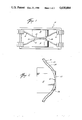
- FIG. 1 is a diagram of an evanescent optic coupler
- FIG. 2 depicts an optic fiber mounted on a lapping block
- FIG. 3 illustrates the method and apparatus for monitoring the lapping depth of optical flats
- FIG. 4 shows a laser as a light source.
- FIG. 1 illustrates a bi-directional evanescent optic coupler 10 consisting of optical connectors 12 coupled to respective ends of optic fibers such as 14.
- Optic fibers 14 are conformably mounted on a curved surface 16 of a lapping mandrel 18.
- Optic fiber flats are in intimate contact along line 20.
- FIG. 2 more clearly illustrates an optic fiber 14 consisting of a fiber cladding 22, and core 24, flushly mounted on curved surface 16 of lapping mandrel 18 by adhesive 26.
- Surface 20 represents the plane along which optic fiber cladding 22, and adhesive 26 are stripped away by lapping and polishing.
- FIG. 3 illustrates the method and apparatus for monitoring the lapping depth of optical flats.
- Optic fiber 14 is mounted to the curved surface 16 of lapping mandrel 18 as previously described.
- Mandrel 18 is mounted on a lapping fixture (not shown).
- the lapping fixture may be any suitable device for maintaining rigidity of lapping mandrels 18 during the lapping process.
- the lap (not shown) is backed away relative to optic fiber 14 and lapping mandrel 18.
- a source of radiant energy 28 is positioned within the lubricating fluid reservoir 30 directly above the fluid outlet 32.
- Lubricating fluid 34 transparent to the radiant energy flows out of outlet 32 in a laminar stream.
- a long-chain polymer such as polypropylene or other suitable additives may be mixed with the lubricating fluid to improve laminar flow from outlet 32.
- Fluid column 34 acts as an optical waveguide, directing radiant energy 36 from source 28 upon lapped surface 20.
- a portion of beam 36 is evanescently coupled between fluid column 34 into optic fiber 14 across surface 20.
- a light intensity monitor such as a photometer 38, measures the relative intensity level of transmitted radiant energy 36' propagating within optic fiber 14.
- a predetermined intensity level registered on monitor 38 indicates the proper lapping depth.
- collimation of radiant energy beam 36 may be accomplished by using a coherent beam laser 40 outside of lubricating fluid column 34 seen in FIG. 3.
- the wavelength of the radiation beam emitted by laser 40 may be of any desired value but preferably of a length that will be used in the finished optical system.
- the continuous flow of fluid 34 over optical flat 20 is needed only during the lapping process.
- a remaining residual film of lubricating fluid acts to polish the lapped surface on optical flat 20.
- the laser beam is directed at the lapped portion of the optical fiber at a desired angle of incidence to couple the laser beam into the optical fiber. The angle of incidence is best determined empirically.
- optic fiber 14 may be retained against the convex surface 16 of lapping mandrel 18 by means of a well-known vacuum chuck.
- the vacuum chuck can consist of a longitudinal groove of suitable radius incised in the convex surface 16. The groove is in fluid communication with a vacuum pump, which when activated, creates a vacuum between optic fiber 14 and lapping mandrel 18.
Abstract
Description
Claims (7)
Priority Applications (1)
| Application Number | Priority Date | Filing Date | Title |
|---|---|---|---|
| US06/647,226 US4630884A (en) | 1984-09-04 | 1984-09-04 | Method and apparatus for monitoring optical fiber lapping and polishing |
Applications Claiming Priority (1)
| Application Number | Priority Date | Filing Date | Title |
|---|---|---|---|
| US06/647,226 US4630884A (en) | 1984-09-04 | 1984-09-04 | Method and apparatus for monitoring optical fiber lapping and polishing |
Publications (1)
| Publication Number | Publication Date |
|---|---|
| US4630884A true US4630884A (en) | 1986-12-23 |
Family
ID=24596142
Family Applications (1)
| Application Number | Title | Priority Date | Filing Date |
|---|---|---|---|
| US06/647,226 Expired - Lifetime US4630884A (en) | 1984-09-04 | 1984-09-04 | Method and apparatus for monitoring optical fiber lapping and polishing |
Country Status (1)
| Country | Link |
|---|---|
| US (1) | US4630884A (en) |
Cited By (22)
| Publication number | Priority date | Publication date | Assignee | Title |
|---|---|---|---|---|
| US4904040A (en) * | 1987-06-10 | 1990-02-27 | Seiko Instruments Inc. | Optical waveguide coupler for monitoring |
| US4991922A (en) * | 1988-08-29 | 1991-02-12 | The Charles Stark Draper Laboratory, Inc. | Optical fiber coupler and method |
| US5106394A (en) * | 1990-10-01 | 1992-04-21 | The United States Of America As Represented By The Secretary Of The Navy | Fiber optic polishing system |
| US5136818A (en) * | 1990-10-01 | 1992-08-11 | The United States Of America As Represented By The Secretary Of The Navy | Method of polishing optical fiber |
| DE4228534A1 (en) * | 1992-08-27 | 1994-03-17 | Fraunhofer Ges Forschung | Coupling light into planar thin-film waveguide - using evanescent field of auxiliary waveguide pressed against coating-free planar waveguide |
| US5533155A (en) * | 1994-12-30 | 1996-07-02 | At&T Corp. | Evanescent field coupler |
| US5623567A (en) * | 1994-12-30 | 1997-04-22 | Lucent Technologies Inc. | Method for making an evanescent field coupler |
| US6191224B1 (en) | 1998-08-25 | 2001-02-20 | Molecular Optoelectronics Corporation | Dispersion-controlled polymers for broadband fiber optic devices |
| US6205280B1 (en) | 1998-08-25 | 2001-03-20 | Molecular Optoelectronics Corporation | Blockless fiber optic attenuators and attenuation systems employing dispersion controlled polymers |
| US6301426B1 (en) | 1999-03-16 | 2001-10-09 | Molecular Optoelectronics Corporation | Mechanically adjustable fiber optic attenuator and method employing same |
| US6374011B1 (en) * | 1998-08-25 | 2002-04-16 | Molecular Optoelectronics Corporation | Blockless techniques for simultaneous polishing of multiple fiber optics |
| US20020168170A1 (en) * | 1998-08-25 | 2002-11-14 | Molecular Optoelectronics Corporation | Blockless fiber optic attenuators and attenuation systems employing dispersion tailored polymers |
| US6483981B1 (en) | 2000-06-28 | 2002-11-19 | Molecular Optoelectronics Corp. | Single-channel attenuators |
| US6489399B1 (en) | 2000-07-31 | 2002-12-03 | Molecular Optoelectronics Corp. | Dye-appended polymers for broadband fiber optic devices |
| US6600854B2 (en) * | 2001-03-05 | 2003-07-29 | Evans & Sutherland Computer Corporation | Optical fiber polishing system with depth reference |
| US6611649B2 (en) | 2001-03-19 | 2003-08-26 | Molecular Optoelectronics Corporation | Variable optical attenuator with polarization maintaining fiber |
| US6681073B2 (en) | 2001-03-19 | 2004-01-20 | Molecular Optoelectronics Corporation | Fiber optic power control systems and methods |
| US7891818B2 (en) | 2006-12-12 | 2011-02-22 | Evans & Sutherland Computer Corporation | System and method for aligning RGB light in a single modulator projector |
| US8077378B1 (en) | 2008-11-12 | 2011-12-13 | Evans & Sutherland Computer Corporation | Calibration system and method for light modulation device |
| US8358317B2 (en) | 2008-05-23 | 2013-01-22 | Evans & Sutherland Computer Corporation | System and method for displaying a planar image on a curved surface |
| US8702248B1 (en) | 2008-06-11 | 2014-04-22 | Evans & Sutherland Computer Corporation | Projection method for reducing interpixel gaps on a viewing surface |
| US9641826B1 (en) | 2011-10-06 | 2017-05-02 | Evans & Sutherland Computer Corporation | System and method for displaying distant 3-D stereo on a dome surface |
Citations (4)
| Publication number | Priority date | Publication date | Assignee | Title |
|---|---|---|---|---|
| US3566172A (en) * | 1968-05-14 | 1971-02-23 | Rca Corp | Light deflection system |
| US4286839A (en) * | 1978-12-18 | 1981-09-01 | Original Hanau Heraeus Gmbh | Light directing control system, particularly for medical operating and diagnostic use |
| US4431260A (en) * | 1979-02-26 | 1984-02-14 | General Dynamics, Pomona Division | Method of fabrication of fiber optic coupler |
| US4588255A (en) * | 1982-06-21 | 1986-05-13 | The Board Of Trustees Of The Leland Stanford Junior University | Optical guided wave signal processor for matrix-vector multiplication and filtering |
-
1984
- 1984-09-04 US US06/647,226 patent/US4630884A/en not_active Expired - Lifetime
Patent Citations (4)
| Publication number | Priority date | Publication date | Assignee | Title |
|---|---|---|---|---|
| US3566172A (en) * | 1968-05-14 | 1971-02-23 | Rca Corp | Light deflection system |
| US4286839A (en) * | 1978-12-18 | 1981-09-01 | Original Hanau Heraeus Gmbh | Light directing control system, particularly for medical operating and diagnostic use |
| US4431260A (en) * | 1979-02-26 | 1984-02-14 | General Dynamics, Pomona Division | Method of fabrication of fiber optic coupler |
| US4588255A (en) * | 1982-06-21 | 1986-05-13 | The Board Of Trustees Of The Leland Stanford Junior University | Optical guided wave signal processor for matrix-vector multiplication and filtering |
Cited By (29)
| Publication number | Priority date | Publication date | Assignee | Title |
|---|---|---|---|---|
| US4904040A (en) * | 1987-06-10 | 1990-02-27 | Seiko Instruments Inc. | Optical waveguide coupler for monitoring |
| US4991922A (en) * | 1988-08-29 | 1991-02-12 | The Charles Stark Draper Laboratory, Inc. | Optical fiber coupler and method |
| US5106394A (en) * | 1990-10-01 | 1992-04-21 | The United States Of America As Represented By The Secretary Of The Navy | Fiber optic polishing system |
| US5136818A (en) * | 1990-10-01 | 1992-08-11 | The United States Of America As Represented By The Secretary Of The Navy | Method of polishing optical fiber |
| DE4228534A1 (en) * | 1992-08-27 | 1994-03-17 | Fraunhofer Ges Forschung | Coupling light into planar thin-film waveguide - using evanescent field of auxiliary waveguide pressed against coating-free planar waveguide |
| DE4228534C2 (en) * | 1992-08-27 | 2000-05-11 | Fraunhofer Ges Forschung | Method for analyzing a foreign substance |
| US5533155A (en) * | 1994-12-30 | 1996-07-02 | At&T Corp. | Evanescent field coupler |
| US5623567A (en) * | 1994-12-30 | 1997-04-22 | Lucent Technologies Inc. | Method for making an evanescent field coupler |
| US6374011B1 (en) * | 1998-08-25 | 2002-04-16 | Molecular Optoelectronics Corporation | Blockless techniques for simultaneous polishing of multiple fiber optics |
| US6785461B2 (en) | 1998-08-25 | 2004-08-31 | Molecular Optoelectronics Corp. | Blockless fiber optic attenuators and attenuation systems employing dispersion tailored polymers |
| US6268435B1 (en) | 1998-08-25 | 2001-07-31 | Molecular Optoelectronics Corporation | Dispersion-controlled polymers for broadband fiber optic devices |
| US6303695B1 (en) | 1998-08-25 | 2001-10-16 | Molecular Optoelectronics Corporation | Dispersion-controlled polymers for broadband fiber optic devices |
| US6335998B2 (en) | 1998-08-25 | 2002-01-01 | Molecular Optoelectronics Corporation | Blockless fiber optic attenuators and attenuation systems employing dispersion tailored polymers |
| US6191224B1 (en) | 1998-08-25 | 2001-02-20 | Molecular Optoelectronics Corporation | Dispersion-controlled polymers for broadband fiber optic devices |
| US6444756B2 (en) | 1998-08-25 | 2002-09-03 | Molecular Optoelectronics Corporation | Dispersion-controlled polymers for broad band fiber optic devices |
| US20020168170A1 (en) * | 1998-08-25 | 2002-11-14 | Molecular Optoelectronics Corporation | Blockless fiber optic attenuators and attenuation systems employing dispersion tailored polymers |
| US6205280B1 (en) | 1998-08-25 | 2001-03-20 | Molecular Optoelectronics Corporation | Blockless fiber optic attenuators and attenuation systems employing dispersion controlled polymers |
| US6301426B1 (en) | 1999-03-16 | 2001-10-09 | Molecular Optoelectronics Corporation | Mechanically adjustable fiber optic attenuator and method employing same |
| US6483981B1 (en) | 2000-06-28 | 2002-11-19 | Molecular Optoelectronics Corp. | Single-channel attenuators |
| US6489399B1 (en) | 2000-07-31 | 2002-12-03 | Molecular Optoelectronics Corp. | Dye-appended polymers for broadband fiber optic devices |
| US6600854B2 (en) * | 2001-03-05 | 2003-07-29 | Evans & Sutherland Computer Corporation | Optical fiber polishing system with depth reference |
| US6681073B2 (en) | 2001-03-19 | 2004-01-20 | Molecular Optoelectronics Corporation | Fiber optic power control systems and methods |
| US6611649B2 (en) | 2001-03-19 | 2003-08-26 | Molecular Optoelectronics Corporation | Variable optical attenuator with polarization maintaining fiber |
| US7891818B2 (en) | 2006-12-12 | 2011-02-22 | Evans & Sutherland Computer Corporation | System and method for aligning RGB light in a single modulator projector |
| US8358317B2 (en) | 2008-05-23 | 2013-01-22 | Evans & Sutherland Computer Corporation | System and method for displaying a planar image on a curved surface |
| US8702248B1 (en) | 2008-06-11 | 2014-04-22 | Evans & Sutherland Computer Corporation | Projection method for reducing interpixel gaps on a viewing surface |
| US8077378B1 (en) | 2008-11-12 | 2011-12-13 | Evans & Sutherland Computer Corporation | Calibration system and method for light modulation device |
| US9641826B1 (en) | 2011-10-06 | 2017-05-02 | Evans & Sutherland Computer Corporation | System and method for displaying distant 3-D stereo on a dome surface |
| US10110876B1 (en) | 2011-10-06 | 2018-10-23 | Evans & Sutherland Computer Corporation | System and method for displaying images in 3-D stereo |
Similar Documents
| Publication | Publication Date | Title |
|---|---|---|
| US4630884A (en) | Method and apparatus for monitoring optical fiber lapping and polishing | |
| EP0074789B1 (en) | Fiber optic directional coupler | |
| US4431260A (en) | Method of fabrication of fiber optic coupler | |
| US4387954A (en) | Method for fabricating an optical waveguide evanescent wave coupler having an interleaved film | |
| US5136818A (en) | Method of polishing optical fiber | |
| TWI230811B (en) | Devices and methods for side-coupling optical fibers to optoelectronic components | |
| KR100265789B1 (en) | Method for manual aligning the optical fibers | |
| US4779945A (en) | Directional coupler utilizing biconically tapered optical fibers and a method of making same | |
| EP0798579A1 (en) | Optical integrated circuit having passively aligned fibers | |
| US10094989B2 (en) | Optical device, optical processing device, and method of producing the optical device | |
| US5526452A (en) | Planar optical waveguides with low back reflection pigtailing | |
| US4398795A (en) | Fiber optic tap and method of fabrication | |
| US4325605A (en) | Branching element for monomode light waveguides and the method of manufacture | |
| US4533208A (en) | Evanescent-wave star coupler on a substrate | |
| US5106394A (en) | Fiber optic polishing system | |
| US4165914A (en) | Access coupler and duplex coupler for single multimode fiber transmission line | |
| US4439005A (en) | Branching element for optical waveguides | |
| Cordaro et al. | Precision fabrication of D-shaped single-mode optical fibers by in situ monitoring | |
| EP0136761B1 (en) | Method and device for coupling an optical signal from a first light guide into a second light guide | |
| KR20010022335A (en) | Planar optical device connector and method for making same | |
| TW493090B (en) | Micro-fiber coupler and the manufacturing method thereof | |
| US9597765B2 (en) | Fiber optic dielectric waveguide structure for modal multiplexed communication and method of manufacture | |
| JPH06130242A (en) | Method for connecting two optical fiber cables by splicing | |
| JPH09159865A (en) | Connection structure of optical waveguide | |
| JP2003294953A (en) | Optical device and method for manufacturing the same |
Legal Events
| Date | Code | Title | Description |
|---|---|---|---|
| AS | Assignment |
Owner name: WESTERN GEOPHYSICAL COMPANY OF AMERICA A DE CORP. Free format text: ASSIGNMENT OF ASSIGNORS INTEREST.;ASSIGNOR:JUBINSKI, PAUL;REEL/FRAME:004310/0579 Effective date: 19840830 |
|
| STCF | Information on status: patent grant |
Free format text: PATENTED CASE |
|
| AS | Assignment |
Owner name: WESTERN ATLAS INTERNATIONAL, INC., 10,001 RICHMOND Free format text: ASSIGNMENT OF ASSIGNORS INTEREST.;ASSIGNOR:WESTERN GEOPHYSICAL COMPANY OF AMERICA, A CORP OF DE;REEL/FRAME:004725/0239 Effective date: 19870430 |
|
| FEPP | Fee payment procedure |
Free format text: PAYOR NUMBER ASSIGNED (ORIGINAL EVENT CODE: ASPN); ENTITY STATUS OF PATENT OWNER: LARGE ENTITY |
|
| FPAY | Fee payment |
Year of fee payment: 4 |
|
| FPAY | Fee payment |
Year of fee payment: 8 |
|
| AS | Assignment |
Owner name: I/O EXPLORATION PRODUCTS, INC., TEXAS Free format text: ASSIGNMENT OF ASSIGNORS INTEREST;ASSIGNOR:WESTERN ATLAS INTERNATIONAL, INC.;REEL/FRAME:007644/0138 Effective date: 19950630 |
|
| AS | Assignment |
Owner name: I/O EXPLORATION PRODUCTS (U.S.A), INC., TEXAS Free format text: CORRECTED ASSIGNMENT;ASSIGNOR:WESTERN ATLAS INTERNATIONAL, INC.;REEL/FRAME:007815/0841 Effective date: 19950630 |
|
| FPAY | Fee payment |
Year of fee payment: 12 |
|
| AS | Assignment |
Owner name: INPUT/OUTPUT, INC., TEXAS Free format text: ASSIGNMENT OF ASSIGNORS INTEREST;ASSIGNOR:I/O EXPLORATION PRODUCTS (U.S.A.), INC.;REEL/FRAME:009245/0506 Effective date: 19980212 |