US4604697A - Body imaging using vectorial addition of acoustic reflection to achieve effect of scanning beam continuously focused in range - Google Patents
Body imaging using vectorial addition of acoustic reflection to achieve effect of scanning beam continuously focused in range Download PDFInfo
- Publication number
- US4604697A US4604697A US06/520,573 US52057383A US4604697A US 4604697 A US4604697 A US 4604697A US 52057383 A US52057383 A US 52057383A US 4604697 A US4604697 A US 4604697A
- Authority
- US
- United States
- Prior art keywords
- acoustic energy
- output signals
- signals
- transducers
- image
- Prior art date
- Legal status (The legal status is an assumption and is not a legal conclusion. Google has not performed a legal analysis and makes no representation as to the accuracy of the status listed.)
- Expired - Lifetime
Links
Images

Classifications
-
- G—PHYSICS
- G10—MUSICAL INSTRUMENTS; ACOUSTICS
- G10K—SOUND-PRODUCING DEVICES; METHODS OR DEVICES FOR PROTECTING AGAINST, OR FOR DAMPING, NOISE OR OTHER ACOUSTIC WAVES IN GENERAL; ACOUSTICS NOT OTHERWISE PROVIDED FOR
- G10K11/00—Methods or devices for transmitting, conducting or directing sound in general; Methods or devices for protecting against, or for damping, noise or other acoustic waves in general
- G10K11/18—Methods or devices for transmitting, conducting or directing sound
- G10K11/26—Sound-focusing or directing, e.g. scanning
- G10K11/34—Sound-focusing or directing, e.g. scanning using electrical steering of transducer arrays, e.g. beam steering
- G10K11/341—Circuits therefor
- G10K11/346—Circuits therefor using phase variation
-
- G—PHYSICS
- G01—MEASURING; TESTING
- G01S—RADIO DIRECTION-FINDING; RADIO NAVIGATION; DETERMINING DISTANCE OR VELOCITY BY USE OF RADIO WAVES; LOCATING OR PRESENCE-DETECTING BY USE OF THE REFLECTION OR RERADIATION OF RADIO WAVES; ANALOGOUS ARRANGEMENTS USING OTHER WAVES
- G01S15/00—Systems using the reflection or reradiation of acoustic waves, e.g. sonar systems
- G01S15/88—Sonar systems specially adapted for specific applications
- G01S15/89—Sonar systems specially adapted for specific applications for mapping or imaging
- G01S15/8906—Short-range imaging systems; Acoustic microscope systems using pulse-echo techniques
- G01S15/8977—Short-range imaging systems; Acoustic microscope systems using pulse-echo techniques using special techniques for image reconstruction, e.g. FFT, geometrical transformations, spatial deconvolution, time deconvolution
-
- G—PHYSICS
- G01—MEASURING; TESTING
- G01S—RADIO DIRECTION-FINDING; RADIO NAVIGATION; DETERMINING DISTANCE OR VELOCITY BY USE OF RADIO WAVES; LOCATING OR PRESENCE-DETECTING BY USE OF THE REFLECTION OR RERADIATION OF RADIO WAVES; ANALOGOUS ARRANGEMENTS USING OTHER WAVES
- G01S7/00—Details of systems according to groups G01S13/00, G01S15/00, G01S17/00
- G01S7/52—Details of systems according to groups G01S13/00, G01S15/00, G01S17/00 of systems according to group G01S15/00
- G01S7/52017—Details of systems according to groups G01S13/00, G01S15/00, G01S17/00 of systems according to group G01S15/00 particularly adapted to short-range imaging
- G01S7/52046—Techniques for image enhancement involving transmitter or receiver
Definitions
- the present invention relates to improvements in forming images of objects, or portions of objects, which are not accessible to conventional methods of optical observation.
- the invention is particularly applicable to forming such images of the interior of the human body.
- This signal processing of the transducer outputs has involved applying phase shifts (if operating in the narrowband, or CW mode), or time delays (if operating in the wideband, or pulsed mode), to the outputs of different ones of these transducers, which were so proportioned that these outputs would "line up” and add together to produce an enlarged combined output when reflected radiation picked up by the transducers emanated from a specific point within the irradiated body portion.
- phase shifts if operating in the narrowband, or CW mode
- time delays if operating in the wideband, or pulsed mode
- an intensified combined output signal was produced from reflection points (generally called targets), while the combined output signal from non-reflecting points was comparatively suppressed. This made it possible to visually display the targets, e.g. on a cathode ray tube.
- a plurality of electro-acoustic transducers are positioned in the vicinity of the body to be observed.
- Acoustic radiation is projected upon the body sequentially from different ones, or from different sub-sets, of the transducers, this projection being made so that each projection covers the entire body to be observed, rather than only selected portions as would be the case with a projected scanning beam of the prior art.
- Any reflected acoustic radiation is picked up by the transducers and the electrical signals produced in response thereto are subjected to signal processing.
- This signal processing involves the following.
- the signals from different transducers are phase shifted (if dealt with in the frequency domain), or time delayed (if dealt with in the time domain) so that, if a target is present at a particular point within the body, the amplitude envelopes of these signals will additively combine, and thereby provide a relatively large and conspicuous signal, while signals from other points will not additively combine, but will on the contrary tend to cancel and thereby be rendered less conspicuous relative to the target signal.
- the signal processing in accordance with the present invention is substantially the same as in some prior systems.
- the output signals from the several transducers which are produced in response to consecutive projections from different ones, or from different sub-sets of the transducers and each of which output signals has been processed as described above--including the preservation of the phase (or time delay) information--are further processed, to additively combine them in vectorial manner, i.e. in accordance with both the amplitude and phase (or time delay) information obtained through the prior signal processing.
- the combined signals resulting from this further processing are then utilized to create the visual display of the image.
- This further processing also differs from the prior art, which did not perform such further processing at all. It can be shown that the signals which are ultimately obtained by proceeding as described above are analogous to those which would have been obtained if the signals picked-up by the transducers (from the body) had been processed in the same manner as in the prior art--namely by additively combining them and then discarding the phase (or time delay) information--but in addition the energy projected upon the body had been formed into a continuously range focussed scanning beam.
- FIG. 1 is an overall block diagram of apparatus embodying the invention.
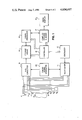
- FIG. 2 is a block diagram of such an embodiment utilizing computerized signal processing.
- kR pl 2 ⁇ / ⁇ , where ⁇ is the wavelength of the acoustic energy and R pl is the distance from the p th pixel to the l th transducer.
- Expression (4) can therefore be rewritten as follows: ##EQU5##
- Expression (6) shows that, in order to obtain I(p) it is not necessary to perform two separate steps, namely to first obtain N different complex image representative signals (per expression 2) and then sum them (per expression 3). Rather, the double summation (per expression 6) can be performed in one single step to obtain I(p).
- the data gathering time is only a function of the number of transducers used and of the depth of view into the body. This data gathering time does not depend upon the number of pixels to be displayed in the ultimate image. That is because the entire body is irradiated with acoustic energy at the same time, rather than point-by-point, in sequence. Also, the problems of implementing a scanning, focused transmitting beam are completely eliminated.
- FIG. 1 of the drawings shows a body 10 which is to be imaged in accordance with the present invention.
- Elements 11 represent the transducers for both transmitting and receiving acoustic energy. While only seven transducers 11 have been shown in FIG. 1, it will be understood that a larger number will typically be used, as indicated by the dotted line bridging the gap between the three upper and the four lower transducers 11.
- One or more of transducers 11, as determined by multiplexer 12 is energized to emit ultrasonic energy by means of energizer 13. From reflections within body 10, there is produced reflected acoustic energy, some of which is picked-up by the transducers 11, which respond to produce corresponding electrical output signals.
- These output signals are supplied to storage means 14. Preferably, these output signals are supplied in digital form, derived from the transducer output signals by A/D converter 15.
- one or more different transducers 11 are selected by the multiplexer 12 and energized by energizer 13. In this way, another set of output signals from the transducers 11 is obtained and stored in storage means 14, and so forth consecutively. Each set of signals so obtained and stored is then processed within signal processing means 16 of FIG. 1, in conformity with expression (1), above, and the resultant complex image representative signals are stored in intermediate storage and adder means 17 of FIG. 1.
- the signal processing means 16 comprises phase shifters and adders. It imparts to the signals stored in storage means 14 the phase shifts which are appropriate in accordance with expression (1), above, and also adds these signals together. Its activity is controlled by the control means 18.
- the signals so obtained are supplied to intermediate storage and adder means 17.
- the "complex" nature of the signals is preserved, that is, both amplitude and phase information is preserved.
- this is strikingly different from prior systems, in which, once phase shifts and additions such as described with reference to signal processing menas 16 has been accomplished, only the amplitude information about the resultant signals was preserved, while the phase information was discarded, and not used in subsequent processing.
- the complex signals are then vectorially added, in the manner described by expression (3), above.
- the so-produced signals are then used to form the image to be displayed by display means 19.
- the signal from storage and adder means 17, for each image-representative point of body 10 is identified with a set of geometric coordinates corresponding to the same point within that body and, based on this identification is displayed electronically on a cathode ray screen of display means 19.
- the individual components which make up the over-all system in FIG. 1 may be, in themselves, of entirely conventional form.
- the transducers 11 are entirely conventional electro-acoustic components.
- they may be held in the desired array configuration by being embedded in a suitable conventional mounting. This enables them to be applied directly to the surface which encloses the body to be observed. In this way, intimacy of acoustic coupling with the observed body is desirably promoted.
- Transducer energizer 13 may be a conventional oscillator, and timing signal generator 20 may be a conventional circuit capable of turning the oscillator 13 on and off, and directing its output either to multiplexer 12 or to A/D converter 15 as well as of controlling the operation of A/D converter 15 so as to function in proper timing coordination with energizer 13.
- the A/D converter 15 itself may also be of conventional form. If necessary for operation at the rates appropriate for the system, several individual A/D converters may have to be connected in parallel in known manner.
- the storage means 14 may likewise be of conventional form. As previously discussed, this storage means must be capable of storing the digital signals produced by A/D converter 15, and of supplying them from storage to signal processing means 16.
- the signal processing means 16 may also be of conventional form for performing the specific signal processing operations previously described with reference to expression (1), above. All of those operations will be readily recognized to be entirely conventional, in themselves.
- the storage and adder means 17 may be of conventional form for performing the operations of initial storage of the complex signals from signal processing means 16, followed by vectorial addition of these signals in accordance with expression (3), above.
- the control means 18 which causes all this to happen is also completely conventional in digital technology. It will include a pre-programmed sequence of control functions to activate the various sequential processes within the signal processing means 16, and the supplying of the input signals necessary for the purpose from storage means 14, and for the addition processes within storage and adder means 17 and the withdrawal of stored signals for that purpose. It will also provide the information concerning the relationships between the geometric coordinates of the transducer locations and the body points, and between these body points and the image display points, which determines the visible pattern in which any given selection of body image points is displayed as a complete image by use of image display means 19. This information may be provided by suitable conventional storage means, such as a magnetic disk memory.
- the image display 19 may be of conventional form, e.g. a cathode ray tube display on whose CRT screen there is formed an image whose intensity (brightness) varies in accordance with variations in the reflectivity of the various body points or targets being displayed.
- the frequency of the acoustic energy used can be varied within wide limits, the rate at which the A/D conversion takes place can be varied, and so can the number of quantization levels and resulting bits in the digital signals which are produced.
- the transducers 11 may be used for projection one at a time, or more than one such transducer may be used at the same time, in order to increase the amount of energy reaching the object. However, more than one transducer may be used only provided that no focusing effect is thereby produced within the desired field of view.
- the number of transducers used can be varied, and so can their positions within the array which is formed by them. Indeed, it is not essential that all the transducers of an intended array be physically present.
- the transducer array can also be realized synthetically by moving a lesser number to different locations and storing the information obtained at each location until that from all locations has been accumulated. Under those circumstances, of course, the complete image will be obtained less rapidly because, if a desired array of N transducers is to be synthesized from a lesser number of n transducers, then N 2 /n transmissions and corresponding receptions of reflections will have to be awaited, whereas N such transmissions and receptions would have sufficed if the full array of N transducers had been simultaneously used.
- transducers may be arranged in a plane, rather than in a line. If so, it becomes possible to provide the desired continuous range focus in two dimensions.
- this can be performed either after storage, as in FIG. 1, or on-line.
- the body 10 need not be some portion of the human anatomy. Rather the invention is also applicable to non-destructive testing using ultrasound.
- FIG. 1 The explanation of the embodiment of FIG. 1 has been predicated on the use of narrow-band transmissions and corresponding reflections. However, wideband pulses can also be used. Under those circumstances, it would ideally be desirable to perform the operations represented by the various expressions presented above for each frequency component in the spectrum of the pulses. This would make it possible, in effect, to obtain an image corresponding to each such frequency component (per expressions (4) and (6), above). To accomplish this, there is first stored the output signal from each transducer 11. This may be done by sampling and digitizing the output signal using A/D converter 15 and storing the numbers coming out of the A/D converter 15.
- F lm (t) be the continuous time output of the lth transducer 11 when the mth transducer is used as a transmitter.
- the final image representative signal I(p) of the pth pixel is given by the following expression ##EQU6## where T 1 is generally equal to T o , and T is the duration over which the integration is performed. This duration T is generally one pulse duration long.
- I(p) is given by the following expression ##EQU7## where F lm (n) represents the nth sample of the signal F lm (t), n.sub. ⁇ is the number of samples in the duration ⁇ lmp ,n 1 is generally the number of samples in the suration T o , and n 2 is generally equal to n 1 plus the number of samples in the pulse duration. ##EQU8##
- FIG. 2 illustrates a computer-based embodiment of the invention, utilizing wideband pulses as described immediately above.
- the transducer energizer and multiplexer which correspond to components 13 and 12 in the embodiment of FIG. 1, have been shown as a single unit 30.
- a single connection has been shown to the electro-acoustic transducers (not shown), and back from the transducers, although it will be understood that, as in FIG. 1, there are really separate connections to and from each transducer, with signals from exciter and multiplexer applied separately and in time-multiplexed sequence to the different transducers.
- the output signals from the transducers are again sampled and digitized employing a data acquisition system 31, Biomation Model 8100. Through an interface 32, Digital Equipment Corp. Model DR VII-3, these data are supplied to the Q-Bus 33 interconnecting a central processor unit 34, Digital Equipment Corp. Model LSI 11/23, a random access memory 35 having 256 kilobyte capacity, a hard disk memory 36 having 40 megabyte capacity, an array processor 37, Sky Computers Model SKYMNK, a display 38, Advanced Electronics Devices Model 512, and a terminal 39 for manual control of the overall system.
- the digitized signals obtained from data acquisition system 31 are stored in hard disk memory 36, where each storage location represents the sample obtained at one particular time.
- the appropriate time delays, as determined in accordance with the expressions (7) and (8), above, are imparted to these stored signals by moving them up or down in the disk memory.
- THe intensity of any pixel is then calculated in accordance with the said expressions and displayed on display 38.
- LIN50 creates the complex image representative output signal (per expression 1) for each transmitting element at various frequencies.
- NDATA program creates the final image representative signal (per expression 3) at various frequencies. These final image representative signals at various frequencies are also further added together in the program before displaying the image.
- the programs involve use of the following outside subroutines: INITPAGE, PAGE, SKYMNK array processor routines (VINIT, VI2SP, VSET, VFFTW, VMGSQW, VWAIT, VSMUL, VADDW, VWAIT), and graphic display routines (BSO, SZR, MOV, WRD) supplied by Advanced Electronics Design, Inc., to be used with their graphics display terminal AED 512.
- the details of the display routines are available in the manual, "Terminal Access Package (TAP) User's Guide PDP-11 Version", supplied by Advanced Electronics Design, Inc., Sunnyvale, Calif.
- Subroutines INITPAGE and PAGE are written in assembly language and are used to address different locations of the computer memory (bank switching).
Abstract
Description
I(p)=A·|(Receiving Pattern)|.sup.2 (5)
Claims (16)
Priority Applications (6)
| Application Number | Priority Date | Filing Date | Title |
|---|---|---|---|
| US06/520,573 US4604697A (en) | 1983-08-05 | 1983-08-05 | Body imaging using vectorial addition of acoustic reflection to achieve effect of scanning beam continuously focused in range |
| EP84903131A EP0155280B1 (en) | 1983-08-05 | 1984-08-02 | Body imaging using vectorial addition of acoustic reflections to achieve effect of scanning beam continuously focused in range |
| AU33128/84A AU3312884A (en) | 1983-08-05 | 1984-08-02 | Body imaging using signal processing to achieve effect of scanning beam continuously focused in range |
| PCT/US1984/001231 WO1985000889A1 (en) | 1983-08-05 | 1984-08-02 | Body imaging using vectorial addition of acoustic reflections to achieve effect of scanning beam continuously focused in range |
| JP59503108A JPS60502141A (en) | 1983-08-05 | 1984-08-02 | Human body imaging system and method using signal processing to achieve the effect of a continuously focused scanning beam in a range |
| DE8484903131T DE3479055D1 (en) | 1983-08-05 | 1984-08-02 | Body imaging using vectorial addition of acoustic reflections to achieve effect of scanning beam continuously focused in range |
Applications Claiming Priority (1)
| Application Number | Priority Date | Filing Date | Title |
|---|---|---|---|
| US06/520,573 US4604697A (en) | 1983-08-05 | 1983-08-05 | Body imaging using vectorial addition of acoustic reflection to achieve effect of scanning beam continuously focused in range |
Publications (1)
| Publication Number | Publication Date |
|---|---|
| US4604697A true US4604697A (en) | 1986-08-05 |
Family
ID=24073189
Family Applications (1)
| Application Number | Title | Priority Date | Filing Date |
|---|---|---|---|
| US06/520,573 Expired - Lifetime US4604697A (en) | 1983-08-05 | 1983-08-05 | Body imaging using vectorial addition of acoustic reflection to achieve effect of scanning beam continuously focused in range |
Country Status (6)
| Country | Link |
|---|---|
| US (1) | US4604697A (en) |
| EP (1) | EP0155280B1 (en) |
| JP (1) | JPS60502141A (en) |
| AU (1) | AU3312884A (en) |
| DE (1) | DE3479055D1 (en) |
| WO (1) | WO1985000889A1 (en) |
Cited By (69)
| Publication number | Priority date | Publication date | Assignee | Title |
|---|---|---|---|---|
| US4733562A (en) * | 1985-07-15 | 1988-03-29 | Siemens Aktiengesellschaft | Method and apparatus for ultrasonic scanning of an object |
| US4809184A (en) * | 1986-10-22 | 1989-02-28 | General Electric Company | Method and apparatus for fully digital beam formation in a phased array coherent imaging system |
| DE3831537A1 (en) * | 1987-09-21 | 1989-04-06 | Gen Electric | METHOD AND ARRANGEMENT FOR ADAPTIVELY REDUCING PHASE ABERRATION EFFECTS |
| US4858151A (en) * | 1986-09-29 | 1989-08-15 | Kabushiki Kaisha Toshiba | Data processing device for use in scintillation camera apparatus |
| WO1990012540A1 (en) * | 1989-04-20 | 1990-11-01 | National Fertility Institute | Apparatus and method for generating echographic images |
| US5172597A (en) * | 1990-11-14 | 1992-12-22 | General Electric Company | Method and application for measuring sound power emitted by a source in a background of ambient noise |
| US5187687A (en) * | 1985-06-20 | 1993-02-16 | Kontron Instruments Holding N.V. | Production of images |
| US5278757A (en) * | 1991-11-15 | 1994-01-11 | The Trustees Of The University Of Pennsylvania | Synthetic aperture ultrasonic imaging system using a minimum or reduced redundancy phased array |
| US5383457A (en) * | 1987-04-20 | 1995-01-24 | National Fertility Institute | Method and apparatus for processing images |
| US5437281A (en) * | 1992-01-14 | 1995-08-01 | Diasonics Ultrasound, Inc. | Direct demodulation in ultrasound instruments |
| US5526325A (en) * | 1995-09-21 | 1996-06-11 | The United States Of America As Represented By The Secretary Of The Navy | Steerable beamformer |
| US5555514A (en) * | 1992-07-20 | 1996-09-10 | Ge Yokogawa Medical Systems, Limited | Method of and apparatus for generating doppler sounds |
| US5951479A (en) * | 1998-09-29 | 1999-09-14 | General Electric Company | Method and apparatus for synthetic transmit aperture imaging |
| US6009755A (en) * | 1996-11-08 | 2000-01-04 | Mitsubishi Denki Kabushiki Kaisha | Ultrasonic transceiver displaying modified B scope |
| US6056693A (en) * | 1999-08-16 | 2000-05-02 | General Electric Company | Ultrasound imaging with synthetic transmit focusing |
| EP1028324A3 (en) * | 1999-02-09 | 2001-07-18 | Medison Co., Ltd. | Medical digital ultrasonic imaging apparatus capable of storing and reusing radio-frequency (RF) ultrasound pulse echoes |
| WO2003093863A1 (en) * | 2002-04-30 | 2003-11-13 | Koninklijke Philips Electronics N.V. | Synthetically focused ultrasonic diagnostic imaging system for tissue and flow imaging |
| US6702745B1 (en) * | 1999-01-21 | 2004-03-09 | David Smythe | 3D/4D ultrasound imaging system |
| US20070161904A1 (en) * | 2006-11-10 | 2007-07-12 | Penrith Corporation | Transducer array imaging system |
| US20070213615A1 (en) * | 1999-08-20 | 2007-09-13 | Mclaughlin Glen | Broad-beam imaging |
| US20080114245A1 (en) * | 2006-11-10 | 2008-05-15 | Randall Kevin S | Transducer array imaging system |
| US20080114255A1 (en) * | 2006-11-10 | 2008-05-15 | Penrith Corporation | Transducer array imaging system |
| US20080114253A1 (en) * | 2006-11-10 | 2008-05-15 | Penrith Corporation | Transducer array imaging system |
| US20080114249A1 (en) * | 2006-11-10 | 2008-05-15 | Penrith Corporation | Transducer array imaging system |
| US20080114252A1 (en) * | 2006-11-10 | 2008-05-15 | Penrith Corporation | Transducer array imaging system |
| US20080114239A1 (en) * | 2006-11-10 | 2008-05-15 | Penrith Corporation | Transducer array imaging system |
| US20080112265A1 (en) * | 2006-11-10 | 2008-05-15 | Penrith Corporation | Transducer array imaging system |
| US20080114241A1 (en) * | 2006-11-10 | 2008-05-15 | Penrith Corporation | Transducer array imaging system |
| US20080110261A1 (en) * | 2006-11-10 | 2008-05-15 | Penrith Corporation | Transducer array imaging system |
| US20080114247A1 (en) * | 2006-11-10 | 2008-05-15 | Penrith Corporation | Transducer array imaging system |
| US20080110266A1 (en) * | 2006-11-10 | 2008-05-15 | Penrith Corporation | Transducer array imaging system |
| US20080146922A1 (en) * | 2006-10-24 | 2008-06-19 | Zonare Medical Systems, Inc. | Control of user interfaces and displays for portable ultrasound unit and docking station |
| US20080194962A1 (en) * | 2007-02-08 | 2008-08-14 | Randall Kevin S | Methods for verifying the integrity of probes for ultrasound imaging systems |
| US20080194963A1 (en) * | 2007-02-08 | 2008-08-14 | Randall Kevin S | Probes for ultrasound imaging systems |
| US20080194961A1 (en) * | 2007-02-08 | 2008-08-14 | Randall Kevin S | Probes for ultrasound imaging systems |
| US20080194964A1 (en) * | 2007-02-08 | 2008-08-14 | Randall Kevin S | Ultrasound imaging systems |
| US20080194960A1 (en) * | 2007-02-08 | 2008-08-14 | Randall Kevin S | Probes for ultrasound imaging systems |
| US20100189329A1 (en) * | 2004-10-07 | 2010-07-29 | Zonare Medical Systems Inc. | Ultrasound Imaging System Parameter Optimization Via Fuzzy Logic |
| CN101664321B (en) * | 2009-09-07 | 2011-06-15 | 无锡祥生科技有限公司 | Group sound velocity real-time adjustable ultrasound diagnostic equipment and wave beam synthesis method thereof |
| US8002705B1 (en) | 2005-07-22 | 2011-08-23 | Zonaire Medical Systems, Inc. | Continuous transmit focusing method and apparatus for ultrasound imaging system |
| US20120075956A1 (en) * | 2010-09-29 | 2012-03-29 | Lockheed Martin Corporation | Mag-phase process |
| WO2012049124A2 (en) | 2010-10-11 | 2012-04-19 | B-K Medical Aps | Methods and systems for producing compounded ultrasound images |
| US8220334B2 (en) | 2006-11-10 | 2012-07-17 | Penrith Corporation | Transducer array imaging system |
| WO2012107370A1 (en) | 2011-02-07 | 2012-08-16 | Super Sonic Imagine | An imaging device with image acquisition rate optimization |
| US20130182539A1 (en) * | 2012-01-13 | 2013-07-18 | Texas Instruments Incorporated | Multipath reflection processing in ultrasonic gesture recognition systems |
| US8499634B2 (en) | 2006-11-10 | 2013-08-06 | Siemens Medical Solutions Usa, Inc. | Transducer array imaging system |
| US8784318B1 (en) | 2005-07-22 | 2014-07-22 | Zonare Medical Systems, Inc. | Aberration correction using channel data in ultrasound imaging system |
| US9060669B1 (en) | 2007-12-20 | 2015-06-23 | Zonare Medical Systems, Inc. | System and method for providing variable ultrasound array processing in a post-storage mode |
| WO2014146022A3 (en) * | 2013-03-15 | 2015-11-26 | Guided Therapy Systems Llc | Ultrasound treatment device and methods of use |
| US9339256B2 (en) | 2007-10-01 | 2016-05-17 | Maui Imaging, Inc. | Determining material stiffness using multiple aperture ultrasound |
| US9345455B2 (en) | 2006-05-12 | 2016-05-24 | Koninklijke Philips Electronics N.V. | Ultrasonic synthetic transmit focusing with motion compensation |
| US9420994B2 (en) | 2006-10-25 | 2016-08-23 | Maui Imaging, Inc. | Method and apparatus to produce ultrasonic images using multiple apertures |
| US9510806B2 (en) | 2013-03-13 | 2016-12-06 | Maui Imaging, Inc. | Alignment of ultrasound transducer arrays and multiple aperture probe assembly |
| US9526475B2 (en) | 2006-09-14 | 2016-12-27 | Maui Imaging, Inc. | Point source transmission and speed-of-sound correction using multi-aperture ultrasound imaging |
| US9572549B2 (en) | 2012-08-10 | 2017-02-21 | Maui Imaging, Inc. | Calibration of multiple aperture ultrasound probes |
| US9582876B2 (en) | 2006-02-06 | 2017-02-28 | Maui Imaging, Inc. | Method and apparatus to visualize the coronary arteries using ultrasound |
| US9668714B2 (en) | 2010-04-14 | 2017-06-06 | Maui Imaging, Inc. | Systems and methods for improving ultrasound image quality by applying weighting factors |
| US9788813B2 (en) | 2010-10-13 | 2017-10-17 | Maui Imaging, Inc. | Multiple aperture probe internal apparatus and cable assemblies |
| WO2017220354A1 (en) | 2016-06-23 | 2017-12-28 | Koninklijke Philips N.V. | Rapid synthetic focus ultrasonic imaging with large linear arrays |
| US9883848B2 (en) | 2013-09-13 | 2018-02-06 | Maui Imaging, Inc. | Ultrasound imaging using apparent point-source transmit transducer |
| US9986969B2 (en) | 2012-08-21 | 2018-06-05 | Maui Imaging, Inc. | Ultrasound imaging system memory architecture |
| US10206662B2 (en) | 2009-04-14 | 2019-02-19 | Maui Imaging, Inc. | Calibration of ultrasound probes |
| US10226234B2 (en) | 2011-12-01 | 2019-03-12 | Maui Imaging, Inc. | Motion detection using ping-based and multiple aperture doppler ultrasound |
| US10401493B2 (en) | 2014-08-18 | 2019-09-03 | Maui Imaging, Inc. | Network-based ultrasound imaging system |
| WO2020049088A1 (en) | 2018-09-07 | 2020-03-12 | Koninklijke Philips N.V. | High quality high frame rate ultrasound imaging with diverging transmit beams |
| WO2020049012A1 (en) | 2018-09-07 | 2020-03-12 | Koninklijke Philips N.V. | 3d ultrasound imaging with broadly focused transmit beams at a high frame rate of display |
| US10617384B2 (en) | 2011-12-29 | 2020-04-14 | Maui Imaging, Inc. | M-mode ultrasound imaging of arbitrary paths |
| US10835208B2 (en) | 2010-04-14 | 2020-11-17 | Maui Imaging, Inc. | Concave ultrasound transducers and 3D arrays |
| US10856846B2 (en) | 2016-01-27 | 2020-12-08 | Maui Imaging, Inc. | Ultrasound imaging with sparse array probes |
Families Citing this family (5)
| Publication number | Priority date | Publication date | Assignee | Title |
|---|---|---|---|---|
| US4815047A (en) * | 1986-06-20 | 1989-03-21 | Hewlett-Packard Company | Synthetic focus annular array transducer |
| GB9014544D0 (en) * | 1990-06-29 | 1990-08-22 | Univ Heriot Watt | Methods and apparatus for acoustic holographic imaging in marine and other acoustic remote sensing equipment |
| GB2268806B (en) * | 1992-07-14 | 1997-02-26 | Intravascular Res Ltd | Methods and apparatus for the examination and treatment of internal organs |
| GB2293240B (en) * | 1994-09-15 | 1998-05-20 | Intravascular Res Ltd | Ultrasonic visualisation method and apparatus |
| US6254542B1 (en) | 1995-07-17 | 2001-07-03 | Intravascular Research Limited | Ultrasonic visualization method and apparatus |
Citations (11)
| Publication number | Priority date | Publication date | Assignee | Title |
|---|---|---|---|---|
| US3875550A (en) * | 1973-07-16 | 1975-04-01 | Univ Leland Stanford Junior | Electronically focused acoustic imaging system and method |
| US3931597A (en) * | 1974-02-04 | 1976-01-06 | The Magnavox Company | Apparatus and method for phase-encoded surface wave devices |
| US3978915A (en) * | 1971-08-31 | 1976-09-07 | E. F. I. Inc. | Condenser with leak detecting apparatus |
| US4060833A (en) * | 1976-04-26 | 1977-11-29 | Rca Corporation | Transducer arrangement for a surface acoustic wave device to inhibit the generation of multiple reflection signals |
| US4119939A (en) * | 1976-03-17 | 1978-10-10 | Hitachi Medical Corporation | Acoustic imaging method and apparatus |
| US4258574A (en) * | 1979-03-16 | 1981-03-31 | Electric Power Research Institute | Method and apparatus for ultrasonic imaging using a line source and a linear receiver array |
| US4265126A (en) * | 1979-06-15 | 1981-05-05 | General Electric Company | Measurement of true blood velocity by an ultrasound system |
| US4317369A (en) * | 1978-09-15 | 1982-03-02 | University Of Utah | Ultrasound imaging apparatus and method |
| US4325257A (en) * | 1980-02-20 | 1982-04-20 | Kino Gordon S | Real-time digital, synthetic-focus, acoustic imaging system |
| US4395909A (en) * | 1981-02-23 | 1983-08-02 | Imaging Associates | Body imaging technique |
| US4412544A (en) * | 1981-09-17 | 1983-11-01 | Chromasonics, Inc. | Ultrasonic method and apparatus for imaging and characterization of bodies using amplitude and polarity detection |
Family Cites Families (4)
| Publication number | Priority date | Publication date | Assignee | Title |
|---|---|---|---|---|
| US3719922A (en) * | 1971-06-24 | 1973-03-06 | L Lopes | Digital camera |
| US3805596A (en) * | 1972-02-24 | 1974-04-23 | C Klahr | High resolution ultrasonic imaging scanner |
| US4155260A (en) * | 1978-05-24 | 1979-05-22 | General Electric Company | Ultrasonic imaging system |
| US4265121A (en) * | 1978-11-13 | 1981-05-05 | Litton Industrial Products, Inc. | High resolution ultrasound diagnostic apparatus |
-
1983
- 1983-08-05 US US06/520,573 patent/US4604697A/en not_active Expired - Lifetime
-
1984
- 1984-08-02 EP EP84903131A patent/EP0155280B1/en not_active Expired
- 1984-08-02 WO PCT/US1984/001231 patent/WO1985000889A1/en active IP Right Grant
- 1984-08-02 JP JP59503108A patent/JPS60502141A/en active Pending
- 1984-08-02 AU AU33128/84A patent/AU3312884A/en not_active Abandoned
- 1984-08-02 DE DE8484903131T patent/DE3479055D1/en not_active Expired
Patent Citations (11)
| Publication number | Priority date | Publication date | Assignee | Title |
|---|---|---|---|---|
| US3978915A (en) * | 1971-08-31 | 1976-09-07 | E. F. I. Inc. | Condenser with leak detecting apparatus |
| US3875550A (en) * | 1973-07-16 | 1975-04-01 | Univ Leland Stanford Junior | Electronically focused acoustic imaging system and method |
| US3931597A (en) * | 1974-02-04 | 1976-01-06 | The Magnavox Company | Apparatus and method for phase-encoded surface wave devices |
| US4119939A (en) * | 1976-03-17 | 1978-10-10 | Hitachi Medical Corporation | Acoustic imaging method and apparatus |
| US4060833A (en) * | 1976-04-26 | 1977-11-29 | Rca Corporation | Transducer arrangement for a surface acoustic wave device to inhibit the generation of multiple reflection signals |
| US4317369A (en) * | 1978-09-15 | 1982-03-02 | University Of Utah | Ultrasound imaging apparatus and method |
| US4258574A (en) * | 1979-03-16 | 1981-03-31 | Electric Power Research Institute | Method and apparatus for ultrasonic imaging using a line source and a linear receiver array |
| US4265126A (en) * | 1979-06-15 | 1981-05-05 | General Electric Company | Measurement of true blood velocity by an ultrasound system |
| US4325257A (en) * | 1980-02-20 | 1982-04-20 | Kino Gordon S | Real-time digital, synthetic-focus, acoustic imaging system |
| US4395909A (en) * | 1981-02-23 | 1983-08-02 | Imaging Associates | Body imaging technique |
| US4412544A (en) * | 1981-09-17 | 1983-11-01 | Chromasonics, Inc. | Ultrasonic method and apparatus for imaging and characterization of bodies using amplitude and polarity detection |
Non-Patent Citations (2)
| Title |
|---|
| Johnson, S. A. et al., "Digital Computer Simulation Study of a Real-Time Collection, Post-Processing Synthetic Focusing Ultrasound Cardiac Camera," Acoustical Holography, vol. 6, Plenum Press, 1975, 193-211. |
| Johnson, S. A. et al., Digital Computer Simulation Study of a Real Time Collection, Post Processing Synthetic Focusing Ultrasound Cardiac Camera, Acoustical Holography, vol. 6, Plenum Press, 1975, 193 211. * |
Cited By (108)
| Publication number | Priority date | Publication date | Assignee | Title |
|---|---|---|---|---|
| US5187687A (en) * | 1985-06-20 | 1993-02-16 | Kontron Instruments Holding N.V. | Production of images |
| US4733562A (en) * | 1985-07-15 | 1988-03-29 | Siemens Aktiengesellschaft | Method and apparatus for ultrasonic scanning of an object |
| US4858151A (en) * | 1986-09-29 | 1989-08-15 | Kabushiki Kaisha Toshiba | Data processing device for use in scintillation camera apparatus |
| US4809184A (en) * | 1986-10-22 | 1989-02-28 | General Electric Company | Method and apparatus for fully digital beam formation in a phased array coherent imaging system |
| US5383457A (en) * | 1987-04-20 | 1995-01-24 | National Fertility Institute | Method and apparatus for processing images |
| DE3831537A1 (en) * | 1987-09-21 | 1989-04-06 | Gen Electric | METHOD AND ARRANGEMENT FOR ADAPTIVELY REDUCING PHASE ABERRATION EFFECTS |
| US4835689A (en) * | 1987-09-21 | 1989-05-30 | General Electric Company | Adaptive coherent energy beam formation using phase conjugation |
| WO1990012540A1 (en) * | 1989-04-20 | 1990-11-01 | National Fertility Institute | Apparatus and method for generating echographic images |
| US5111823A (en) * | 1989-04-20 | 1992-05-12 | National Fertility Institute | Apparatus and method for generating echographic images |
| US5172597A (en) * | 1990-11-14 | 1992-12-22 | General Electric Company | Method and application for measuring sound power emitted by a source in a background of ambient noise |
| US5278757A (en) * | 1991-11-15 | 1994-01-11 | The Trustees Of The University Of Pennsylvania | Synthetic aperture ultrasonic imaging system using a minimum or reduced redundancy phased array |
| US5482044A (en) * | 1992-01-14 | 1996-01-09 | Diasonics Ultrasound, Inc. | Direct demodulation in ultrasound instruments |
| US5437281A (en) * | 1992-01-14 | 1995-08-01 | Diasonics Ultrasound, Inc. | Direct demodulation in ultrasound instruments |
| US5555514A (en) * | 1992-07-20 | 1996-09-10 | Ge Yokogawa Medical Systems, Limited | Method of and apparatus for generating doppler sounds |
| US5526325A (en) * | 1995-09-21 | 1996-06-11 | The United States Of America As Represented By The Secretary Of The Navy | Steerable beamformer |
| US6009755A (en) * | 1996-11-08 | 2000-01-04 | Mitsubishi Denki Kabushiki Kaisha | Ultrasonic transceiver displaying modified B scope |
| US5951479A (en) * | 1998-09-29 | 1999-09-14 | General Electric Company | Method and apparatus for synthetic transmit aperture imaging |
| US6702745B1 (en) * | 1999-01-21 | 2004-03-09 | David Smythe | 3D/4D ultrasound imaging system |
| EP1028324A3 (en) * | 1999-02-09 | 2001-07-18 | Medison Co., Ltd. | Medical digital ultrasonic imaging apparatus capable of storing and reusing radio-frequency (RF) ultrasound pulse echoes |
| US6056693A (en) * | 1999-08-16 | 2000-05-02 | General Electric Company | Ultrasound imaging with synthetic transmit focusing |
| US20100268083A1 (en) * | 1999-08-20 | 2010-10-21 | Mclaughlin Glen | Echolocation Data Generation |
| US8764661B2 (en) | 1999-08-20 | 2014-07-01 | Zonare Medical Systems, Inc. | Echolocation data generation |
| US8226561B2 (en) | 1999-08-20 | 2012-07-24 | Zonare Medical Systems, Inc. | Ultrasound imaging system |
| US8679018B2 (en) | 1999-08-20 | 2014-03-25 | Zonare Medical Systems, Inc. | Broad-beam imaging |
| US20070213615A1 (en) * | 1999-08-20 | 2007-09-13 | Mclaughlin Glen | Broad-beam imaging |
| US6679847B1 (en) | 2002-04-30 | 2004-01-20 | Koninklijke Philips Electronics N.V. | Synthetically focused ultrasonic diagnostic imaging system for tissue and flow imaging |
| WO2003093863A1 (en) * | 2002-04-30 | 2003-11-13 | Koninklijke Philips Electronics N.V. | Synthetically focused ultrasonic diagnostic imaging system for tissue and flow imaging |
| US7448998B2 (en) | 2002-04-30 | 2008-11-11 | Koninklijke Philips Electronics, N.V. | Synthetically focused ultrasonic diagnostic imaging system for tissue and flow imaging |
| US20050154304A1 (en) * | 2002-04-30 | 2005-07-14 | Robinson Brent S. | Synthetically focused ultrasonic diagnostic imaging system for tissue and flow imaging |
| US20100189329A1 (en) * | 2004-10-07 | 2010-07-29 | Zonare Medical Systems Inc. | Ultrasound Imaging System Parameter Optimization Via Fuzzy Logic |
| US8357094B2 (en) | 2004-10-07 | 2013-01-22 | Zonare Medical Systems Inc. | Ultrasound imaging system parameter optimization via fuzzy logic |
| US8784318B1 (en) | 2005-07-22 | 2014-07-22 | Zonare Medical Systems, Inc. | Aberration correction using channel data in ultrasound imaging system |
| US8002705B1 (en) | 2005-07-22 | 2011-08-23 | Zonaire Medical Systems, Inc. | Continuous transmit focusing method and apparatus for ultrasound imaging system |
| US9198636B2 (en) | 2005-07-22 | 2015-12-01 | Shenzhen Mindray Bio-Medical Electronics Co., Ltd. | Continuous transmit focusing method and apparatus for ultrasound imaging system |
| US8672846B2 (en) | 2005-07-22 | 2014-03-18 | Zonare Medical Systems, Inc. | Continuous transmit focusing method and apparatus for ultrasound imaging system |
| US9901323B2 (en) | 2005-07-22 | 2018-02-27 | Shenzhen Mindray Bio-Medical Electronics Co., Ltd. | Aberration correction using channel data in ultrasound imaging system |
| US9582876B2 (en) | 2006-02-06 | 2017-02-28 | Maui Imaging, Inc. | Method and apparatus to visualize the coronary arteries using ultrasound |
| US9345455B2 (en) | 2006-05-12 | 2016-05-24 | Koninklijke Philips Electronics N.V. | Ultrasonic synthetic transmit focusing with motion compensation |
| US9986975B2 (en) | 2006-09-14 | 2018-06-05 | Maui Imaging, Inc. | Point source transmission and speed-of-sound correction using multi-aperture ultrasound imaging |
| US9526475B2 (en) | 2006-09-14 | 2016-12-27 | Maui Imaging, Inc. | Point source transmission and speed-of-sound correction using multi-aperture ultrasound imaging |
| US20080146922A1 (en) * | 2006-10-24 | 2008-06-19 | Zonare Medical Systems, Inc. | Control of user interfaces and displays for portable ultrasound unit and docking station |
| US10130333B2 (en) | 2006-10-25 | 2018-11-20 | Maui Imaging, Inc. | Method and apparatus to produce ultrasonic images using multiple apertures |
| US9420994B2 (en) | 2006-10-25 | 2016-08-23 | Maui Imaging, Inc. | Method and apparatus to produce ultrasonic images using multiple apertures |
| US8220334B2 (en) | 2006-11-10 | 2012-07-17 | Penrith Corporation | Transducer array imaging system |
| US20080114252A1 (en) * | 2006-11-10 | 2008-05-15 | Penrith Corporation | Transducer array imaging system |
| US20070161904A1 (en) * | 2006-11-10 | 2007-07-12 | Penrith Corporation | Transducer array imaging system |
| US20080114245A1 (en) * | 2006-11-10 | 2008-05-15 | Randall Kevin S | Transducer array imaging system |
| US20080114255A1 (en) * | 2006-11-10 | 2008-05-15 | Penrith Corporation | Transducer array imaging system |
| US20080114253A1 (en) * | 2006-11-10 | 2008-05-15 | Penrith Corporation | Transducer array imaging system |
| US7984651B2 (en) | 2006-11-10 | 2011-07-26 | Penrith Corporation | Transducer array imaging system |
| US20080114249A1 (en) * | 2006-11-10 | 2008-05-15 | Penrith Corporation | Transducer array imaging system |
| US8079263B2 (en) | 2006-11-10 | 2011-12-20 | Penrith Corporation | Transducer array imaging system |
| US20080114250A1 (en) * | 2006-11-10 | 2008-05-15 | Penrith Corporation | Transducer array imaging system |
| US9295444B2 (en) | 2006-11-10 | 2016-03-29 | Siemens Medical Solutions Usa, Inc. | Transducer array imaging system |
| US8166822B1 (en) | 2006-11-10 | 2012-05-01 | Penrith Corporation | Transducer array imaging system |
| US20080114239A1 (en) * | 2006-11-10 | 2008-05-15 | Penrith Corporation | Transducer array imaging system |
| US20080110266A1 (en) * | 2006-11-10 | 2008-05-15 | Penrith Corporation | Transducer array imaging system |
| US9084574B2 (en) | 2006-11-10 | 2015-07-21 | Siemens Medical Solution Usa, Inc. | Transducer array imaging system |
| US8312771B2 (en) | 2006-11-10 | 2012-11-20 | Siemens Medical Solutions Usa, Inc. | Transducer array imaging system |
| US20080114247A1 (en) * | 2006-11-10 | 2008-05-15 | Penrith Corporation | Transducer array imaging system |
| US20080112265A1 (en) * | 2006-11-10 | 2008-05-15 | Penrith Corporation | Transducer array imaging system |
| US8490489B2 (en) | 2006-11-10 | 2013-07-23 | Siemens Medical Solutions Usa, Inc. | Transducer array imaging system |
| US8499635B2 (en) | 2006-11-10 | 2013-08-06 | Siemens Medical Solutions Usa, Inc. | Transducer array imaging system |
| US8499634B2 (en) | 2006-11-10 | 2013-08-06 | Siemens Medical Solutions Usa, Inc. | Transducer array imaging system |
| US8600299B2 (en) | 2006-11-10 | 2013-12-03 | Siemens Medical Solutions Usa, Inc. | Transducer array imaging system |
| US8656783B2 (en) | 2006-11-10 | 2014-02-25 | Siemens Medical Solutions Usa, Inc. | Transducer array imaging system |
| US20080114251A1 (en) * | 2006-11-10 | 2008-05-15 | Penrith Corporation | Transducer array imaging system |
| US20080110261A1 (en) * | 2006-11-10 | 2008-05-15 | Penrith Corporation | Transducer array imaging system |
| US20080114241A1 (en) * | 2006-11-10 | 2008-05-15 | Penrith Corporation | Transducer array imaging system |
| US20080194960A1 (en) * | 2007-02-08 | 2008-08-14 | Randall Kevin S | Probes for ultrasound imaging systems |
| US9706976B2 (en) | 2007-02-08 | 2017-07-18 | Siemens Medical Solutions Usa, Inc. | Ultrasound imaging systems and methods of performing ultrasound procedures |
| US20080194964A1 (en) * | 2007-02-08 | 2008-08-14 | Randall Kevin S | Ultrasound imaging systems |
| US20080194963A1 (en) * | 2007-02-08 | 2008-08-14 | Randall Kevin S | Probes for ultrasound imaging systems |
| US20080194962A1 (en) * | 2007-02-08 | 2008-08-14 | Randall Kevin S | Methods for verifying the integrity of probes for ultrasound imaging systems |
| US7891230B2 (en) | 2007-02-08 | 2011-02-22 | Penrith Corporation | Methods for verifying the integrity of probes for ultrasound imaging systems |
| US20080194961A1 (en) * | 2007-02-08 | 2008-08-14 | Randall Kevin S | Probes for ultrasound imaging systems |
| US9339256B2 (en) | 2007-10-01 | 2016-05-17 | Maui Imaging, Inc. | Determining material stiffness using multiple aperture ultrasound |
| US10675000B2 (en) | 2007-10-01 | 2020-06-09 | Maui Imaging, Inc. | Determining material stiffness using multiple aperture ultrasound |
| US9060669B1 (en) | 2007-12-20 | 2015-06-23 | Zonare Medical Systems, Inc. | System and method for providing variable ultrasound array processing in a post-storage mode |
| US11103221B2 (en) | 2007-12-20 | 2021-08-31 | Shenzhen Mindray Bio-Medical Electronics Co., Ltd. | System and method for providing variable ultrasound array processing in a post-storage mode |
| US10085724B2 (en) | 2007-12-20 | 2018-10-02 | Shenzhen Mindray Bio-Medical Electronics Co., Ltd. | System and method for providing variable ultrasound array processing in a post-storage mode |
| US11051791B2 (en) * | 2009-04-14 | 2021-07-06 | Maui Imaging, Inc. | Calibration of ultrasound probes |
| US10206662B2 (en) | 2009-04-14 | 2019-02-19 | Maui Imaging, Inc. | Calibration of ultrasound probes |
| CN101664321B (en) * | 2009-09-07 | 2011-06-15 | 无锡祥生科技有限公司 | Group sound velocity real-time adjustable ultrasound diagnostic equipment and wave beam synthesis method thereof |
| US9668714B2 (en) | 2010-04-14 | 2017-06-06 | Maui Imaging, Inc. | Systems and methods for improving ultrasound image quality by applying weighting factors |
| US10835208B2 (en) | 2010-04-14 | 2020-11-17 | Maui Imaging, Inc. | Concave ultrasound transducers and 3D arrays |
| US11172911B2 (en) | 2010-04-14 | 2021-11-16 | Maui Imaging, Inc. | Systems and methods for improving ultrasound image quality by applying weighting factors |
| US20120075956A1 (en) * | 2010-09-29 | 2012-03-29 | Lockheed Martin Corporation | Mag-phase process |
| WO2012049124A2 (en) | 2010-10-11 | 2012-04-19 | B-K Medical Aps | Methods and systems for producing compounded ultrasound images |
| US9788813B2 (en) | 2010-10-13 | 2017-10-17 | Maui Imaging, Inc. | Multiple aperture probe internal apparatus and cable assemblies |
| WO2012107370A1 (en) | 2011-02-07 | 2012-08-16 | Super Sonic Imagine | An imaging device with image acquisition rate optimization |
| US10226234B2 (en) | 2011-12-01 | 2019-03-12 | Maui Imaging, Inc. | Motion detection using ping-based and multiple aperture doppler ultrasound |
| US10617384B2 (en) | 2011-12-29 | 2020-04-14 | Maui Imaging, Inc. | M-mode ultrasound imaging of arbitrary paths |
| US20130182539A1 (en) * | 2012-01-13 | 2013-07-18 | Texas Instruments Incorporated | Multipath reflection processing in ultrasonic gesture recognition systems |
| US10064605B2 (en) | 2012-08-10 | 2018-09-04 | Maui Imaging, Inc. | Calibration of multiple aperture ultrasound probes |
| US9572549B2 (en) | 2012-08-10 | 2017-02-21 | Maui Imaging, Inc. | Calibration of multiple aperture ultrasound probes |
| US11253233B2 (en) | 2012-08-10 | 2022-02-22 | Maui Imaging, Inc. | Calibration of multiple aperture ultrasound probes |
| US9986969B2 (en) | 2012-08-21 | 2018-06-05 | Maui Imaging, Inc. | Ultrasound imaging system memory architecture |
| US9510806B2 (en) | 2013-03-13 | 2016-12-06 | Maui Imaging, Inc. | Alignment of ultrasound transducer arrays and multiple aperture probe assembly |
| US10267913B2 (en) | 2013-03-13 | 2019-04-23 | Maui Imaging, Inc. | Alignment of ultrasound transducer arrays and multiple aperture probe assembly |
| WO2014146022A3 (en) * | 2013-03-15 | 2015-11-26 | Guided Therapy Systems Llc | Ultrasound treatment device and methods of use |
| US10653392B2 (en) | 2013-09-13 | 2020-05-19 | Maui Imaging, Inc. | Ultrasound imaging using apparent point-source transmit transducer |
| US9883848B2 (en) | 2013-09-13 | 2018-02-06 | Maui Imaging, Inc. | Ultrasound imaging using apparent point-source transmit transducer |
| US10401493B2 (en) | 2014-08-18 | 2019-09-03 | Maui Imaging, Inc. | Network-based ultrasound imaging system |
| US10856846B2 (en) | 2016-01-27 | 2020-12-08 | Maui Imaging, Inc. | Ultrasound imaging with sparse array probes |
| WO2017220354A1 (en) | 2016-06-23 | 2017-12-28 | Koninklijke Philips N.V. | Rapid synthetic focus ultrasonic imaging with large linear arrays |
| WO2020049012A1 (en) | 2018-09-07 | 2020-03-12 | Koninklijke Philips N.V. | 3d ultrasound imaging with broadly focused transmit beams at a high frame rate of display |
| WO2020049088A1 (en) | 2018-09-07 | 2020-03-12 | Koninklijke Philips N.V. | High quality high frame rate ultrasound imaging with diverging transmit beams |
Also Published As
| Publication number | Publication date |
|---|---|
| EP0155280A1 (en) | 1985-09-25 |
| EP0155280A4 (en) | 1985-12-05 |
| DE3479055D1 (en) | 1989-08-24 |
| AU3312884A (en) | 1985-03-12 |
| EP0155280B1 (en) | 1989-07-19 |
| WO1985000889A1 (en) | 1985-02-28 |
| JPS60502141A (en) | 1985-12-12 |
Similar Documents
| Publication | Publication Date | Title |
|---|---|---|
| US4604697A (en) | Body imaging using vectorial addition of acoustic reflection to achieve effect of scanning beam continuously focused in range | |
| CA1238405A (en) | Curvilinear array ultrasonic scanner | |
| US4612937A (en) | Ultrasound diagnostic apparatus | |
| US4117446A (en) | Devices for probing by ultrasonic radiation | |
| US5105814A (en) | Method of transforming a multi-beam ultrasonic image | |
| Thurstone et al. | A new ultrasound imaging technique employing two-dimensional electronic beam steering | |
| US4305296A (en) | Ultrasonic imaging method and apparatus with electronic beam focusing and scanning | |
| US4542746A (en) | Ultrasonic diagnostic apparatus | |
| US4553437A (en) | Hybrid non-invasive ultrasonic imaging system | |
| US4409982A (en) | Ultrasonic step scanning utilizing curvilinear transducer array | |
| US5966169A (en) | Three dimensional beamformed television | |
| US6585648B1 (en) | System, method and machine readable program for performing ultrasonic fat beam transmission and multiline receive imaging | |
| EP0139242B1 (en) | Ultrasonic imaging device | |
| JP4458407B2 (en) | Harmonic imaging method and apparatus using multiplex transmission | |
| US4119939A (en) | Acoustic imaging method and apparatus | |
| EP0163664A1 (en) | Ultrasound diagnostic apparatus | |
| US4157665A (en) | Formation of acoustical images | |
| US4276618A (en) | Mapping systems | |
| JPH01276063A (en) | Orthography display method by ultrasonic return circuit transmission method and orthography device for performing method concerned | |
| JPS6221537B2 (en) | ||
| JPH03267052A (en) | Ultrasonic diagnostic apparatus | |
| JP3484256B2 (en) | Ultrasonic transmission / reception method and ultrasonic diagnostic apparatus | |
| JPS58157453A (en) | Sound field scanning system including scanning conversion | |
| JPH0479943A (en) | Ultrasonic diagnosing device | |
| CA1090914A (en) | Devices for probing by ultrasonic radiation |
Legal Events
| Date | Code | Title | Description |
|---|---|---|---|
| AS | Assignment |
Owner name: IMAGING ASSOCIATES, 1222 PROSPECT HILL ROAD,VILLAN Free format text: ASSIGNMENT OF ASSIGNORS INTEREST.;ASSIGNORS:LUTHRA, AJAY K.;KASSAM, SALEEM;BERNARDI, RICHARD B.;REEL/FRAME:004169/0441;SIGNING DATES FROM 19830628 TO 19830708 |
|
| AS | Assignment |
Owner name: IMAGING CORPORATION, THE WILFORD BLDG., 101 NORTH Free format text: ASSIGNMENT OF ASSIGNORS INTEREST.;ASSIGNOR:IMAGING ASSOCIATES;REEL/FRAME:004174/0684 Effective date: 19831003 Owner name: IMAGING CORPORATION, , A DE CORP., PENNSYLVANIA Free format text: ASSIGNMENT OF ASSIGNORS INTEREST;ASSIGNOR:IMAGING ASSOCIATES;REEL/FRAME:004174/0684 Effective date: 19831003 |
|
| AS | Assignment |
Owner name: INTERSPEC, INC., LEE PARK 1100 HECTOR STREET CONS Free format text: ASSIGNMENT OF ASSIGNORS INTEREST.;ASSIGNOR:IMAGING CORPORATION;REEL/FRAME:004468/0254 Effective date: 19850920 |
|
| STCF | Information on status: patent grant |
Free format text: PATENTED CASE |
|
| FEPP | Fee payment procedure |
Free format text: PAT HLDR NO LONGER CLAIMS SMALL ENT STAT AS SMALL BUSINESS (ORIGINAL EVENT CODE: LSM2); ENTITY STATUS OF PATENT OWNER: LARGE ENTITY Free format text: PAYOR NUMBER ASSIGNED (ORIGINAL EVENT CODE: ASPN); ENTITY STATUS OF PATENT OWNER: LARGE ENTITY |
|
| FPAY | Fee payment |
Year of fee payment: 4 |
|
| FPAY | Fee payment |
Year of fee payment: 8 |
|
| FPAY | Fee payment |
Year of fee payment: 12 |