FIELD OF THE INVENTION
The present invention relates to an armored vehicle having a turret which is rotatable during normal use and which can be swung away eccentrically on a pivot from its normal operative position without removal from the vehicle for vehicle maintenance purposes.
BACKGROUND OF THE ART
In the past, maintenance of armored vehicles such as tanks, armored personnel carriers and the like having a rotatable turret thereon required that the turret be removed from the vehicle to obtain access to the vehicle engine compartment through an access hatch on the vehicle body that normally cannot be opened because of interference with the turret. Of course, removal of the turret from the vehicle requires heavy equipment such as a crane of one type or another to lift the turret off the vehicle and is a complex time-consuming procedure, especially under field conditions, where the required equipment for turret removal may not be available. There is thus a need to simplify and facilitate maintenance of turret-carrying armored vehicles.
The Panhard U.S. Pat. No. 2,983,197 issued May 9, 1961 shows a light-weight turret including two machine guns and a grenade launcher.
The Even U.S. Pat. No. 3,145,620 issued Aug. 25, 1964 describes a two-man tank vehicle having a rotatable turret supported on the vehicle body in such a manner as to increase the field of vision of the driver.
The Vickers U.S. Pat. No. 3,348,451 issued Oct. 24, 1967 shows a gun turret with a gun mounting, the major part of which is located outside the turret.
The Selle U.S. Pat. No. 3,724,323 issued Apr. 3, 1973 illustrates a hatch cover for an armored vehicle which pivots in a balanced manner vertically about a pair of pivot bearings into a hatch opening and an armored collar to provide additional visibility and occupant protection.
An observation structure such as for a turret is described in the Mechulam et al. U.S. Pat. No. 4,004,494 issued Jan. 25, 1977 while an armored vehicle with a turret is disclosed in the Appelblatt et al. U.S. Pat. No. 4,158,986 issued Jun. 26, 1979.
A remote-controlled bomb recovery and shield apparatus is disclosed in the Boller U.S. Pat. No. 3,721,201 issued Mar. 30, 1973. The apparatus includes a high strength shell to enclose a bomb and a wire rope covered lid pivotable on a post on the top of the shell to an open position to permit a pick-up device to place the bomb in the shell and pivotable to a closed position over the top of the shell.
SUMMARY OF THE INVENTION
The present invention has as an object to provide an armored vehicle with a turret which is not only rotatably but also pivotably mounted on the vehicle so that it can be swung or pivoted eccentrically from its operative position out of the way to permit opening of an access hatch on the vehicle body for maintenance and then returned to its rotatable position.
The present invention has as another object to provide an armored vehicle with such a swing-away turret which does not have to be removed from the vehicle to expose the access hatch for maintenance access and the pivoting of which does not require disengagement of rotational mounting of the turret.
The present invention has as still another object to provide an armored vehicle with such a swing-away turret which can be pivoted out of the way for maintenance and returned to its normal operation position manually or by light equipment such as a rope, pry bar, winch or pulley, especially under field conditions.
The present invention contemplates an armored vehicle with a swing-away turret which is rotatably mounted to the vehicle and which also is pivotally mounted to the vehicle body by pivotal means so that the turret can be pivoted or swung eccentrically from its operative position to an outboard position to expose a vehicle body access hatch for maintenance and then returned to its operative position for rotation.
In a typical working embodiment of the invention, the armored vehicle includes a turret having a turret body which is mounted on the vehicle by means of an annular turret support member. The turret support member is mounted on the vehicle in a releasable operative position with the turret body rotatable thereon. During maintenance, the operative position of the turret support member can be released to allow pivoting of the support member and turret body thereon relative to the vehicle body about a pivot axis substantially parallel to the rotational axis of the turret body. Preferably, a plurality of releasable connector means are provided between the vehicle body and turret support member. One of the connector means is adapted to function as an eccentric pivot means about which the turret body can be pivoted or swung out of the way to expose the access hatch for opening for vehicle maintenance purposes when the other connector means are released and then returned to its original operative position for connection to the vehicle. Preferably, the connector means comprise a plurality of threaded bolts interconnecting the vehicle body and the annular turret support member with one of the bolts configured to function as a turret pivot when the others are released. The turret body is rotatably mounted on the annular support member by means of bearing means therebetween. As a result, the turret body can be pivoted or swung out of the way without affecting the rotatable mounting between the turret body and support member.
In a particularly preferred embodiment of the invention, an operator's cage means is attached to the turret body for eccentric movement therewith and is specially configured so that the turret can be swung out of the way for maintenance of the vehicle with the cage means remaining inside the vehicle and movable with the turret without hitting the interior vehicle components.
BRIEF DESCRIPTION OF THE DRAWINGS
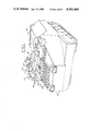
FIG. 1 is a perspective of an armored personnel carrier having a turret mounted thereon in accordance with the invention.
FIG. 2 is a top view of the armored personnel carrier of FIG. 1.
FIG. 3 is an elevation of the turret outside the vehicle with operator's cage attached.
FIG. 4 is an exploded perspective showing the turret mounting components relative to the rim on the top surface of the vehicle.
FIG. 5 is an elevation of the pivot bolt and nut.
FIG. 6 is a partial perspective from inside the vehicle showing the operator's cage attached to the turret which is in the pivoted position.
FIG. 7 is a top perspective into the vehicle showing the operator's cage when the turret is rotated to the position of FIG. 9.
FIG. 8 is a similar view when the turret is pivoted to the position of FIG. 11.
FIG. 9 is a top elevation showing the turret rotated so that the weapons face the rear of the vehicle.
FIG. 10 is a partial perspective of the turret body and exhaust plenum hatch showing a pry bar positioned therebetween to pivot the turret.
FIG. 11 is a top elevation of the vehicle showing the turret pivoted outboard to allow opening of the exhaust plenum hatch.
FIG. 12 is a partial perspective showing the turret pivoted as in FIG. 11.
DESCRIPTION OF PREFERRED EMBODIMENTS
An armored personnel carrier vehicle 10 with a turret 12 mounted in operative position thereon is shown in FIG. 1. The vehicle includes a body 13 having a top surface 16 with an engine exhaust plenum hatch 18 hinged thereon and elevated above top surface 16. As is apparent, the turret 12 includes a portion 12a as well as other similar portions which overhang or overly a portion of the hatch 18 during normal mounting and operation on the vehicle and prevent opening of the hatch. The vehicle also includes an engine intake plenum hatch 20 in front of the turret 12 and with which the turret 12 does not interfere.
The turret carries a pair of weapons 22 and 24, a grenade launcher 26 and observation dome 27 including a plurality of windows 28. As shown better in FIG. 3, the turret 12 also carries an operator's cage or basket 30 which is attached thereto, as will be more fully explained herebelow, for rotation therewith during usual operation and during pivoting of the turret.
The turret has an armor body 14 which terminates on the bottom in a floor 34 with an opening 36 therein, FIG. 4. An annular outer race 40 is attached to the turret floor 34 as by a plurality of threaded bolts 42 and lock washers 44. The outer race 40 cooperates with inner race 46 and bearing cage 48 and balls 50 therebetween. Inner race 46 includes an annular ring gear 52 and is attached to upper flange 54 of an annular riser member 56 which functions as turret support means, such as by a plurality of bolts 58 and lock washers 60. The bottom flange 62 of the riser or turret support member 56 is attached by bolts 64 lock washers 63 and nuts 66 to the rim 13a of the vehicle body 13 with an annular spacer member 70 therebetween around a circular opening C in the vehicle body 13. Annular spacer member 70 is separately affixed to the rim 13a by bolts 65, lock washers 67 and nuts 69, the ends of the bolts 65 being recessed below the top surface of the spacer member 70.
The turret body 14 is thus independently rotatably mounted in an operative position relative to a vertical rotational axis through circular opening C in the vehicle body by means of outer race 40, inner race 46 and balls 50 between the turret body and the riser or turret support member 56 as shown in FIG. 4. A motor 77 is supported in the turret body 14 and includes a pinion 79 in mesh with the ring gear 40 to rotate the turret body 32. The turret is also releasably mounted on the vehicle body by nuts 66 and bolts 64 used to interconnect the riser member 56 in the operative position on the spacer member 70 and vehicle rim 13a. All but one of these bolts 64 are standard 3/4 inch diameter threaded bolts with complementary nuts. However, one set of the nuts and bolts differs from the others in that the bolt 64' is provided with a cylindrical shoulder 64a' along a major portion of its length, as shown in FIG. 5. The bolt 64', lockwasher 63' and companion nut 66' are located at the rear center of the riser member 56 and turret 12 as shown in FIGS. 12 and 4.
By releasing all the bolts 64 and nuts 66 while leaving bolt 64' and its corresponding nut 66' intact but slightly loosened, the turret can be released from its operative position on the vehicle body and placed in an eccentric pivotal mounting relationship thereon so that the turret can be swung or pivoted eccentrically (relative to the vertical axis through opening C) as shown by the arrow in FIG. 12 about the bolt 64' which acts as a pivot means therefor having a pivot axis substantially parallel to the rotational axis of the turret. In this way, the access hatch 18 on the vehicle body can be exposed for opening for maintenance or other purposes without having to remove the turret from the vehicle. The turret 12 can be simply swung back in the opposite direction overlying the access hatch and releasably attached to the riser member 50 following maintenance, as will be explained herebelow. It is apparent that the horizontal plane of rotation of the turret is spaced above and substantially parallel to its horizontal plane of pivoting.
As shown in FIG. 6, an operator's cage 30 is carried on the turret 12 and in particular is bolted to the floor 34 by means of flanges 80 extending from support tubes 82, 84 and seat support tube 86. The support tubes 82, 84, 86 are attached as by welding to a floor portion 90 for example of perforated metal plate. The seat 91 is vertically adjustable and is described in co-pending application entitled Adjustable Height Seat Apparatus For Combat Vehicle, Ser. No. 533,474, of common inventor and assignee herewith.
As is apparent from FIGS. 6, 7 and 8, the cage floor 90 is in the form of a truncated circle having circular arc portion 90a and truncated straight portions 90b, 90c. The support tubes 82, 84, 86 are attached such as by welding around the periphery of the circular arc portion 90a leaving the truncated portions 90b, 90c unobstructed for purposes to be explained herebelow.
The cage floor 90 also carries a container 100 for receiving spent cartridges form one of the weapons 22 or 24 via a flexible hose or chute 102. And, a slip ring 104 is releasably mounted on the bottom of the cage floor 90 by bolts for providing electrical connection for electrical turret controls 108 on the cage.
In FIG. 6, the turret body 14 is shown pivoted or swung away from its releasable operative position on rim 13a and spacer member 70. For example, bolts 65 and nuts 69 attaching the spacer member to the rim are shown along with bolt 64' and nut 66' which provide the pivot means for the turret body. It is apparent that the riser or turret support member 56 has been pivoted relative to the spacer member.
As seen best in FIG. 12, a pulling eyelet 110 is attached to the riser member 50 and is adapted to receive a hook, chain, rope or the like so that the turret 12 can be pivoted or swung out of the way about bolt 64' simply by pulling thereon with light equipment such as a winch or pulley. Typically, the turret will be initially pivoted by use of a pry bar to move it out of the way to allow opening of the exhaust plenum hatch 18 and then the turret will be pulled back to its original operative position by a rope attached to eyelet 110.
Typically, the turret 12 is first rotated so that the weapons 22 and 24 face rearwardly with a turret portion 12a' overhanging the exhaust plenum hatch 18, FIG. 9. Then, the bolts 64 and nuts 66 are removed to release the turret from the releasable fixed mounting on the vehicle with only slight loosening of the pivot bolt 64' and associated nut 66' however. The slip ring 104 is also disconnected by removing four bolts that hold it to the cage floor 90. Then, a pry bar 93 or the like is positioned between the turret body 14 and the exhaust hatch 18, FIG. 10, and the turret is pivoted clockwise to the outboard position illustrated in FIGS. 11 and 12. The exhaust hatch 18 can then be swung open about hinges 18a.
Once the maintenance or other work inside the engine compartment or vehicle is completed, the turret is pivoted back to its original position, e.g., by pulling a rope or chain engaged to the eyelet 110 in the opposite direction (counterclockwise), and bolts 64 and nuts 66 reconnected to again mount the turret on the spacer member 70 and rim 13a of the vehicle. Maintenance of the vehicle under field conditions is thus significantly facilitated.
FIGS. 7 and 8 illustrate the different positions of the operator's cage 30, in particular cage floor 90, during the turret pivoting procedure. For example, FIG. 7 shows the position of the cage floor 90 when the turret is rotated so that the weapons 22, 24 face rearwardly (FIG. 9). It is apparent that the truncated portions 90b, 90c of the cage floor are spaced from outboard vertical wall 13b of the vehicle body with the support tubes 82, 84, 86 of the cage remote from the outboard wall 13b toward the interior of the vehicle. When the turret is eccentrically pivoted clockwise about bolt 64' located at the top of FIG. 7, the cage will move eccentrically to the position shown in FIG. 8 and also FIG. 6 wherein the truncated portion 90b is parallel with the outboard body wall 13b and truncated portion 90c spaced from bracket 120 on the wall 13b. By using an operator's cage configured in the above-described manner, the amount of turret pivoting (approximately 25°) can be accommodated.
While certain specific and preferred embodiments of the invention have been described in detail hereinabove, those skilled in the art will recognize that various modifications and changes can be made therein within the scope of the appended claims which are intended to include equivalents of such embodiments.