US4411495A - Refractive index switchable display cell - Google Patents
Refractive index switchable display cell Download PDFInfo
- Publication number
- US4411495A US4411495A US06/254,509 US25450981A US4411495A US 4411495 A US4411495 A US 4411495A US 25450981 A US25450981 A US 25450981A US 4411495 A US4411495 A US 4411495A
- Authority
- US
- United States
- Prior art keywords
- refraction
- index
- display
- optically
- optically nonabsorbing
- Prior art date
- Legal status (The legal status is an assumption and is not a legal conclusion. Google has not performed a legal analysis and makes no representation as to the accuracy of the status listed.)
- Expired - Lifetime
Links
Images

Classifications
-
- G—PHYSICS
- G02—OPTICS
- G02F—OPTICAL DEVICES OR ARRANGEMENTS FOR THE CONTROL OF LIGHT BY MODIFICATION OF THE OPTICAL PROPERTIES OF THE MEDIA OF THE ELEMENTS INVOLVED THEREIN; NON-LINEAR OPTICS; FREQUENCY-CHANGING OF LIGHT; OPTICAL LOGIC ELEMENTS; OPTICAL ANALOGUE/DIGITAL CONVERTERS
- G02F1/00—Devices or arrangements for the control of the intensity, colour, phase, polarisation or direction of light arriving from an independent light source, e.g. switching, gating or modulating; Non-linear optics
- G02F1/01—Devices or arrangements for the control of the intensity, colour, phase, polarisation or direction of light arriving from an independent light source, e.g. switching, gating or modulating; Non-linear optics for the control of the intensity, phase, polarisation or colour
- G02F1/19—Devices or arrangements for the control of the intensity, colour, phase, polarisation or direction of light arriving from an independent light source, e.g. switching, gating or modulating; Non-linear optics for the control of the intensity, phase, polarisation or colour based on variable-reflection or variable-refraction elements not provided for in groups G02F1/015 - G02F1/169
- G02F1/195—Devices or arrangements for the control of the intensity, colour, phase, polarisation or direction of light arriving from an independent light source, e.g. switching, gating or modulating; Non-linear optics for the control of the intensity, phase, polarisation or colour based on variable-reflection or variable-refraction elements not provided for in groups G02F1/015 - G02F1/169 by using frustrated reflection
-
- G—PHYSICS
- G02—OPTICS
- G02F—OPTICAL DEVICES OR ARRANGEMENTS FOR THE CONTROL OF LIGHT BY MODIFICATION OF THE OPTICAL PROPERTIES OF THE MEDIA OF THE ELEMENTS INVOLVED THEREIN; NON-LINEAR OPTICS; FREQUENCY-CHANGING OF LIGHT; OPTICAL LOGIC ELEMENTS; OPTICAL ANALOGUE/DIGITAL CONVERTERS
- G02F1/00—Devices or arrangements for the control of the intensity, colour, phase, polarisation or direction of light arriving from an independent light source, e.g. switching, gating or modulating; Non-linear optics
- G02F1/01—Devices or arrangements for the control of the intensity, colour, phase, polarisation or direction of light arriving from an independent light source, e.g. switching, gating or modulating; Non-linear optics for the control of the intensity, phase, polarisation or colour
- G02F1/13—Devices or arrangements for the control of the intensity, colour, phase, polarisation or direction of light arriving from an independent light source, e.g. switching, gating or modulating; Non-linear optics for the control of the intensity, phase, polarisation or colour based on liquid crystals, e.g. single liquid crystal display cells
- G02F1/133—Constructional arrangements; Operation of liquid crystal cells; Circuit arrangements
- G02F1/1333—Constructional arrangements; Manufacturing methods
- G02F1/1334—Constructional arrangements; Manufacturing methods based on polymer dispersed liquid crystals, e.g. microencapsulated liquid crystals
-
- G—PHYSICS
- G02—OPTICS
- G02F—OPTICAL DEVICES OR ARRANGEMENTS FOR THE CONTROL OF LIGHT BY MODIFICATION OF THE OPTICAL PROPERTIES OF THE MEDIA OF THE ELEMENTS INVOLVED THEREIN; NON-LINEAR OPTICS; FREQUENCY-CHANGING OF LIGHT; OPTICAL LOGIC ELEMENTS; OPTICAL ANALOGUE/DIGITAL CONVERTERS
- G02F1/00—Devices or arrangements for the control of the intensity, colour, phase, polarisation or direction of light arriving from an independent light source, e.g. switching, gating or modulating; Non-linear optics
- G02F1/01—Devices or arrangements for the control of the intensity, colour, phase, polarisation or direction of light arriving from an independent light source, e.g. switching, gating or modulating; Non-linear optics for the control of the intensity, phase, polarisation or colour
- G02F1/17—Devices or arrangements for the control of the intensity, colour, phase, polarisation or direction of light arriving from an independent light source, e.g. switching, gating or modulating; Non-linear optics for the control of the intensity, phase, polarisation or colour based on variable-absorption elements not provided for in groups G02F1/015 - G02F1/169
- G02F1/172—Devices or arrangements for the control of the intensity, colour, phase, polarisation or direction of light arriving from an independent light source, e.g. switching, gating or modulating; Non-linear optics for the control of the intensity, phase, polarisation or colour based on variable-absorption elements not provided for in groups G02F1/015 - G02F1/169 based on a suspension of orientable dipolar particles, e.g. suspended particles displays
Definitions
- the present invention pertains to the field of passive displays.
- Electrophoretic displays are different from other passive displays, e.g. liquid crystal displays and electrochromic displays, because the electrophoretic display operation depends on a macroscopic motion of solid particles rather than a local change in the medium.
- electrophoretic displays have several advantages: stability should be good because no chemical reactions are involved and a wider choice of materials should be possible because the effect does not depend on the intrinsic properties of the particular material used.
- electrophoretic displays have several disadvantages: They are not very stable because pigments, dyes and charging agents limit the display lifetime and high voltages are required to achieve fast response times. Thus it would be desirable to develop a new display technology that does not suffer from the disadvantages of the electrophoretic display.
- a display cell having at least two states of different opacity comprises a first material having a first index of refraction, a second material dispersed within the first material and having a second index of refraction, the differencebetween the first and the second indices of refraction being variable over a range of values, and means for varying the difference in index of refraction over a portion of the range.
- the display is substantially transparent; otherwise it is opaque or substantially less transparent.
- a liquid crystal material is imbibed into a thin porous layer, which layer is disposed between transparent electrodes.
- a voltage source whose value is variable is applied across said electrodes to vary the index of refraction of the liquid crystal from a value which substantially equals the value of the porous material to values which differ.
- FIG. 1 shows, in pictorial form, an embodiment of the present invention utilizing a liquid crystal material
- FIG. 2 illustrates, in pictorial form, the physical mechanism according to which the present invention operates
- FIG. 3 shows, in pictorial form, an embodiment of the present invention utilizing an anisotropic suspension
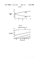
- FIG. 4 shows, in graphical form, the refractive index of an anisotropic suspension
- FIG. 5 shows, in graphical form, the transmittance of a porous solid matrix induced by variations in the refractive index of an anisotropic suspension medium disposed within the pores.
- the present invention pertains to a passive display.
- a first material having a first index of refraction has a second material dispersed therein.
- the difference in index of refraction between the first and the second material is variable over a range of values.
- the display includes means for varying the difference in index of refraction over at least a portion of its range.
- the display has at least two states of different opacity, which different opacities depend upon the relative values of the indices of refraction of the two materials.
- FIG. 1 shows, in pictorial form, an embodiment of the present invention.
- the filter was imbibed with liquid crystal material 85 in the nematic mesophase, e.g. E. Merck No. 1003 obtained from E. M. Laboratories, Inc., an associate of E. Merck, Darmstadt, Germany, 500 Executive Boulevard, Elmsford, N.Y., 10523.
- Voltage source 83 was applied across transparent electrodes 80 and 81 to provide an electric field through layer 82. Varying the amplitude of the electric field across layer 82 by varying the value of the voltage from voltage source 83 changed the opacity of layer 82.
- FIG. 2 shows, in pictorial form, the physical mechanism according to which the display operates.
- Layer 1 is a nonabsorbing layer comprising solid material 10.
- Layer 1 is porous on the scale of optical wavelengths. Because of this scale of porosity, layer 1 destroys the spatial coherence of incident radiation and appears white, like e.g. frosted glass. If layer 1 is sufficiently thick, e.g. at least 10 ⁇ m, the porous solid acts as a totally diffusely reflecting surface.
- Layer 2 in FIG. 2 comprises the same porous solid material as that of layer 1 imbibed with liquid 11 whose index of refraction matches that of material 10. Because of the index matching, layer 2 is now transparent.
- FIG. 3 shows an embodiment constructed according to the present invention.
- Optically nonabsorbing porous layer 5 comprising solid material 6 is sandwiched between transparent conducting plates 30 and 31, e.g. SnO 2 coated glass.
- Layer 5 is imbibed with liquid 15.
- the index of refraction of liquid 15 can be varied between different values by the application of different values of an electric field.
- the different values of electric field are produced by varying the voltage applied to conducting plates 30 and 31 by voltage source 32.
- the display has varying opacity depending upon the value of the applied electric field. When the index of refraction of solid material 6 and liquid 15 are substantially equal, the display is transparent.
- Cell 3 in FIG. 3 shows the effect the cell has on incident radiation when the index of refraction of liquid 15 substantially matches that of solid material 6.
- liquid 15 comprises an anisotropic suspension.
- the composition of the suspension is adjusted so that in the random state its refractive index matches that of the solid. This insures transparency at all viewing angles since the random orientation of particles forms an effectively isotropic medium.
- Colored displays can be fabricated if absorber 27 behind electrode 31 reflects some light back through the display. By applying a d.c. field between the two transparent conductors the particles in the suspension are oriented parallel to the field and the refractive index of the suspension decreases by approximately 2 percent to produce an incoherent diffuse reflection and thus, a frosted appearance (e.g. white under ordinary lighting) of the display. Since the random orientation of the particles produces an optically isotropic medium, the angle of view problem associated with liquid crystal displays is not present.
- Both the particles and the liquid medium of the suspension are substantially nonabsorbing to radiation in the range of wavelength over which the display is to operate, for example, the visible portion of the light spectrum.
- the exact size of the particles is not critical but their characteristic length must be much less than that of the wavelength of the radiation, for example, for visible light the characteristic length should be less than or substantially equal to 100 ⁇
- the shape of the particles is a fundamental parameter, the preferred shape being needle-like, e.g. prolate ellipsoids. To insure maximum filling of the liquid without significant interparticle contact, the particles should occupy less than or substantially equal to 10 percent of the liquid suspension volume.
- both the static and optical dielectric constants of the particles and the liquid medium should differ as much as possible.
- the suspension is a composite medium to which Maxwell Garnett's theory of dielectric constants, found in an article entitled "Colours in Metal Glasses and in Metallic Films", Phil. Trans. Rov. Soc., London, Vol. 203, pp. 385-420, 1904 by J. C. Maxwell Garnett, can be rigorously applied.
- Maxwell Garnett's theory gives the expression for the dielectric constant ⁇ > of the anisotropic suspension:
- f is the filling factor, i.e. the ratio of particle volume to liquid medium volume (approximately 10 percent in this case)
- ⁇ s and ⁇ L are the optical dielectric constants of the particles and the liquid medium respectively
- g is a factor which depends on the shape of the particles and their orientation with respect to the electric field.
- FIG. 4 shows the results of Maxwell Garnett theory calculations of the refractive indices of the TiO 2 -H 2 O anisotropic suspension as a function of the axes ratio c/a. It is clear from the figure that refractive index changes of 0.03 or approximately 2 percent can be obtained with a relatively low axes ratio, i.e., 4, which ratio is well within practical limits for material fabrication.
- FIG. 5 shows the unscattered transmittance change induced by refractive index variations as a function of wavelength.
- the measurements were performed using a Cary 14 spectrophotometer (Varian/Instrument Group, 611 Hansen Way, Palo Alto, Calif. 94303) in the normal transmission mode.
- the samples consisted of a 130 ⁇ m thick MILLIPORE type MF porous filter, described hereinabove with respect to the embodiment shown in FIG. 1, immersed in liquids of varying known refractive indices.
- the appearance of the samples in the index matched state is like a clear piece of glass. In the nonmatched state the sample appears white with normal lighting, having an opacity which increases with increasing mismatch.
- the most general aspect of the present invention is a dispersion of two immiscible phases of materials and means for varying the difference in the indices of refraction between the two phases.
- modulating the index of refraction of a solid by 1-2 percent presently requires single crystals of materials, e.g., Lithium Niobate and very high electric fields, e.g. on the order of 1 Volt/ ⁇ m.
- the means for reorienting or altering the index of refraction as discussed hereinabove need not be restricted to one or either of the two materials or to the application of electric fields.
- the application of pressure, heat, magnetic fields or a photon flux may be used in certain embodiments to vary the relative index of refraction.
- the application of magnetic fields would be suitable for a liquid crystal embodiment and the application of heat would be suitable for causing a phase transition in a material such as napthalene dispersed within a solid.
Abstract
Description
<ε>=[ε.sub.s g+ε.sub.L (f.sup.-1 -1)]/[g+(f.sup.-1 -1)] (1)
g.sub.R =2/3g.sub.O +1/3[1+L.sub.c (ε.sub.S /ε.sub.L -1)].sup.-1 (2)
g.sub.O =[1+L.sub.a (ε.sub.S /ε.sub.L -1)].sup.-1 (3)
Claims (10)
Priority Applications (1)
| Application Number | Priority Date | Filing Date | Title |
|---|---|---|---|
| US06/254,509 US4411495A (en) | 1981-04-15 | 1981-04-15 | Refractive index switchable display cell |
Applications Claiming Priority (1)
| Application Number | Priority Date | Filing Date | Title |
|---|---|---|---|
| US06/254,509 US4411495A (en) | 1981-04-15 | 1981-04-15 | Refractive index switchable display cell |
Publications (1)
| Publication Number | Publication Date |
|---|---|
| US4411495A true US4411495A (en) | 1983-10-25 |
Family
ID=22964557
Family Applications (1)
| Application Number | Title | Priority Date | Filing Date |
|---|---|---|---|
| US06/254,509 Expired - Lifetime US4411495A (en) | 1981-04-15 | 1981-04-15 | Refractive index switchable display cell |
Country Status (1)
| Country | Link |
|---|---|
| US (1) | US4411495A (en) |
Cited By (45)
| Publication number | Priority date | Publication date | Assignee | Title |
|---|---|---|---|---|
| US4579423A (en) * | 1981-09-16 | 1986-04-01 | Manchester R & D Partnership | Encapsulated liquid crystal and method |
| US4591233A (en) * | 1983-03-21 | 1986-05-27 | Manchester R & D Partnership | Enhanced scattering in voltage sensitive encapsulated liquid crystal with spaced apart absorber |
| US4596445A (en) * | 1983-03-30 | 1986-06-24 | Manchester R & D Partnership | Colored encapsulated liquid crystal apparatus using enhanced scattering |
| US4606611A (en) * | 1981-09-16 | 1986-08-19 | Manchester R & D Partnership | Enhanced scattering in voltage sensitive encapsulated liquid crystal |
| US4616903A (en) * | 1981-09-16 | 1986-10-14 | Manchester R & D Partnership | Encapsulated liquid crystal and method |
| US4662720A (en) * | 1983-03-30 | 1987-05-05 | Manchester R & D Partnership | Colored encapsulated liquid crystal devices using imbibition of colored dyes and scanned multicolor displays |
| US4707080A (en) * | 1981-09-16 | 1987-11-17 | Manchester R & D Partnership | Encapsulated liquid crystal material, apparatus and method |
| US4720172A (en) * | 1985-11-05 | 1988-01-19 | Itt Defense Communications, A Division Of Itt Corporation | Liquid crystal optical switching device |
| US4732456A (en) * | 1984-08-28 | 1988-03-22 | Taliq Corporation | Scattering display for contrast enhancement including target |
| US4737019A (en) * | 1985-11-05 | 1988-04-12 | Itt Defense Communications, A Division Of Itt Corporation | Liquid crystal optical switching device having minimized internal light path |
| US4810063A (en) * | 1981-09-16 | 1989-03-07 | Manchester R & D Partnership | Enhanced scattering voltage sensitive encapsulated liquid crystal with light directing and interference layer features |
| US4815826A (en) * | 1983-03-30 | 1989-03-28 | Manchester R & D Partnership | Colored encapsulated liquid crystal apparatus using enhanced scattering, fluorescent dye and dielectric thin films |
| US4818070A (en) * | 1987-01-22 | 1989-04-04 | Asahi Glass Company Ltd. | Liquid crystal optical device using U.V.-cured polymer dispersions and process for its production |
| US4832458A (en) * | 1984-08-28 | 1989-05-23 | Talig Corporation | Display for contrast enhancement |
| US4838660A (en) * | 1983-03-30 | 1989-06-13 | Manchester R & D Partnership | Colored encapsulated liquid crystal apparatus using enhanced scattering |
| US4850678A (en) * | 1983-03-30 | 1989-07-25 | Manchester R & D Partnership | Colored encapsulated liquid crystal apparatus using enhanced scattering |
| US4856876A (en) * | 1983-03-30 | 1989-08-15 | Manchester R & D Partnership | Fluorescent colored encapsulated liquid crystal apparatus using enhanced scattering |
| EP0343903A2 (en) * | 1988-05-23 | 1989-11-29 | Imperial Chemical Industries Plc | Liquid crystal devices |
| US4884873A (en) * | 1981-09-16 | 1989-12-05 | Manchester R & D Partnership | Encapsulated liquid crystal material, apparatus and method having interconnected capsules |
| US4890902A (en) * | 1985-09-17 | 1990-01-02 | Kent State University | Liquid crystal light modulating materials with selectable viewing angles |
| US4925708A (en) * | 1987-12-16 | 1990-05-15 | Imperial Chemical Industries Plc | Process for producing liquid crystal devices |
| US5052784A (en) * | 1986-06-23 | 1991-10-01 | Manchester R&D Partnership | Fluorescent colored encapsulated liquid crystal apparatus using enhanced scattering |
| US5082351A (en) * | 1981-09-16 | 1992-01-21 | Manchester R & D Partnership | Encapsulated liquid crystal material, apparatus and method |
| US5089904A (en) * | 1981-09-16 | 1992-02-18 | Fergason James L | Encapsulated liquid crystal material, apparatus and method |
| EP0475117A2 (en) * | 1990-08-17 | 1992-03-18 | Dainippon Ink And Chemicals, Inc. | Liquid crystal device and process for producing the same |
| US5103326A (en) * | 1983-03-30 | 1992-04-07 | Manchester R&D Partnership | Fluorescent colored encapsulated liquid crystal apparatus using enhanced scattering |
| US5299037A (en) * | 1985-08-07 | 1994-03-29 | Canon Kabushiki Kaisha | Diffraction grating type liquid crystal display device in viewfinder |
| US5473448A (en) * | 1992-03-18 | 1995-12-05 | Canon Kabushiki Kaisha | Display device having a mesomorphic diffraction grating layer adjacent a polymer dispersed layer |
| US5475515A (en) * | 1991-05-01 | 1995-12-12 | Canon Kabushiki Kaisha | Liquid crystal device having a stretched porous polymer film impregnated with a low molecular weight mesomorphic compound |
| US5593615A (en) * | 1994-04-29 | 1997-01-14 | Minnesota Mining And Manufacturing Company | Light modulating device having a matrix prepared from acid reactants |
| US5641426A (en) * | 1994-04-29 | 1997-06-24 | Minnesota Mining And Manufacturing Company | Light modulating device having a vinyl ether-based matrix |
| WO1997046908A1 (en) * | 1996-06-05 | 1997-12-11 | Forschungszentrum Jülich GmbH | Interference filter based on porous silicon |
| US5812227A (en) * | 1992-04-02 | 1998-09-22 | Canon Kabushiki Kaisha | Liquid crystal device, display apparatus using same and display method using same |
| US5867238A (en) * | 1991-01-11 | 1999-02-02 | Minnesota Mining And Manufacturing Company | Polymer-dispersed liquid crystal device having an ultraviolet-polymerizable matrix and a variable optical transmission and a method for preparing same |
| US6046837A (en) * | 1997-12-08 | 2000-04-04 | Fuji Photo Film Co., Ltd. | Optical modulator |
| US6122021A (en) * | 1988-10-04 | 2000-09-19 | Asahi Glass Company, Ltd. | Liquid crystal display element and a projection type liquid crystal display apparatus |
| US20030193471A1 (en) * | 1990-03-23 | 2003-10-16 | Mitsuaki Oshima | Data processing apparatus |
| US20040136048A1 (en) * | 1995-07-20 | 2004-07-15 | E Ink Corporation | Dielectrophoretic displays |
| US7463398B2 (en) | 2002-02-19 | 2008-12-09 | Liquivista B.V. | Display device |
| US7583251B2 (en) | 1995-07-20 | 2009-09-01 | E Ink Corporation | Dielectrophoretic displays |
| US7999787B2 (en) | 1995-07-20 | 2011-08-16 | E Ink Corporation | Methods for driving electrophoretic displays using dielectrophoretic forces |
| US9664978B2 (en) | 2002-10-16 | 2017-05-30 | E Ink Corporation | Electrophoretic displays |
| US20180149916A1 (en) * | 2016-11-30 | 2018-05-31 | Lg Display Co., Ltd. | Polarizer, method for fabricating the same, and display device having the same |
| WO2019113596A1 (en) * | 2017-12-08 | 2019-06-13 | The Trustees Of Columbia University In The City Of New York | Scalable method of fabricating structured polymers for passive daytime radiative cooling and other applications |
| US11250794B2 (en) | 2004-07-27 | 2022-02-15 | E Ink Corporation | Methods for driving electrophoretic displays using dielectrophoretic forces |
Citations (13)
| Publication number | Priority date | Publication date | Assignee | Title |
|---|---|---|---|---|
| US2953819A (en) * | 1959-05-18 | 1960-09-27 | Celon Company | Method of casting plastic articles having integral sheen |
| US3030852A (en) * | 1960-10-07 | 1962-04-24 | Bell Telephone Labor Inc | Optical device for use in controlling light transmission |
| US3390933A (en) * | 1964-11-25 | 1968-07-02 | American Optical Corp | Variable density light transmitting device |
| US3458249A (en) * | 1964-03-16 | 1969-07-29 | California Inst Res Found | Light rejection band filter |
| US3832033A (en) * | 1971-12-17 | 1974-08-27 | Hitachi Ltd | Regular ferroelectrics-liquid crystal composite optical element |
| US3918794A (en) * | 1974-11-29 | 1975-11-11 | Us Navy | Liquid crystal optical switch coupler |
| US3951520A (en) * | 1974-10-16 | 1976-04-20 | E. I. Du Pont De Nemours And Company | Color imaging using the Christiansen effect |
| US3961181A (en) * | 1975-02-18 | 1976-06-01 | Golden Eddie R | Eye-shading means for automotive vehicle operators |
| US4021846A (en) * | 1972-09-25 | 1977-05-03 | The United States Of America As Represented By The Secretary Of The Navy | Liquid crystal stereoscopic viewer |
| US4046456A (en) * | 1976-04-22 | 1977-09-06 | Honeywell Inc. | Electro-optic cell with transverse electric field |
| US4066335A (en) * | 1976-01-19 | 1978-01-03 | Xerox Corporation | Variable density lens |
| US4097128A (en) * | 1975-04-24 | 1978-06-27 | Tokyo Shibaura Electric Co., Ltd. | Liquid crystal color display devices |
| US4214819A (en) * | 1977-10-29 | 1980-07-29 | Merck Patent Gesellschaft Mit Beschrankter Haftung | Electro-optical modulator |
-
1981
- 1981-04-15 US US06/254,509 patent/US4411495A/en not_active Expired - Lifetime
Patent Citations (13)
| Publication number | Priority date | Publication date | Assignee | Title |
|---|---|---|---|---|
| US2953819A (en) * | 1959-05-18 | 1960-09-27 | Celon Company | Method of casting plastic articles having integral sheen |
| US3030852A (en) * | 1960-10-07 | 1962-04-24 | Bell Telephone Labor Inc | Optical device for use in controlling light transmission |
| US3458249A (en) * | 1964-03-16 | 1969-07-29 | California Inst Res Found | Light rejection band filter |
| US3390933A (en) * | 1964-11-25 | 1968-07-02 | American Optical Corp | Variable density light transmitting device |
| US3832033A (en) * | 1971-12-17 | 1974-08-27 | Hitachi Ltd | Regular ferroelectrics-liquid crystal composite optical element |
| US4021846A (en) * | 1972-09-25 | 1977-05-03 | The United States Of America As Represented By The Secretary Of The Navy | Liquid crystal stereoscopic viewer |
| US3951520A (en) * | 1974-10-16 | 1976-04-20 | E. I. Du Pont De Nemours And Company | Color imaging using the Christiansen effect |
| US3918794A (en) * | 1974-11-29 | 1975-11-11 | Us Navy | Liquid crystal optical switch coupler |
| US3961181A (en) * | 1975-02-18 | 1976-06-01 | Golden Eddie R | Eye-shading means for automotive vehicle operators |
| US4097128A (en) * | 1975-04-24 | 1978-06-27 | Tokyo Shibaura Electric Co., Ltd. | Liquid crystal color display devices |
| US4066335A (en) * | 1976-01-19 | 1978-01-03 | Xerox Corporation | Variable density lens |
| US4046456A (en) * | 1976-04-22 | 1977-09-06 | Honeywell Inc. | Electro-optic cell with transverse electric field |
| US4214819A (en) * | 1977-10-29 | 1980-07-29 | Merck Patent Gesellschaft Mit Beschrankter Haftung | Electro-optical modulator |
Non-Patent Citations (4)
| Title |
|---|
| Birks et al., Editor, Progress in Dielectrics, vol. 6, Academic Press Inc. New York 1965. * |
| Garnett, "Colours in Metal Glasses and in Metallic Film" Phil. Trans. Roy, Soc., London, vol. 203, pp. 385-420, 1904. * |
| Marks, "Electro-Optical Characteristics", Appl. Optics, vol. 8, No. 7, Jul. 1969, pp. 1397-11412. * |
| Matsumoto et al., II, "New Multicolor Liquid-Crystal Display" _Toshiba Review No. 108, Mar.-Apr. 1977, pp. 32-35. * |
Cited By (61)
| Publication number | Priority date | Publication date | Assignee | Title |
|---|---|---|---|---|
| US4810063A (en) * | 1981-09-16 | 1989-03-07 | Manchester R & D Partnership | Enhanced scattering voltage sensitive encapsulated liquid crystal with light directing and interference layer features |
| US4884873A (en) * | 1981-09-16 | 1989-12-05 | Manchester R & D Partnership | Encapsulated liquid crystal material, apparatus and method having interconnected capsules |
| US4606611A (en) * | 1981-09-16 | 1986-08-19 | Manchester R & D Partnership | Enhanced scattering in voltage sensitive encapsulated liquid crystal |
| US4616903A (en) * | 1981-09-16 | 1986-10-14 | Manchester R & D Partnership | Encapsulated liquid crystal and method |
| US5082351A (en) * | 1981-09-16 | 1992-01-21 | Manchester R & D Partnership | Encapsulated liquid crystal material, apparatus and method |
| US4707080A (en) * | 1981-09-16 | 1987-11-17 | Manchester R & D Partnership | Encapsulated liquid crystal material, apparatus and method |
| US4579423A (en) * | 1981-09-16 | 1986-04-01 | Manchester R & D Partnership | Encapsulated liquid crystal and method |
| US5089904A (en) * | 1981-09-16 | 1992-02-18 | Fergason James L | Encapsulated liquid crystal material, apparatus and method |
| US4591233A (en) * | 1983-03-21 | 1986-05-27 | Manchester R & D Partnership | Enhanced scattering in voltage sensitive encapsulated liquid crystal with spaced apart absorber |
| US4662720A (en) * | 1983-03-30 | 1987-05-05 | Manchester R & D Partnership | Colored encapsulated liquid crystal devices using imbibition of colored dyes and scanned multicolor displays |
| US4815826A (en) * | 1983-03-30 | 1989-03-28 | Manchester R & D Partnership | Colored encapsulated liquid crystal apparatus using enhanced scattering, fluorescent dye and dielectric thin films |
| US5103326A (en) * | 1983-03-30 | 1992-04-07 | Manchester R&D Partnership | Fluorescent colored encapsulated liquid crystal apparatus using enhanced scattering |
| US4838660A (en) * | 1983-03-30 | 1989-06-13 | Manchester R & D Partnership | Colored encapsulated liquid crystal apparatus using enhanced scattering |
| US4850678A (en) * | 1983-03-30 | 1989-07-25 | Manchester R & D Partnership | Colored encapsulated liquid crystal apparatus using enhanced scattering |
| US4856876A (en) * | 1983-03-30 | 1989-08-15 | Manchester R & D Partnership | Fluorescent colored encapsulated liquid crystal apparatus using enhanced scattering |
| US4596445A (en) * | 1983-03-30 | 1986-06-24 | Manchester R & D Partnership | Colored encapsulated liquid crystal apparatus using enhanced scattering |
| US4832458A (en) * | 1984-08-28 | 1989-05-23 | Talig Corporation | Display for contrast enhancement |
| US4732456A (en) * | 1984-08-28 | 1988-03-22 | Taliq Corporation | Scattering display for contrast enhancement including target |
| US5299037A (en) * | 1985-08-07 | 1994-03-29 | Canon Kabushiki Kaisha | Diffraction grating type liquid crystal display device in viewfinder |
| US4890902A (en) * | 1985-09-17 | 1990-01-02 | Kent State University | Liquid crystal light modulating materials with selectable viewing angles |
| US4737019A (en) * | 1985-11-05 | 1988-04-12 | Itt Defense Communications, A Division Of Itt Corporation | Liquid crystal optical switching device having minimized internal light path |
| US4720172A (en) * | 1985-11-05 | 1988-01-19 | Itt Defense Communications, A Division Of Itt Corporation | Liquid crystal optical switching device |
| US5052784A (en) * | 1986-06-23 | 1991-10-01 | Manchester R&D Partnership | Fluorescent colored encapsulated liquid crystal apparatus using enhanced scattering |
| US4818070A (en) * | 1987-01-22 | 1989-04-04 | Asahi Glass Company Ltd. | Liquid crystal optical device using U.V.-cured polymer dispersions and process for its production |
| US4925708A (en) * | 1987-12-16 | 1990-05-15 | Imperial Chemical Industries Plc | Process for producing liquid crystal devices |
| EP0343903A3 (en) * | 1988-05-23 | 1990-10-17 | Imperial Chemical Industries Plc | Liquid crystal devices |
| EP0343903A2 (en) * | 1988-05-23 | 1989-11-29 | Imperial Chemical Industries Plc | Liquid crystal devices |
| US6122021A (en) * | 1988-10-04 | 2000-09-19 | Asahi Glass Company, Ltd. | Liquid crystal display element and a projection type liquid crystal display apparatus |
| US7120809B2 (en) * | 1990-03-23 | 2006-10-10 | Matsushita Electric Industrial Co., Ltd. | Data processing apparatus |
| US7024572B2 (en) * | 1990-03-23 | 2006-04-04 | Matsushita Electric Industrial Co., Ltd. | Data processing apparatus |
| US20030193468A1 (en) * | 1990-03-23 | 2003-10-16 | Mitsuaki Oshima | Data processing apparatus |
| US20030193471A1 (en) * | 1990-03-23 | 2003-10-16 | Mitsuaki Oshima | Data processing apparatus |
| US5327271A (en) * | 1990-08-17 | 1994-07-05 | Dainippon Ink And Chemical, Inc. | Liquid crystal device employing polymer network on one substrate and alignment layer or polymer network on other substrate |
| EP0475117A3 (en) * | 1990-08-17 | 1992-11-25 | Dainippon Ink And Chemicals, Inc. | Liquid crystal device and process for producing the same |
| EP0475117A2 (en) * | 1990-08-17 | 1992-03-18 | Dainippon Ink And Chemicals, Inc. | Liquid crystal device and process for producing the same |
| US5867238A (en) * | 1991-01-11 | 1999-02-02 | Minnesota Mining And Manufacturing Company | Polymer-dispersed liquid crystal device having an ultraviolet-polymerizable matrix and a variable optical transmission and a method for preparing same |
| US5475515A (en) * | 1991-05-01 | 1995-12-12 | Canon Kabushiki Kaisha | Liquid crystal device having a stretched porous polymer film impregnated with a low molecular weight mesomorphic compound |
| US5473448A (en) * | 1992-03-18 | 1995-12-05 | Canon Kabushiki Kaisha | Display device having a mesomorphic diffraction grating layer adjacent a polymer dispersed layer |
| US5812227A (en) * | 1992-04-02 | 1998-09-22 | Canon Kabushiki Kaisha | Liquid crystal device, display apparatus using same and display method using same |
| US5593615A (en) * | 1994-04-29 | 1997-01-14 | Minnesota Mining And Manufacturing Company | Light modulating device having a matrix prepared from acid reactants |
| US5641426A (en) * | 1994-04-29 | 1997-06-24 | Minnesota Mining And Manufacturing Company | Light modulating device having a vinyl ether-based matrix |
| US7999787B2 (en) | 1995-07-20 | 2011-08-16 | E Ink Corporation | Methods for driving electrophoretic displays using dielectrophoretic forces |
| US7259744B2 (en) * | 1995-07-20 | 2007-08-21 | E Ink Corporation | Dielectrophoretic displays |
| US8305341B2 (en) | 1995-07-20 | 2012-11-06 | E Ink Corporation | Dielectrophoretic displays |
| US7583251B2 (en) | 1995-07-20 | 2009-09-01 | E Ink Corporation | Dielectrophoretic displays |
| US20040136048A1 (en) * | 1995-07-20 | 2004-07-15 | E Ink Corporation | Dielectrophoretic displays |
| WO1997046908A1 (en) * | 1996-06-05 | 1997-12-11 | Forschungszentrum Jülich GmbH | Interference filter based on porous silicon |
| US6046837A (en) * | 1997-12-08 | 2000-04-04 | Fuji Photo Film Co., Ltd. | Optical modulator |
| US8213071B2 (en) | 2002-02-19 | 2012-07-03 | Samsung Lcd Netherlands R & D Center B.V. | Display device |
| US20110116153A1 (en) * | 2002-02-19 | 2011-05-19 | Liquavista B.V. | Display device |
| US7898718B2 (en) | 2002-02-19 | 2011-03-01 | Liquavista B.V. | Display device |
| US7463398B2 (en) | 2002-02-19 | 2008-12-09 | Liquivista B.V. | Display device |
| US9664978B2 (en) | 2002-10-16 | 2017-05-30 | E Ink Corporation | Electrophoretic displays |
| US10331005B2 (en) | 2002-10-16 | 2019-06-25 | E Ink Corporation | Electrophoretic displays |
| US11250794B2 (en) | 2004-07-27 | 2022-02-15 | E Ink Corporation | Methods for driving electrophoretic displays using dielectrophoretic forces |
| US20180149916A1 (en) * | 2016-11-30 | 2018-05-31 | Lg Display Co., Ltd. | Polarizer, method for fabricating the same, and display device having the same |
| US10451917B2 (en) * | 2016-11-30 | 2019-10-22 | Lg Display Co., Ltd. | Polarizer, method for fabricating the same, and display device having the same |
| WO2019113596A1 (en) * | 2017-12-08 | 2019-06-13 | The Trustees Of Columbia University In The City Of New York | Scalable method of fabricating structured polymers for passive daytime radiative cooling and other applications |
| US20210165206A1 (en) * | 2017-12-08 | 2021-06-03 | The Trustees Of Columbia University In The City Of New York | Scalable method of fabricating structured polymers for passive daytime radiative cooling and other applications |
| US11740450B2 (en) | 2017-12-08 | 2023-08-29 | The Trustees Of Columbia University In The City Of New York | Scalable method of fabricating structured polymers for passive daytime radiative cooling and other applications |
| US11940616B2 (en) * | 2017-12-08 | 2024-03-26 | The Trustees Of Columbia University In The City Of New York | Scalable method of fabricating structured polymers for passive daytime radiative cooling and other applications |
Similar Documents
| Publication | Publication Date | Title |
|---|---|---|
| US4411495A (en) | Refractive index switchable display cell | |
| US3694053A (en) | Nematic liquid crystal device | |
| US4436379A (en) | Two-layer liquid crystal display panel | |
| KR900008064B1 (en) | Liquid crystal display | |
| US3703329A (en) | Liquid crystal color display | |
| US3675988A (en) | Liquid crystal electro-optical measurement and display devices | |
| CA1264846A (en) | Double layer display | |
| Nose et al. | Refractive index of nematic liquid crystals in the submillimeter wave region | |
| Bigelow et al. | Poincaré sphere analysis of liquid crystal optics | |
| EP0021336A1 (en) | Optical display devices | |
| KR100381077B1 (en) | Liquid crystal display device and electronic apparatus | |
| US5223959A (en) | Red, blue and green serial encapsulated liquid crystal display and driving method | |
| Kalish et al. | Transformation of mode polarization in gyrotropic plasmonic waveguides | |
| GB1531010A (en) | Thermal method for controlling the optical properties of a liquid crystal and to devices for carrying out said method | |
| JPH08304788A (en) | Polymer dispersion type liquid crystal element | |
| US3741629A (en) | Electronically variable iris or stop mechanisms | |
| US4385805A (en) | Liquid crystal lens display system | |
| US4579422A (en) | Liquid crystal device for continuous rotation of selective polarization of monochromatic light | |
| EP0611456A1 (en) | Twisted ferroelectric liquid crystal modulator | |
| Klosowicz et al. | Optics and electro-optics of polymer-dispersed liquid crystals: physics, technology, and application | |
| Fan et al. | Broadband integrated polarization rotator using three-layer metallic grating structures | |
| Hopmann et al. | Advances in electrochromic device technology through the exploitation of nanophotonic and nanoplasmonic effects | |
| SU694102A3 (en) | Photocell | |
| KR0144680B1 (en) | Liquid crystal light modulation device and apparatus | |
| Beni et al. | Anisotropic suspension display |
Legal Events
| Date | Code | Title | Description |
|---|---|---|---|
| AS | Assignment |
Owner name: BELL TELEPHONE LABORATORIES,INCORPORATED, 600 MOUN Free format text: ASSIGNMENT OF ASSIGNORS INTEREST.;ASSIGNORS:BENI GERARADO;CRAIGHEAD HAROLD G.;HACKWOOD SUSAN;REEL/FRAME:003878/0675 Effective date: 19810409 Owner name: BELL TELEPHONE LABORATORIES, INCORPORATED, A CORP. Free format text: ASSIGNMENT OF ASSIGNORS INTEREST;ASSIGNORS:BENI GERARADO;CRAIGHEAD HAROLD G.;HACKWOOD SUSAN;REEL/FRAME:003878/0675 Effective date: 19810409 |
|
| STCF | Information on status: patent grant |
Free format text: PATENTED CASE |
|
| MAFP | Maintenance fee payment |
Free format text: PAYMENT OF MAINTENANCE FEE, 4TH YEAR, PL 96-517 (ORIGINAL EVENT CODE: M170); ENTITY STATUS OF PATENT OWNER: LARGE ENTITY Year of fee payment: 4 |
|
| FEPP | Fee payment procedure |
Free format text: PAYOR NUMBER ASSIGNED (ORIGINAL EVENT CODE: ASPN); ENTITY STATUS OF PATENT OWNER: LARGE ENTITY |
|
| MAFP | Maintenance fee payment |
Free format text: PAYMENT OF MAINTENANCE FEE, 8TH YEAR, PL 96-517 (ORIGINAL EVENT CODE: M171); ENTITY STATUS OF PATENT OWNER: LARGE ENTITY Year of fee payment: 8 |
|
| MAFP | Maintenance fee payment |
Free format text: PAYMENT OF MAINTENANCE FEE, 12TH YEAR, LARGE ENTITY (ORIGINAL EVENT CODE: M185); ENTITY STATUS OF PATENT OWNER: LARGE ENTITY Year of fee payment: 12 |