US4026111A - Method of removing dissolved non-condensibles from geothermal brines - Google Patents
Method of removing dissolved non-condensibles from geothermal brines Download PDFInfo
- Publication number
- US4026111A US4026111A US05/654,826 US65482676A US4026111A US 4026111 A US4026111 A US 4026111A US 65482676 A US65482676 A US 65482676A US 4026111 A US4026111 A US 4026111A
- Authority
- US
- United States
- Prior art keywords
- steam
- motive steam
- turbine
- brine
- brines
- Prior art date
- Legal status (The legal status is an assumption and is not a legal conclusion. Google has not performed a legal analysis and makes no representation as to the accuracy of the status listed.)
- Expired - Lifetime
Links
- 238000000034 method Methods 0.000 title claims description 10
- 239000007789 gas Substances 0.000 claims abstract description 21
- 239000012267 brine Substances 0.000 claims abstract description 16
- HPALAKNZSZLMCH-UHFFFAOYSA-M sodium;chloride;hydrate Chemical compound O.[Na+].[Cl-] HPALAKNZSZLMCH-UHFFFAOYSA-M 0.000 claims abstract description 16
- 239000007791 liquid phase Substances 0.000 claims description 7
- 239000012808 vapor phase Substances 0.000 claims description 6
- 238000003303 reheating Methods 0.000 abstract 1
- 239000007788 liquid Substances 0.000 description 8
- 238000001816 cooling Methods 0.000 description 6
- XLYOFNOQVPJJNP-UHFFFAOYSA-N water Substances O XLYOFNOQVPJJNP-UHFFFAOYSA-N 0.000 description 6
- FAPWRFPIFSIZLT-UHFFFAOYSA-M Sodium chloride Chemical compound [Na+].[Cl-] FAPWRFPIFSIZLT-UHFFFAOYSA-M 0.000 description 4
- 238000004519 manufacturing process Methods 0.000 description 4
- VEXZGXHMUGYJMC-UHFFFAOYSA-M Chloride anion Chemical compound [Cl-] VEXZGXHMUGYJMC-UHFFFAOYSA-M 0.000 description 3
- 239000012530 fluid Substances 0.000 description 3
- 239000000203 mixture Substances 0.000 description 3
- 239000002244 precipitate Substances 0.000 description 3
- QGZKDVFQNNGYKY-UHFFFAOYSA-N Ammonia Chemical compound N QGZKDVFQNNGYKY-UHFFFAOYSA-N 0.000 description 2
- XKRFYHLGVUSROY-UHFFFAOYSA-N Argon Chemical compound [Ar] XKRFYHLGVUSROY-UHFFFAOYSA-N 0.000 description 2
- IJGRMHOSHXDMSA-UHFFFAOYSA-N Atomic nitrogen Chemical compound N#N IJGRMHOSHXDMSA-UHFFFAOYSA-N 0.000 description 2
- 229910021532 Calcite Inorganic materials 0.000 description 2
- VYPSYNLAJGMNEJ-UHFFFAOYSA-N Silicium dioxide Chemical compound O=[Si]=O VYPSYNLAJGMNEJ-UHFFFAOYSA-N 0.000 description 2
- QAOWNCQODCNURD-UHFFFAOYSA-L Sulfate Chemical compound [O-]S([O-])(=O)=O QAOWNCQODCNURD-UHFFFAOYSA-L 0.000 description 2
- 239000002253 acid Substances 0.000 description 2
- QAOWNCQODCNURD-UHFFFAOYSA-M bisulphate group Chemical group S([O-])(O)(=O)=O QAOWNCQODCNURD-UHFFFAOYSA-M 0.000 description 2
- 230000000694 effects Effects 0.000 description 2
- 230000003628 erosive effect Effects 0.000 description 2
- 229910052500 inorganic mineral Inorganic materials 0.000 description 2
- VNWKTOKETHGBQD-UHFFFAOYSA-N methane Chemical compound C VNWKTOKETHGBQD-UHFFFAOYSA-N 0.000 description 2
- 239000011707 mineral Substances 0.000 description 2
- 230000003647 oxidation Effects 0.000 description 2
- 238000007254 oxidation reaction Methods 0.000 description 2
- 238000001556 precipitation Methods 0.000 description 2
- 238000011084 recovery Methods 0.000 description 2
- 239000011780 sodium chloride Substances 0.000 description 2
- 229910021653 sulphate ion Inorganic materials 0.000 description 2
- RWSOTUBLDIXVET-UHFFFAOYSA-N Dihydrogen sulfide Chemical compound S RWSOTUBLDIXVET-UHFFFAOYSA-N 0.000 description 1
- 229910003556 H2 SO4 Inorganic materials 0.000 description 1
- 229910003887 H3 BO3 Inorganic materials 0.000 description 1
- UCKMPCXJQFINFW-UHFFFAOYSA-N Sulphide Chemical compound [S-2] UCKMPCXJQFINFW-UHFFFAOYSA-N 0.000 description 1
- 229910021529 ammonia Inorganic materials 0.000 description 1
- 229910052786 argon Inorganic materials 0.000 description 1
- 230000015572 biosynthetic process Effects 0.000 description 1
- NKWPZUCBCARRDP-UHFFFAOYSA-L calcium bicarbonate Chemical compound [Ca+2].OC([O-])=O.OC([O-])=O NKWPZUCBCARRDP-UHFFFAOYSA-L 0.000 description 1
- 229910000020 calcium bicarbonate Inorganic materials 0.000 description 1
- 239000000470 constituent Substances 0.000 description 1
- 238000007796 conventional method Methods 0.000 description 1
- 238000005260 corrosion Methods 0.000 description 1
- 230000007797 corrosion Effects 0.000 description 1
- 238000010586 diagram Methods 0.000 description 1
- 230000005611 electricity Effects 0.000 description 1
- 238000005516 engineering process Methods 0.000 description 1
- 238000001704 evaporation Methods 0.000 description 1
- 230000008020 evaporation Effects 0.000 description 1
- 230000002349 favourable effect Effects 0.000 description 1
- 229910000037 hydrogen sulfide Inorganic materials 0.000 description 1
- 238000002347 injection Methods 0.000 description 1
- 239000007924 injection Substances 0.000 description 1
- 230000007935 neutral effect Effects 0.000 description 1
- 229910052757 nitrogen Inorganic materials 0.000 description 1
- 238000010248 power generation Methods 0.000 description 1
- 238000010791 quenching Methods 0.000 description 1
- 238000012827 research and development Methods 0.000 description 1
- 238000012552 review Methods 0.000 description 1
- 238000005201 scrubbing Methods 0.000 description 1
- 239000000377 silicon dioxide Substances 0.000 description 1
- 239000002002 slurry Substances 0.000 description 1
- 238000010998 test method Methods 0.000 description 1
- 239000003643 water by type Substances 0.000 description 1
Images
Classifications
-
- F—MECHANICAL ENGINEERING; LIGHTING; HEATING; WEAPONS; BLASTING
- F01—MACHINES OR ENGINES IN GENERAL; ENGINE PLANTS IN GENERAL; STEAM ENGINES
- F01K—STEAM ENGINE PLANTS; STEAM ACCUMULATORS; ENGINE PLANTS NOT OTHERWISE PROVIDED FOR; ENGINES USING SPECIAL WORKING FLUIDS OR CYCLES
- F01K3/00—Plants characterised by the use of steam or heat accumulators, or intermediate steam heaters, therein
- F01K3/18—Plants characterised by the use of steam or heat accumulators, or intermediate steam heaters, therein having heaters
- F01K3/26—Plants characterised by the use of steam or heat accumulators, or intermediate steam heaters, therein having heaters with heating by steam
-
- F—MECHANICAL ENGINEERING; LIGHTING; HEATING; WEAPONS; BLASTING
- F03—MACHINES OR ENGINES FOR LIQUIDS; WIND, SPRING, OR WEIGHT MOTORS; PRODUCING MECHANICAL POWER OR A REACTIVE PROPULSIVE THRUST, NOT OTHERWISE PROVIDED FOR
- F03G—SPRING, WEIGHT, INERTIA OR LIKE MOTORS; MECHANICAL-POWER PRODUCING DEVICES OR MECHANISMS, NOT OTHERWISE PROVIDED FOR OR USING ENERGY SOURCES NOT OTHERWISE PROVIDED FOR
- F03G7/00—Mechanical-power-producing mechanisms, not otherwise provided for or using energy sources not otherwise provided for
- F03G7/04—Mechanical-power-producing mechanisms, not otherwise provided for or using energy sources not otherwise provided for using pressure differences or thermal differences occurring in nature
-
- Y—GENERAL TAGGING OF NEW TECHNOLOGICAL DEVELOPMENTS; GENERAL TAGGING OF CROSS-SECTIONAL TECHNOLOGIES SPANNING OVER SEVERAL SECTIONS OF THE IPC; TECHNICAL SUBJECTS COVERED BY FORMER USPC CROSS-REFERENCE ART COLLECTIONS [XRACs] AND DIGESTS
- Y02—TECHNOLOGIES OR APPLICATIONS FOR MITIGATION OR ADAPTATION AGAINST CLIMATE CHANGE
- Y02E—REDUCTION OF GREENHOUSE GAS [GHG] EMISSIONS, RELATED TO ENERGY GENERATION, TRANSMISSION OR DISTRIBUTION
- Y02E10/00—Energy generation through renewable energy sources
- Y02E10/10—Geothermal energy
Definitions
- This invention relates to the recovery of heat energy from geothermal aquifers.
- Brines obtained from naturally heated aquifers have been utilized for various purposes since at least as early as ancient Rome. The most dramatic and best known use for geothermal energy is electric power generation, as practiced in Italy, Japan, Iceland, New Zealand, Mexico and the United States (California).
- "dry" steam produced as such from geothermal wells, is employed for this purpose.
- wet steam present as such in a geothermal formation or formed by flashing of hot brines, is used.
- non-condensible gas components such as hydrogen sulfide
- brines containing such gases are flashed to provide motive steam, the non-condensibles separated from the turbine exhaust cannot simply be vented to the atmosphere without additional treatment.
- Pretreatment of geothermal brines or of steam produced therefrom has heretofore been limited to such practices as scrubbing of steam (at Wairakei, New Zealand) to remove entrained brine droplets. It has not previously been proposed to remove non-condensibles from hot waters or brines, otherwise suitable as sources of motive steam.
- a primary object of the present invention is to effect an increase in the thermodynamic efficiency of a conventional method of utilizing geothermal brines as direct sources of motive steam.
- An additional object is to provide a method of removing non-condensible gases from geothermal brines which is particularly well adapted to use with multi-stage turbines powered by steam produced from such brines.
- a further object is to provide an improved system for obtaining mechanical or electrical power from geothermal brines containing dissolved, non-condensible gases.
- Another object is to reduce erosion and corrosion of turbine blades and other equipment contacts with steam derived from such brines.
- the present invention is an improved process for producing motive steam by flashing of hot brines containing non-condensible gases, said improvement comprising:
- the pre-flash is carried out in such manner that the content of non-condensibles in the resulting liquid phase is reduced below a pre-selected level.
- the vapor phase produced in the pre-flash is used to superheat the motive steam produced upon subsequent flashing of the liquid phase, thereby increasing the quality of the motive steam and reducing the potential for turbine blade erosion.
- heat then remaining in the preflashed vapor phase is utilized to reheat the motive steam as it passes from stage to stage of a multi-stage turbine.
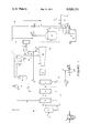
- FIG. 1 The sole drawing (FIG. 1) is a flow sheet for a geothermal power plant constituting a preferred embodiment of the present invention in which a multi-stage turbine is powered with motive steam obtained by flashing a preflashed brine.
- geothermal brines According to Sigvaldason (see the Unesco publication cited earlier herein), geothermal brines have been arbitrarily classified into several main types, according to their predominant mineral components:
- Acid sulphate/chloride brines having relatively high ratios of bisulphate to chloride ions are rare and their acidity is attributed to oxidation of sulphide to bisulphate, at depth.
- Acid sulphate brines are common in fumaroles. Their acidity is attributed to oxidation of H 2 S to H 2 SO 4 and their chloride contents are very low.
- Calcium bicarbonate brines occur as warm springs, precipitate calcite and are too cool to be economically processable.
- More than one type of brine can occur within a given geothermal system and the composition of the thermal gases (other than steam) associated with a given brine type can vary. Three main types of thermal gases are discernible:
- thermal gases include methane, Argon, ammonia and H 3 BO 3 .
- FIG. 1 a representative plant embodying the present invention will now be described (except for such conventional items as control instrumentation, valves, etc.). Small case letters are used to designate various streams for which typical temperatures, heat contents, pressures, flow rates, compositions, etc. are given in a subsequent tabulation herein.
- a hot brine (a), containing non-condensible gases, is produced from a geothermal well 1 and introduced to flash vessel 2 wherein it is preflashed to form a hot vapor stream (b) and a hot liquid stream (c).
- Vapor stream (b) is utilized, in heat exchangers 10, 11 and 12, respectively, to heat streams e, (h+ 1) and (j+ n) and in steam ejectors 13 and 14 to maintain exhaust vacuum for turbine 20.
- the portion of stream (b) condensed in exchanger 10 is subsequently separated in vessel 6 and the condensate formed in exchangers 11 and 12 is subsequently separated in vessel 7.
- Hot liquid stream (c) and (s) are combined and flashed (as stream d) in vessel 3.
- the resulting vapor stream (e) is superheated in exchanger 10 and introduced (as g) to the first stage of turbine 20.
- the hot liquid (f) from vessel 3 is reflashed in vessel 4 to form vapor stream (h), which is combined with the exhaust (l) from the first stage of turbine 20, reheated in exchanger 11 and introduced (as m) to the second stage of the turbine.
- the liquid (i) from vessel 4 is finally flashed in vessel 5 and the resulting vapor stream (j) is combined with the exhaust (n) from the second stage of the turbine, reheated in exchanger 12 and introduced (as o) to the third stage of turbine 20.
- the final exhaust (p) is quenched (by stream q) in vessel 8, which is maintained at a reduced pressure by ejectors 13 and 14 to ensure removal of any non-condensibles present in (p).
- the liquid condensate is dumped to sump 18, and transferred by pump 16 to cooling tower 9, from which stream q is taken by pump 17.
- the vapor stream from vessel 8 is combined with the portions of (b) introduced to ejectors 13 and 14, with the vapor stream from vessel 6 and with the liquid (k) from vessel 5 to form a cool, reconstituted brine which is returned to the aquifer by pump 15 through an injection well 19. (The latter well is located at a sufficient distance from any production wells, such as 1, to avoid undue cooling of the producing zone.) Electric power is produced by generator 21, driven by turbine 20.
- Stream r is the fan driven, wet air exhaust from cooling tower 9.
- the gas stream which is combined with liquid stream (k) to form the reconstituted brine is under a pressure of about 30 psia.
- compositions, flow rates, heat contents, temperatures and pressures are given for operation of the plant of FIG. 1 to produce 63,547 K.W. of power (gross) from 15000 gallons per minute of brine issuing from well 1 in which bottom-hole conditions are 412° F. and 285 psia.
- the tabulated quantities are calculated with the aid of a standard Mollier diagram by methods well known to those skilled in the art.
- the net power produced (59,747 K.W.) is calculated by subtracting 3800 K.W. for internal power requirements (pumps 15, 16 and 17 and the cooling tower fans-- not shown) from the gross.
- a compressor (not shown in FIG. 1) may be required in order to effect redissolution of the gaseous components of the reconstituted (cool) brine and reinjection into the aquifer. In this event, a further reduction in net power production will of course result.
- FIG. 1 and the foregoing description are for purposes of illustration and are not to be construed as restricting the scope of the present invention to a greater extent than the claims accompanying this specification. Those skilled in the art will recognize that various modes of operation, alternative to that depicted in FIG. 1, are within the ambit of the invention.
- the vapor stream from the pre-flash after being utilized to superheat and reheat the motive steam and separated from the resulting condensate, may be further utilized to reheat said condensate (and other condensates) and then processed for selective removal of obnoxious gases such as H 2 S and vented, without being used to operate steam injectors or reinjected into the aquifer.
- the reheated condensates being essentially free of non-condensibles, may be combined with the motive steam (from a first flash for same) prior to superheating.
- the final condensate (from the pre-flash vapor stream) may be combined with the liquid feed to a subsequent flash from which motive steam is obtained for use (in combination with the exhaust from the first stage of a two-stage turbine; reheated) in the second stage of the turbine.
- a portion of the vapor from the first motive steam flash may be used to operate the steam injectors. Cooling of the water used to quench the final exhaust may be effected in an evaporation pond, rather than in a cooling tower.
- the calculated net power production for a plant incorporating the preceding alternatives and operated on 6,000,000 pounds per hour of a 500° F., 3550 psia brine containing 17% NaCl, 3% CO 2 and 0.0033% H 2 S is 50,000 K.W.
Abstract
Heat energy is more efficiently recovered from geothermal brines by preflashing the brine to remove dissolved, non-condensible gases before flashing the brine to produce motive steam. Power requirements for removal of non-condensibles from turbine exhausts (in order to maintain adequately low exhaust pressures) are obviated. The heat content of the pre-flashed vapors may be largely utilized for superheating and reheating the motive steam.
Description
1. Field of the Invention
This invention relates to the recovery of heat energy from geothermal aquifers.
2. Description of the Prior Art
The prior art pertinent to the present invention is believed to be limited to the technology which has been adapted to or developed in conjunction with recovery of thermal energy from geothermal brines.
The known art involved in the utilization of geothermal brines is summarized in number 12 of a series of publications by the Unesco Press on earth sciences; Geothermal Energy, Review of Research and Development (The Unesco Press, 7 Place de Fontenoy, 75700 Paris, France; (1973)).
Brines obtained from naturally heated aquifers have been utilized for various purposes since at least as early as ancient Rome. The most dramatic and best known use for geothermal energy is electric power generation, as practiced in Italy, Japan, Iceland, New Zealand, Mexico and the United States (California). In some locations, "dry" steam, produced as such from geothermal wells, is employed for this purpose. In other locations, wet steam, present as such in a geothermal formation or formed by flashing of hot brines, is used.
Most geothermal fluids, steam and hot water, contain dissolved non-condensible gases. Existing geothermal power processes utilizing hot water or brines often flash the fluid to produce motive steam which is then used in a steam turbine for production of electricity. The vast majority of the non-condensible gases present in the geothermal fluid are consequently flashed into the motive steam. The steam exhausting from the turbine is condensed under varying vacuum conditions. The non-condensible gases must be removed from the exhaust steam in order to maintain the desired vacuum in the turbine exhaust system. The equipment required to remove the non-condensibles can require a significant amount of power in the form of either motive steam for steam power ejectors, or mechanical power for vacuum pumps. Thermodynamic efficiency can be severely constrained as the percentage of non-condensible gases increases.
Some non-condensible gas components, such as hydrogen sulfide, are too obnoxious to be discharged to the atmosphere. Thus, when brines containing such gases are flashed to provide motive steam, the non-condensibles separated from the turbine exhaust cannot simply be vented to the atmosphere without additional treatment.
Pretreatment of geothermal brines or of steam produced therefrom has heretofore been limited to such practices as scrubbing of steam (at Wairakei, New Zealand) to remove entrained brine droplets. It has not previously been proposed to remove non-condensibles from hot waters or brines, otherwise suitable as sources of motive steam.
A primary object of the present invention is to effect an increase in the thermodynamic efficiency of a conventional method of utilizing geothermal brines as direct sources of motive steam.
An additional object is to provide a method of removing non-condensible gases from geothermal brines which is particularly well adapted to use with multi-stage turbines powered by steam produced from such brines.
A further object is to provide an improved system for obtaining mechanical or electrical power from geothermal brines containing dissolved, non-condensible gases.
Another object is to reduce erosion and corrosion of turbine blades and other equipment contacts with steam derived from such brines.
It is also an object to facilitate non-polluting disposal of non-condensible gases containing obnoxious components.
Still other objects will be made apparent to those skilled in the art by the following disclosure.
The present invention is an improved process for producing motive steam by flashing of hot brines containing non-condensible gases, said improvement comprising:
(a) preflashing said brine to produce a hot vapor phase enriched in said gases and a hot liquid phase depleted therein, and
(b) producing said motive steam by flashing said hot liquid phase.
In a preferred mode of operation, the pre-flash is carried out in such manner that the content of non-condensibles in the resulting liquid phase is reduced below a pre-selected level.
In another preferred mode of operation, the vapor phase produced in the pre-flash is used to superheat the motive steam produced upon subsequent flashing of the liquid phase, thereby increasing the quality of the motive steam and reducing the potential for turbine blade erosion. Preferably, heat then remaining in the preflashed vapor phase is utilized to reheat the motive steam as it passes from stage to stage of a multi-stage turbine.
The sole drawing (FIG. 1) is a flow sheet for a geothermal power plant constituting a preferred embodiment of the present invention in which a multi-stage turbine is powered with motive steam obtained by flashing a preflashed brine.
According to Sigvaldason (see the Unesco publication cited earlier herein), geothermal brines have been arbitrarily classified into several main types, according to their predominant mineral components:
(1) Sodium chloride brines (the most common type in large aquifers) are generally neutral at depth but become somewhat alkaline upon losing steam and CO2 ; the ratio of Cl- to SO4 = is high in these brines;
(2) Acid sulphate/chloride brines, having relatively high ratios of bisulphate to chloride ions are rare and their acidity is attributed to oxidation of sulphide to bisulphate, at depth.
(3) Acid sulphate brines are common in fumaroles. Their acidity is attributed to oxidation of H2 S to H2 SO4 and their chloride contents are very low.
(4) Calcium bicarbonate brines occur as warm springs, precipitate calcite and are too cool to be economically processable.
More than one type of brine can occur within a given geothermal system and the composition of the thermal gases (other than steam) associated with a given brine type can vary. Three main types of thermal gases are discernible:
(1) High nitrogen content; little or none of active gases;
(2) Very high CO2 and minimal H2 S and H2 contents;
(3) High contents of H2, H2 S and CO2.
Other constituents of thermal gases are methane, Argon, ammonia and H3 BO3.
The dependency of solubility equilibria between various mineral and gaseous components of brines on temperature and pressure is quite complex. Consequently, it is difficult to predict how much flashing or stripping of a given brine can be permitted to occur without experiencing precipitation of silica, calcite, etc. However, the occurrence or non-occurrence of precipitation is independent and not controlling of the practice of the present invention. So long as the amount and character of any precipitate formed during the pre-flash step is not such as to interfere to an intolerable extent with subsequent utilizaton of the water contained in the resultant slurry, the process is operable. Pre-flash and subsequent operating conditions most favorable to avoiding or satisfactorily handling precipitates may readily be determined by means of test procedures familiar to those skilled in the art.
Referring now to FIG. 1, a representative plant embodying the present invention will now be described (except for such conventional items as control instrumentation, valves, etc.). Small case letters are used to designate various streams for which typical temperatures, heat contents, pressures, flow rates, compositions, etc. are given in a subsequent tabulation herein.
A hot brine (a), containing non-condensible gases, is produced from a geothermal well 1 and introduced to flash vessel 2 wherein it is preflashed to form a hot vapor stream (b) and a hot liquid stream (c). Vapor stream (b) is utilized, in heat exchangers 10, 11 and 12, respectively, to heat streams e, (h+ 1) and (j+ n) and in steam ejectors 13 and 14 to maintain exhaust vacuum for turbine 20. The portion of stream (b) condensed in exchanger 10 is subsequently separated in vessel 6 and the condensate formed in exchangers 11 and 12 is subsequently separated in vessel 7. Hot liquid stream (c) and (s) are combined and flashed (as stream d) in vessel 3. The resulting vapor stream (e) is superheated in exchanger 10 and introduced (as g) to the first stage of turbine 20.
The hot liquid (f) from vessel 3 is reflashed in vessel 4 to form vapor stream (h), which is combined with the exhaust (l) from the first stage of turbine 20, reheated in exchanger 11 and introduced (as m) to the second stage of the turbine. Similarly, the liquid (i) from vessel 4 is finally flashed in vessel 5 and the resulting vapor stream (j) is combined with the exhaust (n) from the second stage of the turbine, reheated in exchanger 12 and introduced (as o) to the third stage of turbine 20. The final exhaust (p) is quenched (by stream q) in vessel 8, which is maintained at a reduced pressure by ejectors 13 and 14 to ensure removal of any non-condensibles present in (p). The liquid condensate is dumped to sump 18, and transferred by pump 16 to cooling tower 9, from which stream q is taken by pump 17. The vapor stream from vessel 8 is combined with the portions of (b) introduced to ejectors 13 and 14, with the vapor stream from vessel 6 and with the liquid (k) from vessel 5 to form a cool, reconstituted brine which is returned to the aquifer by pump 15 through an injection well 19. (The latter well is located at a sufficient distance from any production wells, such as 1, to avoid undue cooling of the producing zone.) Electric power is produced by generator 21, driven by turbine 20. Stream r is the fan driven, wet air exhaust from cooling tower 9.
The gas stream which is combined with liquid stream (k) to form the reconstituted brine is under a pressure of about 30 psia.
In the following table, compositions, flow rates, heat contents, temperatures and pressures are given for operation of the plant of FIG. 1 to produce 63,547 K.W. of power (gross) from 15000 gallons per minute of brine issuing from well 1 in which bottom-hole conditions are 412° F. and 285 psia. The tabulated quantities are calculated with the aid of a standard Mollier diagram by methods well known to those skilled in the art. The net power produced (59,747 K.W.) is calculated by subtracting 3800 K.W. for internal power requirements (pumps 15, 16 and 17 and the cooling tower fans-- not shown) from the gross.
A compressor (not shown in FIG. 1) may be required in order to effect redissolution of the gaseous components of the reconstituted (cool) brine and reinjection into the aquifer. In this event, a further reduction in net power production will of course result.
                                  TABLE I
__________________________________________________________________________
Stream      a    b    c     d     e     f     g     h     i
__________________________________________________________________________
Component-M lbs./Hour
Water      6607.4
                267.3
                     6340.2
                           6490.1
                                 458.  6032.1
                                             458.  371.0 5661.
CO.sub.2   2.54 2.41 .1    .1    .1    --    .1    --    --
H.sub.2 S  .02  .02  --    --    --    --    --    --    --
Total M lbs./Hour
           6610.
                269.7
                     6340.3
                           6490.2
                                 458.1 6032.1
                                             458.1 371.0 5661.
Enthalpy - BTU/lb.
           388.1
                1198.
                     353.6 353.6 1185.2
                                       290.4 1207.4
                                                   1168.7
                                                         232.8
Temperature - ° F.
           412. 380. 380.  380.  320.  320.  360.  264.  264.
Pressure - psia
           285. 196. 196.  196.  90.   90.   88.   38.   38.
Stream      j    k    l    m    n    o    p    q    r     s
__________________________________________________________________________
Component-M lbs./Hour
Water      307.2
                5353.8
                     458.0
                          829.0
                               829.0
                                    1136.2
                                         1136.2
                                              38500
                                                   1156.0
                                                         149.1
CO.sub.2   --   --   --   --   --   --   --   --   --    --
H.sub. 2 S --   --   --   --   --   --   --   --   --    --
Total - M lbs./Hour
           307.2
                5353.8
                     458.0
                          829.0
                               829.0
                                    1136.2
                                         1136.2
                                              38500
                                                   1156.0
                                                         149.1
Enthalpy - BTU/lb.
           1150.5
                180. 1163.4
                          1215.
                               1151.
                                    1220.
                                         1083.5
                                              --   --    353.6
Temperature - ° F.
           212. 212. 264. 360. 213. 360. 100. 70   86° F.
                                                         380° F.
Pressure - psia
           14.7 14.7 38.  36.  14.7 12.7 .95  --   ATM   196.
__________________________________________________________________________
FIG. 1 and the foregoing description are for purposes of illustration and are not to be construed as restricting the scope of the present invention to a greater extent than the claims accompanying this specification. Those skilled in the art will recognize that various modes of operation, alternative to that depicted in FIG. 1, are within the ambit of the invention.
For example, the vapor stream from the pre-flash, after being utilized to superheat and reheat the motive steam and separated from the resulting condensate, may be further utilized to reheat said condensate (and other condensates) and then processed for selective removal of obnoxious gases such as H2 S and vented, without being used to operate steam injectors or reinjected into the aquifer. The reheated condensates, being essentially free of non-condensibles, may be combined with the motive steam (from a first flash for same) prior to superheating. The final condensate (from the pre-flash vapor stream) may be combined with the liquid feed to a subsequent flash from which motive steam is obtained for use (in combination with the exhaust from the first stage of a two-stage turbine; reheated) in the second stage of the turbine. A portion of the vapor from the first motive steam flash may be used to operate the steam injectors. Cooling of the water used to quench the final exhaust may be effected in an evaporation pond, rather than in a cooling tower.
The calculated net power production for a plant incorporating the preceding alternatives and operated on 6,000,000 pounds per hour of a 500° F., 3550 psia brine containing 17% NaCl, 3% CO2 and 0.0033% H2 S is 50,000 K.W.
Claims (4)
1. An improved method of driving a turbine with motive steam produced from a hot brine which contains non-condensible gases, said improvement comprising:
(a) preflashing said brine to produce a hot vapor phase enriched in said gases and a hot liquid phase depleted therein,
(b) producing said motive steam by flashing said hot liquid phase, and
(c) driving said turbine solely with said motive steam.
2. The process of claim 1 in which the content of non-condensibles in said hot liquid phase is reduced below a preselected level.
3. The process of claim 1 in which said hot vapor phase is used to superheat said motive steam.
4. The process of claim 3 in which said hot vapor phase is also used to reheat the motive steam as it passes from stage to stage of a multi-stage turbine.
Priority Applications (1)
| Application Number | Priority Date | Filing Date | Title |
|---|---|---|---|
| US05/654,826 US4026111A (en) | 1976-02-03 | 1976-02-03 | Method of removing dissolved non-condensibles from geothermal brines |
Applications Claiming Priority (1)
| Application Number | Priority Date | Filing Date | Title |
|---|---|---|---|
| US05/654,826 US4026111A (en) | 1976-02-03 | 1976-02-03 | Method of removing dissolved non-condensibles from geothermal brines |
Publications (1)
| Publication Number | Publication Date |
|---|---|
| US4026111A true US4026111A (en) | 1977-05-31 |
Family
ID=24626402
Family Applications (1)
| Application Number | Title | Priority Date | Filing Date |
|---|---|---|---|
| US05/654,826 Expired - Lifetime US4026111A (en) | 1976-02-03 | 1976-02-03 | Method of removing dissolved non-condensibles from geothermal brines |
Country Status (1)
| Country | Link |
|---|---|
| US (1) | US4026111A (en) |
Cited By (17)
| Publication number | Priority date | Publication date | Assignee | Title |
|---|---|---|---|---|
| US4144715A (en) * | 1977-08-24 | 1979-03-20 | Union Oil Company Of California | Method of producing mechanical energy from geothermal fluids |
| US4189923A (en) * | 1978-03-22 | 1980-02-26 | Clyde Berg | Geothermal energy recovery |
| US4244190A (en) * | 1978-10-23 | 1981-01-13 | Union Oil Company Of California | Process for integrating treatment of and energy derivation from geothermal brine |
| US4308722A (en) * | 1979-06-08 | 1982-01-05 | Molini Alberto E | Recovery of enthalpy from hot industrial effluents |
| US4407127A (en) * | 1980-09-22 | 1983-10-04 | Tokyo Shibaura Denki Kabushiki Kaisha | Flashing apparatus of geothermal power plants |
| US4448024A (en) * | 1979-06-08 | 1984-05-15 | Molini Alberto E | Recovery of enthalpy from hot fluids |
| US4492083A (en) * | 1980-07-18 | 1985-01-08 | Magma Power Company | Geothermal salinity control system |
| FR2551430A1 (en) * | 1983-08-31 | 1985-03-08 | Superior Thermal Inc | Process and apparatus for converting gaseous water into pure saturated steam |
| US4512851A (en) * | 1983-02-15 | 1985-04-23 | Swearingen Judson S | Process of purifying a recirculating working fluid |
| US5479818A (en) * | 1992-08-10 | 1996-01-02 | Dow Deutschland Inc. | Process for detecting fouling of an axial compressor |
| US5541857A (en) * | 1992-08-10 | 1996-07-30 | Dow Deutschland Inc. | Process and device for monitoring vibrational excitation of an axial compressor |
| US5594665A (en) * | 1992-08-10 | 1997-01-14 | Dow Deutschland Inc. | Process and device for monitoring and for controlling of a compressor |
| US5612497A (en) * | 1992-08-10 | 1997-03-18 | Dow Deutschland Inc. | Adaptor for monitoring a pressure sensor to a gas turbine housing |
| USRE36282E (en) * | 1990-12-12 | 1999-08-31 | Nitschke; George S. | System for using geopressured-geothermal reservoirs |
| US20140075938A1 (en) * | 2012-09-14 | 2014-03-20 | Ormat Technologies Inc. | Method and apparatus for producing power from geothermal fluid |
| RU2528776C1 (en) * | 2013-03-05 | 2014-09-20 | Федеральное Государственное Бюджетное Образовательное Учреждение Высшего Профессионального Образования "Дагестанский Государственный Технический Университет" (Дгту) | Method of cleaning heat exchanger from carbonate deposits |
| EP3364131A1 (en) | 2014-04-04 | 2018-08-22 | Climeon AB | Removal of non-condensble gases from a closed-loop process |
Citations (4)
| Publication number | Priority date | Publication date | Assignee | Title |
|---|---|---|---|---|
| US3605403A (en) * | 1969-09-24 | 1971-09-20 | Mitsubishi Heavy Ind Ltd | Transporting means and equipment for jet energy of geothermal power plant |
| US3862545A (en) * | 1972-10-24 | 1975-01-28 | Chevron Res | Geothermal brine energy to generate power |
| US3893299A (en) * | 1972-10-26 | 1975-07-08 | Geothermal Investment Co | Geothermal heat recovery by multiple flashing |
| US3908381A (en) * | 1974-11-20 | 1975-09-30 | Sperry Rand Corp | Geothermal energy conversion system for maximum energy extraction |
-
1976
- 1976-02-03 US US05/654,826 patent/US4026111A/en not_active Expired - Lifetime
Patent Citations (4)
| Publication number | Priority date | Publication date | Assignee | Title |
|---|---|---|---|---|
| US3605403A (en) * | 1969-09-24 | 1971-09-20 | Mitsubishi Heavy Ind Ltd | Transporting means and equipment for jet energy of geothermal power plant |
| US3862545A (en) * | 1972-10-24 | 1975-01-28 | Chevron Res | Geothermal brine energy to generate power |
| US3893299A (en) * | 1972-10-26 | 1975-07-08 | Geothermal Investment Co | Geothermal heat recovery by multiple flashing |
| US3908381A (en) * | 1974-11-20 | 1975-09-30 | Sperry Rand Corp | Geothermal energy conversion system for maximum energy extraction |
Cited By (21)
| Publication number | Priority date | Publication date | Assignee | Title |
|---|---|---|---|---|
| US4144715A (en) * | 1977-08-24 | 1979-03-20 | Union Oil Company Of California | Method of producing mechanical energy from geothermal fluids |
| US4189923A (en) * | 1978-03-22 | 1980-02-26 | Clyde Berg | Geothermal energy recovery |
| US4244190A (en) * | 1978-10-23 | 1981-01-13 | Union Oil Company Of California | Process for integrating treatment of and energy derivation from geothermal brine |
| US4420938A (en) * | 1978-10-23 | 1983-12-20 | Union Oil Company Of California | Geothermal power plant |
| US4308722A (en) * | 1979-06-08 | 1982-01-05 | Molini Alberto E | Recovery of enthalpy from hot industrial effluents |
| US4448024A (en) * | 1979-06-08 | 1984-05-15 | Molini Alberto E | Recovery of enthalpy from hot fluids |
| US4492083A (en) * | 1980-07-18 | 1985-01-08 | Magma Power Company | Geothermal salinity control system |
| US4407127A (en) * | 1980-09-22 | 1983-10-04 | Tokyo Shibaura Denki Kabushiki Kaisha | Flashing apparatus of geothermal power plants |
| US4512851A (en) * | 1983-02-15 | 1985-04-23 | Swearingen Judson S | Process of purifying a recirculating working fluid |
| FR2551430A1 (en) * | 1983-08-31 | 1985-03-08 | Superior Thermal Inc | Process and apparatus for converting gaseous water into pure saturated steam |
| USRE36282E (en) * | 1990-12-12 | 1999-08-31 | Nitschke; George S. | System for using geopressured-geothermal reservoirs |
| US5479818A (en) * | 1992-08-10 | 1996-01-02 | Dow Deutschland Inc. | Process for detecting fouling of an axial compressor |
| US5594665A (en) * | 1992-08-10 | 1997-01-14 | Dow Deutschland Inc. | Process and device for monitoring and for controlling of a compressor |
| US5612497A (en) * | 1992-08-10 | 1997-03-18 | Dow Deutschland Inc. | Adaptor for monitoring a pressure sensor to a gas turbine housing |
| US5541857A (en) * | 1992-08-10 | 1996-07-30 | Dow Deutschland Inc. | Process and device for monitoring vibrational excitation of an axial compressor |
| US20140075938A1 (en) * | 2012-09-14 | 2014-03-20 | Ormat Technologies Inc. | Method and apparatus for producing power from geothermal fluid |
| WO2014041417A2 (en) * | 2012-09-14 | 2014-03-20 | Ormat Technologies Inc. | Method and apparatus for producing power from geothermal fluid |
| WO2014041417A3 (en) * | 2012-09-14 | 2014-05-22 | Ormat Technologies Inc. | Method and apparatus for producing power from geothermal fluid |
| US9388797B2 (en) * | 2012-09-14 | 2016-07-12 | Ormat Technologies, Inc. | Method and apparatus for producing power from geothermal fluid |
| RU2528776C1 (en) * | 2013-03-05 | 2014-09-20 | Федеральное Государственное Бюджетное Образовательное Учреждение Высшего Профессионального Образования "Дагестанский Государственный Технический Университет" (Дгту) | Method of cleaning heat exchanger from carbonate deposits |
| EP3364131A1 (en) | 2014-04-04 | 2018-08-22 | Climeon AB | Removal of non-condensble gases from a closed-loop process |
Similar Documents
| Publication | Publication Date | Title |
|---|---|---|
| US4026111A (en) | Method of removing dissolved non-condensibles from geothermal brines | |
| US3215189A (en) | Evaporative process using submerged combustion | |
| JP3391515B2 (en) | Apparatus and method for obtaining power from high pressure geothermal fluid | |
| US4996846A (en) | Method of and apparatus for retrofitting geothermal power plants | |
| JP4762555B2 (en) | Power generation desalination method | |
| US5598706A (en) | Method of and means for producing power from geothermal fluid | |
| US5557936A (en) | Thermodynamic power generation system employing a three component working fluid | |
| CA1123617A (en) | Power generation by exchange of latent heats of phase transition | |
| US5809782A (en) | Method and apparatus for producing power from geothermal fluid | |
| EP0372864A1 (en) | Method of and apparatus for producing power using steam | |
| EP0604718A2 (en) | Evaporative salt plant | |
| US4057964A (en) | Working fluids and systems for recovering geothermal or waste heat | |
| BRPI0924205B1 (en) | METHOD FOR SEPARATING CARBON DIOXIDE FROM EXHAUST GAS FROM A FOSSIL ENERGY POWER PLANT. | |
| Spadacini et al. | Geothermal energy exploitation with Organic Rankine Cycle technologies | |
| US3893299A (en) | Geothermal heat recovery by multiple flashing | |
| Awerbuch et al. | Geothermal energy recovery process | |
| Manente et al. | Low emission flash-binary and two-phase binary geothermal power plants with water absorption and reinjection of non-condensable gases | |
| EP2470754A1 (en) | Method and system for generating high pressure steam | |
| US5400598A (en) | Method and apparatus for producing power from two-phase geothermal fluid | |
| JPH03906A (en) | Feed water preheating method and device in steam generating plant | |
| JPH09502233A (en) | Geothermal / fossil fuel combined use power plant | |
| US4163044A (en) | Method for removing hydrogen sulfide from steam | |
| JPS5918556B2 (en) | Method and apparatus for extracting and using thermal energy from brine in geothermal wells | |
| CN111420516A (en) | Steam waste heat cascade utilization system for carbon capture absorbent regeneration system | |
| JPS61201831A (en) | Power generation method |