US3441218A - Adjustable nozzle for jet propulsion engine - Google Patents
Adjustable nozzle for jet propulsion engine Download PDFInfo
- Publication number
- US3441218A US3441218A US592635A US3441218DA US3441218A US 3441218 A US3441218 A US 3441218A US 592635 A US592635 A US 592635A US 3441218D A US3441218D A US 3441218DA US 3441218 A US3441218 A US 3441218A
- Authority
- US
- United States
- Prior art keywords
- ring
- tube
- rings
- section
- adjustable nozzle
- Prior art date
- Legal status (The legal status is an assumption and is not a legal conclusion. Google has not performed a legal analysis and makes no representation as to the accuracy of the status listed.)
- Expired - Lifetime
Links
Images

Classifications
-
- F—MECHANICAL ENGINEERING; LIGHTING; HEATING; WEAPONS; BLASTING
- F02—COMBUSTION ENGINES; HOT-GAS OR COMBUSTION-PRODUCT ENGINE PLANTS
- F02K—JET-PROPULSION PLANTS
- F02K1/00—Plants characterised by the form or arrangement of the jet pipe or nozzle; Jet pipes or nozzles peculiar thereto
- F02K1/40—Nozzles having means for dividing the jet into a plurality of partial jets or having an elongated cross-section outlet
- F02K1/42—Nozzles having means for dividing the jet into a plurality of partial jets or having an elongated cross-section outlet the means being movable into an inoperative position
-
- F—MECHANICAL ENGINEERING; LIGHTING; HEATING; WEAPONS; BLASTING
- F02—COMBUSTION ENGINES; HOT-GAS OR COMBUSTION-PRODUCT ENGINE PLANTS
- F02K—JET-PROPULSION PLANTS
- F02K1/00—Plants characterised by the form or arrangement of the jet pipe or nozzle; Jet pipes or nozzles peculiar thereto
- F02K1/06—Varying effective area of jet pipe or nozzle
- F02K1/08—Varying effective area of jet pipe or nozzle by axially moving or transversely deforming an internal member, e.g. the exhaust cone
Definitions
- An adjustable nozzle construction for a jet engine The nozzle construction is progressively adjusted between a maximum thrust position and a minimum thrust position. Means is provided for instituting and adjusting drag to facilitate smooth control of jet propulsive thrust of the engine.
- the exhaust nozzle includes axially movable frusto-conical rings for adjusting propulsive thrust of the jet propulsion unit.
- a tapered frusto-conical rear end section is provided on a cylindrical exhaust tube.
- a first frustroconical ring is movably disposed in the rear end section and has a narrow rear end extending rearwardly beyond the rear end section of the tube.
- a second frusto-conical ring is disposed similarly to the first frusto-conical ring in alignment with the first ring with a narrow rear end extending rearwardly beyond the end of the first ring.
- Motor means is operatively connected to the first and second rings for independently and selectively extending the rings rearwardly and retracting the rings forwardly to provide exhaust openings of controllable size, whereby the propulsive thrust is determined by the relative positioning or the rings axially of the tube and of each other.
- One object of the invention is to provide an adjustable nozzle construction for a jet engine, in which the nozzle can be progressively adjusted between a maximum thrust position and a minimum thrust position.
- a further object is to provide an adjustable nozzle construction as described, with means for instituting and adjusting drag to facilitate smooth control of jet propulsive thrust of the engine.
- Still another object is to provide a jet propulsion unit with an exhaust nozzle including axially movable frustoconical rings for adjusting propulsive thrust of the unit.
- Another object is to provide a jet propulsion unit as described with lateral openings for causing drag, and means for adjustably closing the openings to regulate the drag.
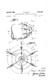
- FIGURE 1 is a side view of part of a jet propelled unit equipped with a nozzle assembly embodying the invention, the assembly being shown in extended position.
- FIG. 2 is an enlarged elevational end view taken on line 22 of FIG. 1.
- FIG. 3 is a longitudinal sectional view taken on line 3-3 of FIG. 1.
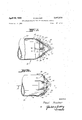
- FIG. 4 is a side view similar to FIG. 1, with the nozzle assembly shown in retracted position.
- FIG. 5 is a longitudinal sectional view similar to FIG. 3, but taken on line 55 of FIG. 4.
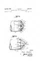
- FIG. 6 is a side view similar to FIG. 1, showing another nozzle assembly.
- FIG. 7 is an enlarged fragmentary sectional view taken on line 7-7, showing the nozzle assembly in fully retracted position.
- FIGS. 8 and 9 are two sectional views similar to FIG. 7, showing the nozzle assembly in two different intermediate positions.
- FIG. 10 is a sectional view similar to FIGS. 7-9, showing the nozzle assembly in fully extended position.
- FIGS. l-S there is shown part of an exhaust tube 20 of a jet propulsion unit 10.
- the tube 20 has a generally conical open rear end section 22.
- a frusto-conical ring 24 is axially aligned with tube 20 and is axially movable in end section 22 of the tube.
- a second ring 26 of smaller size is axially aligned with tube 20 and ring 24 and is disposed in ring 24.
- Ring 24 is movable axially by a plurality of hydraulic motors 28 pivotally mounted on "brackets 32 attached to tube section 22.
- the motors are spaced apart circumferentially of the tube.
- Their piston shafts 34 are pivotally engaged on arms 36 projecting radially outward of ring 24.
- Ring 26 is movable axially by a plurality of hydraulic motors 37 pivotally mounted on brackets 40 attached to tube section 22. Motors 37 are also spaced apart 120 circumferentially of the tube and have long piston shafts 42 engaged on arms 44 attached to ring 26.
- a ring 46 supported centrally of the tube by radial spider arms 48. Extending rearwardly from ring 46 axially of the tube is a shaft 50. Shaft 50 extends through ring 24 and partially through ring 26. A short sleeve 52 is centrally supported by radial arms 54 in ring 24. This sleeve is slidably disposed on shaft 50 which extends through the sleeve. A second sleeve 56 is centrally supported by radial arms 58 in ring 26. Sleeve 54 is slidably disposed inside of sleeve 56.
- ring 24 surrounds the forward part of ring 26 which projects rearwardly out of ring 24.
- Tube section 22 surrounds the forward part of ring 24 which projects rearwardly of the tube section 22.
- each motor has two spaced hydraulic lines 60, 62 connected thereto for driving the piston shaft rearwardly and for retracting the shaft when fluid in the lines is driven into and out of the motor from a forwardly controlled fluid supply (not shown).
- the nozzle assembly including the rings and tube section has a rear opening 65 of minimum size limited only to the opening in ring 26.
- the exhaust gas has maximum velocity at this point and consequently maximum forward thrust is applied to the unit of which tube 20 is a part.
- annular channel 64 is open between ring 24 and tube section 22.
- Another annular channel 66 is open between rings 24 and 26.
- the rear and exhaust outlet of tube 20 is enlarged by channels 64 and 66 so that the expulsion velocity of exhaust gas is less than in the fully extended positions of the rings, and forward thrust of tube 20 is minimum.
- the motors 28 and 37 can be selectively operated so that at intermediate positions either one of channels 64, 66 can be opened to greater or lesser extent as desired. Thus a smooth adjustment can be effected between minimum and maximum exhaust openings for varying the forward thrust of the propulsion unit.
- the centered fixed shaft 50 and sleeves 52, 56 keep the rings properly centered within the tube.
- the rings and tube section 22 have the same apical angle A and have such sizes that when fully extended they laterally abut each other and ringsection 22 to close off both annular channels 64, 66.
- FIGS. 6-10 is shown part of another propulsion unit 10A which is generally similar to unit 10 and corresponding parts are identically numbered.
- tube section 22a of tube a there are provided lateral ports or vents 70 spaced apart circumferentially of the ring section.
- the ports are disposed near the rear end of the ring section 22a so that they will be closed when ring 24 is fully extended rearwardly as shown in FIGS. 8 and 10.
- FIGS. 7 and 9 When ring 24 is partially or fully retracted as shown in FIGS. 7 and 9, then some exhaust gas is discharged laterally of the tube and causes a drag which effectively slows down forward thrust.
- ring 24 closes the ports 70 while ring 26 is partially or fully retracted as shown in FIG. 10, this constitutes an intermediate position of the nozzle assembly.
- channel 66 is open between rings 24 and 26.
- ring 26 is fully extended from ring 24 as shown in FIG. 9, while ring 24 is partially or fully retracted, this constitutes another intermediate position with some lateral discharge and drag subtracting from the intermediate forward thrust due to fully open ring 26 and annular channel 64 between ring 24 and tube section 22a.
- the sets of motors moving rings 24, 26 are independently adjustable so either or both rings can be extended or retracted.
- the rings 24, 26 of propulsion unit 10 shown in FIGS. 1-5 are also disposable in the plurality of intermediate positions shown in FIGS. 8 and 9, except that there will be no lateral exhaust gas discharge and thus no drag.
- the ports 70 will be reduced in number or omitted.
- the invention provides means for selectively controlling forward thrust and drag by adjustably positioning the rings 24, 26 axially of the propulsion unit.
- An adjustable nozzle assembly for a jet propulsion unit having a cylindrical exhaust tube through which engine exhaust gases discharge for providing forward propulsive thrust; said assembly comprising a tapered frustoconical rear end section on said tube, a first frusto-conical ring movably disposed in said end section of the tube in axial alignment therewith and having a narrow rear end extending rearwardly beyond said end section of the tube, a second frusto-conical ring movably disposed in said end section of the tube in axial alignment therewith and having a narrow rear and extending rearwardly beyond the end of the first frusto-conical ring, and motor means carried by said tube and operatively engaged with both of said rings for independently and selectively extending the rings rearwardly and retracting the rings forwardly to provide exhaust openings of controllable size, whereby the propulsive thrust is determined by the relative positioning of the rings axially of said tube and of each other.
- An adjustable nozzle assembly according to claim 1, further comprising means for holding the rings in axial alignment with the tube in all relative axial positions of the rings.
- An adjustable nozzle assembly according to claim 1, wherein the same apical angle is defined by the rings and ring section so that in the fully extended positions of the rings, the outer side of the first ring snugly engages the inside of the ring section and the outer side of the second ring snugly engages the inside of the first ring, whereby the opening in the second ring is then the only outlet for discharge gas so that maximum forward propulsive force is exerted on said unit, and whereby annular channels are open between the first ring and ring section, and between the first and second rings when the rings are retracted with respect to the tube.
- said holding means for the rings comprises an axial shaft supported in a fixed position in said ring section and extending rearwardly through the aligned first and second rings, a first sleeve centrally supported in the first ring and slidably engaged on said shaft, and a second sleeve centrally supported in the second ring and slidably engaged on the first sleeve, whereby the rings are held in fixed concentric position in the ring section in all axial positions of the rings.
- An adjustable nozzle assembly as recited in claim 1, wherein said motor means comprises a first plurality of hydraulic motors pivotally mounted on the tube in circumferentially spaced positions and having piston shafts pivotally engaged with the first ring, and a second plurality of hydraulic motors pivotally mounted on the tube in other circumferentially spaced positions and having piston shafts pivotally engaged with the second ring, whereby the two rings are independently movable independently of each other axially of the tube.
- said motor means comprises a first plurality of hydraulic motors pivotally mounted on the tube in circumferentially spaced positions and having piston shafts pivotally engaged with the first ring, and a second plurality of hydraulic motors pivotally mounted on the tube in other circumferentially spaced positions and having piston shafts pivotally engaged with the second ring, whereby the two rings are independently movable independently of each other axially of the tube.
Description
April 29, 1969 Sheet I Filed Nov. 7, 1966 INVENTOR A ril 29, 1969 P. BUCLIER 3,441,218
ADJUSTABLE NOZZLE FOR JET PROPULSION ENGINE Filed Nov. '2. 1966 Sheet 2 of 4 28 f 20 22 10 INVENTOR Paul Bucher April 29, 1969 P. BUCHER 3,441,218
ADJUSTABLE NOZZLE FOR JET PROPULSION ENGINE Fi led Nov. '2, 1966 Sheet 3 of 4 40A K 2 28 INVENTOR Paul Bucher BY ATTURN 5 April 29, 1969 v P. BQ H R 3,441,218
ADJUSTABLE NOZZLE FOR JET PROPULSION ENGINE Filed Nov. 7. 1966 Sheet of 4 INVENIOR Paul Bucher ATTUHVEY-S United States Patent US. Cl. 239265.25 Claims ABSTRACT OF THE DISCLOSURE An adjustable nozzle construction for a jet engine. The nozzle construction is progressively adjusted between a maximum thrust position and a minimum thrust position. Means is provided for instituting and adjusting drag to facilitate smooth control of jet propulsive thrust of the engine. The exhaust nozzle includes axially movable frusto-conical rings for adjusting propulsive thrust of the jet propulsion unit. A tapered frusto-conical rear end section is provided on a cylindrical exhaust tube. A first frustroconical ring is movably disposed in the rear end section and has a narrow rear end extending rearwardly beyond the rear end section of the tube. A second frusto-conical ring is disposed similarly to the first frusto-conical ring in alignment with the first ring with a narrow rear end extending rearwardly beyond the end of the first ring. Motor means is operatively connected to the first and second rings for independently and selectively extending the rings rearwardly and retracting the rings forwardly to provide exhaust openings of controllable size, whereby the propulsive thrust is determined by the relative positioning or the rings axially of the tube and of each other.
One object of the invention is to provide an adjustable nozzle construction for a jet engine, in which the nozzle can be progressively adjusted between a maximum thrust position and a minimum thrust position.
A further object is to provide an adjustable nozzle construction as described, with means for instituting and adjusting drag to facilitate smooth control of jet propulsive thrust of the engine.
Still another object is to provide a jet propulsion unit with an exhaust nozzle including axially movable frustoconical rings for adjusting propulsive thrust of the unit.
Another object is to provide a jet propulsion unit as described with lateral openings for causing drag, and means for adjustably closing the openings to regulate the drag.
Other objects are to provide adjustable means for improving the efficiency of operation of a jet propulsion engine; and to provide an adjustable exhaust nozzle which performs sound muffling functions.
For further comprehension of the invention and of the objects and advantages thereof, reference will be had to the following description and accompanying drawings and to the appended claims in which the various novel features of the invention are more particularly set forth.
In the accompanying drawings forming a material part of this disclosure:
FIGURE 1 is a side view of part of a jet propelled unit equipped with a nozzle assembly embodying the invention, the assembly being shown in extended position.
FIG. 2 is an enlarged elevational end view taken on line 22 of FIG. 1.
FIG. 3 is a longitudinal sectional view taken on line 3-3 of FIG. 1.
FIG. 4 is a side view similar to FIG. 1, with the nozzle assembly shown in retracted position.
lCC
FIG. 5 is a longitudinal sectional view similar to FIG. 3, but taken on line 55 of FIG. 4.
FIG. 6 is a side view similar to FIG. 1, showing another nozzle assembly.
FIG. 7 is an enlarged fragmentary sectional view taken on line 7-7, showing the nozzle assembly in fully retracted position.
FIGS. 8 and 9 are two sectional views similar to FIG. 7, showing the nozzle assembly in two different intermediate positions.
FIG. 10 is a sectional view similar to FIGS. 7-9, showing the nozzle assembly in fully extended position.
Referring first to FIGS. l-S there is shown part of an exhaust tube 20 of a jet propulsion unit 10. The tube 20 has a generally conical open rear end section 22. A frusto-conical ring 24 is axially aligned with tube 20 and is axially movable in end section 22 of the tube. A second ring 26 of smaller size is axially aligned with tube 20 and ring 24 and is disposed in ring 24.
Inside tube section 22 is a ring 46 supported centrally of the tube by radial spider arms 48. Extending rearwardly from ring 46 axially of the tube is a shaft 50. Shaft 50 extends through ring 24 and partially through ring 26. A short sleeve 52 is centrally supported by radial arms 54 in ring 24. This sleeve is slidably disposed on shaft 50 which extends through the sleeve. A second sleeve 56 is centrally supported by radial arms 58 in ring 26. Sleeve 54 is slidably disposed inside of sleeve 56. By the arrangement described, ring 24 surrounds the forward part of ring 26 which projects rearwardly out of ring 24. Tube section 22 surrounds the forward part of ring 24 which projects rearwardly of the tube section 22.
In the position of the rings shown in FIGS. 1-3, the rings are fully extended by the hydraulic motors. Each motor has two spaced hydraulic lines 60, 62 connected thereto for driving the piston shaft rearwardly and for retracting the shaft when fluid in the lines is driven into and out of the motor from a forwardly controlled fluid supply (not shown). In the extended position of the rings, the nozzle assembly including the rings and tube section has a rear opening 65 of minimum size limited only to the opening in ring 26. Thus the exhaust gas has maximum velocity at this point and consequently maximum forward thrust is applied to the unit of which tube 20 is a part.
In the fully retracted positions of the rings shown in FIGS. 4 and 5, annular channel 64 is open between ring 24 and tube section 22. Another annular channel 66 is open between rings 24 and 26. The rear and exhaust outlet of tube 20 is enlarged by channels 64 and 66 so that the expulsion velocity of exhaust gas is less than in the fully extended positions of the rings, and forward thrust of tube 20 is minimum. The motors 28 and 37 can be selectively operated so that at intermediate positions either one of channels 64, 66 can be opened to greater or lesser extent as desired. Thus a smooth adjustment can be effected between minimum and maximum exhaust openings for varying the forward thrust of the propulsion unit. The centered fixed shaft 50 and sleeves 52, 56 keep the rings properly centered within the tube. The rings and tube section 22 have the same apical angle A and have such sizes that when fully extended they laterally abut each other and ringsection 22 to close off both annular channels 64, 66.
In FIGS. 6-10 is shown part of another propulsion unit 10A which is generally similar to unit 10 and corresponding parts are identically numbered. In tube section 22a of tube athere are provided lateral ports or vents 70 spaced apart circumferentially of the ring section. The ports are disposed near the rear end of the ring section 22a so that they will be closed when ring 24 is fully extended rearwardly as shown in FIGS. 8 and 10. When ring 24 is partially or fully retracted as shown in FIGS. 7 and 9, then some exhaust gas is discharged laterally of the tube and causes a drag which effectively slows down forward thrust. When ring 24 closes the ports 70 while ring 26 is partially or fully retracted as shown in FIG. 10, this constitutes an intermediate position of the nozzle assembly. Then there is no lateral discharge and no drag but forward thrust is less than maximum because channel 66 is open between rings 24 and 26. When ring 26 is fully extended from ring 24 as shown in FIG. 9, while ring 24 is partially or fully retracted, this constitutes another intermediate position with some lateral discharge and drag subtracting from the intermediate forward thrust due to fully open ring 26 and annular channel 64 between ring 24 and tube section 22a. The sets of motors moving rings 24, 26 are independently adjustable so either or both rings can be extended or retracted.
The rings 24, 26 of propulsion unit 10 shown in FIGS. 1-5 are also disposable in the plurality of intermediate positions shown in FIGS. 8 and 9, except that there will be no lateral exhaust gas discharge and thus no drag. In general, for vehicles which must be driven at optimum speeds which minimum drag, such as military aircraft, the ports 70 will be reduced in number or omitted. In any case the invention provides means for selectively controlling forward thrust and drag by adjustably positioning the rings 24, 26 axially of the propulsion unit.
While I have illustrated and described the preferred embodiments of my invention it is to be understood that I do not limit myself to the precise construction herein disclosed and that various changes and modifications may be made within the scope of the invention as defined in the appended claims.
What is claimed is:
1. An adjustable nozzle assembly for a jet propulsion unit having a cylindrical exhaust tube through which engine exhaust gases discharge for providing forward propulsive thrust; said assembly comprising a tapered frustoconical rear end section on said tube, a first frusto-conical ring movably disposed in said end section of the tube in axial alignment therewith and having a narrow rear end extending rearwardly beyond said end section of the tube, a second frusto-conical ring movably disposed in said end section of the tube in axial alignment therewith and having a narrow rear and extending rearwardly beyond the end of the first frusto-conical ring, and motor means carried by said tube and operatively engaged with both of said rings for independently and selectively extending the rings rearwardly and retracting the rings forwardly to provide exhaust openings of controllable size, whereby the propulsive thrust is determined by the relative positioning of the rings axially of said tube and of each other.
2. An adjustable nozzle assembly according to claim 1, further comprising means for holding the rings in axial alignment with the tube in all relative axial positions of the rings.
3. An adjustable nozzle assembly according to claim 1, wherein the same apical angle is defined by the rings and ring section so that in the fully extended positions of the rings, the outer side of the first ring snugly engages the inside of the ring section and the outer side of the second ring snugly engages the inside of the first ring, whereby the opening in the second ring is then the only outlet for discharge gas so that maximum forward propulsive force is exerted on said unit, and whereby annular channels are open between the first ring and ring section, and between the first and second rings when the rings are retracted with respect to the tube.
4. An adjustable nozzle assembly as recited in claim 1, wherein said ring section has a multiplicity of circumferentially disposed ports for passing exhaust gas laterally out of the tube to exert a drag upon said unit.
5. An adjustable nozzle assembly as recited in claim 2, wherein said holding means for the rings comprises an axial shaft supported in a fixed position in said ring section and extending rearwardly through the aligned first and second rings, a first sleeve centrally supported in the first ring and slidably engaged on said shaft, and a second sleeve centrally supported in the second ring and slidably engaged on the first sleeve, whereby the rings are held in fixed concentric position in the ring section in all axial positions of the rings.
6. An adjustable nozzle assembly as recited in claim 3, wherein said ring section has a multiplicity of circumferentially disposed ports for passing exhaust gas laterally out of the tube to exert a drag upon said unit.
7. An adjustable nozzle assembly as recited in claim 5, wherein the same apical angle is defined by the rings and ring section so that in the fully extended positions of the rings, the outer side of the first ring snugly engages the inside of the ring section and the outer side of the second ring snugly engages the inside of the first ring, whereby the opening in the second ring is then the only outlet for discharge gas so that maximum forward propulsive force is exerted on said unit, and whereby annular channels are open between the first ring and ring section, and between the first and second rings when the rings are retracted with respect to the tube.
8. An adjustable nozzle assembly as recited in claim 2, wherein the same apical angle is defined by the rings and ring section so that in the fully extended positions of the rings, the outer side of the first ring snugly engages the inside of the ring section and the outer side of the second ring snugly engages the inside of the first ring, whereby the opening in the second ring is then the only outlet for discharge gas so that maximum forward propulsive force is exerted on said unit, and whereby annular channels are open between the first ring and ring section, and between the first and second rings when the rings are retracted with respect to the tube.
9. An adjustable nozzle assembly as recited in claim 1, wherein said motor means comprises a first plurality of hydraulic motors pivotally mounted on the tube in circumferentially spaced positions and having piston shafts pivotally engaged with the first ring, and a second plurality of hydraulic motors pivotally mounted on the tube in other circumferentially spaced positions and having piston shafts pivotally engaged with the second ring, whereby the two rings are independently movable independently of each other axially of the tube.
10. An adjustable nozzle assembly as recited in claim 7, wherein said motor means comprises a first plurality of hydraulic motors pivotally mounted on the tube in circumferentially spaced positions and having piston shafts pivotally engaged with the first ring, and a second plurality of hydraulic motors pivotally mounted on the tube in other circumferentially spaced positions and having piston shafts pivotally engaged with the second ring, whereby the two rings are independently movable independently of each other axially of the tube.
References Cited UNITED STATES PATENTS 2,408,099 9/1946 Sherman 239-265.19 2,557,435 6/1951 Imbert 239265.25 2,585,270 2/1952 Plath 239-26525 EVERETT W. KIRBY, Primary Examiner.
U.S. Cl. X.R. 239-265.13
Applications Claiming Priority (1)
| Application Number | Priority Date | Filing Date | Title |
|---|---|---|---|
| US59263566A | 1966-11-07 | 1966-11-07 |
Publications (1)
| Publication Number | Publication Date |
|---|---|
| US3441218A true US3441218A (en) | 1969-04-29 |
Family
ID=24371467
Family Applications (1)
| Application Number | Title | Priority Date | Filing Date |
|---|---|---|---|
| US592635A Expired - Lifetime US3441218A (en) | 1966-11-07 | 1966-11-07 | Adjustable nozzle for jet propulsion engine |
Country Status (1)
| Country | Link |
|---|---|
| US (1) | US3441218A (en) |
Cited By (10)
| Publication number | Priority date | Publication date | Assignee | Title |
|---|---|---|---|---|
| US3912934A (en) * | 1974-09-25 | 1975-10-14 | Us Air Force | Variable free stream buffer |
| US3938742A (en) * | 1973-02-13 | 1976-02-17 | The United States Of America As Represented By The United States National Aeronautics And Space Administration Office Of General Counsel-Code Gp | Cascade plug nozzle |
| US20100146980A1 (en) * | 2007-05-22 | 2010-06-17 | Volvo Aero Corporation | masking arrangement for a gas turbine engine |
| US20160010590A1 (en) * | 2014-07-09 | 2016-01-14 | Rolls-Royce Plc | Nozzle arrangement for a gas turbine engine |
| US20160017815A1 (en) * | 2013-03-12 | 2016-01-21 | United Technologies Corporation | Expanding shell flow control device |
| AU2012222857B2 (en) * | 2011-03-01 | 2016-02-25 | Grollo Aerospace | Engine for use in an aerial vehicle |
| US20180245539A1 (en) * | 2017-02-27 | 2018-08-30 | Rolls-Royce Deutschland Ltd & Co Kg | Convergent-divergent nozzle for a turbofan engine of a supersonic aircraft and method for adjusting the nozzle throat surface in a nozzle of a turbofan engine |
| US10207812B2 (en) | 2015-09-02 | 2019-02-19 | Jetoptera, Inc. | Fluidic propulsive system and thrust and lift generator for aerial vehicles |
| US10464668B2 (en) | 2015-09-02 | 2019-11-05 | Jetoptera, Inc. | Configuration for vertical take-off and landing system for aerial vehicles |
| USD868627S1 (en) | 2018-04-27 | 2019-12-03 | Jetoptera, Inc. | Flying car |
Citations (3)
| Publication number | Priority date | Publication date | Assignee | Title |
|---|---|---|---|---|
| US2408099A (en) * | 1943-04-07 | 1946-09-24 | Sherman Albert | Variable-area nozzle for jetpropelled aircraft |
| US2557435A (en) * | 1945-02-06 | 1951-06-19 | Rateau Soc | Regulating device for the outlet section of a reaction propeller tube or nozzle |
| US2585270A (en) * | 1945-03-12 | 1952-02-12 | Boeing Co | Adjustable jet nozzle for aircraft propulsion |
-
1966
- 1966-11-07 US US592635A patent/US3441218A/en not_active Expired - Lifetime
Patent Citations (3)
| Publication number | Priority date | Publication date | Assignee | Title |
|---|---|---|---|---|
| US2408099A (en) * | 1943-04-07 | 1946-09-24 | Sherman Albert | Variable-area nozzle for jetpropelled aircraft |
| US2557435A (en) * | 1945-02-06 | 1951-06-19 | Rateau Soc | Regulating device for the outlet section of a reaction propeller tube or nozzle |
| US2585270A (en) * | 1945-03-12 | 1952-02-12 | Boeing Co | Adjustable jet nozzle for aircraft propulsion |
Cited By (13)
| Publication number | Priority date | Publication date | Assignee | Title |
|---|---|---|---|---|
| US3938742A (en) * | 1973-02-13 | 1976-02-17 | The United States Of America As Represented By The United States National Aeronautics And Space Administration Office Of General Counsel-Code Gp | Cascade plug nozzle |
| US3912934A (en) * | 1974-09-25 | 1975-10-14 | Us Air Force | Variable free stream buffer |
| US20100146980A1 (en) * | 2007-05-22 | 2010-06-17 | Volvo Aero Corporation | masking arrangement for a gas turbine engine |
| AU2012222857B2 (en) * | 2011-03-01 | 2016-02-25 | Grollo Aerospace | Engine for use in an aerial vehicle |
| US20160017815A1 (en) * | 2013-03-12 | 2016-01-21 | United Technologies Corporation | Expanding shell flow control device |
| US10371094B2 (en) * | 2014-07-09 | 2019-08-06 | Rolls-Royce Plc | Nozzle arrangement for a gas turbine engine |
| US20160010590A1 (en) * | 2014-07-09 | 2016-01-14 | Rolls-Royce Plc | Nozzle arrangement for a gas turbine engine |
| US10464668B2 (en) | 2015-09-02 | 2019-11-05 | Jetoptera, Inc. | Configuration for vertical take-off and landing system for aerial vehicles |
| US10207812B2 (en) | 2015-09-02 | 2019-02-19 | Jetoptera, Inc. | Fluidic propulsive system and thrust and lift generator for aerial vehicles |
| US10800538B2 (en) | 2015-09-02 | 2020-10-13 | Jetoptera, Inc. | Ejector and airfoil configurations |
| US20180245539A1 (en) * | 2017-02-27 | 2018-08-30 | Rolls-Royce Deutschland Ltd & Co Kg | Convergent-divergent nozzle for a turbofan engine of a supersonic aircraft and method for adjusting the nozzle throat surface in a nozzle of a turbofan engine |
| US10738735B2 (en) * | 2017-02-27 | 2020-08-11 | Rolls-Royce Deutschland Ltd & Co Kg | Convergent-divergent nozzle for a turbofan engine of a supersonic aircraft and method for adjusting the nozzle throat surface in a nozzle of a turbofan engine |
| USD868627S1 (en) | 2018-04-27 | 2019-12-03 | Jetoptera, Inc. | Flying car |
Similar Documents
| Publication | Publication Date | Title |
|---|---|---|
| US3441218A (en) | Adjustable nozzle for jet propulsion engine | |
| US8596037B2 (en) | Nacelle with a displacement device for aircraft jet engine and aircraft including such nacelle | |
| US3263931A (en) | Silencers for jet engines | |
| US4007891A (en) | Jet engine air intake system | |
| US2509238A (en) | Thrust reversing and speed control for jet propulsion engines | |
| US2510506A (en) | Turbojet power plant with controllable primary and secondary outlets | |
| US3779010A (en) | Combined thrust reversing and throat varying mechanism for a gas turbine engine | |
| US2483401A (en) | Exhaust nozzle actuating mechanism | |
| US3954224A (en) | Jet noise suppressor | |
| USRE43731E1 (en) | Integrated air inlet system for multi-propulsion aircraft engines | |
| US3739582A (en) | Thrust reversing apparatus | |
| BRPI0715262A2 (en) | nacelle of a high dilution rate aircraft jet engine and aircraft | |
| US5908159A (en) | Aircraft chute ejector nozzle | |
| CN106246409A (en) | Trhrust-reversal device and method of deploying thereof | |
| JP2009541659A (en) | Generated thrust reversal method using aircraft propulsion unit and its implementation device, engine room equipped with the device, and aircraft | |
| US3690561A (en) | Thrust controlling system | |
| GB1424193A (en) | Gas turbine ducted fan engines | |
| US2934893A (en) | Air intake structure for an aircraft engine | |
| US3600894A (en) | Thrust reversing apparatus | |
| EP3088720B1 (en) | Nozzle for jet engines | |
| US3612402A (en) | Thrust-controlling apparatus with variable axial flow area for differing flight regimes and thrust reversal | |
| CA2669280C (en) | Turbofan gas turbine engine and nacelle arrangement | |
| US3655133A (en) | Thrust controlling apparatus | |
| GB747705A (en) | Improvements in and relating to aero-thermodynamic ducts adapted to operate at supersonic speeds | |
| US2848867A (en) | Ejector-silencer exhaust nozzle |