US2535862A - Vertical and horizontal axes roundabout - Google Patents
Vertical and horizontal axes roundabout Download PDFInfo
- Publication number
- US2535862A US2535862A US754168A US75416847A US2535862A US 2535862 A US2535862 A US 2535862A US 754168 A US754168 A US 754168A US 75416847 A US75416847 A US 75416847A US 2535862 A US2535862 A US 2535862A
- Authority
- US
- United States
- Prior art keywords
- cars
- car
- frames
- track
- vertical
- Prior art date
- Legal status (The legal status is an assumption and is not a legal conclusion. Google has not performed a legal analysis and makes no representation as to the accuracy of the status listed.)
- Expired - Lifetime
Links
Images


Classifications
-
- A—HUMAN NECESSITIES
- A63—SPORTS; GAMES; AMUSEMENTS
- A63G—MERRY-GO-ROUNDS; SWINGS; ROCKING-HORSES; CHUTES; SWITCHBACKS; SIMILAR DEVICES FOR PUBLIC AMUSEMENT
- A63G1/00—Roundabouts
- A63G1/24—Roundabouts with seats performing movements in a horizontal plane, other than circular movements
Definitions
- Patented Dec. 26, 1950 VERTICAL AND HORIZONTAL AXES ROUNDABOUT Bernard B. Pewitt, Chattanooga, Tenn.
- This invention relates to amusement devices, and more particularly to amusement devices embodying pleasure railways, an important object of the invention being to provide a pleasure railway including cars movable over a circular track, the cars being so supported and constructed that they may take a looping and rolling motion, the mechanism operating the cars for the looping and rolling motion, being controlled by the occupants of the cars, at the will of the occupants.
- Another object of the invention is to provide a circular track and a plurality of arms radiating from a common center, operating within the circular track, there being provided oars mounted on the outer ends of the arms, so arranged that they will move over the track, means being provided for rotating the cars as they move over the circular track in what might be termed a looping motion.
- Still another object of the invention is to prvide a pleasure railway of this character wherein the cars may be loaded from the sides, permitting the loading of the cars with facility.
- Still another object of the invention is to mount the seats of the cars so that the center of gravity of the weight of the occupants in the seats, will be below the horizontal axes of the cars, whereby the cars are caused to ⁇ roll on the horizontal axes under the weight of the occupants of the cars, as the mechanical ymeans for causing the looping action is thrown into operation, by the occupants of the cars.
- Figure 1 is a plan view of a pleasure railway, constructed in accordance with the invention.
- Figure 2 is an enlarged plan View of one of the cars of the railway, illustrating the supporting frames for the cars.
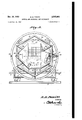
- Figure 3 is a front elevational view of one of the frames, illustrating a ⁇ car as positioned therein.
- Figure 4 is an enlarged end elevational View of a car and its supporting frames, the tracks and loading platform, being shown in section.
- the device comprises a main circular track 5 and an inner circular track 6, the circular tracks being concentric, the track 6 being somewhat elevated above the track 5.
- These tracks 5 and 6 are supported on the bars 1, which bars also support the uprights 8 and 9 on which the circular platform I0 is mounted, the circular platform i0 being provided with a guard rail ⁇ II at the rear thereof.
- the reference character I2 indicates the centrally disposed supporting post from which the arms I3 radiate, the arms diverging towards their outer ends, where they are connected with the outer frames of the car supports, the outer frames being indicated by the reference character I4.
- the outer frame of each car is substantially rectangular in formation, andr comprises vertical side members I5 and a horizontal member I6, there being provided supporting wheels il' which are mounted in the bearing plates I8 and which operate over the main circular track 5.
- the upper ends of the vertical members I9 are connected by the horizontal bar 22 which is provided with a bearing 23 disposed intermediate the ends thereof.
- This bearing 23 accommodates the shaft 24 which is hollow, and which supports the wheel 25, the wheel 25 being substantially large, for purposes to be hereinafter more fully described.
- the reference character 26 indicates a clutch means of the hydraulic construction, commonly used in motor vehicle structure, whereby the wheel 25 may either run free, or be clutched t0 the shaft 24, to cause the shaft 24 to rotate.
- an auxiliary frame made up of the tubes 2l, their ends being connected providing a frame of hexagonal construction, the frame also including rearwardly extended tubular sections 28 that connect with the tubes 21, at the adjacent ends thereof, the rear ends of the tubular sections 23 being connected by tubular sections 29 that cross each other, and to which the shaft 24 is connected, so that rotary movement of the shaft 24 may be transmitted to the inner frame to rotate the car, mounted therein.
- the cars which are indicated generally by the reference character 32 may be of any desired shape, the front and rear ends thereof preferably tapering as shown by Figure 3 of the drawings.
- Shafts 33 and 34 extend from the ends of the cars, and operate in bearings provided in certain of the tubes Z7 making up the inner frames of the device. Under normal conditions, these cars swing on their shafts due to centrifugal force, as the cars are moving over the track 5.
- Each car is provided with a seat such as indicated at 35, the seats of the cars being so disposed that the weight of the occupant seated thereon, will be below the center of gravity of the car, to normally hold the car against rolling.
- a strap 36 is provided as a part of each seat, so that the occupant ci the car may be strapped in the seat.
- Each car is provided with a door 'l which is so disposed that when open, the cars may be loaded from the sides, and from the plat forms, with facility.
- a pedal 3% which is adapted to operate the plunger 39 ci the iluid brake operating, which includes a reservoir le connected with the usual clutch cylinders, through the pipes 4l and 42, so that by operating the foot pedal, fluid pressure may be applied to clutch the inner frames in which the cars are mounted, to the wheels to cause the inner frames and cars mounted therein to take an end over end movement.
- this end over end movement may be slow or fast, depending on the speed of rotation of the device.
- a concentric driving ring 43 which is engaged by the friction wheel dfi of the power device 45, the power device being of any desired construction capable of rotating the friction wheel @l to rotate the arms and cars supported thereby.
- each car is provided with keeper openings f'l adapted to receive the sliding bolt l5 of the latch associated therewith, the sliding bolt 36 operating in openings formed in the lugs ill, between which the coiled spring i8 is mounted.
- the sliding bolt At one end oi the sliding bolt is a cam lever i9 which when swung inwardly, will operate to retract the sliding bolt, releasing the car, but when the cam lever 49 is swung to the position as shown by Figure 2 of the drawings, the sliding colt will project into the keeper opening of the car securing it against movement.
- a spring clip 50 is provided for each cam lever, to hold the cam levers of the cars in their active positions when set to prevent movement of the cars on their shafts ⁇
- the cars are rotated by the rotation of the concentric driving ring i3 which is attached to the arms i3.
- the occupant of the car may, by moving the pedal 33, clutch the inner frame of the device to the wheel 25 which forms a part of that particular car. Bly the occupant moving the pedal, the car may be thrown into and out of operation and the loop the loop movement as well as a rolling movement controlled at the will of the operator, providing an exceptionally spectacular and exciting ride for the occupants of the cars.
- a central support In a pleasure railway, outer and inner concentric tracks, a central support, arms radiating from the support, said arms extending to the outer track, main car frames movable on the outer track, a vertical circular track mounted on each car frame, inner car frames rotatable over the vertical tracks of the main car frames, horizontal shafts connected to the inner car frames, wheels operating over the inner track and mounted on the inner ends of the shafts, means for clutching the wheels to their shafts rotating the inner car frames end over end within the main car frame, cars mounted for rolling movement in a plane at right angles to the direction of travel of the car frames, and means for moving the car frames over the outer track.
- a central support arms radiating from the support, main car frames mounted for movement over the outer track, means for moving the main car frames over the outer track, inner car frames mounted for rotary movement in a vertical plane, disposed within the main car frames, horizontal shafts extending from the inner car frames, wheels mounted on the horizontal shafts, said wheels moving over the inner track, cars mounted for pivotal movement within the inner car frames, and occupant-controlled clutch means for connecting the wheels and the shafts, rotating the inner car frames end over end within the main car frames.
- an outer circular track and an inner circular track including horizontal bars, to which the circular tracks are connected, a central support, arms radiating from the support, main car frames mounted for movement over the tracks, and connected with the arms at the free ends thereof, said main car frames including inner vertical circular tracks, inner car frames mounted lor end over end rotary movement within the main car frames, cars pivotally mounted within the inner car frames and rotatable on horizontal axes, a wheel connected with each inner car frame and movable over the inner circular track, means for clutching the cars to the Wheels whereby said cars are rotated end over end in the direction of travel of the frames, and means for moving the frames over the circular tracks.
- a main circular track an inner track concentric to the main track, main car frames movable over the circular tracks, each of said car frames including a vertical circular track, inner car frames mounted within the lirst mentioned car frames and having wheels movable over theY vertical circular tracks of said main frames, cars mounted within the inner car frames, horizontal shafts extending from the inner car frames, wheels operating in vertical planes mounted on the shafts, occupant controlled means for clutching the wheels to their shafts, rotating the cars end over end, and means for moving the rst mentioned car frames over the circular tracks.
Description
Dec. 26, 1950 B. B. Pl-:wlTT 2,535,862?
VERTICAL AND HORIZONTAL AxEs RoUNnABouT Filed June 12', 1947 V4 sheets-sheet. 2
Pezvi l INVEN'FOR BY j l r Il n ATTORNEYS a Dec. 26, 1950 B. B. PEwlT'r 2,535,862
VERTICAL AND HORIZONTAL AXES ROUNDABOUT Filed June 12, 1947 4 Sheets-Sheet 3 EXBhPezvz/ INVENTOR BY l/ 1 l, 1
ATTORNEYS,
De@ 26, 1 950 B. B. PEwlT'r I 2,535,862
VERTICL AND HORIZONTAL AXES ROUNDABOUT Filed June l12, 1947 4 sheets-sheet 4 tfewt INVENTGH BY Mauri-0.
ATTORNEYS.
Patented Dec. 26, 1950 VERTICAL AND HORIZONTAL AXES ROUNDABOUT Bernard B. Pewitt, Chattanooga, Tenn.
Application June 12, 1947, Serial No. 754,168
4 Claims.
This invention relates to amusement devices, and more particularly to amusement devices embodying pleasure railways, an important object of the invention being to provide a pleasure railway including cars movable over a circular track, the cars being so supported and constructed that they may take a looping and rolling motion, the mechanism operating the cars for the looping and rolling motion, being controlled by the occupants of the cars, at the will of the occupants.
Another object of the invention is to provide a circular track and a plurality of arms radiating from a common center, operating within the circular track, there being provided oars mounted on the outer ends of the arms, so arranged that they will move over the track, means being provided for rotating the cars as they move over the circular track in what might be termed a looping motion.
Still another object of the invention is to prvide a pleasure railway of this character wherein the cars may be loaded from the sides, permitting the loading of the cars with facility.
Still another object of the invention is to mount the seats of the cars so that the center of gravity of the weight of the occupants in the seats, will be below the horizontal axes of the cars, whereby the cars are caused to `roll on the horizontal axes under the weight of the occupants of the cars, as the mechanical ymeans for causing the looping action is thrown into operation, by the occupants of the cars.
With the foregoing and other objects in view which will appear as the description proceeds, the invention consists of certain novel details of construction and combinations of parts, hereinafter more fully described and pointed out in the claims, it being understood that changes may be made in the construction and arrangement of parts without departing from the spirit of the invention as claimed.
Referring to the drawings Figure 1 is a plan view of a pleasure railway, constructed in accordance with the invention.
Figure 2 is an enlarged plan View of one of the cars of the railway, illustrating the supporting frames for the cars.
Figure 3 is a front elevational view of one of the frames, illustrating a `car as positioned therein.
Figure 4 is an enlarged end elevational View of a car and its suporting frames, the tracks and loading platform, being shown in section.
Referring to the drawings in detail, the device comprises a main circular track 5 and an inner circular track 6, the circular tracks being concentric, the track 6 being somewhat elevated above the track 5. These tracks 5 and 6 are supported on the bars 1, which bars also support the uprights 8 and 9 on which the circular platform I0 is mounted, the circular platform i0 being provided with a guard rail` II at the rear thereof.
The reference character I2 indicates the centrally disposed supporting post from which the arms I3 radiate, the arms diverging towards their outer ends, where they are connected with the outer frames of the car supports, the outer frames being indicated by the reference character I4. The outer frame of each car :is substantially rectangular in formation, andr comprises vertical side members I5 and a horizontal member I6, there being provided supporting wheels il' which are mounted in the bearing plates I8 and which operate over the main circular track 5.
The rear ends 0f the side members I5, connect with the vertical members IQ which in turn are connected at their upper ends, to the horizontal bars 2Q that extend forwardly and connect with the circular track member 2l that is `disposed vertically, as clearly shown by Figures 2 and 3 of the drawings.
The upper ends of the vertical members I9 are connected by the horizontal bar 22 which is provided with a bearing 23 disposed intermediate the ends thereof. This bearing 23 accommodates the shaft 24 which is hollow, and which supports the wheel 25, the wheel 25 being substantially large, for purposes to be hereinafter more fully described.
The reference character 26 indicates a clutch means of the hydraulic construction, commonly used in motor vehicle structure, whereby the wheel 25 may either run free, or be clutched t0 the shaft 24, to cause the shaft 24 to rotate.
Within the outer frame, and operating within the circular track member 2i, is an auxiliary frame made up of the tubes 2l, their ends being connected providing a frame of hexagonal construction, the frame also including rearwardly extended tubular sections 28 that connect with the tubes 21, at the adjacent ends thereof, the rear ends of the tubular sections 23 being connected by tubular sections 29 that cross each other, and to which the shaft 24 is connected, so that rotary movement of the shaft 24 may be transmitted to the inner frame to rotate the car, mounted therein.
Connected to certain of the tubes 2l, as shown by Figure 3 of the drawings, are spaced plates 3c between which the wheels 3l operate, the wheels 3| moving over the circular track member 2I, when the shaft 2li rotates to rotate the inner frame. i
The cars which are indicated generally by the reference character 32 may be of any desired shape, the front and rear ends thereof preferably tapering as shown by Figure 3 of the drawings. Shafts 33 and 34 extend from the ends of the cars, and operate in bearings provided in certain of the tubes Z7 making up the inner frames of the device. Under normal conditions, these cars swing on their shafts due to centrifugal force, as the cars are moving over the track 5.
Each car is provided with a seat such as indicated at 35, the seats of the cars being so disposed that the weight of the occupant seated thereon, will be below the center of gravity of the car, to normally hold the car against rolling. A strap 36 is provided as a part of each seat, so that the occupant ci the car may be strapped in the seat. Each car is provided with a door 'l which is so disposed that when open, the cars may be loaded from the sides, and from the plat forms, with facility.
Within each car, in easy access to the occupant of the car, is a pedal 3% which is adapted to operate the plunger 39 ci the iluid brake operating, which includes a reservoir le connected with the usual clutch cylinders, through the pipes 4l and 42, so that by operating the foot pedal, fluid pressure may be applied to clutch the inner frames in which the cars are mounted, to the wheels to cause the inner frames and cars mounted therein to take an end over end movement. In View of the diameters of the `'wheels 25, it will be seen that this end over end movement may be slow or fast, depending on the speed of rotation of the device.
Connected with the arms i3, is a concentric driving ring 43 which is engaged by the friction wheel dfi of the power device 45, the power device being of any desired construction capable of rotating the friction wheel @l to rotate the arms and cars supported thereby.
In order that the cars may be secured against swinging movement during the loading thereof, each car is provided with keeper openings f'l adapted to receive the sliding bolt l5 of the latch associated therewith, the sliding bolt 36 operating in openings formed in the lugs ill, between which the coiled spring i8 is mounted. At one end oi the sliding bolt is a cam lever i9 which when swung inwardly, will operate to retract the sliding bolt, releasing the car, but when the cam lever 49 is swung to the position as shown by Figure 2 of the drawings, the sliding colt will project into the keeper opening of the car securing it against movement. A spring clip 50 is provided for each cam lever, to hold the cam levers of the cars in their active positions when set to prevent movement of the cars on their shafts` In the operation of the pleasure railway or amusement device, the cars are rotated by the rotation of the concentric driving ring i3 which is attached to the arms i3.
As the cars rotate or move over the track 5, the occupant of the car may, by moving the pedal 33, clutch the inner frame of the device to the wheel 25 which forms a part of that particular car. Bly the occupant moving the pedal, the car may be thrown into and out of operation and the loop the loop movement as well as a rolling movement controlled at the will of the operator, providing an exceptionally fascinating and exciting ride for the occupants of the cars.
What is claimed is:
1. In a pleasure railway, outer and inner concentric tracks, a central support, arms radiating from the support, said arms extending to the outer track, main car frames movable on the outer track, a vertical circular track mounted on each car frame, inner car frames rotatable over the vertical tracks of the main car frames, horizontal shafts connected to the inner car frames, wheels operating over the inner track and mounted on the inner ends of the shafts, means for clutching the wheels to their shafts rotating the inner car frames end over end within the main car frame, cars mounted for rolling movement in a plane at right angles to the direction of travel of the car frames, and means for moving the car frames over the outer track.
2. In a pleasure railway, outer and inner concentric tracks, a central support, arms radiating from the support, main car frames mounted for movement over the outer track, means for moving the main car frames over the outer track, inner car frames mounted for rotary movement in a vertical plane, disposed within the main car frames, horizontal shafts extending from the inner car frames, wheels mounted on the horizontal shafts, said wheels moving over the inner track, cars mounted for pivotal movement within the inner car frames, and occupant-controlled clutch means for connecting the wheels and the shafts, rotating the inner car frames end over end within the main car frames.
3. In a pleasure railway, an outer circular track and an inner circular track, including horizontal bars, to which the circular tracks are connected, a central support, arms radiating from the support, main car frames mounted for movement over the tracks, and connected with the arms at the free ends thereof, said main car frames including inner vertical circular tracks, inner car frames mounted lor end over end rotary movement within the main car frames, cars pivotally mounted within the inner car frames and rotatable on horizontal axes, a wheel connected with each inner car frame and movable over the inner circular track, means for clutching the cars to the Wheels whereby said cars are rotated end over end in the direction of travel of the frames, and means for moving the frames over the circular tracks.
4. In a pleasure railway, a main circular track, an inner track concentric to the main track, main car frames movable over the circular tracks, each of said car frames including a vertical circular track, inner car frames mounted within the lirst mentioned car frames and having wheels movable over theY vertical circular tracks of said main frames, cars mounted within the inner car frames, horizontal shafts extending from the inner car frames, wheels operating in vertical planes mounted on the shafts, occupant controlled means for clutching the wheels to their shafts, rotating the cars end over end, and means for moving the rst mentioned car frames over the circular tracks.
BERNARD B. PEWI'IT.
REFERENCES CITED The following references are of record inthe Jfile of this patent:
vEyerly -c July 7, 1935
Priority Applications (1)
| Application Number | Priority Date | Filing Date | Title |
|---|---|---|---|
| US754168A US2535862A (en) | 1947-06-12 | 1947-06-12 | Vertical and horizontal axes roundabout |
Applications Claiming Priority (1)
| Application Number | Priority Date | Filing Date | Title |
|---|---|---|---|
| US754168A US2535862A (en) | 1947-06-12 | 1947-06-12 | Vertical and horizontal axes roundabout |
Publications (1)
| Publication Number | Publication Date |
|---|---|
| US2535862A true US2535862A (en) | 1950-12-26 |
Family
ID=25033710
Family Applications (1)
| Application Number | Title | Priority Date | Filing Date |
|---|---|---|---|
| US754168A Expired - Lifetime US2535862A (en) | 1947-06-12 | 1947-06-12 | Vertical and horizontal axes roundabout |
Country Status (1)
| Country | Link |
|---|---|
| US (1) | US2535862A (en) |
Cited By (18)
| Publication number | Priority date | Publication date | Assignee | Title |
|---|---|---|---|---|
| US2689126A (en) * | 1950-07-26 | 1954-09-14 | Lee U Eyerly | Gear-driven control for ferris wheel cars |
| US3041741A (en) * | 1960-03-16 | 1962-07-03 | Jr Charles L Barker | Space flight simulator |
| US3136075A (en) * | 1962-02-23 | 1964-06-09 | Republic Aviat Corp | Articulated centrifuge |
| US4775144A (en) * | 1986-02-02 | 1988-10-04 | Paul Shipman | Rotatable and vertically oscillatable passenger amusement assembly |
| US5791254A (en) * | 1995-11-03 | 1998-08-11 | Meteoro Amusement Corporation | Full range of motion roller coaster |
| US6095926A (en) * | 1998-05-01 | 2000-08-01 | Universal Studios, Inc. | Amusement ride vehicle |
| US6098549A (en) * | 1996-11-01 | 2000-08-08 | Meteoro Corporation | Modularized amusement ride and training simulation device |
| US6227121B1 (en) | 1995-11-03 | 2001-05-08 | Metero Amusement Corporation | Modularized amusement ride and training simulation device |
| US6402624B1 (en) | 1998-11-18 | 2002-06-11 | Versa Corporation | Amusement ride without hubs and spokes |
| US6523479B1 (en) | 2001-09-06 | 2003-02-25 | S&S-Arrow, Llc | Amusement rides and methods |
| WO2003082421A2 (en) * | 2002-03-22 | 2003-10-09 | Threlkel David V | Amusement ride |
| US20070010336A1 (en) * | 2005-05-20 | 2007-01-11 | Kitchen William J | Wheel Hub Rider Conveyance |
| US20080113822A1 (en) * | 2006-11-14 | 2008-05-15 | William J. Kitchen | Big Wheel Roundabout Amusement Ride |
| US7610859B1 (en) | 2007-06-30 | 2009-11-03 | Jordan Reder Dietrich | Carriage rotatable roller coaster tracks and vehicles |
| US20090320712A1 (en) * | 2006-05-26 | 2009-12-31 | Macmahon Patrick | Amusement ride |
| US8096892B2 (en) | 2002-03-25 | 2012-01-17 | Water Ride Concepts, Inc. | Control system for water amusement devices |
| US8641542B2 (en) | 2009-09-04 | 2014-02-04 | William J. Kitchen | Stationary track with gimbaled rider carriages amusement ride |
| US11517828B2 (en) | 2019-06-19 | 2022-12-06 | Universal City Studios Llc | Choreographed ride systems and methods |
Citations (4)
| Publication number | Priority date | Publication date | Assignee | Title |
|---|---|---|---|---|
| US678670A (en) * | 1901-03-08 | 1901-07-16 | Peter M Kling | Railroad ferris wheel. |
| US942230A (en) * | 1909-03-31 | 1909-12-07 | Arthur T Prescott | Amusement apparatus. |
| US1502484A (en) * | 1922-02-11 | 1924-07-22 | Oscar F Olson | Roundabout |
| US2046678A (en) * | 1935-02-19 | 1936-07-07 | Lee U Eyerly | Airplane amusement device |
-
1947
- 1947-06-12 US US754168A patent/US2535862A/en not_active Expired - Lifetime
Patent Citations (4)
| Publication number | Priority date | Publication date | Assignee | Title |
|---|---|---|---|---|
| US678670A (en) * | 1901-03-08 | 1901-07-16 | Peter M Kling | Railroad ferris wheel. |
| US942230A (en) * | 1909-03-31 | 1909-12-07 | Arthur T Prescott | Amusement apparatus. |
| US1502484A (en) * | 1922-02-11 | 1924-07-22 | Oscar F Olson | Roundabout |
| US2046678A (en) * | 1935-02-19 | 1936-07-07 | Lee U Eyerly | Airplane amusement device |
Cited By (26)
| Publication number | Priority date | Publication date | Assignee | Title |
|---|---|---|---|---|
| US2689126A (en) * | 1950-07-26 | 1954-09-14 | Lee U Eyerly | Gear-driven control for ferris wheel cars |
| US3041741A (en) * | 1960-03-16 | 1962-07-03 | Jr Charles L Barker | Space flight simulator |
| US3136075A (en) * | 1962-02-23 | 1964-06-09 | Republic Aviat Corp | Articulated centrifuge |
| US4775144A (en) * | 1986-02-02 | 1988-10-04 | Paul Shipman | Rotatable and vertically oscillatable passenger amusement assembly |
| US5791254A (en) * | 1995-11-03 | 1998-08-11 | Meteoro Amusement Corporation | Full range of motion roller coaster |
| US6227121B1 (en) | 1995-11-03 | 2001-05-08 | Metero Amusement Corporation | Modularized amusement ride and training simulation device |
| US6386115B2 (en) | 1995-11-03 | 2002-05-14 | Meteoro Amusement Corporation | Modularized amusement ride and training simulation device |
| US6098549A (en) * | 1996-11-01 | 2000-08-08 | Meteoro Corporation | Modularized amusement ride and training simulation device |
| US6095926A (en) * | 1998-05-01 | 2000-08-01 | Universal Studios, Inc. | Amusement ride vehicle |
| US6402624B1 (en) | 1998-11-18 | 2002-06-11 | Versa Corporation | Amusement ride without hubs and spokes |
| US6523479B1 (en) | 2001-09-06 | 2003-02-25 | S&S-Arrow, Llc | Amusement rides and methods |
| WO2003082421A3 (en) * | 2002-03-22 | 2004-01-08 | David V Threlkel | Amusement ride |
| WO2003082421A2 (en) * | 2002-03-22 | 2003-10-09 | Threlkel David V | Amusement ride |
| US8066576B2 (en) | 2002-03-22 | 2011-11-29 | Threlkel David V | Amusement ride |
| US8096892B2 (en) | 2002-03-25 | 2012-01-17 | Water Ride Concepts, Inc. | Control system for water amusement devices |
| US20070010336A1 (en) * | 2005-05-20 | 2007-01-11 | Kitchen William J | Wheel Hub Rider Conveyance |
| US7594473B2 (en) | 2005-05-20 | 2009-09-29 | William J. Kitchen | Wheel hub rider conveyance |
| US20090320712A1 (en) * | 2006-05-26 | 2009-12-31 | Macmahon Patrick | Amusement ride |
| US8683923B2 (en) * | 2006-05-26 | 2014-04-01 | Patrick Charles David Macmahon | Amusement ride |
| US7918740B2 (en) * | 2006-11-14 | 2011-04-05 | William J. Kitchen | Big wheel roundabout amusement ride |
| WO2008061050A1 (en) * | 2006-11-14 | 2008-05-22 | Kitchen Wiliam J | Big wheel roundabout amusement ride |
| US20080113822A1 (en) * | 2006-11-14 | 2008-05-15 | William J. Kitchen | Big Wheel Roundabout Amusement Ride |
| US7610859B1 (en) | 2007-06-30 | 2009-11-03 | Jordan Reder Dietrich | Carriage rotatable roller coaster tracks and vehicles |
| US8641542B2 (en) | 2009-09-04 | 2014-02-04 | William J. Kitchen | Stationary track with gimbaled rider carriages amusement ride |
| US11517828B2 (en) | 2019-06-19 | 2022-12-06 | Universal City Studios Llc | Choreographed ride systems and methods |
| US11918925B2 (en) | 2019-06-19 | 2024-03-05 | Universal City Studios Llc | Choreographed ride systems and methods |
Similar Documents
| Publication | Publication Date | Title |
|---|---|---|
| US2535862A (en) | Vertical and horizontal axes roundabout | |
| US2294166A (en) | Amusement device | |
| US2547152A (en) | Multiplane rotating movement for aerial amusement rides | |
| US1422032A (en) | Amusement device | |
| US2498450A (en) | Pleasure railway | |
| US2828128A (en) | Amusement ride device | |
| US657166A (en) | Elevated trolley-way. | |
| US3885788A (en) | Jump-over amusement ride | |
| US2280643A (en) | Amusement apparatus | |
| US928435A (en) | Elevated suspended-track automotor-railway. | |
| US2058279A (en) | Amusement device | |
| US2546917A (en) | Vertical axis roundabout | |
| US2397857A (en) | Amusement device | |
| US1068852A (en) | Aero merry-go-round. | |
| US2017099A (en) | Amusement device | |
| US2274956A (en) | Operating mechanism for amusement devices | |
| US2513607A (en) | Merry-go-round | |
| US1334727A (en) | Pleasure-machine | |
| US1640038A (en) | Passenger car for amusement rides | |
| US2629593A (en) | Occupant carrying roundabout | |
| US1674886A (en) | Merry-go-round | |
| US937212A (en) | Braking mechanism for automobiles. | |
| US1881646A (en) | Merry-go-round | |
| US393709A (en) | Aloys maria leinwathee | |
| US1065783A (en) | Roundabout. |