US1852574A - Switch machine for railroads - Google Patents
Switch machine for railroads Download PDFInfo
- Publication number
- US1852574A US1852574A US399547A US39954729A US1852574A US 1852574 A US1852574 A US 1852574A US 399547 A US399547 A US 399547A US 39954729 A US39954729 A US 39954729A US 1852574 A US1852574 A US 1852574A
- Authority
- US
- United States
- Prior art keywords
- brake
- motor
- armature
- switch
- switch machine
- Prior art date
- Legal status (The legal status is an assumption and is not a legal conclusion. Google has not performed a legal analysis and makes no representation as to the accuracy of the status listed.)
- Expired - Lifetime
Links
Images

Classifications
-
- B—PERFORMING OPERATIONS; TRANSPORTING
- B61—RAILWAYS
- B61L—GUIDING RAILWAY TRAFFIC; ENSURING THE SAFETY OF RAILWAY TRAFFIC
- B61L5/00—Local operating mechanisms for points or track-mounted scotch-blocks; Visible or audible signals; Local operating mechanisms for visible or audible signals
- B61L5/06—Electric devices for operating points or scotch-blocks, e.g. using electromotive driving means
- B61L5/065—Construction of driving mechanism
Definitions
- This invention relates to switch machines for railroad track switches, and more particularly pertains to an electro-magnetic brake for use with such switch machines.
- Such a brake accomplishes this function particularly well in the case of switch machine control circuits whichv provide a shunt, or safety circuit, for the shunting out of the unauthorized energy from the next active opera-ting control wlre, in a manner such for example, as shown in my patent No. 1,824,146 dated September 22, 1931, as the shunt circuit prevents the unauthorized energy from attaining a normal operating value.
- the present invention proposes to provide an electro-magnetic brake particularly adaptable to switch machines and provided with means for normally biasing it to a braking condi tion; with electro-magnetic means for releasing said brake; and with means for manually releasing said brake.
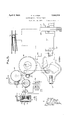
- Fig. l is a side elevation of an electromagnetic brake constructed according to the resent invention with certain parts shown in section;
- Fig. 2 is a sectional view taken on line 2-2 of Fig. 1, showing the manual releasing means provided according to the present invention
- Fig. 3 is a sectional view taken on line 33 of Fig. 1;
- Fig. 4. is a sectional view taken on line l& of F 3 showing the brake adjusting means
- Fig. 5 is a diagrammatic representation of a switch machine and its associated track switch with the electromagnetic brake of the present invention shown as applied to the switch machine motor.
- an electro-magnetic brake BR is shown as suitably attached to a motor M of a switch machine, of which a motor frame member 5 is fragmentarily shown with its associated armature 6.
- the brake BB in cludes a cup-shaped frame member 7 which is suitably secured to the motor frame member 5 and serves as a bearing support for the armature 6.
- This is accomplished by providing a ball bearing unit 8 which suitably rides on a bearing bushing 9 that is pressed over a shaft 10 of the switch machine motor armature 6.
- his ball bearing unit 8 is secured in position by the threading of a core
- This core member '11 serves for securing a suitable energizing coil 12 and extends to a point flush with the rim of frame member 7.
- Coacting with the core member 11 and coil 12 is an armature 13 which is biasedby a s ring 14 mounted within the core member 11.
- armature 131's prevented from rotational movement by pins 16 which are suitably secured to the armature 13 and provided for slidably' engaging the frame member 7 (see Fig. 4).
- the armature 13 is cadmium plated on the side which comes into contact with the core member 11 when the coil 12 is energized. This causes residual magnetism to be ineffective to cause the armature 13 to stick in anenergizedposition.
- a brake housing 18 is adjnstably secured to the frame member 7 by bolts 19 (see Fig. 4). Between the housing member 18 and the frame member 7 are shims 25 of varying thickness which provide means for adjusting the position of the housing member 18 in respect to said frame member 7. Such adjusting means is provided at a plurality of points around the outer edge of the housing member 18 and frame member 7, one such point being shown in Fig. 3.
- a rotating disc member 20 has secured thereto on two sides brake linings 21 and 22 which are between a braking surface 18 and the surface of the armature 13.
- This disc member 20 is suitably welded to a broached bushing 23 which slidably engages the shaft 10 of the switch machine motor M in a manner so that if the shaft 10 rotates, the disc 20 is also caused to rotate (see Fig. 3).
- the reluctance of the magnetic circuit for the magnetism produced by the coil 12 is considerably reduced so that the current required to hold the armature 13 in a released position is considerably less than that current which is required to attract the armature to such a position.
- the characteristics of the brake BR may be adjusted so that it will be necessary for a current to flow in the coil 12 corresponding to the current flow in the motor for normal starting purposes in order to release the brake, while the brake is maintained released by a reduced current value which is in correspondence with the reduced operating current of the switch machine motor. It will be noted, that this value of current for releasing the brake may be varied by changing the normal air gap between the armature 13 and the core member 11, for which.
- the adjustable mounting means including the shims 25. More specifically, the removal of a particular size of shim 25 at each of the points of. support,.moves the braking surface 18 to a certain position nearer the core member 11, thus causing the armature 13 to alsobe moved nearer the core member 11.
- a shaft is vertically supported in the brake housing 18 and is provided with flattened portions 30 and 30" which engage pins 31 and 32 respectively that are fixed to the armature 13.
- the shaft 30 is partially rotated, the armature 13 is forced against the bias of spring 14.
- a hand crank 33 which may be non-rotatably secured to the shaft 30 (see Figs. 2 and 5).
- a manual releasing means for the brake BB is provided.
- acover 34 is caused to assume a position over the shaft 30 by a spring 35.
- .A. cover 36 is suitably secured in position over the armature 6 of the motor M.
- the space thus inclosed also includes a projection 7 which serves to mount an insulated block 37 secured by a bolt 38 for holding the necessary lead wires of the brake BR and motor M in a suitable position.
- a track switch TS controlled by any suitable switch. machine such as set forth in my Patent No- 1,466,903 dated September 4, 1923 with the brake BR, as the specific embodiment of the present invention associated with the motor M of the switch machine.
- my Patent No- 1,466,903 dated September 4, 1923 with the brake BR as the specific embodiment of the present invention associated with the motor M of the switch machine.
- the motor M may be controlled in any well known manner, for example, as set forth in my Patent No. 1,550,611 dated August 18,
- the torque produced by the motor M during operation is transmitted from a pinion 41 to a bevel gear 42 with which it meshes.
- This bevel gear 42 is connected with a pinion 43 in which the crank 40 may be suitably inserted at such times that it is desirable to manually operate the switch machine.
- This pinion 43 engages a gear 44 which is con nected to a pinion 45, that in turn drives the main drive gear 46.
- the main drive gear 46 When the lock dogs LD and LD have disengaged their respective locking members, the main drive gear 46 operates the throw bar TB to an extreme position which movement also operates the lock rods LE and LR to a corresponding extreme position, after which the main drive gear 46 continues rotation in the same direction to move the lock plunger LP to a position in which the lock dogs Ll) and LD again look their respective locking members.
- the motor M can only operate the track switch through the switch machine at such times that said track switch is unlocked
- any force applied to the track switch points only tends to operate the motor M at such times that the track switch is unlocked.
- the provision of the brake BR permits the motor M to operate the track switch TS and prevents said track switch TS from operating the motor M at such times that the track switch TS is unlocked, which results in the track switch being prevented from movement at all times except when power either manual or electrical is properly applied to the switch machine.
- this electro-magnetic brake may be varied over a wide range by changing the characteristics, that is, the number of turns on the coil; the number of coils and their respective connections; and by changing the air gap between the core and the armature; or other means of modifying the magnetic circuit of the brake.
- An example of such modified characteristics and the use of such a brake having two energizing coils is set forth in detail in my Patent No. 1,794,620 dated March 3, 1931. It is also obvious that the brake BR may be included in various types of operating circuits several of which have been heretofore mentioned.
- an electromagnetic brake has been shown and described as preventing the movement of a switch machine except when such brake is energized with a value of current sufficient to normally operate the switch machine.
- This brake has also been provided with manually' operable releasing means.
- Such a brake has many applications and may be used with other mechanisms than with a switch machine, such for instance, as used with a car retarder mechanism or the like, or in other such case where there is a driven element and a driving element.
- an electric'motor In combination with power driven, and manually operable, trailic regulating devices for railroads, an electric'motor, a driven element, driven by the motor, a spring biased brake preventing movement of said driven element exce t when actuated, electro-magnetic means or actuating said brake to a released condition when a normal value of operating' power is delivered to said motor, and manual means for actuating said brake to a released condition.
- an electric motor In combination with power driven, and hand operable, traflic regulating devices for railroads, an electric motor, a driven element, driven by the motor, a disc attached to said driven element, a fixed member, a movable member, a coil spring compressing said movable member against said fixed member with said disc between said fixed and said movable members, electro-magnetic means for releasing pressure upon said disc, and manual means for releasing pressure upon said disc.
- an electric motor for use with power driven, and hand operable, traflic regulating devices for railroads, an electric motor, a driven element, driven by said motor, a disc rotatable with said driven element and slidably attached thereto, a fixed brakingmember on one side of said disc, a non-rotating slidable armatlrremember' on the opposite side of said disc, a coil spring biasing said slidable armature member against said disc in a manner so that rotation of said disc is prevented, an electromagnetic structure active when energized for releasing the pressure of said slidable armature member against said disc, operated means on said slidable armature memb r, and a shaft engageable with said two means to release pressure against said disc when said shaft is operated.
- a normally active brake preventing movement of said switch: machine at all times except when actuated, electro-magnetic means for actuating said brake to as released condition, and manual means for actuating said brake to a released condition.
- a disc brake spring'biased to braking condition In combination with a track switch for railroads and a power driven, and hand operable, switch machine for such switch, a disc brake spring'biased to braking condition, an electromagnetic releasing structure including, a single core structure and means for actively magnetizing said core, and a manual releasing means for the brake.
- an electric niotor In combination with a track switch for railroads and a power, and manually, driven switch machine for such switch, an electric niotor, an electro-mechanical brake normaL 1y preventing rotation of said motor except when energized, said brake including, a disc slidably attached to the armature shaft of said motor and rotatable therewith, a fixed braking member on one side of said disc, a non-rotating slidable braking member on the opposite side of said disc, a coil spring mounted over said armature shaft and forcing said slidable braking member against said fixed braking member with said disc positioned between said slidable braking member and said fixed braking member, a core member mounted around said coil spring and said shaft and capable, when energized, of releasing the spring pressure against said disc, energizing means for said core, pins located substantially diametrically opposite on said slidable brake member, and a manually op erablc shaft slidably engaging said pins in
- an electric motor a disc slidably attached to the shaft of said motor and rotatable thereby, a fixed braking membcr located on one side of said disc, a coil spring mounted over said motor shaft, 8.
- movable armature member biased by said coil spring to force said disc against said fixed braking member, a core member for attracting said armature member, energizing means for said core member, means for adjusting the distance between said core member and said movable armature member, and means for manually preventing said coil spring from forcing said disc against said braking member.
- an electric motor a braking member attached to the shaft of said motor and rotated thereby, a fixed braking member, biasing means normally causing said braking member to slidably engage said fixed braking member to thereby prevent rotation of said motor, electro-mag'netic means for releasing said braking member from said fixed braking member and controlled by the power current of said motor, adjusting means for determining the amount of current necessary to release said brakin member, and manual means for releasing sai braking member.
- electro-Inagneti'c means including, a cup-shaped structure having an inner core member, energizing means for said core member, and an armature operably controlled by said core member and said energizing means, for releasing said braking member from said fixed braking member; and adjusting means for determining the normal released air gap between said core member and said armature.
- an electric motor a braking member attached to the shaft of said motor and rotated thereby, a fixed braking member, an annular Winding, a cup-shaped magnetic structure enclosing said winding, a core member extending from the base of said cup through said winding to a plane on the level with the rim of said cup-shaped structure, an armature enclosing said cupshaped structure, biasing means normally forcing said armature away from said cupshaped structure to slidably engage said braking member and thereby cause said braking member to slidably engage said fixed braking member, means preventing rotation of said armature, means adjustably determining the de-energized distance of said armature from I said core member, means fixedly determining the energized distance of said armature from said core member, and manual means for causing said armature to assume an energized released position without energization of said Winding, whereby the rotation of said motor is normally prevented, and whereby the rotation of said motor is allowed either by ener
- an electric motor a drive shaft permanently connected to the motor, braking means for the motor biased to braking position, means for automatically releasing the braking means when the motor receives operating power, and separate manually operable release means for the braking means.
Description
April 5, 1932. w. K. HOWE SWITCH MACHINE FOR RAILROADS 2 Sheets-Sheet Filed Oct. 14, 1929 FIGQZ.
I April-5, I w, K, HOWE 1,852,574
SWITCH MACHINE FOR RAILROADS Filed Oct. 14-, 1929 2 Sheets-Sheet 2 .0 "Q a g m f L h/ N '4 E BY MM ATTORNEY Patented Apr. 5, 1932 UNITED STATES FATEPQ'T OFFICE WINTHROP K. HOWE, OF ROCHESTER, NEVJ YORK, ASSIGHOR TO GENERAL RAILWAY SIGNAL COMPANY, OF ROCE-ZESTER, N l FYI YORK SWITCH MACHINE F03 EAILRGADS Application filed October 1 1829.
This invention relates to switch machines for railroad track switches, and more particularly pertains to an electro-magnetic brake for use with such switch machines.
It is desirable to provide a switch machine with an electro-magnetic brake, which is controlled by the operating current of the switch machine motor, because of the safety which is provided in certain abnormal cases of operation.
In one such case, with the current required to release the brake equal to nearly full normal operating current of the switch machine motor, the track switch is prevented from. be-
ing unlocked or partially operated by the application of unauthorized power of a lesser value. Such a brake accomplishes this function particularly well in the case of switch machine control circuits whichv provide a shunt, or safety circuit, for the shunting out of the unauthorized energy from the next active opera-ting control wlre, in a manner such for example, as shown in my patent No. 1,824,146 dated September 22, 1931, as the shunt circuit prevents the unauthorized energy from attaining a normal operating value.
In another case, let us assume that the switch points are operated to the desired eX- treme position with the switch machine failing to lock the track switch, due to the opening of an over-load device, the failure of parts, or the like. This condition results in the display of a stop indication by the governing signal, but the tower operator, or, other ofiicial, desiring to expedite the movement-of traffic, orders a train to proceed under flag, that is, a flag-man is sent ahead of the train which then proceeds over the apparently locked switch points. This case is particularly dangerous where the train passing over the switch points in question is making a facing point move, as the vibration and Weaving of the track rails during the passage of the train may be suflicient to move the switch points away from a proper position, resulting in the engagement of car wheel flange and thus causing a split train. Such a case is amply provided for by the use of an electro-magnetic brake, in as much as any movement of the track switch points is Serial No. 399,547.
prevented by the brake even though said switch points are not locked in the normal manner.
It is desirable, for reasons well known to those skilled in the art, to provide switch machines with means for manual operation. Thus, in applying an electromagnetic brake which is controlled by the operating current of the switch machine motor, it also becomes necessary to provide manual means for releasing such a brake, so that the manual means provided for emergency operation of the switch machine shall still be effective.
lVith the above considerations in mind, the present invention proposes to provide an electro-magnetic brake particularly adaptable to switch machines and provided with means for normally biasing it to a braking condi tion; with electro-magnetic means for releasing said brake; and with means for manually releasing said brake.
Other objects, purposes and characteristic features will be in part obvious from the accon'ipanying drawings and in part pointed out as the description of the invention progresses.
in describing the invention in detail, reference will be made to the accompanying drawings in which like reference characters indicate corresponding parts in the several views, and which Fig. l is a side elevation of an electromagnetic brake constructed according to the resent invention with certain parts shown in section;
Fig. 2 is a sectional view taken on line 2-2 of Fig. 1, showing the manual releasing means provided according to the present invention;
Fig. 3 is a sectional view taken on line 33 of Fig. 1;
Fig. 4. is a sectional view taken on line l& of F 3 showing the brake adjusting means;
Fig. 5 is a diagrammatic representation of a switch machine and its associated track switch with the electromagnetic brake of the present invention shown as applied to the switch machine motor.
Vith reference to Fig. 1 of the accompanymember 11 into the frame member 7.
ing drawings, an electro-magnetic brake BR is shown as suitably attached to a motor M of a switch machine, of which a motor frame member 5 is fragmentarily shown with its associated armature 6. The brake BB in cludes a cup-shaped frame member 7 which is suitably secured to the motor frame member 5 and serves as a bearing support for the armature 6. This is accomplished by providing a ball bearing unit 8 which suitably rides on a bearing bushing 9 that is pressed over a shaft 10 of the switch machine motor armature 6. his ball bearing unit 8 is secured in position by the threading of a core This core member '11, as its name implies, serves for securing a suitable energizing coil 12 and extends to a point flush with the rim of frame member 7.
. Coacting with the core member 11 and coil 12 is an armature 13 which is biasedby a s ring 14 mounted within the core member 11.
he armature 131's prevented from rotational movement by pins 16 which are suitably secured to the armature 13 and provided for slidably' engaging the frame member 7 (see Fig. 4). The armature 13 is cadmium plated on the side which comes into contact with the core member 11 when the coil 12 is energized. This causes residual magnetism to be ineffective to cause the armature 13 to stick in anenergizedposition.
A brake housing 18 is adjnstably secured to the frame member 7 by bolts 19 (see Fig. 4). Between the housing member 18 and the frame member 7 are shims 25 of varying thickness which provide means for adjusting the position of the housing member 18 in respect to said frame member 7. Such adjusting means is provided at a plurality of points around the outer edge of the housing member 18 and frame member 7, one such point being shown in Fig. 3.
A rotating disc member 20 has secured thereto on two sides brake linings 21 and 22 which are between a braking surface 18 and the surface of the armature 13. This disc member 20 is suitably welded to a broached bushing 23 which slidably engages the shaft 10 of the switch machine motor M in a manner so that if the shaft 10 rotates, the disc 20 is also caused to rotate (see Fig. 3).
It is thus seen that, when the coil 12 is energized and the core member 11 becomes magnetized sufiiciently, the armature member 13 is attracted against the biasing effect of the coil spring 14 until it comes into contact with the core member 11 and the frame member 7. hen the armature 13 is thus attracted against the biasing effect of the spring 14, the pressure against the brake linings 21 and 22 is released which permits the disc 20 to revolve freely with the motor I armature 6.
lVhen the armature 13 is in an attracted position, the reluctance of the magnetic circuit for the magnetism produced by the coil 12 is considerably reduced so that the current required to hold the armature 13 in a released position is considerably less than that current which is required to attract the armature to such a position. In other words, the characteristics of the brake BR may be adjusted so that it will be necessary for a current to flow in the coil 12 corresponding to the current flow in the motor for normal starting purposes in order to release the brake, while the brake is maintained released by a reduced current value which is in correspondence with the reduced operating current of the switch machine motor. It will be noted, that this value of current for releasing the brake may be varied by changing the normal air gap between the armature 13 and the core member 11, for which. provision is made by the adjustable mounting means including the shims 25. More specifically, the removal of a particular size of shim 25 at each of the points of. support,.moves the braking surface 18 to a certain position nearer the core member 11, thus causing the armature 13 to alsobe moved nearer the core member 11.
A shaft is vertically supported in the brake housing 18 and is provided with flattened portions 30 and 30" which engage pins 31 and 32 respectively that are fixed to the armature 13. lVhen the shaft 30 is partially rotated, the armature 13 is forced against the bias of spring 14. Thus, by the provision of a hand crank 33, which may be non-rotatably secured to the shaft 30 (see Figs. 2 and 5)., a manual releasing means for the brake BB is provided. \Vhen the crank 33 is not in position, acover 34 is caused to assume a position over the shaft 30 by a spring 35.
.A. cover 36 is suitably secured in position over the armature 6 of the motor M. The space thus inclosed also includes a projection 7 which serves to mount an insulated block 37 secured by a bolt 38 for holding the necessary lead wires of the brake BR and motor M in a suitable position.
lVith reference to Fig. 5 of the drawings, there is shown in a diagrammatic manner a track switch TS controlled by any suitable switch. machine, such as set forth in my Patent No- 1,466,903 dated September 4, 1923 with the brake BR, as the specific embodiment of the present invention associated with the motor M of the switch machine. As the operation and construction of such a switch machine is completely disclosed in my above referred to patent, it is deemed unnecessary to further describe the operation and construction of the switch machine, other than is necessary to explain the operation of the invention.
The motor M may be controlled in any well known manner, for example, as set forth in my Patent No. 1,550,611 dated August 18,
1925, and is shown as controlled over the normal and reverse operating wires N and R- respectivcly in conjunction with a common return wireC (see Fig. 5). The energizing coil 12 of the. brake BB is included in the operating circuits of the switch machine by beingconnected in series with the common returnwire C, which operating circuits are controlled by the usual pole changer contacts PC. Also, a contact E is provided which is operably opened by the insertion of a crank 40 for manually operating the switch machine in a manner as explained in my above mentioned Patent No. 1,466,903.
The torque produced by the motor M during operation is transmitted from a pinion 41 to a bevel gear 42 with which it meshes. This bevel gear 42 is connected with a pinion 43 in which the crank 40 may be suitably inserted at such times that it is desirable to manually operate the switch machine. This pinion 43 engages a gear 44 which is con nected to a pinion 45, that in turn drives the main drive gear 46.
The initial movement of the main drive gear 46 in either a reverse or normal direction, that is in a direction to control the track switch TS to normal or reverse conditions respectively, controls a lock plunger LP through a considerable distance before a lock dog Ll) disengages a throw bar TB, which is operably connected to the track switch TS; and also before a lock dog L13 disengages the lock rods LR and LR which are also operably connected to the track switch TS. When the lock dogs LD and LD have disengaged their respective locking members, the main drive gear 46 operates the throw bar TB to an extreme position which movement also operates the lock rods LE and LR to a corresponding extreme position, after which the main drive gear 46 continues rotation in the same direction to move the lock plunger LP to a position in which the lock dogs Ll) and LD again look their respective locking members.
From the above description, it is obvious that when the normal operating current is applied to the switch motor M, the brake BR will also be released, thus allowing the switch machine to be operated in a manner as above described. However, should it be necessary for some cause to operate the switch machine by hand, the operator would inserting the crank 33 for rotating the shaft 30 of. the brake BR suflicient to release the braking effect.
7 The motor M can only operate the track switch through the switch machine at such times that said track switch is unlocked, and
conversely, any force applied to the track switch points only tends to operate the motor M at such times that the track switch is unlocked. Thus, the provision of the brake BR permits the motor M to operate the track switch TS and prevents said track switch TS from operating the motor M at such times that the track switch TS is unlocked, which results in the track switch being prevented from movement at all times except when power either manual or electrical is properly applied to the switch machine.
It is to be understood that the various releasing characteristics of this electro-magnetic brake may be varied over a wide range by changing the characteristics, that is, the number of turns on the coil; the number of coils and their respective connections; and by changing the air gap between the core and the armature; or other means of modifying the magnetic circuit of the brake. An example of such modified characteristics and the use of such a brake having two energizing coils is set forth in detail in my Patent No. 1,794,620 dated March 3, 1931. It is also obvious that the brake BR may be included in various types of operating circuits several of which have been heretofore mentioned.
Thus, an electromagnetic brake has been shown and described as preventing the movement of a switch machine except when such brake is energized with a value of current sufficient to normally operate the switch machine. This brake has also been provided with manually' operable releasing means. Such a brake has many applications and may be used with other mechanisms than with a switch machine, such for instance, as used with a car retarder mechanism or the like, or in other such case where there is a driven element and a driving element.
Thus, one specific embodiment of an electro-magnetic brake, constructed according to the present invention, has been shown and described; and it is to be understood that this specific embodiment is chosen to facilitate in the disclosure of the present invention rather than to show its specific form, as many alterations and modifications may be applied to the present invention to meet the requirements of practice without departing from the spirit or scope of the invention as set forth in the appended claims.
Having described my invention, I now claim 1. In combination with regulating devices for railroads, and a driving means operable either by power or manually, an electric motor for the driving means and having braking means biasedto prevent its movement except when actuated, means actuating said braking means when said motor receives power, and means for manually releasing said braking means.
' 2. In combination with power driven, and manually operable, trailic regulating devices for railroads, an electric'motor, a driven element, driven by the motor, a spring biased brake preventing movement of said driven element exce t when actuated, electro-magnetic means or actuating said brake to a released condition when a normal value of operating' power is delivered to said motor, and manual means for actuating said brake to a released condition.
3. In combination with power driven, and hand operable, traflic regulating devices for railroads, an electric motor, a driven element, driven by the motor, a disc attached to said driven element, a fixed member, a movable member, a coil spring compressing said movable member against said fixed member with said disc between said fixed and said movable members, electro-magnetic means for releasing pressure upon said disc, and manual means for releasing pressure upon said disc.
4. For use with power driven, and hand operable, traflic regulating devices for railroads, an electric motor, a driven element, driven by said motor, a disc rotatable with said driven element and slidably attached thereto, a fixed brakingmember on one side of said disc, a non-rotating slidable armatlrremember' on the opposite side of said disc, a coil spring biasing said slidable armature member against said disc in a manner so that rotation of said disc is prevented, an electromagnetic structure active when energized for releasing the pressure of said slidable armature member against said disc, operated means on said slidable armature memb r, and a shaft engageable with said two means to release pressure against said disc when said shaft is operated.
5. In combination with a track switch for railroads and a power driven, and hand operable, switch machine for such a switch, a normally active brake preventing movement of said switch: machine at all times except when actuated, electro-magnetic means for actuating said brake to as released condition, and manual means for actuating said brake to a released condition.
6'. In combination with a track switch for railroads and a power driven, and hand operable, switch machine for such switch, a disc brake spring'biased to braking condition, an electromagnetic releasing structure including, a single core structure and means for actively magnetizing said core, and a manual releasing means for the brake.
' 7 In combination with a track switch for railroads and a power, and manually, driven switch machine for such switch, an electric niotor, an electro-mechanical brake normaL 1y preventing rotation of said motor except when energized, said brake including, a disc slidably attached to the armature shaft of said motor and rotatable therewith, a fixed braking member on one side of said disc, a non-rotating slidable braking member on the opposite side of said disc, a coil spring mounted over said armature shaft and forcing said slidable braking member against said fixed braking member with said disc positioned between said slidable braking member and said fixed braking member, a core member mounted around said coil spring and said shaft and capable, when energized, of releasing the spring pressure against said disc, energizing means for said core, pins located substantially diametrically opposite on said slidable brake member, and a manually op erablc shaft slidably engaging said pins in a manner to release pressure against said disc when said shaft is rotated.
8. In combination, an electric motor, a disc slidably attached to the shaft of said motor and rotatable thereby, a fixed braking membcr located on one side of said disc, a coil spring mounted over said motor shaft, 8. movable armature member biased by said coil spring to force said disc against said fixed braking member, a core member for attracting said armature member, energizing means for said core member, means for adjusting the distance between said core member and said movable armature member, and means for manually preventing said coil spring from forcing said disc against said braking member.
9. In combination, an electric motor, a braking member attached to the shaft of said motor and rotated thereby, a fixed braking member, biasing means normally causing said braking member to slidably engage said fixed braking member to thereby prevent rotation of said motor, electro-mag'netic means for releasing said braking member from said fixed braking member and controlled by the power current of said motor, adjusting means for determining the amount of current necessary to release said brakin member, and manual means for releasing sai braking member.
10. In combination, an electric motor, a braking member attached to the shaft of said motor and rotated thereby, a fixed braking member, biasing means normally causing said braking member to slidably engage said fixed braking member thereby to prevent the rotation, of said motor, electro-Inagneti'c means including, a cup-shaped structure having an inner core member, energizing means for said core member, and an armature operably controlled by said core member and said energizing means, for releasing said braking member from said fixed braking member; and adjusting means for determining the normal released air gap between said core member and said armature.
11. In combination, an electric motor, a braking member attached to the shaft of said motor and rotated thereby, a fixed braking member, an annular Winding, a cup-shaped magnetic structure enclosing said winding, a core member extending from the base of said cup through said winding to a plane on the level with the rim of said cup-shaped structure, an armature enclosing said cupshaped structure, biasing means normally forcing said armature away from said cupshaped structure to slidably engage said braking member and thereby cause said braking member to slidably engage said fixed braking member, means preventing rotation of said armature, means adjustably determining the de-energized distance of said armature from I said core member, means fixedly determining the energized distance of said armature from said core member, and manual means for causing said armature to assume an energized released position without energization of said Winding, whereby the rotation of said motor is normally prevented, and whereby the rotation of said motor is allowed either by energization of said winding, or by actuation of said manual means.
12. In combination, an electric motor, a drive shaft permanently connected to the motor, braking means for the motor biased to braking position, means for automatically releasing the braking means when the motor receives operating power, and separate manually operable release means for the braking means.
In testimony whereof I afiix my signature.
WINTHROP K. HOWE.
Priority Applications (1)
| Application Number | Priority Date | Filing Date | Title |
|---|---|---|---|
| US399547A US1852574A (en) | 1929-10-14 | 1929-10-14 | Switch machine for railroads |
Applications Claiming Priority (1)
| Application Number | Priority Date | Filing Date | Title |
|---|---|---|---|
| US399547A US1852574A (en) | 1929-10-14 | 1929-10-14 | Switch machine for railroads |
Publications (1)
| Publication Number | Publication Date |
|---|---|
| US1852574A true US1852574A (en) | 1932-04-05 |
Family
ID=23579953
Family Applications (1)
| Application Number | Title | Priority Date | Filing Date |
|---|---|---|---|
| US399547A Expired - Lifetime US1852574A (en) | 1929-10-14 | 1929-10-14 | Switch machine for railroads |
Country Status (1)
| Country | Link |
|---|---|
| US (1) | US1852574A (en) |
Cited By (4)
| Publication number | Priority date | Publication date | Assignee | Title |
|---|---|---|---|---|
| US2450718A (en) * | 1942-08-20 | 1948-10-05 | Master Electric Co | Hoist |
| US2481402A (en) * | 1944-05-12 | 1949-09-06 | Emerson Electric Mfg Co | Motor brake |
| US2506028A (en) * | 1945-08-24 | 1950-05-02 | Letourneau Inc | Spring applied electromagnetically released brake |
| US2514694A (en) * | 1944-08-08 | 1950-07-11 | Garrett Corp | Electrically controlled brake |
-
1929
- 1929-10-14 US US399547A patent/US1852574A/en not_active Expired - Lifetime
Cited By (4)
| Publication number | Priority date | Publication date | Assignee | Title |
|---|---|---|---|---|
| US2450718A (en) * | 1942-08-20 | 1948-10-05 | Master Electric Co | Hoist |
| US2481402A (en) * | 1944-05-12 | 1949-09-06 | Emerson Electric Mfg Co | Motor brake |
| US2514694A (en) * | 1944-08-08 | 1950-07-11 | Garrett Corp | Electrically controlled brake |
| US2506028A (en) * | 1945-08-24 | 1950-05-02 | Letourneau Inc | Spring applied electromagnetically released brake |
Similar Documents
| Publication | Publication Date | Title |
|---|---|---|
| US1766539A (en) | Car-retarder system for railroads | |
| US1852574A (en) | Switch machine for railroads | |
| US1932970A (en) | Brake | |
| US2215909A (en) | Braking mechanism | |
| US3110462A (en) | Control system for electric motors | |
| US799720A (en) | Electromagnetic clutch. | |
| US1437326A (en) | Automatic train-control system | |
| US797783A (en) | Railway-signal. | |
| US1803289A (en) | System for automatically controlling the speed of automobiles | |
| US1365724A (en) | Electric winding mechanism for spring-motors | |
| US2067974A (en) | Railway switch operating apparatus | |
| US1169516A (en) | Brake-control and signal system for single-track railways. | |
| US636552A (en) | Means for preventing improper manipulation of air-brakes. | |
| US1182868A (en) | Block-signal apparatus. | |
| US638606A (en) | Electric signaling apparatus. | |
| US499125A (en) | Electric signal apparatus and system | |
| US1374954A (en) | Electromagnetic train-control and danger-indicating means and recording means | |
| US591911A (en) | Electrically-operated railway-gate | |
| US1077136A (en) | Retaining mechanism. | |
| US1229235A (en) | System of railway control. | |
| US590021A (en) | price | |
| AT109202B (en) | Safety device for vehicles. | |
| US791984A (en) | Train-controlling mechanism. | |
| SU27090A1 (en) | Electric drive for semaphore with three-position wing | |
| US1861729A (en) | Electric friction brake |