US1852380A - Oil burner - Google Patents
Oil burner Download PDFInfo
- Publication number
- US1852380A US1852380A US293838A US29383828A US1852380A US 1852380 A US1852380 A US 1852380A US 293838 A US293838 A US 293838A US 29383828 A US29383828 A US 29383828A US 1852380 A US1852380 A US 1852380A
- Authority
- US
- United States
- Prior art keywords
- air
- vanes
- whirler
- oil burner
- oil
- Prior art date
- Legal status (The legal status is an assumption and is not a legal conclusion. Google has not performed a legal analysis and makes no representation as to the accuracy of the status listed.)
- Expired - Lifetime
Links
Images
Classifications
-
- F—MECHANICAL ENGINEERING; LIGHTING; HEATING; WEAPONS; BLASTING
- F23—COMBUSTION APPARATUS; COMBUSTION PROCESSES
- F23D—BURNERS
- F23D11/00—Burners using a direct spraying action of liquid droplets or vaporised liquid into the combustion space
- F23D11/36—Details, e.g. burner cooling means, noise reduction means
- F23D11/40—Mixing tubes or chambers; Burner heads
- F23D11/408—Flow influencing devices in the air tube
Definitions
- OIL BURNEE Filed July 19, 1928 Patented Apr. 5, 1932 UNITED STATES PATENT OFFICE LEROY TABOR, OF RIVERTON, AND JOHN TAII, OF PALMYRA, NEW JERSEY, ASSIGNORS TO THE TABOR ENGINEERING COMPANY,
- One object of the present invention is to provide an air rotor which will efliciently accomplish that result.
- Fig. 2 is a side view of the air rotor and of the oil tube on which it is mounted and a sectional View of the air blast pipe in which it is arranged.
- the stationary air whirler or turbulator l is provided with spiral vanes 2 of small width at the center and of increasing width to the periphery.
- the tips of the vanes 2 are shaped, in outline in vertical projection, as arcs of one circle curved to fit the blast pipe.
- On the air entering side the edges 3, of the vanes are substantially perpendicular to the axis of the air rotor, and on the air leaving side the edges 4 of the vanes are inclined outwardly from the center and away from the edges 3.
- 5 is an oil tube upon which the air whirler is mounted and fixed against rotation.
- 6 is an air blast pipe of substantially circular cross section and its purpose is to supply an air blast to an oil burner.
- the width of the vanes for rotating air at different diameter Zones is in approximation to the volume of air passing at the different diameter zones.
- the volume of air passing at the center is smaller per inch of diameter than is the case toward the periphery.
Description
OIL BURNEE Filed July 19, 1928 Patented Apr. 5, 1932 UNITED STATES PATENT OFFICE LEROY TABOR, OF RIVERTON, AND JOHN TAII, OF PALMYRA, NEW JERSEY, ASSIGNORS TO THE TABOR ENGINEERING COMPANY,
CORPORATION OF DELAWARE F PHILADELPHIA, PENNSYLVANIA, A
OIL BURNER Application filed July 19,
In oil burners use is made of an air blast pipe in which there is an air Whirler or air detlector of which the purpose is to give the air passing through the pipe a spiral moi tion at the point of discharge.
One object of the present invention is to provide an air rotor which will efliciently accomplish that result.
To that and other ends hereinafter set forth or appearing, the invention comprises the improvements to be presently described and finally claimed.
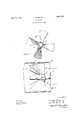
In the following description reference will be made to the accompanying drawings forming part hereof and in which Figure l is a front view partly in section of an air rotor embodying the features of the invention, and
Fig. 2 is a side view of the air rotor and of the oil tube on which it is mounted and a sectional View of the air blast pipe in which it is arranged.
Referring to the drawings the stationary air whirler or turbulator l is provided with spiral vanes 2 of small width at the center and of increasing width to the periphery. The tips of the vanes 2 are shaped, in outline in vertical projection, as arcs of one circle curved to fit the blast pipe. On the air entering side the edges 3, of the vanes are substantially perpendicular to the axis of the air rotor, and on the air leaving side the edges 4 of the vanes are inclined outwardly from the center and away from the edges 3.
5 is an oil tube upon which the air whirler is mounted and fixed against rotation. 6 is an air blast pipe of substantially circular cross section and its purpose is to supply an air blast to an oil burner.
The width of the vanes for rotating air at different diameter Zones is in approximation to the volume of air passing at the different diameter zones. In a pipe of circular cross section the volume of air passing at the center is smaller per inch of diameter than is the case toward the periphery. By the described construction in which the vanes are of small width at the center and increasing width toward the periphery, the width of vane for rotating air is in approximation to 1928. Serial No. 293,838.
the volume of air, so that there results a discharge of air into the fire box in the form of an approximately true helix. By confining the flare of the vanes to the face of the air whirler from which the current of air passes to the discharge end of the air blast pipe 6, the accomplishment of the results above referred to is facilitated.
Ve claim:
l. For an oil burner the combination of an air blast pipe of substantially circular cross section, an air whirler Xed against rotation and having spiral vanes with tips shaped as arcs of one circle and lying substantially in one plane and of small width at the center and of increasing width to the periphery, and an oil feed pipe on which the whirler is mounted.
2. For an oil burner the combination of an air blast pipe of substantially circular cross-section, an air whirler iixed against rotation and having spiral vanes with tips shaped as arcs of one circle and lying substantially in one plane and of small width at the center and of increasing width to the periphery, one of the edges of said vane being disposed substantially radially of the air Whirler and the other of the edges of said vanes being inclined outwardly from center, and an oil feed pipe on which the whirler
Priority Applications (1)
| Application Number | Priority Date | Filing Date | Title |
|---|---|---|---|
| US293838A US1852380A (en) | 1928-07-19 | 1928-07-19 | Oil burner |
Applications Claiming Priority (1)
| Application Number | Priority Date | Filing Date | Title |
|---|---|---|---|
| US293838A US1852380A (en) | 1928-07-19 | 1928-07-19 | Oil burner |
Publications (1)
| Publication Number | Publication Date |
|---|---|
| US1852380A true US1852380A (en) | 1932-04-05 |
Family
ID=23130803
Family Applications (1)
| Application Number | Title | Priority Date | Filing Date |
|---|---|---|---|
| US293838A Expired - Lifetime US1852380A (en) | 1928-07-19 | 1928-07-19 | Oil burner |
Country Status (1)
| Country | Link |
|---|---|
| US (1) | US1852380A (en) |
Cited By (5)
| Publication number | Priority date | Publication date | Assignee | Title |
|---|---|---|---|---|
| US2538460A (en) * | 1947-11-24 | 1951-01-16 | Kaveny John Gordon | Gun type oil burner apparatus with air throttling and whirling means |
| US2553130A (en) * | 1946-06-20 | 1951-05-15 | Cadella Anthony | Air directing means for gun type oil burners |
| US2570155A (en) * | 1948-02-25 | 1951-10-02 | Westinghouse Electric Corp | Flow apparatus |
| US3827461A (en) * | 1972-11-21 | 1974-08-06 | Worthington Pump Int Inc | Stream filament mixer for pipe flow |
| US20070215226A1 (en) * | 2003-07-21 | 2007-09-20 | Richter James R | Pipe flow stabilizer |
-
1928
- 1928-07-19 US US293838A patent/US1852380A/en not_active Expired - Lifetime
Cited By (6)
| Publication number | Priority date | Publication date | Assignee | Title |
|---|---|---|---|---|
| US2553130A (en) * | 1946-06-20 | 1951-05-15 | Cadella Anthony | Air directing means for gun type oil burners |
| US2538460A (en) * | 1947-11-24 | 1951-01-16 | Kaveny John Gordon | Gun type oil burner apparatus with air throttling and whirling means |
| US2570155A (en) * | 1948-02-25 | 1951-10-02 | Westinghouse Electric Corp | Flow apparatus |
| US3827461A (en) * | 1972-11-21 | 1974-08-06 | Worthington Pump Int Inc | Stream filament mixer for pipe flow |
| US20070215226A1 (en) * | 2003-07-21 | 2007-09-20 | Richter James R | Pipe flow stabilizer |
| US7730907B2 (en) * | 2003-07-21 | 2010-06-08 | The Metraflex Company | Device, with vanes, for use within a pipeline, and pipeline arrangement including such device |
Similar Documents
| Publication | Publication Date | Title |
|---|---|---|
| US3312386A (en) | Fan | |
| US2380463A (en) | Fluent fuel burner | |
| JP5818908B2 (en) | Axial flow compressor | |
| US1852380A (en) | Oil burner | |
| US2053403A (en) | Air discharge nozzle | |
| US1870013A (en) | Fuel burner | |
| JP6240763B2 (en) | Rotor for thermal turbomachine | |
| US2667326A (en) | Gas turbine | |
| US2724545A (en) | Discharge casings for axial flow engines | |
| US2768497A (en) | Combustion chamber with swirler | |
| US2921542A (en) | Fluid fuel burner | |
| US2628019A (en) | Free air fan | |
| GB710391A (en) | Improvements in radial flow impellers | |
| US1843088A (en) | Centrifugal fan | |
| US2146250A (en) | Oil burner | |
| US2083184A (en) | Fan | |
| US1877350A (en) | Atomizer | |
| US1994461A (en) | Fuel burner | |
| US1738199A (en) | Fuel burner | |
| US2100690A (en) | Mechanical advertising device | |
| US2090566A (en) | Oil burner | |
| US2396867A (en) | Fuel burner | |
| US2158521A (en) | Pulvurized fuel burner | |
| US2379490A (en) | Air distribution to burners | |
| US1497408A (en) | Fan blower |