US1663998A - Means for minimizing fluid pulsations - Google Patents
Means for minimizing fluid pulsations Download PDFInfo
- Publication number
- US1663998A US1663998A US33415A US3341525A US1663998A US 1663998 A US1663998 A US 1663998A US 33415 A US33415 A US 33415A US 3341525 A US3341525 A US 3341525A US 1663998 A US1663998 A US 1663998A
- Authority
- US
- United States
- Prior art keywords
- runner
- discharge
- rings
- pump
- annular
- Prior art date
- Legal status (The legal status is an assumption and is not a legal conclusion. Google has not performed a legal analysis and makes no representation as to the accuracy of the status listed.)
- Expired - Lifetime
Links
Images
Classifications
-
- F—MECHANICAL ENGINEERING; LIGHTING; HEATING; WEAPONS; BLASTING
- F04—POSITIVE - DISPLACEMENT MACHINES FOR LIQUIDS; PUMPS FOR LIQUIDS OR ELASTIC FLUIDS
- F04D—NON-POSITIVE-DISPLACEMENT PUMPS
- F04D29/00—Details, component parts, or accessories
- F04D29/66—Combating cavitation, whirls, noise, vibration or the like; Balancing
- F04D29/669—Combating cavitation, whirls, noise, vibration or the like; Balancing especially adapted for liquid pumps
-
- F—MECHANICAL ENGINEERING; LIGHTING; HEATING; WEAPONS; BLASTING
- F04—POSITIVE - DISPLACEMENT MACHINES FOR LIQUIDS; PUMPS FOR LIQUIDS OR ELASTIC FLUIDS
- F04D—NON-POSITIVE-DISPLACEMENT PUMPS
- F04D29/00—Details, component parts, or accessories
- F04D29/40—Casings; Connections of working fluid
- F04D29/42—Casings; Connections of working fluid for radial or helico-centrifugal pumps
- F04D29/426—Casings; Connections of working fluid for radial or helico-centrifugal pumps especially adapted for liquid pumps
- F04D29/428—Discharge tongues
-
- F—MECHANICAL ENGINEERING; LIGHTING; HEATING; WEAPONS; BLASTING
- F16—ENGINEERING ELEMENTS AND UNITS; GENERAL MEASURES FOR PRODUCING AND MAINTAINING EFFECTIVE FUNCTIONING OF MACHINES OR INSTALLATIONS; THERMAL INSULATION IN GENERAL
- F16L—PIPES; JOINTS OR FITTINGS FOR PIPES; SUPPORTS FOR PIPES, CABLES OR PROTECTIVE TUBING; MEANS FOR THERMAL INSULATION IN GENERAL
- F16L55/00—Devices or appurtenances for use in, or in connection with, pipes or pipe systems
- F16L55/04—Devices damping pulsations or vibrations in fluids
Definitions
- My invention relates to a method of and apparatus for minimizing fluid pulsations and it has for its object to dampen out the effect of fluid pulsations where it is desired 6 to secure a supply of fluid at substantially uniform pressure from a source of pulsatin pressure.
- ore specifically m invention relates to means for obtaining uid pressure substan tially free from pulsations from an lmpeller pump for the operation of sensitive a paratus such, for example, as a tur me governor.
- I provide conduit means both within and external to the pump, through which the discharge of the pump is caused to flow.
- these conduit means are so formed as to define a plurality of successive discharge nozzles, each of which has a radically different discharge co-efiicient in one direction than in the opposite direction. It follows that said pulsations are thus smoothed out and a substantially uniform pressure is secured for application to the governor.
- these discharge orifices Preferably have-a relatively great discharge coeflicient in the direction of fluid flow and a relatively low discharge co-eflicient in a counter direction, thus offering but little or no impediment to a free discharge of fluid.
- uniform as applied to the resultant pressure, it will be understood that I am merely damping out of pressure changes to control the governor.
- a shaft 11 projects through the casing 10-- and may be, for example, an extension of the turbine shaft.
- This shaft carries a pump runner 12, shown in Fig. 2 as of the radial vane type having eight vanes.
- a volute casing 13-13 is formed on the casing 10 and communicates with the interior thereof through an annular port 1414 opposlte the central portion of the runner 12.
- rings 15 and 16 Fixedly mounted on the casing 10 and interposed between said casing and the runner 12 is a pair of rings 15 and 16 which closely abut at their opposing faces, but nevertheless define a narrow discharge passage from the runner12 to the passage lei-14.
- the abuttin faces of the rings 15 and 16 are provide with a plurality of annular flanges and, as shown, the inwardly presented faces 1717 of said flanges define an angle approaching 90 with the axis of the runner 12, whereas the outwardly presented faces 1 818 define a relatively small angle with the axis of the runner 12, and these faces may actually be undercut as shown.
- volute casing 13-13 discharges into a conduit 20 as shown in Fig. 2 and within this conduit is disposed a plurality of frustoconical collars 21-21, each of which for ease and security of mounting is carried on a cylindrical collar 22. These collars may be retained in the conduit 20 as by being stacked between a suitable flange 23 and removable fastening means 24-24.
- a suitable fluid suc as oil
- suc as oil is su plied to the interior of the casing 10 as tiirough a conduit 25 and passes into the inner portion of the runner 12 whence it is thrown outwardly through the blades of said runner and passes via the discharge passage defined by the rings 15 and 16 and the passage 1414 to the volute casing 13, whence it traverses the conduit 20 to any desired load device.
- the action of the vanes of the runner 12 is to cause a slight pulsation in the discharge pressure but, as th fluid sub ect to such pulsation passes through the successsion of annular discharge nozzles defined by the flanges on the rings 15 and 16, the effect of these pulsations is largely damped out for angle in the frusto-conical members 2l21 may give rise to a discharge co-eflicient in the direction of flow of substantially 9 8% with a discharge co-eflicient in the directlon counter to the direction of fluid flow of 50% or less.
- the discharge passage defined by the rings 15 and 16 is relatively narrow as compared with the width of the blades on the runner 12, and this is purposely so arranged that said discharge passage can accommodate only a small portion of the free discharge of the runner 12, it resulting that the fluid is retained in the runner 12 for several revolutions before esca ing, thus being thoroughly freed of air be ore being discharged, for example, to a governor where such entrained air would interfere with successful operation.
- a pump comprising a central revoluble multi-vane runner and a volute discharge chamber surroundin said runner, of a pair of fixed juxtapose rings interposed between said runner and said chamber and defining therebetween an annular discharge port, the juxtaposed faces of said rings being provided with opposing annular flanges, the inwardly presented faces of which define a greater angle with the axis of said runner than do the outwardly presented faces thereof, whereby a plurality of successive annular discharge nozzles is formed, each of which has a greater discharge co-eflicient in an outward direction than in an inward direction.
- a pump comprising a central revoluble multi-vane runner and a volute discharge chamber surrounding said runner, of a pair of fixed juxtaposed rings interposed between said runner and said chamber and defining therebetween an annular discharge port, the juxtaposed faces of said rings being provided with pairs of opposed annular flanges, said pairs of flanges efining successive annular discharge nozzles, each of said discharge nozzles having a different discharge co-etlicient in an outward than in an inward direction.
- a pump comprising a central revoluble multi-vane runner and a volute discharge chamber surroundin said runner, of a pair of fixed juxtaposed rings interposed between said runner and said chamber and defining therebetween an annular discharge port, the juxtaposed faces of said rings being provided with pairs of 5 opposed flanges, said pairs of flanges defining successive discharge nozzles, each of said discharge nozzles having a different discharge co-efiicient in an outward than in an inward direction.
- a pump comprising a central revoluble m'ulti-vane runner and a volute discharge chamber surrounding said runner, of a pair of fixed juxtaposed rings interposed between said runner and said chamber and defining therebetween an annular discharge port, the juxtaposed faces of said rings being provided with pairs of opposed annular flanges, said pairs of flanges defining successive annular discharge nozzles.
Description
H. F. SCHMIDT MEANS FOR MINIMIZING FLUID PULSATIONS Filed May 28, 1925 t M E mm 0 nT 4 Cm u 2 E X O H m m u 2 L i l G 2 I- RI? 1m 2 l 2 M m5 7 a v n f M w March 27, 1928.
ATTORNEY Patented Mar. 27, 1928.
UNITED STATES 1,663,998 PATENT OFFICE.
HENRY I. SCHMIDT, OF LANSDOWNE, PENNSYLVANIA, ASSIGNOR TO WESTINGHOUSE ELECTRIC & MANUFACTURING COMPANY, A CORPORATION OF PENNSYLVANIA.
MEANS FOR MINIMIZING FLUID PULSATIONS.
Application filed Kay 28, 1925. Serial No. 38,415.
My invention relates to a method of and apparatus for minimizing fluid pulsations and it has for its object to dampen out the effect of fluid pulsations where it is desired 6 to secure a supply of fluid at substantially uniform pressure from a source of pulsatin pressure.
ore specifically m invention relates to means for obtaining uid pressure substan tially free from pulsations from an lmpeller pump for the operation of sensitive a paratus such, for example, as a tur me governor.
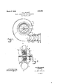
' In the accompanying drawing, Flg. 1 1s a 1 side view, in section, of an impeller pump provided with damping means constructed in accordance with my invention; and Fig.2 is a sectional view of the pump shown 1n Fig. 1, being taken on the plane IIII.
It has been proposed to operate the governors of fluid pressure turbines by means of fluid pressure, generally oil, sa1d pressure being generated by a mult -vane runner carried by or mechamcally connected 5 to the shaft of the turbine.
I find that unless an excessive and 1mpracticable number of vanes are employed, there exists in the discharge column a shght pressure pulsation which may produce undesired vibration in the governing means, particularly if one or more members of such governing means have a natural period approximating the fundamental or an upper harmonic of the pulsating waves.
' In order to obviate this undesirable resuit, I provide conduit means both within and external to the pump, through which the discharge of the pump is caused to flow.
The walls of these conduit means are so formed as to define a plurality of successive discharge nozzles, each of which has a radically different discharge co-efiicient in one direction than in the opposite direction. It follows that said pulsations are thus smoothed out and a substantially uniform pressure is secured for application to the governor. Preferably these discharge orifices have-a relatively great discharge coeflicient in the direction of fluid flow and a relatively low discharge co-eflicient in a counter direction, thus offering but little or no impediment to a free discharge of fluid. By my use of the term uniform as applied to the resultant pressure, it will be understood that I am merely damping out of pressure changes to control the governor.
Referring to the drawing for a more detailed understanding of m invention, I show a pump casing at 10 in ig. 1, this casmg bemg, for example, an extension of an ordinary turbine casing.
A shaft 11 projects through the casing 10-- and may be, for example, an extension of the turbine shaft. This shaft carries a pump runner 12, shown in Fig. 2 as of the radial vane type having eight vanes.
A volute casing 13-13 is formed on the casing 10 and communicates with the interior thereof through an annular port 1414 opposlte the central portion of the runner 12.
Fixedly mounted on the casing 10 and interposed between said casing and the runner 12 is a pair of rings 15 and 16 which closely abut at their opposing faces, but nevertheless define a narrow discharge passage from the runner12 to the passage lei-14. The abuttin faces of the rings 15 and 16 are provide with a plurality of annular flanges and, as shown, the inwardly presented faces 1717 of said flanges define an angle approaching 90 with the axis of the runner 12, whereas the outwardly presented faces 1 818 define a relatively small angle with the axis of the runner 12, and these faces may actually be undercut as shown.
The volute casing 13-13 discharges into a conduit 20 as shown in Fig. 2 and within this conduit is disposed a plurality of frustoconical collars 21-21, each of which for ease and security of mounting is carried on a cylindrical collar 22. These collars may be retained in the conduit 20 as by being stacked between a suitable flange 23 and removable fastening means 24-24.
Having thus described the structure of apparatus constructed in accordance with my invention, the o oration is as follows: A suitable fluid, suc as oil, is su plied to the interior of the casing 10 as tiirough a conduit 25 and passes into the inner portion of the runner 12 whence it is thrown outwardly through the blades of said runner and passes via the discharge passage defined by the rings 15 and 16 and the passage 1414 to the volute casing 13, whence it traverses the conduit 20 to any desired load device. The action of the vanes of the runner 12 is to cause a slight pulsation in the discharge pressure but, as th fluid sub ect to such pulsation passes through the successsion of annular discharge nozzles defined by the flanges on the rings 15 and 16, the effect of these pulsations is largely damped out for angle in the frusto-conical members 2l21 may give rise to a discharge co-eflicient in the direction of flow of substantially 9 8% with a discharge co-eflicient in the directlon counter to the direction of fluid flow of 50% or less.
It will be obvious that the effect of pulsations would be effectively damped out by having the low co-eflicient in the direction of fluid flow and the high co-efiicient in the opposite direction, but such an arrangement would tend to set up an undesirable back pressure and greatly reduce the capacity of the device.
It will be noted that the discharge passage defined by the rings 15 and 16 is relatively narrow as compared with the width of the blades on the runner 12, and this is purposely so arranged that said discharge passage can accommodate only a small portion of the free discharge of the runner 12, it resulting that the fluid is retained in the runner 12 for several revolutions before esca ing, thus being thoroughly freed of air be ore being discharged, for example, to a governor where such entrained air would interfere with successful operation.
This feature is not claimed herein but is specifically described and claimed an application of Roland Marsland, Serial N 0. 33,420, filed May 28, 1925, and assigned to the Westinghouse Electric and Manufacturing Company (Case 6235).
While I have shown my invention in but one form, it will be obvious to those skilled in the art that it is not so limited, but is susceptible of various other changes and modifications, without departing from the d spirit thereof, and I desire, therefore, that only such limitations shall be placed thereupon as are imposed by the prior art or as are specifically set forth in the appended claims.
What I claim is: 1. The combination with a pump compriseach of which has a different discharge 00- efiicient in an outward direction than in an inward direction.
2. The combination with a pump comprising a central revoluble multi-vane runner and a volute discharge chamber surroundin said runner, of a pair of fixed juxtapose rings interposed between said runner and said chamber and defining therebetween an annular discharge port, the juxtaposed faces of said rings being provided with opposing annular flanges, the inwardly presented faces of which define a greater angle with the axis of said runner than do the outwardly presented faces thereof, whereby a plurality of successive annular discharge nozzles is formed, each of which has a greater discharge co-eflicient in an outward direction than in an inward direction.
' 3. The combination with a pump comprising a central revoluble multi-vane runner and a volute discharge chamber surrounding said runner, of a pair of fixed juxtaposed rings interposed between said runner and said chamber and defining therebetween an annular discharge port, the juxta osed faces of said rings being provided wit opposing annular flanges, the inwardly presented faces of which define an angle approaching 90 with the axis of said runner and the outwardly presented faces of which are undercut, whereby a plurality of successive annular nozzles is formed, each of which has a 4. The combination with a pump comprising a central revoluble multi-vane runner and a volute discharge chamber surrounding said runner, of a pair of fixed juxtaposed rings interposed between said runner and said chamber and defining therebetween an annular discharge port, the juxtaposed faces of said rings being provided with pairs of opposed annular flanges, said pairs of flanges efining successive annular discharge nozzles, each of said discharge nozzles having a different discharge co-etlicient in an outward than in an inward direction.
5. The combination with a pump compris ing a central revoluble multi-vane runner and a volute discharge chamber surroundin said runner, of a pair of fixed juxtaposed rings interposed between said runner and said chamber and defining therebetween an annular discharge port, the juxtaposed faces of said rings being provided with pairs of 5 opposed flanges, said pairs of flanges defining successive discharge nozzles, each of said discharge nozzles having a different discharge co-efiicient in an outward than in an inward direction.
6. The combination with a pump comprising a central revoluble m'ulti-vane runner and a volute discharge chamber surrounding said runner, of a pair of fixed juxtaposed rings interposed between said runner and said chamber and defining therebetween an annular discharge port, the juxtaposed faces of said rings being provided with pairs of opposed annular flanges, said pairs of flanges defining successive annular discharge nozzles.
In testimony whereof, I have hereunto subscribed my name this twentieth day of May, 1925.
HENRY F. SCHMIDT.
Priority Applications (1)
| Application Number | Priority Date | Filing Date | Title |
|---|---|---|---|
| US33415A US1663998A (en) | 1925-05-28 | 1925-05-28 | Means for minimizing fluid pulsations |
Applications Claiming Priority (1)
| Application Number | Priority Date | Filing Date | Title |
|---|---|---|---|
| US33415A US1663998A (en) | 1925-05-28 | 1925-05-28 | Means for minimizing fluid pulsations |
Publications (1)
| Publication Number | Publication Date |
|---|---|
| US1663998A true US1663998A (en) | 1928-03-27 |
Family
ID=21870278
Family Applications (1)
| Application Number | Title | Priority Date | Filing Date |
|---|---|---|---|
| US33415A Expired - Lifetime US1663998A (en) | 1925-05-28 | 1925-05-28 | Means for minimizing fluid pulsations |
Country Status (1)
| Country | Link |
|---|---|
| US (1) | US1663998A (en) |
Cited By (19)
| Publication number | Priority date | Publication date | Assignee | Title |
|---|---|---|---|---|
| US2456626A (en) * | 1945-05-15 | 1948-12-21 | Dahnke Henry | Device for the control of flow of fluids |
| US2460370A (en) * | 1946-10-24 | 1949-02-01 | Earl C Stauffer | Housing for oil burners |
| US2670011A (en) * | 1947-10-31 | 1954-02-23 | Snecma | Aerodynamic valve |
| US2763291A (en) * | 1954-01-15 | 1956-09-18 | Snyder Robert Earl | Shock wave absorber |
| US3109584A (en) * | 1963-11-05 | Compressor muffler construction and method for | ||
| US3730673A (en) * | 1971-05-12 | 1973-05-01 | Combustion Unltd Inc | Vent seal |
| US4063848A (en) * | 1976-03-24 | 1977-12-20 | Caterpillar Tractor Co. | Centrifugal compressor vaneless space casing treatment |
| US4212585A (en) * | 1978-01-20 | 1980-07-15 | Northern Research And Engineering Corporation | Centrifugal compressor |
| US4518311A (en) * | 1979-10-03 | 1985-05-21 | Klein, Schanzlin & Becker Aktiengesellschaft | Centrifugal pump |
| FR2619812A1 (en) * | 1987-08-31 | 1989-03-03 | Zinpro Corp | FERRIC ION-CATALYSED PROCESS FOR COMPLEXING ZINC AND / OR MANGANESE WITH ALPHA-AMINO ACIDS |
| EP0341553A1 (en) * | 1988-05-09 | 1989-11-15 | Gec Alsthom Sa | Centrifugal pump |
| US6168378B1 (en) * | 1999-08-10 | 2001-01-02 | Broan-Nutone Llc | Air deflectors to accommodate multiple size ventilator outlets |
| US6360970B1 (en) * | 2000-05-01 | 2002-03-26 | Larry A. Fitzgerald | Water diffuser |
| US20080148728A1 (en) * | 2006-12-20 | 2008-06-26 | International Engine Intellectual Property Company, Llc | Low-restriction turbine outlet housing |
| US20080184705A1 (en) * | 2005-01-25 | 2008-08-07 | Renault S.A.S. | Device for Turbocharging an Internal Combusting Engine Comprising a Pulsation Damping Chamber |
| US7794213B2 (en) * | 2007-05-14 | 2010-09-14 | Honeywell International Inc. | Integrated acoustic damper with thin sheet insert |
| US9004110B2 (en) * | 2013-04-08 | 2015-04-14 | Kuo-Chen Tsai | Water hammer arrestor |
| US10794515B2 (en) * | 2017-12-14 | 2020-10-06 | Thomas A. Hartman | Valve or pipe discharge with velocity reduction discharge plate |
| US20220280004A1 (en) * | 2019-08-05 | 2022-09-08 | Hilti Aktiengesellschaft | Apparatus for Compensating Pressure Surges |
-
1925
- 1925-05-28 US US33415A patent/US1663998A/en not_active Expired - Lifetime
Cited By (21)
| Publication number | Priority date | Publication date | Assignee | Title |
|---|---|---|---|---|
| US3109584A (en) * | 1963-11-05 | Compressor muffler construction and method for | ||
| US2456626A (en) * | 1945-05-15 | 1948-12-21 | Dahnke Henry | Device for the control of flow of fluids |
| US2460370A (en) * | 1946-10-24 | 1949-02-01 | Earl C Stauffer | Housing for oil burners |
| US2670011A (en) * | 1947-10-31 | 1954-02-23 | Snecma | Aerodynamic valve |
| US2763291A (en) * | 1954-01-15 | 1956-09-18 | Snyder Robert Earl | Shock wave absorber |
| US3730673A (en) * | 1971-05-12 | 1973-05-01 | Combustion Unltd Inc | Vent seal |
| US4063848A (en) * | 1976-03-24 | 1977-12-20 | Caterpillar Tractor Co. | Centrifugal compressor vaneless space casing treatment |
| US4212585A (en) * | 1978-01-20 | 1980-07-15 | Northern Research And Engineering Corporation | Centrifugal compressor |
| US4518311A (en) * | 1979-10-03 | 1985-05-21 | Klein, Schanzlin & Becker Aktiengesellschaft | Centrifugal pump |
| FR2619812A1 (en) * | 1987-08-31 | 1989-03-03 | Zinpro Corp | FERRIC ION-CATALYSED PROCESS FOR COMPLEXING ZINC AND / OR MANGANESE WITH ALPHA-AMINO ACIDS |
| EP0341553A1 (en) * | 1988-05-09 | 1989-11-15 | Gec Alsthom Sa | Centrifugal pump |
| US6168378B1 (en) * | 1999-08-10 | 2001-01-02 | Broan-Nutone Llc | Air deflectors to accommodate multiple size ventilator outlets |
| US6360970B1 (en) * | 2000-05-01 | 2002-03-26 | Larry A. Fitzgerald | Water diffuser |
| US20080184705A1 (en) * | 2005-01-25 | 2008-08-07 | Renault S.A.S. | Device for Turbocharging an Internal Combusting Engine Comprising a Pulsation Damping Chamber |
| US7958728B2 (en) * | 2005-01-25 | 2011-06-14 | Renault S.A.S. | Device for turbocharging an internal combusting engine comprising a pulsation damping chamber |
| US20080148728A1 (en) * | 2006-12-20 | 2008-06-26 | International Engine Intellectual Property Company, Llc | Low-restriction turbine outlet housing |
| US7562528B2 (en) * | 2006-12-20 | 2009-07-21 | International Engine Intellectual Property Company Llc | Low-restriction turbine outlet housing |
| US7794213B2 (en) * | 2007-05-14 | 2010-09-14 | Honeywell International Inc. | Integrated acoustic damper with thin sheet insert |
| US9004110B2 (en) * | 2013-04-08 | 2015-04-14 | Kuo-Chen Tsai | Water hammer arrestor |
| US10794515B2 (en) * | 2017-12-14 | 2020-10-06 | Thomas A. Hartman | Valve or pipe discharge with velocity reduction discharge plate |
| US20220280004A1 (en) * | 2019-08-05 | 2022-09-08 | Hilti Aktiengesellschaft | Apparatus for Compensating Pressure Surges |
Similar Documents
| Publication | Publication Date | Title |
|---|---|---|
| US1663998A (en) | Means for minimizing fluid pulsations | |
| US3251539A (en) | Centrifugal gas compressors | |
| US3171353A (en) | Centrifugal fluid pump | |
| GB1225445A (en) | ||
| GB1270905A (en) | Cooling system for an axial flow elastic fluid utilizing machine | |
| US3556680A (en) | Aerodynamic pressure-wave machine | |
| GB1387480A (en) | Energy transfer machine | |
| JP2023052513A (en) | Method and arrangement to minimize noise and excitation of structures due to cavity acoustic modes | |
| US3493169A (en) | Bleed for compressor | |
| US2958456A (en) | Multi-stage aerofoil-bladed compressors | |
| US2578617A (en) | Multistage centrifugal compressor | |
| GB191214668A (en) | Improvements in Turbo-pumps or Fans. | |
| US4227855A (en) | Turbomachine | |
| US1156549A (en) | Elastic-fluid turbine. | |
| US2441239A (en) | Blower apparatus | |
| US1896809A (en) | Multistage turbine | |
| US2527971A (en) | Axial-flow compressor | |
| GB761937A (en) | Improvements in or relating to a rotary fluid pressure converting device such as a turbine, compressor, pump or the like | |
| US2300758A (en) | Blading and balancing piston arrangement | |
| GB1013835A (en) | Improvements in or relating to axial-flow turbines, compressors and exhausters | |
| US2269235A (en) | Multistage elastic fluid turbine | |
| US912133A (en) | Centrifugal fan or pump. | |
| US2323941A (en) | Centrifugal compressor | |
| GB336840A (en) | Improvements in and relating to centrifugal pumps and the like | |
| US1052291A (en) | Centrifugal blower-wheel. |