EP2988363A1 - Components with multiple energization elements for biomedical devices - Google Patents
Components with multiple energization elements for biomedical devices Download PDFInfo
- Publication number
- EP2988363A1 EP2988363A1 EP15181868.9A EP15181868A EP2988363A1 EP 2988363 A1 EP2988363 A1 EP 2988363A1 EP 15181868 A EP15181868 A EP 15181868A EP 2988363 A1 EP2988363 A1 EP 2988363A1
- Authority
- EP
- European Patent Office
- Prior art keywords
- battery
- cathode
- current collector
- separator
- elements
- Prior art date
- Legal status (The legal status is an assumption and is not a legal conclusion. Google has not performed a legal analysis and makes no representation as to the accuracy of the status listed.)
- Granted
Links
- 238000000034 method Methods 0.000 claims abstract description 104
- 239000000126 substance Substances 0.000 claims description 79
- 239000000203 mixture Substances 0.000 claims description 77
- 125000006850 spacer group Chemical group 0.000 claims description 49
- YXFVVABEGXRONW-UHFFFAOYSA-N Toluene Chemical compound CC1=CC=CC=C1 YXFVVABEGXRONW-UHFFFAOYSA-N 0.000 claims description 39
- HCHKCACWOHOZIP-UHFFFAOYSA-N Zinc Chemical compound [Zn] HCHKCACWOHOZIP-UHFFFAOYSA-N 0.000 claims description 29
- 239000002243 precursor Substances 0.000 claims description 29
- 229910052725 zinc Inorganic materials 0.000 claims description 29
- 239000011701 zinc Substances 0.000 claims description 29
- NUJOXMJBOLGQSY-UHFFFAOYSA-N manganese dioxide Chemical compound O=[Mn]=O NUJOXMJBOLGQSY-UHFFFAOYSA-N 0.000 claims description 22
- 229910052751 metal Inorganic materials 0.000 claims description 15
- 239000002184 metal Substances 0.000 claims description 15
- 230000008859 change Effects 0.000 claims description 14
- XUIMIQQOPSSXEZ-UHFFFAOYSA-N Silicon Chemical compound [Si] XUIMIQQOPSSXEZ-UHFFFAOYSA-N 0.000 claims description 13
- 229910052710 silicon Inorganic materials 0.000 claims description 13
- 239000010703 silicon Substances 0.000 claims description 13
- WHXSMMKQMYFTQS-UHFFFAOYSA-N Lithium Chemical compound [Li] WHXSMMKQMYFTQS-UHFFFAOYSA-N 0.000 claims description 11
- 238000005259 measurement Methods 0.000 claims description 11
- 230000002950 deficient Effects 0.000 claims description 10
- 229910052744 lithium Inorganic materials 0.000 claims description 10
- OKTJSMMVPCPJKN-UHFFFAOYSA-N Carbon Chemical compound [C] OKTJSMMVPCPJKN-UHFFFAOYSA-N 0.000 claims description 9
- 150000003839 salts Chemical class 0.000 claims description 9
- PXHVJJICTQNCMI-UHFFFAOYSA-N Nickel Chemical compound [Ni] PXHVJJICTQNCMI-UHFFFAOYSA-N 0.000 claims description 8
- 229910002804 graphite Inorganic materials 0.000 claims description 8
- 239000010439 graphite Substances 0.000 claims description 8
- 229910021383 artificial graphite Inorganic materials 0.000 claims description 7
- GELKBWJHTRAYNV-UHFFFAOYSA-K lithium iron phosphate Chemical compound [Li+].[Fe+2].[O-]P([O-])([O-])=O GELKBWJHTRAYNV-UHFFFAOYSA-K 0.000 claims description 7
- 238000010902 jet-milling Methods 0.000 claims description 5
- 229910052759 nickel Inorganic materials 0.000 claims description 4
- 229910052709 silver Inorganic materials 0.000 claims description 4
- 239000004332 silver Substances 0.000 claims description 4
- DGAQECJNVWCQMB-PUAWFVPOSA-M Ilexoside XXIX Chemical compound C[C@@H]1CC[C@@]2(CC[C@@]3(C(=CC[C@H]4[C@]3(CC[C@@H]5[C@@]4(CC[C@@H](C5(C)C)OS(=O)(=O)[O-])C)C)[C@@H]2[C@]1(C)O)C)C(=O)O[C@H]6[C@@H]([C@H]([C@@H]([C@H](O6)CO)O)O)O.[Na+] DGAQECJNVWCQMB-PUAWFVPOSA-M 0.000 claims description 3
- BQCADISMDOOEFD-UHFFFAOYSA-N Silver Chemical compound [Ag] BQCADISMDOOEFD-UHFFFAOYSA-N 0.000 claims description 3
- 229910017052 cobalt Inorganic materials 0.000 claims description 3
- 239000010941 cobalt Substances 0.000 claims description 3
- GUTLYIVDDKVIGB-UHFFFAOYSA-N cobalt atom Chemical compound [Co] GUTLYIVDDKVIGB-UHFFFAOYSA-N 0.000 claims description 3
- 229910052708 sodium Inorganic materials 0.000 claims description 3
- 239000011734 sodium Substances 0.000 claims description 3
- 229910052720 vanadium Inorganic materials 0.000 claims description 3
- LEONUFNNVUYDNQ-UHFFFAOYSA-N vanadium atom Chemical compound [V] LEONUFNNVUYDNQ-UHFFFAOYSA-N 0.000 claims description 3
- 239000000560 biocompatible material Substances 0.000 abstract 1
- 239000010410 layer Substances 0.000 description 162
- 239000003792 electrolyte Substances 0.000 description 85
- 239000000463 material Substances 0.000 description 62
- 238000012545 processing Methods 0.000 description 39
- 238000013461 design Methods 0.000 description 37
- 239000004820 Pressure-sensitive adhesive Substances 0.000 description 35
- 239000012528 membrane Substances 0.000 description 30
- 239000000017 hydrogel Substances 0.000 description 29
- -1 lithium hexafluorophosphate Chemical compound 0.000 description 27
- 230000008569 process Effects 0.000 description 26
- 238000009472 formulation Methods 0.000 description 25
- 230000006870 function Effects 0.000 description 23
- 230000000670 limiting effect Effects 0.000 description 23
- 238000012360 testing method Methods 0.000 description 22
- 239000011888 foil Substances 0.000 description 21
- 239000004094 surface-active agent Substances 0.000 description 21
- XLYOFNOQVPJJNP-UHFFFAOYSA-N water Substances O XLYOFNOQVPJJNP-UHFFFAOYSA-N 0.000 description 20
- PEDCQBHIVMGVHV-UHFFFAOYSA-N Glycerine Chemical compound OCC(O)CO PEDCQBHIVMGVHV-UHFFFAOYSA-N 0.000 description 19
- 238000004806 packaging method and process Methods 0.000 description 19
- 229920002367 Polyisobutene Polymers 0.000 description 18
- 238000004519 manufacturing process Methods 0.000 description 18
- 230000008901 benefit Effects 0.000 description 17
- 239000000243 solution Substances 0.000 description 17
- 229920000139 polyethylene terephthalate Polymers 0.000 description 16
- 239000005020 polyethylene terephthalate Substances 0.000 description 16
- 239000002904 solvent Substances 0.000 description 16
- 239000012790 adhesive layer Substances 0.000 description 15
- 239000006257 cathode slurry Substances 0.000 description 12
- 229920002981 polyvinylidene fluoride Polymers 0.000 description 12
- 230000004888 barrier function Effects 0.000 description 11
- 239000003990 capacitor Substances 0.000 description 11
- 239000002002 slurry Substances 0.000 description 11
- JIAARYAFYJHUJI-UHFFFAOYSA-L zinc dichloride Chemical compound [Cl-].[Cl-].[Zn+2] JIAARYAFYJHUJI-UHFFFAOYSA-L 0.000 description 11
- 239000004743 Polypropylene Substances 0.000 description 10
- 238000000576 coating method Methods 0.000 description 10
- 230000000694 effects Effects 0.000 description 10
- 238000003698 laser cutting Methods 0.000 description 10
- 239000007788 liquid Substances 0.000 description 10
- 239000000758 substrate Substances 0.000 description 10
- 230000003746 surface roughness Effects 0.000 description 10
- BQCIDUSAKPWEOX-UHFFFAOYSA-N 1,1-Difluoroethene Chemical compound FC(F)=C BQCIDUSAKPWEOX-UHFFFAOYSA-N 0.000 description 9
- NLXLAEXVIDQMFP-UHFFFAOYSA-N Ammonia chloride Chemical compound [NH4+].[Cl-] NLXLAEXVIDQMFP-UHFFFAOYSA-N 0.000 description 9
- 230000015572 biosynthetic process Effects 0.000 description 9
- 238000002955 isolation Methods 0.000 description 9
- 229920000642 polymer Polymers 0.000 description 9
- 239000000853 adhesive Substances 0.000 description 8
- 230000001070 adhesive effect Effects 0.000 description 8
- QVGXLLKOCUKJST-UHFFFAOYSA-N atomic oxygen Chemical compound [O] QVGXLLKOCUKJST-UHFFFAOYSA-N 0.000 description 8
- 230000001276 controlling effect Effects 0.000 description 8
- 238000005520 cutting process Methods 0.000 description 8
- 230000001965 increasing effect Effects 0.000 description 8
- 238000002156 mixing Methods 0.000 description 8
- 239000001301 oxygen Substances 0.000 description 8
- 229910052760 oxygen Inorganic materials 0.000 description 8
- 238000003860 storage Methods 0.000 description 8
- 239000004698 Polyethylene Substances 0.000 description 7
- FAPWRFPIFSIZLT-UHFFFAOYSA-M Sodium chloride Chemical compound [Na+].[Cl-] FAPWRFPIFSIZLT-UHFFFAOYSA-M 0.000 description 7
- 238000013459 approach Methods 0.000 description 7
- 239000002585 base Substances 0.000 description 7
- 230000000903 blocking effect Effects 0.000 description 7
- 239000011248 coating agent Substances 0.000 description 7
- 230000000873 masking effect Effects 0.000 description 7
- 230000035699 permeability Effects 0.000 description 7
- 229920000098 polyolefin Polymers 0.000 description 7
- 239000000047 product Substances 0.000 description 7
- 230000002829 reductive effect Effects 0.000 description 7
- 238000006243 chemical reaction Methods 0.000 description 6
- 239000005329 float glass Substances 0.000 description 6
- 239000000843 powder Substances 0.000 description 6
- 239000011592 zinc chloride Substances 0.000 description 6
- 235000005074 zinc chloride Nutrition 0.000 description 6
- KMTRUDSVKNLOMY-UHFFFAOYSA-N Ethylene carbonate Chemical compound O=C1OCCO1 KMTRUDSVKNLOMY-UHFFFAOYSA-N 0.000 description 5
- 238000005266 casting Methods 0.000 description 5
- 239000012141 concentrate Substances 0.000 description 5
- 230000007547 defect Effects 0.000 description 5
- 238000009792 diffusion process Methods 0.000 description 5
- 239000003085 diluting agent Substances 0.000 description 5
- 238000005516 engineering process Methods 0.000 description 5
- 238000011049 filling Methods 0.000 description 5
- 230000001939 inductive effect Effects 0.000 description 5
- 150000001282 organosilanes Chemical class 0.000 description 5
- 239000004065 semiconductor Substances 0.000 description 5
- 239000011780 sodium chloride Substances 0.000 description 5
- 238000012546 transfer Methods 0.000 description 5
- 229910001369 Brass Inorganic materials 0.000 description 4
- RYGMFSIKBFXOCR-UHFFFAOYSA-N Copper Chemical compound [Cu] RYGMFSIKBFXOCR-UHFFFAOYSA-N 0.000 description 4
- UFHFLCQGNIYNRP-UHFFFAOYSA-N Hydrogen Chemical compound [H][H] UFHFLCQGNIYNRP-UHFFFAOYSA-N 0.000 description 4
- 229920005987 OPPANOL® Polymers 0.000 description 4
- KWYUFKZDYYNOTN-UHFFFAOYSA-M Potassium hydroxide Chemical compound [OH-].[K+] KWYUFKZDYYNOTN-UHFFFAOYSA-M 0.000 description 4
- RTAQQCXQSZGOHL-UHFFFAOYSA-N Titanium Chemical compound [Ti] RTAQQCXQSZGOHL-UHFFFAOYSA-N 0.000 description 4
- 230000004913 activation Effects 0.000 description 4
- 239000000654 additive Substances 0.000 description 4
- 230000004075 alteration Effects 0.000 description 4
- 235000019270 ammonium chloride Nutrition 0.000 description 4
- 239000003125 aqueous solvent Substances 0.000 description 4
- 239000010951 brass Substances 0.000 description 4
- 238000010276 construction Methods 0.000 description 4
- 229910052802 copper Inorganic materials 0.000 description 4
- 239000010949 copper Substances 0.000 description 4
- 238000007599 discharging Methods 0.000 description 4
- SNRUBQQJIBEYMU-UHFFFAOYSA-N dodecane Chemical compound CCCCCCCCCCCC SNRUBQQJIBEYMU-UHFFFAOYSA-N 0.000 description 4
- 239000008151 electrolyte solution Substances 0.000 description 4
- 229940021013 electrolyte solution Drugs 0.000 description 4
- JBTWLSYIZRCDFO-UHFFFAOYSA-N ethyl methyl carbonate Chemical compound CCOC(=O)OC JBTWLSYIZRCDFO-UHFFFAOYSA-N 0.000 description 4
- 238000010348 incorporation Methods 0.000 description 4
- 238000012856 packing Methods 0.000 description 4
- 239000006187 pill Substances 0.000 description 4
- 229920003023 plastic Polymers 0.000 description 4
- 239000004033 plastic Substances 0.000 description 4
- 229920000036 polyvinylpyrrolidone Polymers 0.000 description 4
- 239000001267 polyvinylpyrrolidone Substances 0.000 description 4
- 235000013855 polyvinylpyrrolidone Nutrition 0.000 description 4
- 229910000679 solder Inorganic materials 0.000 description 4
- 239000010936 titanium Substances 0.000 description 4
- 229910052719 titanium Inorganic materials 0.000 description 4
- KFZMGEQAYNKOFK-UHFFFAOYSA-N Isopropanol Chemical compound CC(C)O KFZMGEQAYNKOFK-UHFFFAOYSA-N 0.000 description 3
- FYYHWMGAXLPEAU-UHFFFAOYSA-N Magnesium Chemical compound [Mg] FYYHWMGAXLPEAU-UHFFFAOYSA-N 0.000 description 3
- 230000009471 action Effects 0.000 description 3
- 230000002411 adverse Effects 0.000 description 3
- 229910052782 aluminium Inorganic materials 0.000 description 3
- XAGFODPZIPBFFR-UHFFFAOYSA-N aluminium Chemical compound [Al] XAGFODPZIPBFFR-UHFFFAOYSA-N 0.000 description 3
- 230000009286 beneficial effect Effects 0.000 description 3
- 239000006229 carbon black Substances 0.000 description 3
- 230000001427 coherent effect Effects 0.000 description 3
- 239000000470 constituent Substances 0.000 description 3
- 238000005260 corrosion Methods 0.000 description 3
- IEJIGPNLZYLLBP-UHFFFAOYSA-N dimethyl carbonate Chemical compound COC(=O)OC IEJIGPNLZYLLBP-UHFFFAOYSA-N 0.000 description 3
- 238000001035 drying Methods 0.000 description 3
- 239000007772 electrode material Substances 0.000 description 3
- 238000009713 electroplating Methods 0.000 description 3
- 239000012530 fluid Substances 0.000 description 3
- 239000011521 glass Substances 0.000 description 3
- 238000003780 insertion Methods 0.000 description 3
- 230000037431 insertion Effects 0.000 description 3
- 239000005001 laminate film Substances 0.000 description 3
- 238000010030 laminating Methods 0.000 description 3
- 239000011777 magnesium Substances 0.000 description 3
- 229910052749 magnesium Inorganic materials 0.000 description 3
- 239000000178 monomer Substances 0.000 description 3
- 230000003647 oxidation Effects 0.000 description 3
- 238000007254 oxidation reaction Methods 0.000 description 3
- 229920000435 poly(dimethylsiloxane) Polymers 0.000 description 3
- 229920000573 polyethylene Polymers 0.000 description 3
- 239000011148 porous material Substances 0.000 description 3
- 230000001681 protective effect Effects 0.000 description 3
- 238000006722 reduction reaction Methods 0.000 description 3
- 230000004044 response Effects 0.000 description 3
- 239000000565 sealant Substances 0.000 description 3
- 238000007789 sealing Methods 0.000 description 3
- 238000000926 separation method Methods 0.000 description 3
- 239000011877 solvent mixture Substances 0.000 description 3
- 229920003048 styrene butadiene rubber Polymers 0.000 description 3
- 238000009736 wetting Methods 0.000 description 3
- 229920002818 (Hydroxyethyl)methacrylate Polymers 0.000 description 2
- USFZMSVCRYTOJT-UHFFFAOYSA-N Ammonium acetate Chemical compound N.CC(O)=O USFZMSVCRYTOJT-UHFFFAOYSA-N 0.000 description 2
- 239000005695 Ammonium acetate Substances 0.000 description 2
- OYPRJOBELJOOCE-UHFFFAOYSA-N Calcium Chemical compound [Ca] OYPRJOBELJOOCE-UHFFFAOYSA-N 0.000 description 2
- 239000004593 Epoxy Substances 0.000 description 2
- WOBHKFSMXKNTIM-UHFFFAOYSA-N Hydroxyethyl methacrylate Chemical compound CC(=C)C(=O)OCCO WOBHKFSMXKNTIM-UHFFFAOYSA-N 0.000 description 2
- XEEYBQQBJWHFJM-UHFFFAOYSA-N Iron Chemical compound [Fe] XEEYBQQBJWHFJM-UHFFFAOYSA-N 0.000 description 2
- HBBGRARXTFLTSG-UHFFFAOYSA-N Lithium ion Chemical compound [Li+] HBBGRARXTFLTSG-UHFFFAOYSA-N 0.000 description 2
- FXHOOIRPVKKKFG-UHFFFAOYSA-N N,N-Dimethylacetamide Chemical compound CN(C)C(C)=O FXHOOIRPVKKKFG-UHFFFAOYSA-N 0.000 description 2
- IMNFDUFMRHMDMM-UHFFFAOYSA-N N-Heptane Chemical compound CCCCCCC IMNFDUFMRHMDMM-UHFFFAOYSA-N 0.000 description 2
- 239000004614 Process Aid Substances 0.000 description 2
- ATJFFYVFTNAWJD-UHFFFAOYSA-N Tin Chemical compound [Sn] ATJFFYVFTNAWJD-UHFFFAOYSA-N 0.000 description 2
- BPKGOZPBGXJDEP-UHFFFAOYSA-N [C].[Zn] Chemical compound [C].[Zn] BPKGOZPBGXJDEP-UHFFFAOYSA-N 0.000 description 2
- 239000006096 absorbing agent Substances 0.000 description 2
- DPXJVFZANSGRMM-UHFFFAOYSA-N acetic acid;2,3,4,5,6-pentahydroxyhexanal;sodium Chemical compound [Na].CC(O)=O.OCC(O)C(O)C(O)C(O)C=O DPXJVFZANSGRMM-UHFFFAOYSA-N 0.000 description 2
- ZOIORXHNWRGPMV-UHFFFAOYSA-N acetic acid;zinc Chemical compound [Zn].CC(O)=O.CC(O)=O ZOIORXHNWRGPMV-UHFFFAOYSA-N 0.000 description 2
- 239000002253 acid Substances 0.000 description 2
- 230000003213 activating effect Effects 0.000 description 2
- 235000019257 ammonium acetate Nutrition 0.000 description 2
- 229940043376 ammonium acetate Drugs 0.000 description 2
- 239000003963 antioxidant agent Substances 0.000 description 2
- SESFRYSPDFLNCH-UHFFFAOYSA-N benzyl benzoate Chemical compound C=1C=CC=CC=1C(=O)OCC1=CC=CC=C1 SESFRYSPDFLNCH-UHFFFAOYSA-N 0.000 description 2
- 239000011230 binding agent Substances 0.000 description 2
- 230000008827 biological function Effects 0.000 description 2
- 239000011575 calcium Substances 0.000 description 2
- 229910052791 calcium Inorganic materials 0.000 description 2
- 239000001768 carboxy methyl cellulose Substances 0.000 description 2
- 239000013626 chemical specie Substances 0.000 description 2
- 230000002939 deleterious effect Effects 0.000 description 2
- 238000012217 deletion Methods 0.000 description 2
- 230000037430 deletion Effects 0.000 description 2
- 229940113088 dimethylacetamide Drugs 0.000 description 2
- 238000000605 extraction Methods 0.000 description 2
- 239000000945 filler Substances 0.000 description 2
- 239000007789 gas Substances 0.000 description 2
- PCHJSUWPFVWCPO-UHFFFAOYSA-N gold Chemical compound [Au] PCHJSUWPFVWCPO-UHFFFAOYSA-N 0.000 description 2
- 229910052737 gold Inorganic materials 0.000 description 2
- 239000010931 gold Substances 0.000 description 2
- 239000003112 inhibitor Substances 0.000 description 2
- 229910052500 inorganic mineral Inorganic materials 0.000 description 2
- 239000012212 insulator Substances 0.000 description 2
- 150000002642 lithium compounds Chemical class 0.000 description 2
- 229910001416 lithium ion Inorganic materials 0.000 description 2
- 235000010755 mineral Nutrition 0.000 description 2
- 239000011707 mineral Substances 0.000 description 2
- 238000012986 modification Methods 0.000 description 2
- 230000004048 modification Effects 0.000 description 2
- 238000012544 monitoring process Methods 0.000 description 2
- 230000008450 motivation Effects 0.000 description 2
- 229920003052 natural elastomer Polymers 0.000 description 2
- 229920001194 natural rubber Polymers 0.000 description 2
- 230000003287 optical effect Effects 0.000 description 2
- 239000002245 particle Substances 0.000 description 2
- 230000037361 pathway Effects 0.000 description 2
- 238000009832 plasma treatment Methods 0.000 description 2
- BASFCYQUMIYNBI-UHFFFAOYSA-N platinum Chemical compound [Pt] BASFCYQUMIYNBI-UHFFFAOYSA-N 0.000 description 2
- 239000005518 polymer electrolyte Substances 0.000 description 2
- 239000002952 polymeric resin Substances 0.000 description 2
- 229920001155 polypropylene Polymers 0.000 description 2
- 239000004810 polytetrafluoroethylene Substances 0.000 description 2
- 229920001343 polytetrafluoroethylene Polymers 0.000 description 2
- 230000005855 radiation Effects 0.000 description 2
- 230000009467 reduction Effects 0.000 description 2
- 230000001105 regulatory effect Effects 0.000 description 2
- 230000008439 repair process Effects 0.000 description 2
- 238000000518 rheometry Methods 0.000 description 2
- NDVLTYZPCACLMA-UHFFFAOYSA-N silver oxide Chemical compound [O-2].[Ag+].[Ag+] NDVLTYZPCACLMA-UHFFFAOYSA-N 0.000 description 2
- 239000002356 single layer Substances 0.000 description 2
- 235000019812 sodium carboxymethyl cellulose Nutrition 0.000 description 2
- 229920001027 sodium carboxymethylcellulose Polymers 0.000 description 2
- 239000007787 solid Substances 0.000 description 2
- 230000008961 swelling Effects 0.000 description 2
- 229920003051 synthetic elastomer Polymers 0.000 description 2
- 239000005061 synthetic rubber Substances 0.000 description 2
- 229920001169 thermoplastic Polymers 0.000 description 2
- 229910052718 tin Inorganic materials 0.000 description 2
- 239000011135 tin Substances 0.000 description 2
- 230000001052 transient effect Effects 0.000 description 2
- 238000004506 ultrasonic cleaning Methods 0.000 description 2
- 239000011800 void material Substances 0.000 description 2
- 239000000080 wetting agent Substances 0.000 description 2
- 239000004246 zinc acetate Substances 0.000 description 2
- 235000013904 zinc acetate Nutrition 0.000 description 2
- WYTZZXDRDKSJID-UHFFFAOYSA-N (3-aminopropyl)triethoxysilane Chemical compound CCO[Si](OCC)(OCC)CCCN WYTZZXDRDKSJID-UHFFFAOYSA-N 0.000 description 1
- ICBJBNAUJWZPBY-UHFFFAOYSA-N 2-hydroxyethyl 3-methylbut-2-enoate Chemical compound CC(=CC(=O)OCCO)C ICBJBNAUJWZPBY-UHFFFAOYSA-N 0.000 description 1
- 229920001817 Agar Polymers 0.000 description 1
- 239000004215 Carbon black (E152) Substances 0.000 description 1
- 229920000298 Cellophane Polymers 0.000 description 1
- OIFBSDVPJOWBCH-UHFFFAOYSA-N Diethyl carbonate Chemical compound CCOC(=O)OCC OIFBSDVPJOWBCH-UHFFFAOYSA-N 0.000 description 1
- 241000251729 Elasmobranchii Species 0.000 description 1
- LFQSCWFLJHTTHZ-UHFFFAOYSA-N Ethanol Chemical compound CCO LFQSCWFLJHTTHZ-UHFFFAOYSA-N 0.000 description 1
- 244000043261 Hevea brasiliensis Species 0.000 description 1
- 241000282412 Homo Species 0.000 description 1
- 239000013032 Hydrocarbon resin Substances 0.000 description 1
- 229910052493 LiFePO4 Inorganic materials 0.000 description 1
- 241001124569 Lycaenidae Species 0.000 description 1
- 241001465754 Metazoa Species 0.000 description 1
- CERQOIWHTDAKMF-UHFFFAOYSA-N Methacrylic acid Chemical compound CC(=C)C(O)=O CERQOIWHTDAKMF-UHFFFAOYSA-N 0.000 description 1
- 239000002033 PVDF binder Substances 0.000 description 1
- 229920003171 Poly (ethylene oxide) Polymers 0.000 description 1
- 239000011398 Portland cement Substances 0.000 description 1
- 229910003676 SiBr4 Inorganic materials 0.000 description 1
- 229910003910 SiCl4 Inorganic materials 0.000 description 1
- 229920002472 Starch Polymers 0.000 description 1
- GUCYFKSBFREPBC-UHFFFAOYSA-N [phenyl-(2,4,6-trimethylbenzoyl)phosphoryl]-(2,4,6-trimethylphenyl)methanone Chemical compound CC1=CC(C)=CC(C)=C1C(=O)P(=O)(C=1C=CC=CC=1)C(=O)C1=C(C)C=C(C)C=C1C GUCYFKSBFREPBC-UHFFFAOYSA-N 0.000 description 1
- 238000002835 absorbance Methods 0.000 description 1
- 150000007513 acids Chemical class 0.000 description 1
- 229920006397 acrylic thermoplastic Polymers 0.000 description 1
- 239000011149 active material Substances 0.000 description 1
- 230000000996 additive effect Effects 0.000 description 1
- 239000008272 agar Substances 0.000 description 1
- 230000032683 aging Effects 0.000 description 1
- 238000013019 agitation Methods 0.000 description 1
- 229910045601 alloy Inorganic materials 0.000 description 1
- 239000000956 alloy Substances 0.000 description 1
- 239000003708 ampul Substances 0.000 description 1
- 239000010405 anode material Substances 0.000 description 1
- 230000003078 antioxidant effect Effects 0.000 description 1
- 229960000892 attapulgite Drugs 0.000 description 1
- XNEFYCZVKIDDMS-UHFFFAOYSA-N avobenzone Chemical compound C1=CC(OC)=CC=C1C(=O)CC(=O)C1=CC=C(C(C)(C)C)C=C1 XNEFYCZVKIDDMS-UHFFFAOYSA-N 0.000 description 1
- 229960005193 avobenzone Drugs 0.000 description 1
- 229910052788 barium Inorganic materials 0.000 description 1
- DSAJWYNOEDNPEQ-UHFFFAOYSA-N barium atom Chemical compound [Ba] DSAJWYNOEDNPEQ-UHFFFAOYSA-N 0.000 description 1
- 239000003637 basic solution Substances 0.000 description 1
- 229960002903 benzyl benzoate Drugs 0.000 description 1
- 230000005540 biological transmission Effects 0.000 description 1
- 239000006172 buffering agent Substances 0.000 description 1
- 239000013590 bulk material Substances 0.000 description 1
- 239000006227 byproduct Substances 0.000 description 1
- 239000000378 calcium silicate Substances 0.000 description 1
- 229910052918 calcium silicate Inorganic materials 0.000 description 1
- OYACROKNLOSFPA-UHFFFAOYSA-N calcium;dioxido(oxo)silane Chemical compound [Ca+2].[O-][Si]([O-])=O OYACROKNLOSFPA-UHFFFAOYSA-N 0.000 description 1
- 238000003490 calendering Methods 0.000 description 1
- 229910052799 carbon Inorganic materials 0.000 description 1
- 150000004649 carbonic acid derivatives Chemical class 0.000 description 1
- 230000015556 catabolic process Effects 0.000 description 1
- 230000019522 cellular metabolic process Effects 0.000 description 1
- 239000002817 coal dust Substances 0.000 description 1
- 230000003750 conditioning effect Effects 0.000 description 1
- 239000006258 conductive agent Substances 0.000 description 1
- 238000011109 contamination Methods 0.000 description 1
- 239000007799 cork Substances 0.000 description 1
- 230000007797 corrosion Effects 0.000 description 1
- 238000004132 cross linking Methods 0.000 description 1
- 230000009849 deactivation Effects 0.000 description 1
- 230000003247 decreasing effect Effects 0.000 description 1
- 238000006731 degradation reaction Methods 0.000 description 1
- 239000008367 deionised water Substances 0.000 description 1
- 229910021641 deionized water Inorganic materials 0.000 description 1
- 238000000151 deposition Methods 0.000 description 1
- 230000001627 detrimental effect Effects 0.000 description 1
- 238000011161 development Methods 0.000 description 1
- 230000018109 developmental process Effects 0.000 description 1
- 238000004090 dissolution Methods 0.000 description 1
- 238000009826 distribution Methods 0.000 description 1
- 239000011263 electroactive material Substances 0.000 description 1
- 238000004070 electrodeposition Methods 0.000 description 1
- 239000002001 electrolyte material Substances 0.000 description 1
- 238000004049 embossing Methods 0.000 description 1
- 238000005538 encapsulation Methods 0.000 description 1
- 230000007613 environmental effect Effects 0.000 description 1
- 125000003700 epoxy group Chemical group 0.000 description 1
- 238000001704 evaporation Methods 0.000 description 1
- 230000008020 evaporation Effects 0.000 description 1
- 230000001747 exhibiting effect Effects 0.000 description 1
- 238000002474 experimental method Methods 0.000 description 1
- 239000000835 fiber Substances 0.000 description 1
- 230000005669 field effect Effects 0.000 description 1
- 239000012634 fragment Substances 0.000 description 1
- 125000000524 functional group Chemical group 0.000 description 1
- 238000011990 functional testing Methods 0.000 description 1
- 239000000499 gel Substances 0.000 description 1
- 239000003349 gelling agent Substances 0.000 description 1
- 239000003292 glue Substances 0.000 description 1
- 230000036541 health Effects 0.000 description 1
- 229930195733 hydrocarbon Natural products 0.000 description 1
- 229920006270 hydrocarbon resin Polymers 0.000 description 1
- 150000002430 hydrocarbons Chemical class 0.000 description 1
- 230000002209 hydrophobic effect Effects 0.000 description 1
- XLYOFNOQVPJJNP-UHFFFAOYSA-M hydroxide Chemical compound [OH-] XLYOFNOQVPJJNP-UHFFFAOYSA-M 0.000 description 1
- 150000004679 hydroxides Chemical class 0.000 description 1
- XLSMFKSTNGKWQX-UHFFFAOYSA-N hydroxyacetone Chemical compound CC(=O)CO XLSMFKSTNGKWQX-UHFFFAOYSA-N 0.000 description 1
- 238000007654 immersion Methods 0.000 description 1
- 238000002513 implantation Methods 0.000 description 1
- 239000012535 impurity Substances 0.000 description 1
- 238000001727 in vivo Methods 0.000 description 1
- 238000001802 infusion Methods 0.000 description 1
- 239000003999 initiator Substances 0.000 description 1
- 230000000266 injurious effect Effects 0.000 description 1
- 239000002198 insoluble material Substances 0.000 description 1
- 238000005305 interferometry Methods 0.000 description 1
- 150000002500 ions Chemical class 0.000 description 1
- 229910052742 iron Inorganic materials 0.000 description 1
- CYPPCCJJKNISFK-UHFFFAOYSA-J kaolinite Chemical compound [OH-].[OH-].[OH-].[OH-].[Al+3].[Al+3].[O-][Si](=O)O[Si]([O-])=O CYPPCCJJKNISFK-UHFFFAOYSA-J 0.000 description 1
- 229910052622 kaolinite Inorganic materials 0.000 description 1
- 238000003475 lamination Methods 0.000 description 1
- 239000012633 leachable Substances 0.000 description 1
- 239000011244 liquid electrolyte Substances 0.000 description 1
- 239000012705 liquid precursor Substances 0.000 description 1
- 229910002102 lithium manganese oxide Inorganic materials 0.000 description 1
- 229910003002 lithium salt Inorganic materials 0.000 description 1
- 159000000002 lithium salts Chemical class 0.000 description 1
- VGYDTVNNDKLMHX-UHFFFAOYSA-N lithium;manganese;nickel;oxocobalt Chemical compound [Li].[Mn].[Ni].[Co]=O VGYDTVNNDKLMHX-UHFFFAOYSA-N 0.000 description 1
- VLXXBCXTUVRROQ-UHFFFAOYSA-N lithium;oxido-oxo-(oxomanganiooxy)manganese Chemical compound [Li+].[O-][Mn](=O)O[Mn]=O VLXXBCXTUVRROQ-UHFFFAOYSA-N 0.000 description 1
- 238000001459 lithography Methods 0.000 description 1
- 238000011068 loading method Methods 0.000 description 1
- 230000007774 longterm Effects 0.000 description 1
- 238000000691 measurement method Methods 0.000 description 1
- 230000007246 mechanism Effects 0.000 description 1
- 229910000000 metal hydroxide Inorganic materials 0.000 description 1
- 229910044991 metal oxide Inorganic materials 0.000 description 1
- 150000004706 metal oxides Chemical class 0.000 description 1
- 229910052914 metal silicate Inorganic materials 0.000 description 1
- 150000002739 metals Chemical class 0.000 description 1
- 239000010445 mica Substances 0.000 description 1
- 229910052618 mica group Inorganic materials 0.000 description 1
- 239000004005 microsphere Substances 0.000 description 1
- 238000003801 milling Methods 0.000 description 1
- 238000012806 monitoring device Methods 0.000 description 1
- 239000012457 nonaqueous media Substances 0.000 description 1
- 239000003921 oil Substances 0.000 description 1
- 230000008520 organization Effects 0.000 description 1
- 230000001590 oxidative effect Effects 0.000 description 1
- NWVVVBRKAWDGAB-UHFFFAOYSA-N p-methoxyphenol Chemical compound COC1=CC=C(O)C=C1 NWVVVBRKAWDGAB-UHFFFAOYSA-N 0.000 description 1
- 239000005022 packaging material Substances 0.000 description 1
- 229910052625 palygorskite Inorganic materials 0.000 description 1
- 230000036961 partial effect Effects 0.000 description 1
- 229910052697 platinum Inorganic materials 0.000 description 1
- 229920003229 poly(methyl methacrylate) Polymers 0.000 description 1
- 229920002239 polyacrylonitrile Polymers 0.000 description 1
- 229920000647 polyepoxide Polymers 0.000 description 1
- 229920002338 polyhydroxyethylmethacrylate Polymers 0.000 description 1
- 229920006254 polymer film Polymers 0.000 description 1
- 239000003505 polymerization initiator Substances 0.000 description 1
- 238000006116 polymerization reaction Methods 0.000 description 1
- 229920001296 polysiloxane Polymers 0.000 description 1
- 238000002360 preparation method Methods 0.000 description 1
- 238000003825 pressing Methods 0.000 description 1
- 238000007639 printing Methods 0.000 description 1
- 238000001314 profilometry Methods 0.000 description 1
- 239000000376 reactant Substances 0.000 description 1
- 239000004627 regenerated cellulose Substances 0.000 description 1
- 239000013557 residual solvent Substances 0.000 description 1
- 230000002441 reversible effect Effects 0.000 description 1
- 238000005096 rolling process Methods 0.000 description 1
- 238000007790 scraping Methods 0.000 description 1
- 239000013535 sea water Substances 0.000 description 1
- 238000009517 secondary packaging Methods 0.000 description 1
- 238000007086 side reaction Methods 0.000 description 1
- AIFMYMZGQVTROK-UHFFFAOYSA-N silicon tetrabromide Chemical compound Br[Si](Br)(Br)Br AIFMYMZGQVTROK-UHFFFAOYSA-N 0.000 description 1
- FDNAPBUWERUEDA-UHFFFAOYSA-N silicon tetrachloride Chemical compound Cl[Si](Cl)(Cl)Cl FDNAPBUWERUEDA-UHFFFAOYSA-N 0.000 description 1
- 229910001923 silver oxide Inorganic materials 0.000 description 1
- 239000007784 solid electrolyte Substances 0.000 description 1
- 238000004528 spin coating Methods 0.000 description 1
- 235000015096 spirit Nutrition 0.000 description 1
- 238000005507 spraying Methods 0.000 description 1
- 239000008107 starch Substances 0.000 description 1
- 235000019698 starch Nutrition 0.000 description 1
- 230000003068 static effect Effects 0.000 description 1
- 238000005728 strengthening Methods 0.000 description 1
- 239000000454 talc Substances 0.000 description 1
- 229910052623 talc Inorganic materials 0.000 description 1
- ISXSCDLOGDJUNJ-UHFFFAOYSA-N tert-butyl prop-2-enoate Chemical compound CC(C)(C)OC(=O)C=C ISXSCDLOGDJUNJ-UHFFFAOYSA-N 0.000 description 1
- 238000010998 test method Methods 0.000 description 1
- 231100000331 toxic Toxicity 0.000 description 1
- 230000002588 toxic effect Effects 0.000 description 1
- 238000009489 vacuum treatment Methods 0.000 description 1
- 238000011179 visual inspection Methods 0.000 description 1
- 238000003466 welding Methods 0.000 description 1
- 230000037303 wrinkles Effects 0.000 description 1
- 239000010457 zeolite Substances 0.000 description 1
- SZKTYYIADWRVSA-UHFFFAOYSA-N zinc manganese(2+) oxygen(2-) Chemical class [O--].[O--].[Mn++].[Zn++] SZKTYYIADWRVSA-UHFFFAOYSA-N 0.000 description 1
Images


Classifications
-
- H—ELECTRICITY
- H01—ELECTRIC ELEMENTS
- H01M—PROCESSES OR MEANS, e.g. BATTERIES, FOR THE DIRECT CONVERSION OF CHEMICAL ENERGY INTO ELECTRICAL ENERGY
- H01M6/00—Primary cells; Manufacture thereof
- H01M6/40—Printed batteries, e.g. thin film batteries
-
- H—ELECTRICITY
- H01—ELECTRIC ELEMENTS
- H01M—PROCESSES OR MEANS, e.g. BATTERIES, FOR THE DIRECT CONVERSION OF CHEMICAL ENERGY INTO ELECTRICAL ENERGY
- H01M10/00—Secondary cells; Manufacture thereof
- H01M10/42—Methods or arrangements for servicing or maintenance of secondary cells or secondary half-cells
- H01M10/425—Structural combination with electronic components, e.g. electronic circuits integrated to the outside of the casing
-
- H—ELECTRICITY
- H01—ELECTRIC ELEMENTS
- H01M—PROCESSES OR MEANS, e.g. BATTERIES, FOR THE DIRECT CONVERSION OF CHEMICAL ENERGY INTO ELECTRICAL ENERGY
- H01M6/00—Primary cells; Manufacture thereof
- H01M6/04—Cells with aqueous electrolyte
- H01M6/045—Cells with aqueous electrolyte characterised by aqueous electrolyte
-
- A—HUMAN NECESSITIES
- A61—MEDICAL OR VETERINARY SCIENCE; HYGIENE
- A61B—DIAGNOSIS; SURGERY; IDENTIFICATION
- A61B5/00—Measuring for diagnostic purposes; Identification of persons
- A61B5/0002—Remote monitoring of patients using telemetry, e.g. transmission of vital signals via a communication network
- A61B5/0031—Implanted circuitry
-
- A—HUMAN NECESSITIES
- A61—MEDICAL OR VETERINARY SCIENCE; HYGIENE
- A61F—FILTERS IMPLANTABLE INTO BLOOD VESSELS; PROSTHESES; DEVICES PROVIDING PATENCY TO, OR PREVENTING COLLAPSING OF, TUBULAR STRUCTURES OF THE BODY, e.g. STENTS; ORTHOPAEDIC, NURSING OR CONTRACEPTIVE DEVICES; FOMENTATION; TREATMENT OR PROTECTION OF EYES OR EARS; BANDAGES, DRESSINGS OR ABSORBENT PADS; FIRST-AID KITS
- A61F2/00—Filters implantable into blood vessels; Prostheses, i.e. artificial substitutes or replacements for parts of the body; Appliances for connecting them with the body; Devices providing patency to, or preventing collapsing of, tubular structures of the body, e.g. stents
- A61F2/02—Prostheses implantable into the body
- A61F2/14—Eye parts, e.g. lenses, corneal implants; Implanting instruments specially adapted therefor; Artificial eyes
-
- A—HUMAN NECESSITIES
- A61—MEDICAL OR VETERINARY SCIENCE; HYGIENE
- A61N—ELECTROTHERAPY; MAGNETOTHERAPY; RADIATION THERAPY; ULTRASOUND THERAPY
- A61N1/00—Electrotherapy; Circuits therefor
- A61N1/18—Applying electric currents by contact electrodes
- A61N1/32—Applying electric currents by contact electrodes alternating or intermittent currents
- A61N1/36—Applying electric currents by contact electrodes alternating or intermittent currents for stimulation
- A61N1/372—Arrangements in connection with the implantation of stimulators
- A61N1/378—Electrical supply
-
- B—PERFORMING OPERATIONS; TRANSPORTING
- B29—WORKING OF PLASTICS; WORKING OF SUBSTANCES IN A PLASTIC STATE IN GENERAL
- B29D—PRODUCING PARTICULAR ARTICLES FROM PLASTICS OR FROM SUBSTANCES IN A PLASTIC STATE
- B29D11/00—Producing optical elements, e.g. lenses or prisms
- B29D11/00009—Production of simple or compound lenses
- B29D11/00038—Production of contact lenses
-
- B—PERFORMING OPERATIONS; TRANSPORTING
- B29—WORKING OF PLASTICS; WORKING OF SUBSTANCES IN A PLASTIC STATE IN GENERAL
- B29D—PRODUCING PARTICULAR ARTICLES FROM PLASTICS OR FROM SUBSTANCES IN A PLASTIC STATE
- B29D11/00—Producing optical elements, e.g. lenses or prisms
- B29D11/0074—Production of other optical elements not provided for in B29D11/00009- B29D11/0073
- B29D11/00807—Producing lenses combined with electronics, e.g. chips
- B29D11/00817—Producing electro-active lenses or lenses with energy receptors, e.g. batteries or antennas
-
- G—PHYSICS
- G02—OPTICS
- G02C—SPECTACLES; SUNGLASSES OR GOGGLES INSOFAR AS THEY HAVE THE SAME FEATURES AS SPECTACLES; CONTACT LENSES
- G02C7/00—Optical parts
- G02C7/02—Lenses; Lens systems ; Methods of designing lenses
- G02C7/04—Contact lenses for the eyes
-
- H—ELECTRICITY
- H01—ELECTRIC ELEMENTS
- H01L—SEMICONDUCTOR DEVICES NOT COVERED BY CLASS H10
- H01L29/00—Semiconductor devices adapted for rectifying, amplifying, oscillating or switching, or capacitors or resistors with at least one potential-jump barrier or surface barrier, e.g. PN junction depletion layer or carrier concentration layer; Details of semiconductor bodies or of electrodes thereof ; Multistep manufacturing processes therefor
- H01L29/66—Types of semiconductor device ; Multistep manufacturing processes therefor
- H01L29/68—Types of semiconductor device ; Multistep manufacturing processes therefor controllable by only the electric current supplied, or only the electric potential applied, to an electrode which does not carry the current to be rectified, amplified or switched
- H01L29/70—Bipolar devices
- H01L29/72—Transistor-type devices, i.e. able to continuously respond to applied control signals
-
- H—ELECTRICITY
- H01—ELECTRIC ELEMENTS
- H01M—PROCESSES OR MEANS, e.g. BATTERIES, FOR THE DIRECT CONVERSION OF CHEMICAL ENERGY INTO ELECTRICAL ENERGY
- H01M10/00—Secondary cells; Manufacture thereof
- H01M10/05—Accumulators with non-aqueous electrolyte
- H01M10/052—Li-accumulators
- H01M10/0525—Rocking-chair batteries, i.e. batteries with lithium insertion or intercalation in both electrodes; Lithium-ion batteries
-
- H—ELECTRICITY
- H01—ELECTRIC ELEMENTS
- H01M—PROCESSES OR MEANS, e.g. BATTERIES, FOR THE DIRECT CONVERSION OF CHEMICAL ENERGY INTO ELECTRICAL ENERGY
- H01M10/00—Secondary cells; Manufacture thereof
- H01M10/42—Methods or arrangements for servicing or maintenance of secondary cells or secondary half-cells
-
- H—ELECTRICITY
- H01—ELECTRIC ELEMENTS
- H01M—PROCESSES OR MEANS, e.g. BATTERIES, FOR THE DIRECT CONVERSION OF CHEMICAL ENERGY INTO ELECTRICAL ENERGY
- H01M10/00—Secondary cells; Manufacture thereof
- H01M10/60—Heating or cooling; Temperature control
- H01M10/62—Heating or cooling; Temperature control specially adapted for specific applications
-
- H—ELECTRICITY
- H01—ELECTRIC ELEMENTS
- H01M—PROCESSES OR MEANS, e.g. BATTERIES, FOR THE DIRECT CONVERSION OF CHEMICAL ENERGY INTO ELECTRICAL ENERGY
- H01M4/00—Electrodes
- H01M4/02—Electrodes composed of, or comprising, active material
- H01M4/06—Electrodes for primary cells
-
- B—PERFORMING OPERATIONS; TRANSPORTING
- B29—WORKING OF PLASTICS; WORKING OF SUBSTANCES IN A PLASTIC STATE IN GENERAL
- B29L—INDEXING SCHEME ASSOCIATED WITH SUBCLASS B29C, RELATING TO PARTICULAR ARTICLES
- B29L2011/00—Optical elements, e.g. lenses, prisms
- B29L2011/0016—Lenses
- B29L2011/0041—Contact lenses
-
- G—PHYSICS
- G02—OPTICS
- G02C—SPECTACLES; SUNGLASSES OR GOGGLES INSOFAR AS THEY HAVE THE SAME FEATURES AS SPECTACLES; CONTACT LENSES
- G02C7/00—Optical parts
- G02C7/02—Lenses; Lens systems ; Methods of designing lenses
- G02C7/08—Auxiliary lenses; Arrangements for varying focal length
- G02C7/081—Ophthalmic lenses with variable focal length
- G02C7/083—Electrooptic lenses
-
- H—ELECTRICITY
- H01—ELECTRIC ELEMENTS
- H01M—PROCESSES OR MEANS, e.g. BATTERIES, FOR THE DIRECT CONVERSION OF CHEMICAL ENERGY INTO ELECTRICAL ENERGY
- H01M10/00—Secondary cells; Manufacture thereof
- H01M10/04—Construction or manufacture in general
- H01M10/0445—Multimode batteries, e.g. containing auxiliary cells or electrodes switchable in parallel or series connections
-
- H—ELECTRICITY
- H01—ELECTRIC ELEMENTS
- H01M—PROCESSES OR MEANS, e.g. BATTERIES, FOR THE DIRECT CONVERSION OF CHEMICAL ENERGY INTO ELECTRICAL ENERGY
- H01M10/00—Secondary cells; Manufacture thereof
- H01M10/05—Accumulators with non-aqueous electrolyte
- H01M10/052—Li-accumulators
-
- H—ELECTRICITY
- H01—ELECTRIC ELEMENTS
- H01M—PROCESSES OR MEANS, e.g. BATTERIES, FOR THE DIRECT CONVERSION OF CHEMICAL ENERGY INTO ELECTRICAL ENERGY
- H01M10/00—Secondary cells; Manufacture thereof
- H01M10/05—Accumulators with non-aqueous electrolyte
- H01M10/058—Construction or manufacture
- H01M10/0585—Construction or manufacture of accumulators having only flat construction elements, i.e. flat positive electrodes, flat negative electrodes and flat separators
-
- Y—GENERAL TAGGING OF NEW TECHNOLOGICAL DEVELOPMENTS; GENERAL TAGGING OF CROSS-SECTIONAL TECHNOLOGIES SPANNING OVER SEVERAL SECTIONS OF THE IPC; TECHNICAL SUBJECTS COVERED BY FORMER USPC CROSS-REFERENCE ART COLLECTIONS [XRACs] AND DIGESTS
- Y02—TECHNOLOGIES OR APPLICATIONS FOR MITIGATION OR ADAPTATION AGAINST CLIMATE CHANGE
- Y02E—REDUCTION OF GREENHOUSE GAS [GHG] EMISSIONS, RELATED TO ENERGY GENERATION, TRANSMISSION OR DISTRIBUTION
- Y02E60/00—Enabling technologies; Technologies with a potential or indirect contribution to GHG emissions mitigation
- Y02E60/10—Energy storage using batteries
-
- Y—GENERAL TAGGING OF NEW TECHNOLOGICAL DEVELOPMENTS; GENERAL TAGGING OF CROSS-SECTIONAL TECHNOLOGIES SPANNING OVER SEVERAL SECTIONS OF THE IPC; TECHNICAL SUBJECTS COVERED BY FORMER USPC CROSS-REFERENCE ART COLLECTIONS [XRACs] AND DIGESTS
- Y02—TECHNOLOGIES OR APPLICATIONS FOR MITIGATION OR ADAPTATION AGAINST CLIMATE CHANGE
- Y02P—CLIMATE CHANGE MITIGATION TECHNOLOGIES IN THE PRODUCTION OR PROCESSING OF GOODS
- Y02P70/00—Climate change mitigation technologies in the production process for final industrial or consumer products
- Y02P70/50—Manufacturing or production processes characterised by the final manufactured product
Definitions
- the methods and apparatus to form the biocompatible energization elements involve forming a separator element of the energization element.
- the active elements including anodes, cathodes and electrolytes may be electrochemically connected and may interact with the formed separator elements.
- a field of use for the methods and apparatus may include any biocompatible device or product that requires energization elements.
- These medical devices can include, for example, implantable pacemakers, electronic pills for monitoring and/or testing a biological function, surgical devices with active components, contact lenses, infusion pumps, and neurostimulators.
- Added functionality and an increase in performance to the many of the aforementioned medical devices has been theorized and developed.
- many of these devices now require self-contained energization means that are compatible with the size and shape requirements of these devices, as well as the energy requirements of the new energized components.
- Some medical devices may include components such as semiconductor devices that perform a variety of functions and can be incorporated into many biocompatible and/or implantable devices.
- semiconductor components require energy and, thus, energization elements should preferably also be included in such biocompatible devices.
- the topology and relatively small size of the biocompatible devices creates novel and challenging environments for the definition of various functionalities.
- biocompatible energization elements are disclosed which afford manufacturing advantages while creating structures which may significantly contain the battery chemistry.
- the structural design may also provide for inherent control of the quantities of the energization elements found within the battery elements.
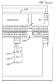
- One general aspect includes a biocompatible energization element which may also include a gap spacer layer.
- the biocompatible energization element may also include at least a first hole located in the gap spacer layer.
- the biocompatible energization element may also include a cathode spacer layer, where the cathode spacer layer is attached to the gap spacer layer.
- the biocompatible energization element may also include at least a second hole located in the cathode spacer layer, where the second hole is aligned to the first hole, and where the second hole is smaller than the first hole such that when the first hole and the second hole are aligned there is a ridge of cathode spacer layer exposed in the first hole.
- the biocompatible energization element may also include a separator layer, where the separator layer is placed within the first hole in the gap spacer layer and is adhered to the ridge of cathode spacer layer.
- the biocompatible energization element may also include a cavity between sides of the second hole and a first surface of the separator layer, where the cavity is filled with cathode chemicals.
- the biocompatible energization element may also include a first current collector coated with anode chemicals.
- the biocompatible energization element may also include a second current collector, where the second current collector is in electrical connection with the cathode chemicals.
- the biocompatible energization element may also include an electrolyte including electrolyte chemicals.
- Implementations may include the biocompatible energization element where the cathode chemicals, anode chemicals and electrolyte chemicals are consistent with multiple charging and discharging cycles of the energization
- the biocompatible energization element may also include examples where the cathode chemicals include a salt of lithium.
- the biocompatible energization element may include lithium iron phosphate.
- the biocompatible energization element may also include intercalated metal atoms.
- the biocompatible energization element may also include intercalated lithium atoms.
- the biocompatible energization element may also include one or more of lead, nickel, lithium, cobalt, zinc, sodium, vanadium, silver, or silicon.
- the biocompatible energization element may also include sodium carboxymethyl cellulose.
- the biocompatible energization element may also include examples where the cathode chemicals include one or more of synthetic graphite and carbon black.
- the biocompatible energization element may also include examples where the cathode chemicals include one or more of styrene butadiene rubber.
- the biocompatible energization element may also include lithium hexafluorophosate.
- the biocompatible energization element may include examples where the biocompatible energization element is electrically connected to an electroactive element within a biomedical device.
- the biocompatible energization element may also include examples where the biomedical device is an ophthalmic device. In some examples the ophthalmic device may be a contact lens.
- the biocompatible energization element may also include examples where the electrolyte includes lithium hexafluorophosphate.
- the biocompatible energization element may also include examples where the separator precursor mixture includes one or more of poly(vinylidene fluoride), poly(dimethylsiloxane), n-n dimethyl acetamide). Additional examples may also include glycerol.
- the biocompatible energization element may also include the biocompatible energization element where the separator includes glycerol in a concentration at least 90 percent and the concentration may be reduced from a concentration of glycerol in the separator precursor mixture.
- the biocompatible energization element may be included within a biomedical device.
- the biocompatible energization element may be included into an ophthalmic device where the ophthalmic device is a contact lens.
- One general aspect includes a method of operating a biomedical device, the method including: obtaining a laminate battery device with multiple energization elements for an biomedical device including powered components.
- the laminate battery device includes a cathode spacer layer, a first hole located in the cathode spacer layer, and a first current collector coated with anode chemicals, where the first current collector is attached to a first surface of the cathode spacer layer.
- the laminate battery device may include examples where a first cavity is created between sides of the first hole and a first surface of the first current collector coated with anode chemicals.
- the laminate battery device also includes a separator layer, where the separator layer is formed within the first cavity after a separator precursor mixture is dispensed into the cavity.
- the method also includes a second cavity between sides of the first hole and a first surface of the separator layer, where the second cavity is filled with cathode chemicals.
- the method also includes the laminate battery device which includes a second current collector, where the second current collector is in electrical connection with the cathode chemicals.
- the method also includes an electrolyte including electrolyte chemicals.
- the method of also includes placing the laminate battery device into electrical contact with powered components, where electrical current from the laminate battery device flows through at least one electrical transistor, where the at least one electrical transistor is located within a controller; where at least a first and a second discrete energization element are located within the laminate battery device, where the first discrete energization element generates a first raw battery power and the second discrete energization element generates a second raw battery power; and where a power management unit is electrically connected to the first and the second discrete energization elements.
- the power management unit receives the first raw battery power from the first discrete energization element and the second raw battery power from the second discrete energization element.
- the method may further include utilizing the second measurement to determine a defectiveness of the second discrete energization element.
- the method may also include an example where the determination is that the second discrete energization element is not defective, and in that case the switch controller controls a change of state of a second switch connecting to the second discrete energization element.
- the method may also include examples where the change of state of the second switch connects the second discrete energization element to the first power output.
- One general aspect includes an apparatus for powering a biomedical device; the apparatus may include a laminate battery device with multiple energization elements for a biomedical device including powered components.
- the apparatus may include a cathode spacer layer and a first hole located in the cathode spacer layer.
- the apparatus also includes a first current collector coated with anode chemicals, where the first current collector is attached to a first surface of the cathode spacer layer, and where a first cavity is created between sides of the first hole and a first surface of the first current collector coated with anode chemicals.
- the apparatus also includes a separator layer, where the separator layer is formed within the first cavity after a separator precursor mixture is dispensed into the cavity.
- the apparatus also includes a second cavity between sides of the first hole and a first surface of the separator layer, where the second cavity is filled with cathode chemicals.
- the apparatus also includes a second current collector, where the second current collector is in electrical connection with the cathode chemicals.
- the apparatus also includes a third current collector, where the third current collector is physically segmented from the second current collector and is in electrical connection with the cathode chemicals within a second hole located in the cathode spacer layer; and an interconnect junction element, where the interconnection junction element makes electrical connection to the first current collector, the second current collector and the third current collector, where an electrical diode within the interconnect junction element makes connection to at least one of the first current collector, the second current collector and the third current collector.
- the separator element within the energization elements may be formed with novel methods and may comprise novel materials.
- detailed descriptions of various embodiments are described. The description of both preferred and alternative embodiments are exemplary embodiments only, and various modifications and alterations may be apparent to those skilled in the art. Therefore, the exemplary embodiments do not limit the scope of this application.
- the three-dimensional biocompatible energization elements are designed for use in or proximate to the body of a living organism.
- a particular class of energization elements may be batteries that are fabricated in layers. The layers may also be classified as laminate layers. A battery formed in this manner may be classified as a laminar battery.
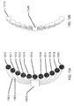
- FIG. 1A An example of a biomedical device that may incorporate the Energization Elements, batteries, of the present invention may be an electroactive focal-adjusting contact lens.
- contact lens insert 100 an example of such a contact lens insert is depicted as contact lens insert 100.
- electroactive element 120 may accommodate focal characteristic changes in response to controlling voltages.
- a circuit 105 to provide those controlling voltage signals as well as to provide other functions such as controlling sensing of the environment for external control signals, may be powered by a biocompatible battery element 110.
- the battery element 110 may be found as multiple major pieces, in this case three pieces, and may include the various configurations of battery chemistry elements as has been discussed.
- the battery elements 110 may have various interconnect features to join together pieces as may be depicted underlying the region of interconnect 114.
- the battery elements 110 may be connected to a circuit element that may have its own substrate 111 upon which interconnect features 125 may be located.
- the circuit 105 which may be in the form of an integrated circuit, may be electrically and physically connected to the substrate 111 and its interconnect features 125.
- a cross sectional relief of a contact lens 150 may comprise contact lens insert 100 and its discussed constituents.
- the contact lens insert 100 may be encapsulated into a skirt of contact lens hydrogel 155 which may encapsulate the contact lens insert 100 and provide a comfortable interface of the contact lens 150 to a user's eye.
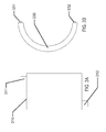
- the battery elements may be formed in a two-dimensional form as depicted in Fig. 1C .
- the battery elements which are depicted in flat form in Fig. 1C , may connect to a circuit element 163, which in the example of Fig. 1C may comprise two major circuit areas 167.
- the circuit element 163 may connect to the battery element at an electrical contact 161 and a physical contact 162.
- the flat structure may be folded into a three-dimensional conical structure as has been described with respect to the present invention.
- a second electrical contact 166 and a second physical contact 164 may be used to connect and physically stabilize the three-dimensional structure.
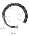
- a representation of this three-dimensional conical structure 180 is illustrated.
- the physical and electrical contact points 181 may also be found and the illustration may be viewed as a three-dimensional view of the resulting structure.
- This structure may include the modular electrical and battery component that will be incorporated with a lens insert into a biocompatible device.
- the segmented components may be relatively circular-shaped 271, square-shaped 272 or rectangular-shaped.
- the rectangles may be small rectangular shapes 273, larger rectangular shapes 274, or even larger rectangular shapes 275.
- the batteries may be formed as flat elements.
- Fig. 3A an example of a rectangular outline 310 of the battery element is depicted with an anode connection 311 and a cathode connection 312.
- Fig. 3B an example of a circular outline 330 of a battery element is depicted with an anode connection 331 and a cathode connection 332.
- the outlines of the battery form may be dimensionally and geometrically configured to fit in custom products.
- custom "free-form” or “free shape” outlines may be formed which may allow the battery configuration to be optimized to fit within a given product.
- a "free-form" example of a flat outline may be arcuate in form.
- the free form may be of such geometry that when formed to a three-dimensional shape, it may take the form of a conical, annular skirt that fits within the constraining confines of a contact lens. It may be clear that similar beneficial geometries may be formed where medical devices have restrictive 2D or 3D shape requirements.
- the batteries according to the present invention may have important aspects relating to safety and biocompatibility.
- batteries for biomedical devices may need to meet requirements above and beyond those for typical usage scenarios.
- design aspects may be considered related to stressing events.
- the safety of an electronic contact lens may need to be considered in the event a user breaks the lens during insertion or removal.
- design aspects may consider the potential for a user to be struck in the eye by a foreign object.
- stressful conditions that may be considered in developing design parameters and constraints may relate to the potential for a user to wear the lens in challenging environments like the environment under water or the environment at high altitude in non-limiting examples.
- pacemakers may be a typical type of biomedical device which may include a battery and which may be implanted in a user for an extended period of time. Accordingly, in some examples, such pacemakers may typically be packaged with welded, hermetic titanium enclosures, or in other examples, multiple layers of encapsulation. Emerging powered biomedical devices may present new challenges for packaging, especially battery packaging. These new devices may be much smaller than existing biomedical devices, for example, an electronic contact lens or pill camera may be significantly smaller than a pacemaker. In such examples, the volume and area available for packaging may be greatly reduced.
- Another area for design considerations may relate to electrical requirements of the device, which may be provided by the battery.
- an appropriate battery may need to meet the full electrical requirements of the system when operating in a non-connected or non-externally powered mode.
- An emerging field of non-connected or non-externally powered biomedical devices may include, for example, vision-correcting contact lenses, health monitoring devices, pill cameras, and novelty devices.
- Recent developments in integrated circuit (IC) technology may permit meaningful electrical operation at very low current levels, for example, picoamps of standby current and microamps of operating current. IC's may also permit very small devices.
- Microbatteries for biomedical applications may be required to meet many simultaneous, challenging requirements.
- the microbattery may be required to have the capability to deliver a suitable operating voltage to an incorporated electrical circuit.
- This operating voltage may be influenced by several factors including the IC process "node,” the output voltage from the circuit to another device, and a particular current consumption target which may also relate to a desired device lifetime.
- nodes may typically be differentiated by the minimum feature size of a transistor, such as its "so-called" transistor channel.
- This physical feature along with other parameters of the IC fabrication, such as gate oxide thickness, may be associated with a resulting rating standard for "turn-on” or “threshold” voltages of field-effect transistors (FET's) fabricated in the given process node.
- FET's field-effect transistors
- it may be common to find FET's with turn-on voltages of 5.0V.
- the FET's may turn-on at 1.2, 1.8, and 2.5V.
- the IC foundry may supply standard cells of digital blocks, for example, inverters and flip-flops that have been characterized and are rated for use over certain voltage ranges.
- Designers chose an IC process node based on several factors including density of digital devices, analog/digital mixed signal devices, leakage current, wiring layers, and availability of specialty devices such as high-voltage FET's. Given these parametric aspects of the electrical components, which may draw power from a microbattery, it may be important for the microbattery power source to be matched to the requirements of the chosen process node and IC design, especially in terms of available voltage and current.
- an electrical circuit powered by a microbattery may connect to another device.
- the microbattery-powered electrical circuit may connect to an actuator or a transducer.
- these may include a light-emitting diode (LED), a sensor, a microelectromechanical system (MEMS) pump, or numerous other such devices.
- LED light-emitting diode
- MEMS microelectromechanical system
- such connected devices may require higher operating voltage conditions than common IC process nodes. For example, a variable-focus lens may require 35V to activate. The operating voltage provided by the battery may therefore be a critical consideration when designing such a system.
- the efficiency of a lens driver to produce 35V from a 1V battery may be significantly less than it might be when operating from a 2V battery. Further requirements, such as die size, may be dramatically different considering the operating parameters of the microbattery as well.
- the open-circuit voltage is the potential produced by the battery cell with infinite load resistance.
- the loaded voltage is the potential produced by the cell with an appropriate, and typically also specified, load impedance placed across the cell terminals.
- the cutoff voltage is typically a voltage at which most of the battery has been discharged.
- the cutoff voltage may represent a voltage, or degree of discharge, below which the battery should not be discharged to avoid deleterious effects such as excessive gassing.
- the cutoff voltage may typically be influenced by the circuit to which the battery is connected, not just the battery itself, for example, the minimum operating voltage of the electronic circuit.
- an alkaline cell may have an open-circuit voltage of 1.6V, a loaded voltage in the range 1.0 to 1.5V, and a cutoff voltage of 1.0V.
- the voltage of a given microbattery cell design may depend upon other factors of the cell chemistry employed. And, different cell chemistry may therefore have different cell voltages.
- Cells may be connected in series to increase voltage; however, this combination may come with tradeoffs to size, internal resistance, and battery complexity. Cells may also be combined in parallel configurations to decrease resistance and increase capacity; however, such a combination may tradeoff size and shelf life.
- Battery capacity may be the ability of a battery to deliver current, or do work, for a period of time. Battery capacity may typically be specified in units such as microamp-hours. A battery that may deliver 1 microamp of current for 1 hour has 1 microamp-hour of capacity. Capacity may typically be increased by increasing the mass (and hence volume) of reactants within a battery device; however, it may be appreciated that biomedical devices may be significantly constrained on available volume. Battery capacity may also be influenced by electrode and electrolyte material.
- a battery may be required to source current over a range of values.
- a leakage current on the order of picoamps to nanoamps may flow through circuits, interconnects, and insulators.
- circuitry may consume quiescent current to sample sensors, run timers, and perform such low power consumption functions.
- Quiescent current consumption may be on the order of nanoamps to milliamps.
- Circuitry may also have even higher peak current demands, for example, when writing flash memory or communicating over radio frequency (RF). This peak current may extend to tens of milliamps or more.
- RF radio frequency
- Shelf life typically refers to the period of time which a battery may survive in storage and still maintain useful operating parameters. Shelf life may be particularly important for biomedical devices for several reasons. Electronic devices may displace non-powered devices, as for example may be the case for the introduction of an electronic contact lens. Products in these existing market spaces may have established shelf life requirements, for example, three years, due to customer, supply chain, and other requirements. It may typically be desired that such specifications not be altered for new products. Shelf life requirements may also be set by the distribution, inventory, and use methods of a device including a microbattery. Accordingly, microbatteries for biomedical devices may have specific shelf life requirements, which may be, for example, measured in the number of years.
- three-dimensional biocompatible energization elements may be rechargeable.
- an inductive coil may also be fabricated on the three-dimensional surface. The inductive coil could then be energized with a radio-frequency ("RF") fob.
- the inductive coil may be connected to the three-dimensional biocompatible energization element to recharge the energization element when RF is applied to the inductive coil.
- photovoltaics may also be fabricated on the three-dimensional surface and connected to the three-dimensional biocompatible energization element. When exposed to light or photons, the photovoltaics will produce electrons to recharge the energization element.
- a battery may function to provide the electrical energy for an electrical system.
- the battery may be electrically connected to the circuit of the electrical system.
- the connections between a circuit and a battery may be classified as interconnects. These interconnects may become increasingly challenging for biomedical microbatteries due to several factors.
- powered biomedical devices may be very small thus allowing little area and volume for the interconnects. The restrictions of size and area may impact the electrical resistance and reliability of the interconnections.
- a battery may contain a liquid electrolyte which could boil at high temperature. This restriction may directly compete with the desire to use a solder interconnect which may, for example, require relatively high temperatures such as 250 degrees Celsius to melt.
- the battery chemistry, including the electrolyte, and the heat source used to form solder based interconnects may be isolated spatially from each other. In the cases of emerging biomedical devices, the small size may preclude the separation of electrolyte and solder joints by sufficient distance to reduce heat conduction.
- Interconnects may allow current to flow to and from the battery in connection with an external circuit. Such interconnects may interface with the environments inside and outside the battery, and may cross the boundary or seal between those environments. These interconnects may be considered as traces, making connections to an external circuit, passing through the battery seal, and then connecting to the current collectors inside the battery. As such, these interconnects may have several requirements. Outside the battery, the interconnects may resemble typical printed circuit traces. They may be soldered to, or otherwise connect to, other traces. In an example where the battery is a separate physical element from a circuit board comprising an integrated circuit, the battery interconnect may allow for connection to the external circuit. This connection may be formed with solder, conductive tape, conductive ink or epoxy, or other means. The interconnect traces may need to survive in the environment outside the battery, for example, not corroding in the presence of oxygen.
- Adhesion may be required between the seal and interconnect in addition to the adhesion which may be required between the seal and battery package.
- Seal integrity may need to be maintained in the presence of electrolyte and other materials inside the battery.
- Interconnects which may typically be metallic, may be known as points of failure in battery packaging. The electrical potential and/or flow of current may increase the tendency for electrolyte to "creep" along the interconnect. Accordingly, an interconnect may need to be engineered to maintain seal integrity.
- the interconnects may interface with the current collectors or may actually form the current collectors.
- the interconnect may need to meet the requirements of the current collectors as described herein, or may need to form an electrical connection to such current collectors.
- metal foils are available in thickness of 25 microns or less, which make them suitable for very thin batteries. Such foil may also be sourced with low surface roughness and contamination, two factors which may be critical for battery performance.
- the foils may include zinc, nickel, brass, copper, titanium, other metals, and various alloys.
- An electrolyte is a component of a battery which facilitates a chemical reaction to take place between the chemical materials of the electrodes.
- Typical electrolytes may be electrochemically active to the electrodes, for example, allowing oxidation and reduction reactions to occur. In some examples, this important electrochemical activity may make for a challenge to creating devices that are biocompatible.
- potassium hydroxide (KOH) may be a commonly used electrolyte in alkaline cells. At high concentration the material has a high pH and may interact unfavorably with various living tissues.
- electrolytes may be employed which may be less electrochemically active; however, these materials may typically result in reduced electrical performance, such as reduced cell voltage and increased cell resistance. Accordingly, one key aspect of the design and engineering of a biomedical microbattery may be the electrolyte. It may be desirable for the electrolyte to be sufficiently active to meet electrical requirements while also being relatively safe for use in- or on-body.
- test scenarios may be used to determine the safety of battery components, in particular electrolytes, to living cells. These results, in conjunction with tests of the battery packaging, may allow engineering design of a battery system that may meet requirements. For example, when developing a powered contact lens, battery electrolytes may be tested on a human corneal cell model. These tests may include experiments on electrolyte concentration, exposure time, and additives. The results of such tests may indicate cell metabolism and other physiological aspects. Tests may also include in-vivo testing on animals and humans.
- Electrolytes for use in the present invention may include zinc chloride, zinc acetate, ammonium acetate, and ammonium chloride in mass concentrations from approximately 0.1 percent to 50 percent, and in a non-limiting example may be approximately 25 percent.
- the specific concentrations may depend on electrochemical activity, battery performance, shelf life, seal integrity, and biocompatibility.
- additives may be mixed into the electrolyte base to alter its characteristics.
- gelling agents such as agar may reduce the ability of the electrolyte to leak out of packing, thereby increasing safety.
- Corrosion inhibitors may be added to the electrolyte, for example, to improve shelf life by reducing the undesired dissolution of the zinc anode into the electrolyte. These inhibitors may positively or adversely affect the safety profile of the battery.
- Wetting agents or surfactants may be added, for example, to allow the electrolyte to wet the separator or to be filled into the battery package. Again, these wetting agents may be positive or negative for safety.
- surfactant may increase the electrical impedance of the cell. Accordingly, the lowest concentration of surfactant to achieve the desired wetting or other properties should be used.
- exemplary surfactants may include TritonTM X-100, TritonTM QS44, and DowfaxTM 3B2 in concentrations from 0.01 percent to 2 percent.
- Novel electrolytes are also emerging which may dramatically improve the safety profile of biomedical microbatteries.
- a class of solid electrolytes may be inherently resistant to leaking while still offering suitable electrical performance.
- Salt water batteries are batteries in which the active materials, the electrodes and electrolyte, are separated until the time of use. Because of this separation, the cells' self-discharge is greatly reduced and shelf life is greatly increased.
- Salt water batteries may be designed from a variety of electrode materials, including zinc, magnesium, aluminum, copper, tin, manganese dioxide, and silver oxide.
- the electrolyte may be actual sea water, for example, water from the ocean flooding the battery upon contact, or may be a specially engineered saline formulation. This type of battery may be particularly useful in contact lenses.
- a saline electrolyte may have superior biocompatibility to classical electrolytes such as potassium hydroxide and zinc chloride.
- Contact lenses are stored in a "packing solution" which is typically a mixture of sodium chloride, perhaps with other salts and buffering agents. This solution has been demonstrated as a battery electrolyte in combination with a zinc anode and manganese dioxide cathode. Other electrolyte and electrode combinations are possible.
- a contact lens using a "salt water” battery may comprise an electrolyte based on sodium chloride, packing solution, or even a specially engineered electrolyte similar to tear fluid. Such a battery could, for example, be activated with packing solution, maintain an opening to the eye, and continue operating with exposure to human tears.
- a reserve cell may be used to meet the shelf life requirements of a contact lens product. Typical contact lenses are specified for storage of 3 years or more. This is a challenging requirement for a battery with a small and thin package.
- a reserve cell for use in a contact lens may have a design similar to those shown in Figs. 1 and 3 , but the electrolyte might not be added at the time of manufacture.
- the electrolyte may be stored in an ampule within the contact lens and connected to the battery, or saline surrounding the battery may be used as the electrolyte.
- a valve or port may be designed to separate the electrolyte from the electrodes until the user activates the lens.
- the electrolyte may be allowed to flow into the battery and form an ionic pathway between the electrodes. This may involve a one-time transfer of electrolyte or may expose the battery for continued diffusion.
- Some battery systems may use or consume electrolyte during the chemical reaction. Accordingly, it may be necessary to engineer a certain volume of electrolyte into the packaged system. This electrolyte may be stored in various locations including the separator or a reservoir.
- a design of a battery system may include a component or components that may function to limit discharge capacity of the battery system. For example, it may be desirable to design the materials and amounts of materials of the anode, cathode, or electrolyte such that one of them may be depleted first during the course of reactions in the battery system. In such an example, the depletion of one of the anode, cathode, or electrolyte may reduce the potential for problematic discharge and side reactions to not take place at lower discharge voltages. These problematic reactions may produce, for example, excessive gas or byproducts which could be detrimental to safety and other factors.
- a modular battery component may be formed according to some aspects and examples of the present invention.
- the modular battery assembly may be a separate component from other parts of the biomedical device.
- such a design may include a modular battery that is separate from the rest of a media insert.
- a modular battery component may be formed in a separate, non-integrated process which may alleviate the need to handle rigid, three-dimensionally formed optical plastic components.
- the sources of manufacturing may be more flexible and may operate in a more parallel mode to the manufacturing of the other components in the biomedical device.
- the fabrication of the modular battery components may be decoupled from the characteristics of three-dimensional (3D) shaped devices.
- 3D three-dimensional
- a modular battery system may be fabricated in a flat or roughly two-dimensional (2D) perspective and then shaped to the appropriate three-dimensional shape.
- a modular battery component may be tested independently of the rest of the biomedical device and yield loss due to battery components may be sorted before assembly.
- the resulting modular battery component may be utilized in various media insert constructs that do not have an appropriate rigid region upon which the battery components may be formed; and, in a still further example, the use of modular battery components may facilitate the use of different options for fabrication technologies than might otherwise be utilized, such as, web-based technology (roll to roll), sheet-based technology (sheet-to-sheet), printing, lithography, and "squeegee" processing.
- the discrete containment aspect of such a device may result in additional material being added to the overall biomedical device construct. Such effects may set a constraint for the use of modular battery solutions when the available space parameters require minimized thickness or volume of solutions.
- Battery shape requirements may be driven at least in part by the application for which the battery is to be used.
- Traditional battery form factors may be cylindrical forms or rectangular prisms, made of metal, and may be geared toward products which require large amounts of power for long durations. These applications may be large enough that they may comprise large form factor batteries.
- planar (2D) solid-state batteries are thin rectangular prisms, typically formed upon inflexible silicon or glass. These planar solid-state batteries may be formed in some examples using silicon wafer-processing technologies.
- low power, flexible batteries may be formed in a pouch construct, using thin foils or plastic to contain the battery chemistry. These batteries may be made flat (2D), and may be designed to function when bowed to a modest out-of-plane (3D) curvature.
- the form factor may require a three-dimensional curvature of the battery component where a radius of that curvature may be on the order of approximately 8.4 mm.
- the nature of such a curvature may be considered to be relatively steep and for reference may approximate the type of curvature found on a human fingertip.
- the nature of a relative steep curvature creates challenging aspects for manufacture.
- a modular battery component may be designed such that it may be fabricated in a flat, two-dimensional manner and then formed into a three-dimensional form of relative high curvature.
- the thickness of the battery component may be an important and limiting parameter.
- battery thickness may be determined by the combined thicknesses of top and bottom sheets, spacer sheets, and adhesive layer thicknesses. Practical manufacturing aspects may drive certain parameters of film thickness to standard values in available sheet stock.
- the films may have minimum thickness values to which they may be specified base upon technical considerations relating to chemical compatibility, moisture / gas impermeability, surface finish, and compatibility with coatings that may be deposited upon the film layers.
- a desired or goal thickness of a finished battery component may be a component thickness that is less than 220 ⁇ m.
- this desired thickness may be driven by the three-dimensional geometry of an exemplary ophthalmic lens device where the battery component may need to be fit inside the available volume defined by a hydrogel lens shape given end user comfort, biocompatibility, and acceptance constraints.
- This volume and its effect on the needs of battery component thickness may be a function of total device thickness specification as well as device specification relating to its width, cone angle, and inner diameter.
- Another important design consideration for the resulting battery component design may relate to the volume available for active battery chemicals and materials in a given battery component design with respect to the resulting chemical energy that may result from that design. This resulting chemical energy may then be balanced for the electrical requirements of a functional biomedical device for its targeted life and operating conditions
- a flexible battery module may facilitate the previously mentioned ability to fabricate the battery form in a two-dimensional (2D) flat form.
- the flexibility of the form may allow the two-dimensional battery to then be formed into an appropriate 3D shape to fit into a biomedical device such as a contact lens.
- a contact lens form of a biomedical device may have advantages for insertion/removal of the media insert based contact lens that may be closer to the insertion/removal of a standard, non-filled hydrogel contact lens.
- the number of flexures may be important to the engineering of the battery. For example, a battery which may only flex one time from a planar form into a shape suitable for a contact lens may have significantly different design from a battery capable of multiple flexures.
- the flexure of the battery may also extend beyond the ability to mechanically survive the flexure event.
- an electrode may be physically capable of flexing without breaking, but the mechanical and electrochemical properties of the electrode may be altered by flexure. Flex-induced changes may appear instantly, for example, as changes to impedance, or flexure may introduce changes which are only apparent in long-term shelf life testing.
- the battery width requirement may be largely a function of the application in which it is applied.
- a contact lens battery system may have constrained needs for the specification on the width of a modular battery component.
- the variable optic portion of the device may occupy a central spherical region of about 7.0 mm in diameter.
- the exemplary battery elements may be considered as a three-dimensional object, which fits as an annular, conical skirt around the central optic and formed into a truncated conical ring.
- the required maximum diameter of the rigid insert is a diameter of 8.50 mm, and tangency to a certain diameter sphere may be targeted (as for example in a roughly 8.40 mm diameter), then geometry may dictate what the allowable battery width may be.
- geometric models that may be useful for calculating desirable specifications for the resulting geometry which in some examples may be termed a conical frustum flattened into a sector of an annulus.
- Flattened battery width may be driven by two features of the battery element, the active battery components and seal width.
- a target thickness may be between 0.100 mm and 0.500 mm per side, and the active battery components may be targeted at roughly 0.800 mm wide.
- Other biomedical devices may have differing design constraints but the principles for flexible flat battery elements may apply in similar fashion.
- battery elements may be designed in manners that segment the regions of active battery chemistry. There may be numerous advantages from the division of the active battery components into discrete segments. In a non-limiting example, the fabrication of discrete and smaller elements may facilitate production of the elements. The function of battery elements including numerous smaller elements may be improved. Defects of various kinds may be segmented and non-functional elements may be isolated in some cases to result in decreased loss of function. This may be relevant in examples where the loss of battery electrolyte may occur.
- the isolation of individualized components may allow for a defect that results in leakage of electrolyte out of the critical regions of the battery to limit the loss of function to that small segment of the total battery element whereas the electrolyte loss through the defect could empty a significantly larger region for batteries configured as a single cell.
- Smaller cells may result in lowered volume of active battery chemicals on an overall perspective, but the mesh of material surrounding each of the smaller cells may result in a strengthening of the overall structure.
- the chemical action of the battery involves aqueous chemistry, where water or moisture is an important constituent to control. Therefore it may be important to incorporate sealing mechanisms that retard or prevent the movement of moisture either out of or into the battery body.
- Moisture barriers may be designed to keep the internal moisture level at a designed level, within some tolerance.
- a moisture barrier may be divided into two sections or components; namely, the package and the seal.
- the package may refer to the main material of the enclosure.
- the package may comprise a bulk material.
- the Water Vapor Transmission Rate (WVTR) may be an indicator of performance, with ISO, ASTM standards controlling the test procedure, including the environmental conditions operant during the testing. Ideally, the WVTR for a good battery package may be "zero." Exemplary materials with a near-zero WVTR may be glass and metal foils. Plastics, on the other hand, may be inherently porous to moisture, and may vary significantly for different types of plastic. Engineered materials, laminates, or co-extrudes may usually be hybrids of the common package materials.
- the seal may be the interface between two of the package surfaces.
- the connecting of seal surfaces finishes the enclosure along with the package.
- the nature of seal designs may make them difficult to characterize for the seal's WVTR due to difficulty in performing measurements using an ISO or ASTM standard, as the sample size or surface area may not be compatible with those procedures.
- a practical manner to testing seal integrity may be a functional test of the actual seal design, for some defined conditions.
- Seal performance may be a function of the seal material, the seal thickness, the seal length, the seal width, and the seal adhesion or intimacy to package substrates.
- seals may be formed by a welding process that may involve thermal, laser, solvent, friction, ultrasonic, or arc processing.
- seals may be formed through the use of adhesive sealants such as glues, epoxies, acrylics, natural rubber, and synthetic rubber.
- adhesive sealants such as glues, epoxies, acrylics, natural rubber, and synthetic rubber.
- gasket type material may be formed from cork, natural and synthetic rubber, polytetrafluoroethylene (PTFE), polypropylene, and silicones to mention a few non-limiting examples.
- the batteries according to the present invention may be designed to have a specified operating life.
- the operating life may be estimated by determining a practical amount of moisture permeability that may be obtained using a particular battery system and then estimating when such a moisture leakage may result in an end of life condition for the battery. For example, if a battery is stored in a wet environment, then the partial pressure difference between inside and outside the battery will be minimal, resulting in a reduced moisture loss rate, and therefore the battery life may be extended.
- the same exemplary battery stored in a particularly dry and hot environment may have a significantly reduced expectable lifetime due to the strong driving function for moisture loss.
- Batteries of the type described in the present invention may utilize a separator material that physically and electrically separates the anode and anode current collector portions from the cathode and cathode current collector portions.
- the separator may be a membrane that is permeable to water and dissolved electrolyte components; however, it may typically be electrically non-conductive. While a myriad of commercially-available separator materials may be known to those of skill in the art, the novel form factor of the present invention may present unique constraints on the task of separator selection, processing, and handling.
- separators of approximately 25 microns in thickness may be desirable. Some examples which may be advantageous may be about 12 microns in thickness.
- separators include microfibrillated, microporous polyethylene monolayer and/or polypropylene-polyethylene-polypropylene (PP/PE/PP) trilayer separator membranes such as those produced by Celgard (Charlotte, NC).
- PP/PE/PP polypropylene-polyethylene-polypropylene
- a desirable example of separator material may be Celgard M824 PP/PE/PP trilayer membrane having a thickness of 12 microns.
- separator materials useful for examples of the present invention may include separator membranes including regenerated cellulose (e.g. cellophane).
- PP/PE/PP trilayer separator membranes may have advantageous thickness and mechanical properties, owing to their polyolefinic character, they may also suffer from a number of disadvantages that may need to be overcome in order to make them useful in examples of the present invention.
- Roll or sheet stock of PP/PE/PP trilayer separator materials may have numerous wrinkles or other form errors that may be deleterious to the micron-level tolerances applicable to the batteries described herein.
- polyolefin separators may need to be cut to ultra-precise tolerances for inclusion in the present designs, which may therefore implicate laser cutting as an exemplary method of forming discrete current collectors in desirable shapes with tight tolerances.
- certain cutting lasers useful for micro fabrication may employ laser wavelengths, e.g. 355 nm, that will not cut polyolefins.
- the polyolefins do not appreciably absorb the laser energy and are thereby non-ablatable.
- polyolefin separators may not be inherently wettable to aqueous electrolytes used in the batteries described herein.
- the membrane may need to be flat and wrinkle-free. If these two conditions are not met, the separator membrane may not be fully cut because the cutting beam may be inhibited as a result of defocusing of or otherwise scattering the incident laser energy. Additionally, if the separator membrane is not flat and wrinkle-free, the form accuracy and geometric tolerances of the separator membrane may not be sufficiently achieved. Allowable tolerances for separators of current examples may be, for example, +0 microns and -20 microns with respect to characteristic lengths and/or radii.
- Separator stock material may be made flat and wrinkle-free by temporarily laminating the material to a float glass carrier with an appropriate low-volatility liquid.
- Low-volatility liquids may have advantages over temporary adhesives due to the fragility of the separator membrane and due to the amount of processing time that may be required to release separator membrane from an adhesive layer.
- achieving a flat and wrinkle-free separator membrane on float glass using a liquid has been observed to be much more facile than using an adhesive.
- the separator membrane Prior to lamination, the separator membrane may be made free of particulates.
- float glass substrate may be made to be particulate free by rinsing with an appropriate solvent, ultrasonic cleaning, and/or wiping with clean room wipes.
- low-volatility liquids may be used for the mechanical purpose of laminating microporous polyolefin separator membranes to a float glass carrier, specific requirements may be imposed on the liquid to facilitate subsequent laser cutting of discrete separator shapes.
- One requirement may be that the liquid has a surface tension low enough to soak into the pores of the separator material which may easily be verified by visual inspection.
- the separator material turns from a white color to a translucent appearance when liquid fills the micropores of the material. It may be desirable to choose a liquid that may be benign and "safe" for workers that will be exposed to the preparation and cutting operations of the separator.
- the liquid may have sufficient solvating power to dissolve advantageous UV absorbers that may facilitate the laser cutting operation.
- a 12 percent (w/w) solution of avobenzone UV absorber in benzyl benzoate solvent may meet the aforementioned requirements and may lend itself to facilitating the laser cutting of polyolefin separators with high precision and tolerance in short order without an excessive number of passes of the cutting laser beam.
- separators may be cut with an 8W 355 nm nanosecond diode-pumped solid state laser using this approach where the laser may have settings for low power attenuation (e.g. 3 percent power), a moderate speed of 1 to 10 mm/s, and only 1 to 3 passes of the laser beam. While this UV-absorbing oily composition has been proven to be an effective laminating and cutting process aid, other oily formulations may be envisaged by those of skill in the art and used without limitation.
- a separator may be cut while fixed to a float glass.
- One advantage of laser cutting separators while fixed to a float glass carrier may be that a very high number density of separators may be cut from one separator stock sheet much like semiconductor die may be densely arrayed on a silicon wafer. Such an approach may provide economy of scale and parallel processing advantages inherent in semiconductor processes. Furthermore, the generation of scrap separator membrane may be minimized.
- the oily process aid fluid may be removed by a series of extraction steps with miscible solvents, the last extraction may be performed with a high-volatility solvent such as isopropyl alcohol in some examples.
- Discrete separators, once extracted, may be stored indefinitely in any suitable low-particle environment.
- polyolefin separator membranes may be inherently hydrophobic and may need to be made wettable to aqueous surfactants used in the batteries of the present invention.
- One approach to make the separator membranes wettable may be oxygen plasma treatment. For example, separators may be treated for 1 to 5 minutes in a 100 percent oxygen plasma at a wide variety of power settings and oxygen flow rates. While this approach may improve wettability for a time, it may be well-known that plasma surface modifications provide a transient effect that may not last long enough for robust wetting of electrolyte solutions.
- Another approach to improve wettability of separator membranes may be to treat the surface by incorporating a suitable surfactant on the membrane. In some cases, the surfactant may be used in conjunction with a hydrophilic polymeric coating that remains within the pores of the separator membrane.
- Another approach to provide more permanence to the hydrophilicity imparted by an oxidative plasma treatment may be by subsequent treatment with a suitable hydrophilic organosilane.
- the oxygen plasma may be used to activate and impart functional groups across the entire surface area of the microporous separator.
- the organosilane may then covalently bond to and/or non-covalently adhere to the plasma treated surface.
- the inherent porosity of the microporous separator may not be appreciably changed, monolayer surface coverage may also be possible and desired.
- Prior art methods incorporating surfactants in conjunction with polymeric coatings may require stringent controls over the actual amount of coating applied to the membrane, and may then be subject to process variability.
- An exemplary organosilane useful in the present invention may be (3-aminopropyl)triethoxysilane.
- Other hydrophilic organosilanes may be known to those of skill in the art and may be used without limitation.
- Still another method for making separator membranes wettable by aqueous electrolyte may be the incorporation of a suitable surfactant in the electrolyte formulation.
- a suitable surfactant for making separator membranes wettable may be the effect that the surfactant may have on the activity of one or more electrodes within the electrochemical cell, for example, by increasing the electrical impedance of the cell.
- surfactants may have advantageous anti-corrosion properties, specifically in the case of zinc anodes in aqueous electrolytes. Zinc may be an example known to undergo a slow reaction with water to liberate hydrogen gas, which may be undesirable. Numerous surfactants may be known by those of skill in the art to limit rates of said reaction to advantageous levels.
- the surfactant may so strongly interact with the zinc electrode surface that battery performance may be impeded. Consequently, much care may need to be made in the selection of appropriate surfactant types and loading levels to ensure that separator wettability may be obtained without deleteriously affecting electrochemical performance of the cell.
- a plurality of surfactants may be used, one being present to impart wettability to the separator membrane and the other being present to facilitate anti-corrosion properties to the zinc anode.
- no hydrophilic treatment is done to the separator membrane and a surfactant or plurality of surfactants is added to the electrolyte formulation in an amount sufficient to effect wettability of the separator membrane.
- Discrete separators may be integrated into the laminar microbattery by direct placement into a means for storage including a designed cavity, pocket, or structure within the assembly.
- this storage means may be formed by a laminar structure having a cutout, which may be a geometric offset of the separator shape, resulting in a cavity, pocket, or structure within the assembly.
- the storage means may have a ledge or step on which the separator rests during assembly.
- the ledge or step may optionally include a pressure-sensitive adhesive which retains the discrete separator.
- the pressure-sensitive adhesive may be the same one used in the construction and stack up of other elements of an exemplary laminar microbattery.
- the plurality of components composing the laminar microbatteries of the present invention may be held together with a pressure-sensitive adhesive (PSA) that also serves as a sealant.
- PSA pressure-sensitive adhesive
- a myriad of commercially available pressure-sensitive adhesive formulations may exist, such formulations almost always include components that may make them unsuitable for use within a biocompatible laminar microbattery.
- undesirable components in pressure-sensitive adhesives may include low molecular mass leachable components, antioxidants e.g. BHT and/or MEHQ, plasticizing oils, impurities, oxidatively unstable moieties containing, for example, unsaturated chemical bonds, residual solvents and/or monomers, polymerization initiator fragments, polar tackifiers, and the like.
- Suitable PSAs may on the other hand exhibit the following properties. They may be able to be applied to laminar components to achieve thin layers on the order of 2 to 20 microns. As well, they may comprise a minimum of, for example, zero undesirable or non-biocompatible components. Additionally, they may have sufficient adhesive and cohesive properties so as to bind the components of the laminar battery together. And, they may be able to flow into the micron-scale features inherent in devices of the present construction while providing for a robust sealing of electrolyte within the battery.
- the PSAs may have a low permeability to water vapor in order to maintain a desirable aqueous electrolyte composition within the battery even when the battery may be subjected to extremes in humidity for extended periods of time.
- the PSAs may have good chemical resistance to components of electrolytes such as acids, surfactants, and salts. They may be inert to the effects of water immersion.
- Suitable PSAs may have a low permeability to oxygen to minimize the rate of direct oxidation, which may be a form of self-discharge, of zinc anodes. And, they may facilitate a finite permeability to hydrogen gas, which may be slowly evolved from zinc anodes in aqueous electrolytes. This property of finite permeability to hydrogen gas may avoid a build-up of internal pressure.
- polyisobutylene may be a commercially-available material that may be formulated into PSA compositions meeting many if not all desirable requirements. Furthermore, PIB may be an excellent barrier sealant with very low water absorbance and low oxygen permeability.
- An example of PIB useful in the examples of the present invention may be Oppanol ® B 15 by BASF Corporation. Oppanol ® B 15 may be dissolved in hydrocarbon solvents such as toluene, heptane, dodecane, mineral spirits, and the like.
- One exemplary PSA composition may include 30 percent Oppanol ® B15 (w/w) in a solvent mixture including 70 percent (w/w) toluene and 30 percent dodecane.
- the adhesive and rheological properties of PIB based PSA's may be determined in some examples by the blending of different molecular mass grades of PIB.
- a common approach may be to use a majority of low molar mass PIB, e.g. Oppanol ® B10 to affect wetting, tack, and adhesion, and to use a minority of high molar mass PIB to effect toughness and resistance to flow. Consequently, blends of any number of PIB molar mass grades may be envisioned and may be practiced within the scope of the present invention.
- tackifiers may be added to the PSA formulation so long as the aforementioned requirements may be met.
- tackifiers impart polar properties to PSA formulations, so they may need to be used with caution so as to not adversely affect the barrier properties of the PSA.
- tackifiers may in some cases be oxidatively unstable and may include an antioxidant, which could leach out of the PSA.
- exemplary tackifiers for use in PSA's for biocompatible laminar microbatteries may include fully- or mostly hydrogenated hydrocarbon resin tackifiers such as the Regalrez series of tackifiers from Eastman Chemical Corporation.
- the packaging may desirably be predominantly foil and/or film based where these packaging layers may be as thin as possible, for example, 10 to 50 microns.
- the packaging may provide a sufficient diffusion barrier to moisture gain or loss during the shelf life.
- the packaging may provide a sufficient diffusion barrier to oxygen ingress to limit degradation of zinc anodes by direct oxidation.
- the packaging may provide a finite permeation pathway to hydrogen gas that may evolve due to direct reduction of water by zinc. And, the packaging may desirably sufficiently contain and may isolate the contents of the battery such that potential exposure to a user may be minimized.
- packaging constructs may include the following types of functional components: top and bottom packaging layers, PSA layers, spacer layers, interconnect zones, filling ports, and secondary packaging.
- top and bottom packaging layers may comprise metallic foils or polymer films.
- Top and bottom packaging layers may comprise multi-layer film constructs containing a plurality of polymer and/or barrier layers. Such film constructs may be referred to as coextruded barrier laminate films.
- An example of a commercial coextruded barrier laminate film of particular utility in the present invention may be 3M ® Scotchpak 1109 backing which consists of a polyethylene terephthalate (PET) carrier web, a vapor-deposited aluminum barrier layer, and a polyethylene layer including a total average film thickness of 33 microns. Numerous other similar multilayer barrier films may be available and may be used in alternate examples of the present invention.
- packaging layer surface roughness may be of particular importance because the PSA may also need to seal opposing packaging layer faces.
- Surface roughness may result from manufacturing processes used in foil and film production, for example, processes employing rolling, extruding, embossing and/or calendaring, among others. If the surface is too rough, PSA may be not able to be applied in a uniform thickness when the desired PSA thickness may be on the order of the surface roughness Ra (the arithmetic average of the roughness profile). Furthermore, PSA's may not adequately seal against an opposing face if the opposing face has roughness that may be on the order of the PSA layer thickness.
- packaging materials having a surface roughness, Ra, less than 10 microns may be acceptable examples.
- surface roughness values may be 5 microns or less.
- the surface roughness may be 1 micron or less.
- Surface roughness values may be measured by a variety of methods including but not limited to measurement techniques such as white light interferometry, stylus profilometry, and the like. There may be many examples in the art of surface metrology that surface roughness may be described by a number of alternative parameters and that the average surface roughness, Ra, values discussed herein may be meant to be representative of the types of features inherent in the aforementioned manufacturing processes.
- Figs. 4A - 4N An example of the steps that may be involved in processing biocompatible energization elements may be found referring to Figs. 4A - 4N .
- the processing at some of the exemplary steps may be found in the individual figures.
- Fig. 4A an exemplary combination of a PET Cathode Spacer 401 and a PET Gap Spacer 404 is illustrated.
- the PET Cathode Spacer 401 may be formed by applying films of PET 403 which, for example, may be roughly 3 mils thick. On either side of the PET layer may be found PSA layers or these may be capped with a PVDF release layer 402 which may be roughly 1 mil in thickness.
- the PET Gap spacer 404 may be formed of a PVDF layer 409 which may be roughly 3 mils in thickness.
- a hole 406 in the PET Gap spacer layer 404 may be cut by laser cutting treatment.
- the cut PET Gap spacer layer 404 may be laminated 408 to the PET Cathode Spacer layer 401.
- a cathode spacer hole 410 may be cut by laser cutting treatment. The alignment of this cutting step may be registered to the previously cut features in the PET Gap spacer layer 404.
- a layer of Celgard 412, for an ultimate separator layer may be bonded to a carrier 411. Proceeding to Fig.
- the Celgard material may be cut to figures that are between the size of the previous two laser cut holes, and approximately the size of the hole 406 in the PET gap spacer, forming a precut separator 420.
- a pick and place tool 421 may be used to pick and place discrete pieces of Celgard into their desired locations on the growing device.
- the placed Celgard pieces 422 are fastened into place and then the PVDF release layer 423 may be removed.
- the growing device structure may be bonded to a film of the anode 425.
- the anode 425 may comprise an anode collector film upon which a zinc anode film has been electrodeposited.
- a cathode slurry 430 may be placed into the formed gap.
- a squeegee 431 may be used in some examples to spread the cathode mix across a work piece and in the process fill the gaps of the battery devices being formed.
- the remaining PVDF release layer 432 may be removed which may result in the structure illustrated in Fig. 4K .
- the entire structure may be subjected to a drying process which may shrink the cathode slurry 440 to also be at the height of the PET layer top.
- a cathode film layer 450 which may already have the cathode collector film upon it, may be bonded to the growing structure.
- a laser cutting process may be performed to remove side regions 460 and yield a battery element 470.
- the Cathode chemistry 510 may be located in contact with the cathode and cathode collector 520.
- a pressure-sensitive adhesive layer 530 may hold and seal the cathode collector 520 to a PET Spacer layer 540.
- On the other side of the PET Spacer layer 540 may be another PSA layer 550, which seals and adheres the PET Spacer layer 540 to the PET Gap layer 560.
- Another PSA layer 565 may seal and adhere the PET Gap layer 560 to the Anode and Anode Current Collector layers.
- a Zinc Plated layer 570 may be plated onto the Anode Current Collector 580.
- the separator layer 590 may be located within the structure to perform the associated functions as have been defined in the present invention. In some examples, an electrolyte may be added during the processing of the device, in other examples, the separator may already include electrolyte.
- FIG. 6A - 6F An example of the steps that may be involved in processing biocompatible energization elements may be found in Figs. 6A - 6F .
- the processing at some of the exemplary steps may be found in the individual figures.
- the laminar structure may comprise two laminar construct release layers, 602 and 602a; two laminar construct adhesive layers 604 and 604a, located between the laminar construct release layers 602 and 602a; and a laminar construct core 606, located between the two laminar construct adhesive layers 604 and 604a.
- the laminar construct release layers, 602 and 602a, and adhesive layers, 604 and 604a may be produced or purchased, such as a commercially available pressure-sensitive adhesive transfer tape with primary liner layer.
- the laminar construct adhesive layers may be a PVDF layer which may be approximately 1-3 millimeters in thickness and cap the laminar construct core 606.
- the laminar construct core 606 may comprise a thermoplastic polymer resin such as polyethylene terephthalate, which, for example, may be roughly 3 millimeters thick. Proceeding to Fig. 6B , a means for storing the cathode mixture, such as a cavity for the cathode pocket 608, may be cut in the laminar construct by laser cutting treatment.
- a thermoplastic polymer resin such as polyethylene terephthalate
- the bottom laminar construct release layer 602a may be removed from the laminar construct, exposing the laminar construct adhesive layer 604a.
- the laminar construct adhesive layer 604a may then be used to adhere an anode connection foil 610 to cover the bottom opening of the cathode pocket 608.
- the anode connection foil 610 may be protected on the exposed bottom layer by adhering a masking layer 612.
- the masking layer 612 may be a commercially available PSA transfer tape with a primary liner.
- the anode connection foil 610 may be electroplated with a coherent metal 614, zinc, for example, which coats the exposed section of the anode connection foil 610 inside of the cathode pocket. Proceeding to 6F, the anode electrical collection masking layer 612 is removed from the bottom of the anode connection foil 610 after electroplating.
- the laminar structure may comprise two laminar construct release layers, 702 and 702a, one layer on either end; two laminar construct adhesive layers, 704 and 704a, located between the laminar construct release layers 702 and 702a; and a laminar construct core 706, located between the two laminar construct adhesive layers 704 and 704a.
- the laminar construct release layers and adhesive layers may be produced or purchased, such as a commercially available pressure-sensitive adhesive transfer tape with primary liner layer.
- the laminar construct adhesive layers may be a polyvinylidene fluoride (PVDF) layer which may be approximately 1-3 millimeters in thickness and cap the laminar construct core 706.
- the laminar construct core 706 may comprise a thermoplastic polymer resin such as polyethylene terephthalate, which, for example, may be roughly 3 millimeters thick.
- a storage means such as a cavity, for the cathode pocket 708, may be cut in the laminar construct by laser cutting treatment.
- an anode connection foil 710 may be obtained and a protective masking layer 712 applied to one side.
- the anode connection foil 710 may be electroplated with a layer 714 of a coherent metal, for example, zinc. Proceeding to Fig. 7E , the laminar constructs of Figs. 7B and 7D may be combined to form a new laminar construct as depicted in Fig. 7E by adhering the construct of Fig. 7B to the electroplated layer 714 of Fig. 7D .
- the release layer 702a of Fig 7B may be removed in order to expose adhesive layer 704a of Fig. 7B for adherence onto electroplated layer 714 of Fig. 7D . Proceeding next to Fig 7F , the anode protective masking layer 712 may be removed from the bottom of the anode connection foil 710.
- Figs. 8A - 8H may illustrate implementation of energization elements to a biocompatible laminar structure, which at times is referred to as a laminar assembly or a laminate assembly herein, similar to, for example, those illustrated in Figs. 6A - 6F and 7A - 7F .
- a hydrogel separator precursor mixture 820 may be deposited on the surface of the laminate assembly.
- the hydrogel precursor mixture 820 may be applied up a release layer 802.
- the hydrogel separator precursor mixture 820 may be squeegeed 850 into the cathode pocket while being cleaned off of the release layer 802.
- squeegeed may generally refer to the use of a planarizing or scraping tool to rub across the surface and move fluid material over the surface and into cavities as they exist.
- the process of squeegeeing may be performed by equipment similar to the vernacular "Squeegee” type device or alternatively and planarizing device such as knife edges, razor edges and the like which may be made of numerous materials as may be chemically consistent with the material to be moved.
- the processing depicted at Fig. 8B may be performed several times to ensure coating of the cathode pocket, and increment the thickness of resulting features.
- the hydrogel separator precursor mixture may be allowed to dry in order to evaporate materials, which may typically be solvents or diluents of various types, from the hydrogel separator precursor mixture, and then the dispensed and applied materials may be cured. It may be possible to repeat both of the processes depicted at Fig. 8B and Fig. 8C in combination in some examples.
- the hydrogel separator precursor mixture may be cured by exposure to heat while in other examples the curing may be performed by exposure to photon energy. In still further examples the curing may involve both exposure to photon energy and to heat. There may be numerous manners to cure the hydrogel separator precursor mixture.
- the result of curing may be to form the hydrogel separator precursor material to the wall of the cavity as well as the surface region in proximity to an anode or cathode feature which in the present example may be an anode feature. Adherence of the material to the sidewalls of the cavity may be useful in the separation function of a separator.
- the result of curing may be to form an anhydrous polymerized precursor mixture concentrate 822 which may be simply considered the separator of the cell. Proceeding to Fig. 8D , cathode slurry 830 may be deposited onto the surface of the laminar construct release layer 802. Next, at Fig.
- the cathode slurry 830 may be squeegeed into the cathode pocket and onto the anhydrous polymerized precursor mixture concentrate 822.
- the cathode slurry may be moved to its desired location in the cavity while simultaneously being cleaned off to a large degree from the laminar construct release layer 802.
- the process of Fig. 8E may be performed several times to ensure coating of the cathode slurry 830 on top of the anhydrous polymerized precursor mixture concentrate 822.
- the cathode slurry may be allowed to dry down to form an isolated cathode fill 832 on top of the anhydrous polymerized precursor mixture concentrate 822, filling in the remainder of the cathode pocket.
- an electrolyte formulation 840 may be added on to the isolated cathode fill 832 and allowed to hydrate the isolated cathode fill 832 and the anhydrous polymerized precursor mixture concentrate 822.
- a cathode connection foil 816 may be adhered to the remaining laminar construct adhesive layer 804 by removing the remaining laminar construct release layer 802 and pressing the connection foil 816 in place. The resulting placement may result in covering the hydrated cathode fill 842 as well as establishing electrical contact to the cathode fill 842 as a cathode current collector and connection means.
- Figs. 9A through 9C may illustrate an alternative example of the resulting laminate assembly from Fig. 7D .
- the anode connection foil 710 may be obtained and a protective masking layer 712 applied to one side.
- the anode connection foil 710 may be plated with a layer 714 of coherent metal with, for example, zinc.
- a hydrogel separator 910 may be applied without the use of the squeegee method illustrated in Fig. 8E .
- the hydrogel separator precursor mixture may be applied in various manners, for example, a preformed film of the mixture may be adhered by physical adherence; alternatively, a diluted mixture of the hydrogel separator precursor mixture may be dispensed and then adjusted to a desired thickness by the processing of spin coating. Alternatively the material may be applied by spray coating, or any other processing equivalent.
- Fig. 9C processing is depicted to create a segment of the hydrogel separator that may function as a containment around a separator region. The processing may create a region that limits the flow, or diffusion, of materials such as electrolyte outside the internal structure of the formed battery elements. Such a blocking feature 920 of various types may therefore be formed.
- the blocking feature in some examples, may correspond to a highly crosslinked region of the separator layer as may be formed in some examples by increased exposure to photon energy in the desired region of the blocking feature 920.
- materials may be added to the hydrogel separator material before it is cured to create regionally differentiated portions that upon curing become the blocking feature 920.
- regions of the hydrogel separator material may be removed either before or after curing by various techniques including, for example, chemical etch of the layer with masking to define the regional extent. The region of removed material may create a blocking feature in its own right or alternatively materially may be added back into the void to create a blocking feature.
- the processing of the impermeable segment may occur through several methods including image out processing, increased cross-linking, heavy photodosing, back-filling, or omission of hydrogel adherence to create a void.
- a laminate construct or assembly of the type depicted as the result of the processing in Fig. 9C may be formed without the blocking feature 920.
- a discrete separator may be precluded due to a variety of reasons such as the cost, the availability of materials, the quality of materials, or the complexity of processing for some material options as non-limiting examples.
- a cast or form-in-place separator which is illustrated in the processes of Figs. 8A - 8H , for example, may provide desirable benefits. While starch or pasted separators have been used commercially with success in AA and other format Leclanché or zinc-carbon batteries, such separators may be unsuitable in some ways for use in certain examples of laminar microbatteries. Particular attention may need to be paid to the uniformity and consistency of geometry for any separator used in the batteries of the present invention. Precise control over separator volume may be needed to facilitate precise subsequent incorporation of known cathode volumes and subsequent realization of consistent discharge capacities and cell performance.
- a method to achieve a uniform, mechanically robust form-in-place separator may be to use UV-curable hydrogel formulations.
- Numerous water-permeable hydrogel formulations may be known in various industries, for example, the contact lens industry.
- An example of a common hydrogel in the contact lens industry may be poly(hydroxyethylmethacrylate) crosslinked gel, or simply pHEMA.
- pHEMA may possess many attractive properties for use in Leclanché and zinc-carbon batteries. pHEMA typically may maintain a water content of approximately 30-40 percent in the hydrated state while maintaining an elastic modulus of about 100 psi or greater.
- modulus and water content properties of crosslinked hydrogels may be adjusted by one of skill in the art by incorporating additional hydrophilic monomeric (e.g. methacrylic acid) or polymeric (e.g. polyvinylpyrrolidone) components.
- additional hydrophilic monomeric e.g. methacrylic acid
- polymeric e.g. polyvinylpyrrolidone
- the water content, or more specifically, the ionic permeability of the hydrogel may be adjusted by formulation.
- a castable and polymerizable hydrogel formulation may contain one or more diluents to facilitate processing.
- the diluent may be chosen to be volatile such that the castable mixture may be squeegeed into a cavity, and then allowed a sufficient drying time to remove the volatile solvent component. After drying, a bulk photopolymerization may be initiated by exposure to actinic radiation of appropriate wavelength, such as blue UV light at 420 nm, for the chosen photo initiator, such as CGI 819.
- the volatile diluent may help to provide a desirable application viscosity so as to facilitate casting a uniform layer of polymerizable material in the cavity.
- the volatile diluent may also provide beneficial surface tension lowering effects, particularly in the case where strongly polar monomers are incorporated in the formulation.
- Another aspect that may be important to achieve the casting of a uniform layer of polymerizable material in the cavity may be the application viscosity.
- Common small molar mass reactive monomers typically do not have very high viscosities, which may be typically only a few centipoise.
- a high molar mass polymeric component known to be compatible with the polymerizable material may be selected for incorporation into the formulation.
- Examples of high molar mass polymers which may be suitable for incorporation into exemplary formulations may include polyvinylpyrrolidone and polyethylene oxide.
- the castable, polymerizable separator may be advantageously applied into a designed cavity, as previously described. In alternative examples, there may be no cavity at the time of polymerization. Instead, the castable, polymerizable separator formulation may be coated onto an electrode-containing substrate, for example, patterned zinc plated brass, and then subsequently exposed to actinic radiation using a photomask to selectively polymerize the separator material in targeted areas. Unreacted separator material may then be removed by exposure to appropriate rinsing solvents. In these examples, the separator material may be designated as a photo-patternable separator.
- a primary battery may be formed.
- Atypical primary battery may be characterized by its single-use property.
- a battery may be formed with the following characteristics and elements.
- Element Material Cathode Current collector Brass Cathode (Slurry) Electrolytic Manganese Dioxide Base Separator Hydrogel Anode Electrodeposited Zinc Anode Current collector Brass Laminate Polyethylene Terphalate Base Electrolyte ZnCl2/NH4CL Base
- a formulation may comprise Electrolytic
- a powder mixture may be formed by mixing Jet Milled Electrolytic Manganese Dioxide (JMEMD) and KS6 graphite as available from Timcal (TIMCAL TIMREX ® KS6 Primary Synthetic Graphite) in a 80 percent JMEMD to 20 percent KS6 ratio by weight.
- JMEMD Jet Milled Electrolytic Manganese Dioxide
- KS6 graphite available from Timcal
- the mixing may be performed by numerous means, as an example the JMEMD and KS6 may be mixed by grind milling the two powders for an extended period.
- the resulting powder mixture may be mixed with a 10 percent Polyisobutylene(PIB) in Toluene solution.
- the 10 percent PIB solution may be formed from Polyisobutylene grade B50 mixed with toluene in a roughly 10 parts PIB B50 to 90 parts toluene formulation by weight.
- the 10 percent PIB may be mixed with an additional amount of toluene and with the JMEMD/K6 powder to formulate a slurry for cathode processing.
- This mixture may include these materials in a ratio of roughly 1.5 parts PIB B50/Toluene solution to 2.3 parts Toluene to 4.9 parts JMEMD/KS6 powder.
- the mixing may proceed until a uniform slurry with a pastelike consistency is formed.
- the amount of solvent (toluene in an example) in the system may be varied to affect the characteristics of the slurry formed, and in other examples the relative amount of PIB B50 in the slurry may be varied from the example.
- a hydrogel separator may be formed in the manners discussed in this disclosure from a precursor mixture.
- An example of a precursor mixture may be formed by mixing hydroxyethylmethacrylate (HEMA); with ethylene glycol dimethylacrylate (EGDMA); and with polyvinylpyrrolidone (PVP).
- HEMA hydroxyethylmethacrylate
- ELDMA ethylene glycol dimethylacrylate
- PVP polyvinylpyrrolidone
- An exemplary photoinitiator may be phenylbis (2,4,6-trimethylbenzoyl)-phosphine oxide which may be available in commercial formulations including Irgacure ® 819 which may also be called CGI 819 herein.
- the zinc anode may be formed by electrodepositing the zinc upon the contact material.
- the electrodeposition may occur through the laminate structure to only exposed portions of the contact material.
- There may be numerous manners of depositing anode materials and other battery systems may employ other chemical species other than zinc such as silver as a non-limiting example.
- the battery may include various types of electrolyte formulations.
- Basic solution on hydroxide may be included in the electrolyte.
- Electrolytes for use in the present invention may include zinc chloride, zinc acetate, ammonium acetate, and ammonium chloride in mass concentrations from approximately 0.1 percent to 25 percent.
- a 5 wt. percent solution of zinc chloride and ammonium chloride may be dissolved in water as a base.
- surfactants may be added to the electrolyte formulation.
- Exemplary surfactants may include TritonTM X-100, TritonTM QS44, and DowfaxTM 3B2 in concentrations from 0.01 percent to 2 percent.
- TritonTM X-100 may be added to the zinc chloride, ammonium chloride solution.
- the structure and manufacturing processes that have been described in the present disclosure may be useful in general for the production of secondary batteries.
- the recharging process for a battery element may result in swelling and shrinking of battery components, and therefore the dimensions of features and containment layers as well as the composition of the battery may be adjusted in some embodiments.
- the use of gelled polymer layers for the electrolytes may allow for a layer which may take up some of the swelling and shrinking aspects as electrode ions are moved around the device during charging cycles, and subsequently, during discharging cycles.
- the anode and cathode layers may switch designation depending on whether the device is charging or discharging, and may be considered first and second electrodes. Therefore, it may be useful to refer to the anode and cathode in reference to whether the battery cell is being charged such that it may be considered an electrolytic cell or whether it is being discharged such that it may be considered a galvanic cell. Therefore, when referred to as the cathode of the galvanic cell, the first electrode structure would function to spontaneously accept electrons from an externally connected circuit. As well, the cathode of the electrolytic cell is physically the second electrode in the secondary battery which accepts electrons from an external charging element.
- the zinc manganese dioxide class of batteries can function as a secondary battery, there are many more common examples of secondary batteries.
- lithium ions may comprise the energy storing chemical species.
- the cathode slurry may include Lithium Nickel Manganese Cobalt Oxide, Lithium Manganese Oxide, and Lithium Iron Phosphate amongst others.
- the second electrode may be the anode of the galvanic cell and, in some examples, may be formed of or coated with graphite or other forms of carbon. In other examples, various forms of deposited silicon may be used. In similar manners to the electroplating of zinc discussed with respect to primary batteries, silicon may be electroplated either in regions or in a flat layer across the substrate. Electroplated silicon may be formed onto the current collector layer which may have surface coatings of platinum, titanium or a thin layer of silicon in some examples. The platting of the electrode material may occur in non-aqueous media comprising SiCl4, SiHCL3, SiBr4, Si(Ch2Ch3)4, or Si(OOCCH3)4 as non-limiting examples. In other examples, graphite or silicon layers may be sputter deposited to the current collector surface to form the second electrode region in a manner similar to that depicted at Figure 7D .
- the electrodes may be formed upon metal sheets in manners consistent with the prior discussions relating to laminate processing. These electrodes and metal sheets may form the base layer: i.e. underneath the laminate layers that form the cavity. Also, the current collector connected to the other electrode may be used to cap the laminate structure after the cathode has been formed and the cell has been filled with electrolyte.
- lithium salts may typically be dissolved in non-aqueous solvent systems. Therefore, these non-aqueous solvent systems may interact with the various adhesive layers in different manners, and since the integrity of seals in the battery devices may be important, there may be alterations in the choice of adhesive systems that may be required depending on the use of non-aqueous solvents.
- Gelled forms of polymer electrolytes are known in lithium polymer devices incorporating polymer electrolytes. The methods of formation of separators starting with liquid precursor filling of a cavity may be performed for these types of secondary batteries where a polymerized separator may be formed from polymers such as PVDF or poly(acrylonitrile).
- hydrogel forming precursors where the polymer is gelled with conventional salts consistent with Lithium cells.
- a separator precursor may be mixed with lithium hexafluorophosphate in non-aqueous solvents such as ethylene carbonate, dimethyl carbonate, and diethyl carbonate as non-limiting examples.
- the resulting gelled layer may be formed with excess solvent to allow for shrinkage as has been described in relationship to the hydrogel precursor processing.
- a cavity-based laminate structure may be formed, as has been described in the prior discussion of laminate processing, where the bottom layer may be the current collector upon which a graphite or silicon layer has been attached.
- the laminate layers that attach to the current collector may have the cavities formed into them as has been described.
- a casting solution may be formed by mixing a roughly two to one ratio of poly(vinylidene fluoride) (PVDF) and poly(dimethylsiloxane) (PDMS) into a solvent mixture comprising N-N Dimethyl Acetamide (DMAc) and glycerol.
- the ratio of the DMAc to glycerol may be varied and may affect characteristics such as the porosity of the resulting separator layer.
- An excess of the solvent mixture may be used to allow for the shrinkage of the resulting layer in the cavity to form a thin separator layer.
- the adhesive system for the laminate structure may be altered to optimize consistency with the DMAc-glycerol solvent system. After squeegee processing of the casting solution into the defined cavities, the resulting structure may be dried at room temperature or elevated temperature for some time period. Other manners of dispensing the casting solution may be consistent with the processes described herein.
- the structure may be immersed into a room temperature water bath for 20-40 hours to allow for the glycerol to dissolve out of the separator layer and result in a layer with a desired porosity.
- the resulting structure may then be dried in a vacuum environment over a period of 20-40 hours.
- the resulting separator layer may be treated with exposure to an electrolyte solution.
- an electrolyte solution In a non-limiting example a 1 Molar Lithium Hexafluorophosphate solution in a roughly 1/1/1 mixture of Ethylene Carbonate (EC)/Dimethyl Carbonate (DMC) and Ethyl Methyl Carbonate (EMC) may be formed and dispensed into the cavity.
- EMC Ethyl Methyl Carbonate
- exposure to the electrolyte may occur after the cathode is formed into the cavity.
- the laminate structure may be built in the manner outlined in reference to Figs. 4A-4N .
- a separator such as a film of Celgard may be cut to a size of a feature in a gap spacer layer and then placed into the laminate structure as opposed to being filed into the cavity.
- the placed separator may also be treated with an exposure to electrolyte before further processing with a "cathode slurry".
- the resulting structure may now be ready to receive a treatment with the cathode slurry.
- cathode slurries comprising different types of lithium compounds may be used; although, other chemical types than lithium may be possible.
- a lithium iron phosphate (LiFePO4) based slurry may be used.
- the lithium iron phosphate slurry may be formed by first mixing sodium carboxymethyl cellulose in deionized water. To the resulting mixture, a powder comprising Lithium Iron Phosphate and conductive agents such as synthetic graphite and carbon black may then be added and extensively mixed. Next a further refined slurry may be formed by adding styrene butadiene rubber and extensively mixing.
- the slurry may then be processed into the cavity structure in means as have been described in the present disclosure such as through use of a squeegee process.
- the rheology of the slurry may be adjusted for optimizing the integrity of the squeegee based filing process for example, by adding or removing solvent or by adjusting the relative amount of the styrene butadiene rubber added.
- the resulting filled structure may then be dried in a vacuum environment over 20-40 hours.
- the resulting cathode and separator layers may be treated with exposure to an electrolyte solution.
- an electrolyte solution In a non-limiting example a 1 Molar Lithium Hexafluorophosphate solution in a roughly 1/1/1 mixture of Ethylene Carbonate (EC)/Dimethyl Carbonate (DMC) and Ethyl Methyl Carbonate (EMC) may be formed and dispensed into the cavity.
- EMC Ethyl Methyl Carbonate
- EMC Ethyl Methyl Carbonate
- the electrolyte may be added to the cathode with the assistance of either pressure treatment or vacuum treatment to enhance the diffusion of the electrolyte mixture into the layers.
- the second current collector layer may be attached to the laminate structure after the removal of a release layer from laminate structure.
- the adhered current collector may contact the deposited slurry and provide electrical contact between the metal current collector and the electrolyte infused cathode resulting in a battery structure.
- the laminar structure based on cavities creates a natural battery device that has multiple individual battery elements.
- There may be numerous advantages to battery devices that comprise individual elements such as has been described in United States Patent Application Serial Number 13/358,916, filed on January 26, 2012 , entitled MULTIPLE ENERGIZATION ELEMENTS IN STACKED INTEGRATED COMPONENT DEVICES, the contents of which are incorporated herein by reference.
- exemplary electrical interconnects for multi-battery elements are be depicted.
- Eleven individual battery cavities may be depicted as battery elements 1010 - 1020.
- Each battery element may have a corresponding trace that leads away from a battery to a interconnect junction element 1025.
- battery element 1010 may have interconnect 1001, and independent battery element 1011 may have an independent interconnect 1002.
- the traces may be routed independently with electrical isolation until they reach the interconnect junction element 1025.
- all eleven batteries may have a common ground connection on the back of the multi-battery element.
- each of the individual battery elements may have a similar independent second contact as is depicted for the first contact in Fig 10A .
- Fig. 10B an alternative example is depicted for eleven similar battery elements.
- the first battery element 1010 may be again depicted in Fig. 10B as with dotted lines to indicate that a different scheme of interconnect routing may be employed.
- the routing lines may be spatially contained to be above or below the battery elements, where the interconnect junction 1026 may therefore add to the height of the device, rather than to the width as may be the case with Fig. 10A .
- the interconnect junction devices 1025 or 1026 may comprise various devices. In some of the simpler examples, the interconnect junction device may merely provide routing connections amongst the interconnects which may be useful, amongst other things, for defining multiple battery voltages.
- the element may contain interconnects and diode structures.
- the diodes may be standard PN junction diodes or, in other more preferred examples, may be low forward drop diodes such as Schottky diodes.
- the diodes may provide a passive means to isolate a defective or lower-capacity element from other devices. For example, each battery may have different open-circuit and loaded voltages, impedance, and discharge capacity.
- each battery's positive/cathode output may connect to a common node and a similar connection scheme may be performed for the anodes.
- "strong" batteries which may have high voltage and low internal resistance
- "weak” batteries which may have low voltage and internal shorts.
- the performance of all batteries may be pulled to a "lowest common demonimator.” In an extreme example all may discharge through a single cell having an internal short.
- examples in which the cathode/positive terminal of each battery is connected to a common node through a diode may limit reduction in performance.
- the diode in the event of a weak cell, the diode may limit the reverse current so that one cell cannot degrade the whole array.
- integrated circuits may be added that may provide more sophisticated control over defective elements and may provide programmable means to create controlled output voltages of various kinds which may exceed the maximum voltage output of any simple additive combination of elements.
- FIG. 10C examples in cross section corresponding to the examples in Fig 10A and Fig. 10B are illustrated.
- Fig. 10C a cross section corresponding to some examples of Fig. 10A may be found.
- a battery cathode 842 located in a cavity in a laminate structure may have a cathode contact 1031 and an anode contact 816.
- the individual battery elements may have singulated cathode contacts 1031 where metal may be removed in patterns between the battery elements forming isolation features 1030.
- An aerial view of the cathode contact may reveal that the battery cathode contact 1031 may be cut out in such a fashion that it has a routing interconnect feature for each individual cathode contact. Proceeding to Fig.
- a more complicated interconnect structure may be employed wherein an insulator layer 1040 may have contact vias cut into its structure to allow for the contact via 1050.
- the cathode contacts 1031, the isolation features 1030, and the isolation layer 1040 may all comprise a laminate layer that may be added to the battery device in manners as have been described in earlier sections.
- a conductive paste or adhesive may be added to the contact via structure to create a contact via 1050.
- interconnect routing lines 1060 may be created to electrically connect the battery elements to features such as the interconnect junction element.
- the combination of the batteries into different series and parallel connections may define different embodiments.
- the voltage output of the energization elements add to give a higher voltage output.
- the voltage remains the same but the current capacities add together, ideally doubling the capacity of a single cell while also reducing the internal resistance by half.
- the interconnection of energization elements may be hardwired into the design of the element.
- the elements may be combined through use of switching elements to define different power supply conditions that may be dynamically defined.
- switches including the exemplary switches 1120-1122, 1130, 1140-1145, 1150, 1160-1165, 1170, and 1180-1185
- switches may be used to define up to 4 different voltage supplies from the switched combination of four different energization elements. It may be apparent that the number of elements provided is an exemplary sense and that many different combinations would define similar art within the spirt of the inventive art herein.
- items 1101, 1102, 1103 and 1104 may define the ground connections of four different energization elements, or in some embodiments these may represent the ground connections of four different banks of energization elements as was demonstrated in the description of Fig. 8 .
- items 1105, 1106, 1107 and 1109 may define bias connections to each of the four depicted energization elements where the bias connection may assume a nominal voltage condition which may be 1.5 volts higher than the individual element ground connections, 1101,1102, 1103 and 1104.
- a microcontroller such as a microcontroller, item 1116, that is included in the energized device which, among its various control conditions, may control the number of power supplies that the multiple energization units are connected to define.
- the microcontroller may connect to a switch controller, item 1115, which may index control signal level changes from the microcontroller into state changes to the individual switches.
- the output of item 1115 is shown as a single item 1110. In this set of embodiments, this signal is meant to represent the individual control lines that go out to the variety of switches depicted as items 1120 through 1185.
- switches may be MOSFET switches in an exemplary sense. It may be apparent that any of the numerous mechanical and electrical type switches or other switch types that may be controlled by an electrical signal may comprise art within the spirit of the inventive art herein.
- the control of the switches may be used to generate a number of different voltage conditions.
- the switches may be configured so that there are two different voltage conditions defined: both the 1.5 volt condition shown as item 1113 and the 3 volt condition shown as item 1112.
- the switches There are numerous ways for this to happen; but for example, the following manner will be described where two different elements are used for each of the voltage conditions.
- One may consider combining the elements represented by their ground connections of item 1101 and 1102 as the 1.5 volt supply elements. For this to occur, item 1105, the bias connection for the first energization element may be observed to already connect to the 1.5 volt supply line item 1113.
- switch 1142 For the second energization element bias connection 1106 to connect to supply line 1113, switch 1142 may be turned to a connected state while switches 1143, 1144 and 1145 may be configured in a non-connected state.
- the ground connection of the second energization element may now be connected to the ground line, 1114 by activating switch 1130.
- the common/ground connections of the third 1103 and forth 1104 elements may be connected to the 1.5 volt supply line 1113.
- switch 1121 For this to be enacted for the third element, switch 1121 may be activated, whereas switches 1120 and 1122 may be deactivated. This may cause connection 1103 to be at the 1.5 volt condition of element 1113.
- Switch 1150 may be deactivated in this case.
- switch 1140 For the fourth element, switch 1140 may be activated. Switch 1141 may also be activated; however, if it is inactive, the same condition may exist. Switch 1170 may be deactivated so that the connection to the ground line is not made.
- the bias connections of the third 1107 and forth 1109 elements may now be connected to the 3 volt power line 1113.
- switch 1163 should be active while switches 1162, 1164 and 1165 may be inactivated.
- switch 1183 may be active while switches 1182, 1184, and 1185 may be inactive.
- This set of connections may define one of the embodiments that may result in such a two-level (1.5 and 3 Volt) rough power supply condition through the exemplary use of 4 energization units.
- connection illustrated in Fig. 11 may result in a number of different power supply conditions that may result from the use of four energization elements or four banks of energization elements. It may be apparent that many more connections of energization elements may be consistent with the inventive art herein. In a non-limiting sense, there may be as few as two energization elements or any number more than that, which may be consistent with an energized device. In any of these embodiments, there may be similar concepts for switching the connections of the ground and bias side of the energization elements into parallel and series connection, which may result in multiples of the energization voltage of the individual energization element voltage.
- a type of embodiment utilizing the switching infrastructure of Fig. 11 may, in some embodiments, describe a set of connections that may be programmed into an energized device and then utilized for the lifetime of the resulting device embodiment.
- an energized device may have operational modes programmed where the number or nature of its power supplies may dynamically change.
- item 1110 may represent a power supply line of the device where, in some modes, the device is not connected to any energization element connections as may be the case if switches 1145, 1165 and 1185 are in a non-activated connection.
- a schematic representation of an embodiment with a battery element of the type shown in Fig. 10A is illustrated.
- the multiple energization elements that were identified as items 1010-1020 in FIG. 10A may now be represented by individual identifiers associated with batteries. It may be apparent that the number and organization of the multiple elements are but one of many different arrangements and are depicted for illustrative purposes. Nevertheless, in some embodiments as shown, the elements may be arranged in banks. In Fig. 12 , a first bank of elements may therefore include 1210, 1211, 1212 and 1213.
- a second bank of elements may include items 1214, 1215, 1216 and 1217.
- a third bank of elements may be represented by elements 1218, 1219, and 1220.
- An antenna element may also be demonstrated.
- each of these banks may share a common ground line for the three or four elements that are connected in the bank.
- bank one including items 1210, 1211, 1212 and 1213, may share a common ground line: shown as item 1230.
- each of the elements may then have a separate line connecting them to an interconnect element, which may be represented by the circuit element 1290. It may be clear that numerous differences in the connection, count, and the make-up of each battery element may comprise art within the scope of this inventive art. Also, it may be possible that each battery element has both a common and a biased electrode separately connected to the interconnect layer.
- that battery element 1213 may share a common connection 1230 and also have its own bias connection 1235. These connections may interface with the interconnection element 1290 and then continue on to a power management element identified in this figure as item 1205.
- the two connections may have corresponding input connections into the power management unit where 1240 may be a continuation of the bank.
- a common ground connection 1230 and item 1245 may be a continuation of the battery element 1213 bias connection 1235.
- the individual battery element may be connected to the power management entity, and switches may control how it is electrically connect to further elements.
- the three banks of eleven multiple energization units may all in fact be connected in a parallel fashion.
- the parallel fashion may generate a raw battery power supply that has the same voltage condition of the battery elements and a combined battery capacity of the eleven units.
- the power management unit 1205 may connect each of the eleven elements 1210-1220 in such a parallel fashion.
- the power management element may refine and alter the input power to result in a refined power output that will be supplied to the rest of the energized device. It may be apparent that numerous electrical refinements may be performed by the power management element, including in a non-limiting sense, regulating all the elements to match a standard reference voltage output; multiplying the voltage of the individual elements; regulating the current outputted by the combined battery elements; and many other such refinements.
- the raw output of the power management unit may be connected to the interconnection layer as shown by element 1250.
- This power supply may be passed through the interconnection device and electrically fed to an integrated passive device element (IPD) 1206 which may be connected to the multiple-battery element.
- IPD integrated passive device element
- the raw power supply connection that comes from the interconnect 1255 may be used to charge the capacitors to the voltage condition of the raw power supply.
- the charging may be controlled by an active element; in other embodiments, it may just be passed onto the capacitor element.
- the resulting connection of the capacitor may then be identified as a first power supply condition.
- Capacitors may be placed into the integrated passive device element to store energy for use by the various electroactive elements.
- the capacitors may be included as part of the power management device itself or on the other components that are drawing power from the power management device.
- capacitors may be included into the overall device both as passive elements as well as integrated elements in other devices such as the power management device.
- An exemplary motivation may derive from the power requirements of the components that are connected. If these elements have different operating states that require different current conditions, then the current draw of the highest operating state current draw may be buffered by the presence of the capacitors. Thus, the capacitors may store significantly more current capacity then the eleven battery elements may be able to provide at a given point in time. Depending on the conditions of the current drawing element, and of the nature of the capacitors in the IPD item 1206, there may still be a limitation of the amount of time during which a transient high current drawing state may occur and not overwhelm the battery.
- energization elements may include aspects where when the elements are assembled into energized devices they may have failure modes that may have the nature of an initial or "time zero" failure; or alternatively, be an aged failure where an initially functioning element may fail during the course of its use.
- failure modes may have the nature of an initial or "time zero" failure; or alternatively, be an aged failure where an initially functioning element may fail during the course of its use.
- the characteristics of energized component devices with multiple energization elements allow for embodiments of circuitry and design which allow for remediating such failure modes and maintaining a functional operational state.
- FIG. 12 some embodiments of self-testing and repair may be illustrated in an exemplary sense.
- the eleven multiple energization elements, 1210 to 1220 are all connected in a parallel manner to define one power supply condition based on the standard operating voltage of each element.
- the nature of combining these multiple number of energization elements may allow the Energized Device to perform self-testing and repair if an energization unit is defective or becomes defective.
- a sensing element may be used to detect the current flowing through the energization devices.
- the device could have a "Sleep mode" that it activates where the quiescent current draw is at a very low value.
- the sensing protocol may be as straightforward as inserting a resistive element into the power-supply ground return line; although, more sophisticated means of measuring current flow, including magnetic or thermal transducers or any other means of performing electrical current metrology, may be consistent with the spirit of the art herein.
- the exemplary self-test circuitry may proceed to determine if one of the energization elements is causing the excessive current draw condition.
- one exemplary manner of isolating the cause may be to first cycle through isolating one of the four banks at a time by disconnecting its ground return line. Referring back to Fig. 12 , the bank of elements 1210, 1211, 1212 and 1213 may be the first bank to be isolated. Ground line 1230 may be disconnected. The same electrical current draw metrology may next be performed after the isolation.
- the self-testing protocol may then exit its test of the energization elements and then either stop self-testing or initiate self-testing for some other potential current draw issue.
- an exemplary protocol has been described to illustrate the concepts of the inventive art herein, and that numerous other protocols may result in a similar isolation of individual energization units which may be malfunctioning.
- a next isolation loop may be performed. Now that a problem has been isolated to an individual bank, the next checks may isolate a defective element within that bank. Therefore, the individual bank may again be activated; however, each of the four elements, for example 1210, 1211, 1212 and 1213, may have their bias connection disconnected. In Fig. 12 , 1235 may represent the bias connection of element 1213 and if it were a defective part, when the bank is activated it will draw significant current until its bias connection is disconnected. So, after an element is isolated, the current draw may again be sensed. If the isolation of an element returns the current draw to a normal state, then that element may be indicated as defective and subsequently disconnected from the power supply system.
- the self-test circuitry may then proceed to disable the entire bank from the power supply system; or in other embodiments, it may proceed with a different manner of isolating elements in the bank.
- FIG. 12 another set of embodiments that may result from integrating multiple energization elements into energized devices may be seen where the energization elements may be recharged.
- the energization elements may be recharged.
- there are multiple energization elements such as items 1210 to 1220
- there are elements within the energized device that may be useful for recharging an energization element there may be the ability to charge some of the elements.
- an energized device containing multiple energization elements may be capable of receiving and processing RF signals from an antenna 1270 comprised within its device.
- a second antenna 1291 which may be useful for receiving wireless energy (e.g. inductive energy transfer, RF, light, and the like) from the environment of the device and passing this energy to a power management device, 1205.
- wireless energy e.g. inductive energy transfer, RF, light, and the like
- a microcontroller element1255 which may both draw power from the energized device's energization units and also control the operations within the device.
- This microcontroller 1255 may process information that has been inputted to it using programmed algorithms to determine that the energization system of the eleven elements, 1210 to 1220, may have enough energy to support the power requirements of the current device function. This processing may occur where only a subset of the elements are being used to power the supply controlling circuitry of the power management device, In such examples, the remaining elements may then be connected to the charging circuitry1245 of the power management component which may be receiving the power, as mentioned previously, that is being received by antenna 1291. For example, in the embodiment depicted in Fig. 12 , the energized device may be placed into a state where three of the multiple energization elements, items 1218, 1219 and 1220, may be connected to the charging electronics.
- the remaining 8 elements, items 1210 to 1217 may be connected to the supply circuitry, 1240.
- an energized device with energization may be enabled, through the use of multiple energization elements, to operate in modes where the elements are both being charged and discharged simultaneously.
- the energization elements may be batteries formed in laminate film processing with cavities.
- the elements may be arranged into banks wherein each bank may have a common ground line and separate biased connections.
- the ground and bias connections may be routed through an interconnect junction element 1330.
- the interconnect junction element may connect to power control systems 1340, controller systems 1350, and various routing devices 1360.
- the device may receive external signals from a sensing element 1305.
- the device may provide controlling signals to an electroactive device element 1390 through interconnects 1355.
- the electroactive device may be an electroactive focusing lens in a biocompatible ophthalmic device such as a contact lens.
- the single use battery elements may be sensed for working status and combined and acted up in power management circuits to ensure an operating life, even if some of the single use energization elements are not functional.
- the sensing element may be used to receive an activation signal and/or a level change signal which may change the status of the electroactive element.
- the biocompatible devices can be, for example, implantable electronic devices, such as pacemakers and micro-energy harvesters, electronic pills for monitoring and/or testing a biological function, surgical devices with active components, ophthalmic devices, microsized pumps, defibrillators, stents, and the like.
Abstract
Description
- This application claims the benefit of
United States Provisional Application No. 62/040,178 filed August 21, 2014 U.S. Application No. 13/358,916, filed January 26, 2012 U.S. Provisional Application No. 61/454,205, filed March 18, 2011 - Methods and apparatus to form biocompatible energization elements are described. In some embodiments, the methods and apparatus to form the biocompatible energization elements involve forming a separator element of the energization element. The active elements including anodes, cathodes and electrolytes may be electrochemically connected and may interact with the formed separator elements. In some embodiments, a field of use for the methods and apparatus may include any biocompatible device or product that requires energization elements.
- Recently, the number of medical devices and their functionality has begun to rapidly develop. These medical devices can include, for example, implantable pacemakers, electronic pills for monitoring and/or testing a biological function, surgical devices with active components, contact lenses, infusion pumps, and neurostimulators. Added functionality and an increase in performance to the many of the aforementioned medical devices has been theorized and developed. However, to achieve the theorized added functionality, many of these devices now require self-contained energization means that are compatible with the size and shape requirements of these devices, as well as the energy requirements of the new energized components.
- Some medical devices may include components such as semiconductor devices that perform a variety of functions and can be incorporated into many biocompatible and/or implantable devices. However, such semiconductor components require energy and, thus, energization elements should preferably also be included in such biocompatible devices. The topology and relatively small size of the biocompatible devices creates novel and challenging environments for the definition of various functionalities. In many embodiments, it is important to provide safe, reliable, compact and cost effective means to energize the semiconductor components within the biocompatible devices. Therefore, a need exists for novel embodiments of forming biocompatible energization elements for implantation within or upon biocompatible devices where the structure of the battery elements provides enhanced containment for chemical components of the energization elements as well as improved control over the quantity of chemical components contained in the energization element.
- Accordingly, methods and apparatus to form biocompatible energization elements are disclosed which afford manufacturing advantages while creating structures which may significantly contain the battery chemistry. As well, the structural design may also provide for inherent control of the quantities of the energization elements found within the battery elements.
- One general aspect includes a biocompatible energization element which may also include a gap spacer layer. The biocompatible energization element may also include at least a first hole located in the gap spacer layer. The biocompatible energization element may also include a cathode spacer layer, where the cathode spacer layer is attached to the gap spacer layer. The biocompatible energization element may also include at least a second hole located in the cathode spacer layer, where the second hole is aligned to the first hole, and where the second hole is smaller than the first hole such that when the first hole and the second hole are aligned there is a ridge of cathode spacer layer exposed in the first hole. The biocompatible energization element may also include a separator layer, where the separator layer is placed within the first hole in the gap spacer layer and is adhered to the ridge of cathode spacer layer. The biocompatible energization element may also include a cavity between sides of the second hole and a first surface of the separator layer, where the cavity is filled with cathode chemicals. The biocompatible energization element may also include a first current collector coated with anode chemicals. The biocompatible energization element may also include a second current collector, where the second current collector is in electrical connection with the cathode chemicals. The biocompatible energization element may also include an electrolyte including electrolyte chemicals.
- Implementations may include the biocompatible energization element where the cathode chemicals, anode chemicals and electrolyte chemicals are consistent with multiple charging and discharging cycles of the energization The biocompatible energization element may also include examples where the cathode chemicals include a salt of lithium. The biocompatible energization element may include lithium iron phosphate. The biocompatible energization element may also include intercalated metal atoms. The biocompatible energization element may also include intercalated lithium atoms. The biocompatible energization element may also include one or more of lead, nickel, lithium, cobalt, zinc, sodium, vanadium, silver, or silicon. The biocompatible energization element may also include sodium carboxymethyl cellulose. The biocompatible energization element may also include examples where the cathode chemicals include one or more of synthetic graphite and carbon black. The biocompatible energization element may also include examples where the cathode chemicals include one or more of styrene butadiene rubber. The biocompatible energization element may also include lithium hexafluorophosate. The biocompatible energization element may include examples where the biocompatible energization element is electrically connected to an electroactive element within a biomedical device. The biocompatible energization element may also include examples where the biomedical device is an ophthalmic device. In some examples the ophthalmic device may be a contact lens.
- The biocompatible energization element may also include examples where the electrolyte includes lithium hexafluorophosphate. The biocompatible energization element may also include examples where the separator precursor mixture includes one or more of poly(vinylidene fluoride), poly(dimethylsiloxane), n-n dimethyl acetamide). Additional examples may also include glycerol. The biocompatible energization element may also include the biocompatible energization element where the separator includes glycerol in a concentration at least 90 percent and the concentration may be reduced from a concentration of glycerol in the separator precursor mixture. The biocompatible energization element may be included within a biomedical device.
- One general aspect includes the biocompatible energization element which may be included into an ophthalmic device where the ophthalmic device is a contact lens. The biocompatible energization element may also include a biocompatible energization element including a cathode spacer layer; at least a first hole located in the cathode spacer layer; a first current collector coated with anode chemicals, where the first current collector is attached to a first surface of the cathode spacer layer, and where a first cavity is created between sides of the first hole and a first surface of the first current collector coated with anode chemicals; a separator layer, where the separator layer is formed within the first cavity after a separator precursor mixture is dispensed into the cavity; a second cavity between sides of the first hole and a first surface of the separator layer, where the second cavity is filled with cathode chemicals; a second current collector, where the second current collector is in electrical connection with the cathode chemicals; and an electrolyte. Implementations may include biocompatible energization elements where the cathode chemicals, anode chemicals and electrolyte chemicals are consistent with multiple charging and discharging cycles of the energization element.
- One general aspect includes a method of operating a biomedical device, the method including: obtaining a laminate battery device with multiple energization elements for an biomedical device including powered components. The laminate battery device includes a cathode spacer layer, a first hole located in the cathode spacer layer, and a first current collector coated with anode chemicals, where the first current collector is attached to a first surface of the cathode spacer layer. The laminate battery device may include examples where a first cavity is created between sides of the first hole and a first surface of the first current collector coated with anode chemicals. The laminate battery device also includes a separator layer, where the separator layer is formed within the first cavity after a separator precursor mixture is dispensed into the cavity. The method also includes a second cavity between sides of the first hole and a first surface of the separator layer, where the second cavity is filled with cathode chemicals. The method also includes the laminate battery device which includes a second current collector, where the second current collector is in electrical connection with the cathode chemicals. The method also includes an electrolyte including electrolyte chemicals. The method of also includes placing the laminate battery device into electrical contact with powered components, where electrical current from the laminate battery device flows through at least one electrical transistor, where the at least one electrical transistor is located within a controller; where at least a first and a second discrete energization element are located within the laminate battery device, where the first discrete energization element generates a first raw battery power and the second discrete energization element generates a second raw battery power; and where a power management unit is electrically connected to the first and the second discrete energization elements. In some examples, the power management unit receives the first raw battery power from the first discrete energization element and the second raw battery power from the second discrete energization element.
- The method may further include utilizing the second measurement to determine a defectiveness of the second discrete energization element. The method may also include an example where the determination is that the second discrete energization element is not defective, and in that case the switch controller controls a change of state of a second switch connecting to the second discrete energization element. The method may also include examples where the change of state of the second switch connects the second discrete energization element to the first power output.
- One general aspect includes an apparatus for powering a biomedical device; the apparatus may include a laminate battery device with multiple energization elements for a biomedical device including powered components. The apparatus may include a cathode spacer layer and a first hole located in the cathode spacer layer. The apparatus also includes a first current collector coated with anode chemicals, where the first current collector is attached to a first surface of the cathode spacer layer, and where a first cavity is created between sides of the first hole and a first surface of the first current collector coated with anode chemicals. The apparatus also includes a separator layer, where the separator layer is formed within the first cavity after a separator precursor mixture is dispensed into the cavity. The apparatus also includes a second cavity between sides of the first hole and a first surface of the separator layer, where the second cavity is filled with cathode chemicals. The apparatus also includes a second current collector, where the second current collector is in electrical connection with the cathode chemicals. The apparatus also includes a third current collector, where the third current collector is physically segmented from the second current collector and is in electrical connection with the cathode chemicals within a second hole located in the cathode spacer layer; and an interconnect junction element, where the interconnection junction element makes electrical connection to the first current collector, the second current collector and the third current collector, where an electrical diode within the interconnect junction element makes connection to at least one of the first current collector, the second current collector and the third current collector.
-
-
Figs.1A-1D illustrate exemplary aspects of biocompatible energization elements in concert with the exemplary application of contact lenses. -
Fig. 2 illustrates the exemplary size and shape of individual cells of an exemplary battery design. -
Fig. 3A illustrates a first stand-alone, packaged biocompatible energization element with exemplary anode and cathode connections. -
Fig. 3B illustrates a second stand-alone, packaged biocompatible energization element with exemplary anode and cathode connections. -
Figs. 4A-4N illustrate exemplary method steps for the formation of biocompatible energization elements for biomedical devices. -
Fig. 5 illustrates an exemplary fully formed biocompatible energization element. -
Figs. 6A-6F illustrate exemplary method steps for structural formation of biocompatible energization elements. -
Figs. 7A-7F illustrate exemplary method steps for structural formation of biocompatible energization elements with alternate electroplating method. -
Figs. 8A-8H illustrate exemplary method steps for the formation of biocompatible energization elements with hydrogel separator for biomedical devices. -
Figs. 9A-C illustrate exemplary methods steps for structural formation of biocompatible energization elements utilizing an alternative separator processing embodiments. -
Figs. 10A and 10B illustrate exemplary routings of interconnects and junction elements for multiple energization element devices. -
Figs. 10C and 10D illustrate exemplary cross section depictions of the examples ofFigs. 10A and 10B . -
Fig. 11 illustrates an exemplary switching system that may be used to create multiple power outputs with multiple energization element devices. -
Fig. 12 illustrates an exemplary device with multiple energization elements where the elements may be formed as rechargeable elements. -
Fig. 13 illustrates an exemplary device with multiple energization elements where the elements may be formed as single-use elements. - Methods and apparatus to form three-dimensional biocompatible energization elements are disclosed in this application. The separator element within the energization elements may be formed with novel methods and may comprise novel materials. In the following sections, detailed descriptions of various embodiments are described. The description of both preferred and alternative embodiments are exemplary embodiments only, and various modifications and alterations may be apparent to those skilled in the art. Therefore, the exemplary embodiments do not limit the scope of this application. The three-dimensional biocompatible energization elements are designed for use in or proximate to the body of a living organism.
- In the description and claims below, various terms may be used for which the following definitions will apply:
- "Anode" as used herein refers to an electrode through which electric current flows into a polarized electrical device. The direction of electric current is typically opposite to the direction of electron flow. In other words, the electrons flow from the anode into, for example, an electrical circuit.
- "Binder" as used herein refers to a polymer that is capable of exhibiting elastic responses to mechanical deformations and that is chemically compatible with other energization element components. For example, binders may include electroactive materials, electrolytes, polymers, etc.
- "Biocompatible" as used herein refers to a material or device that performs with an appropriate host response in a specific application. For example, a biocompatible device does not have toxic or injurious effects on biological systems.
- "Cathode" as used herein refers to an electrode through which electric current flows out of a polarized electrical device. The direction of electric current is typically opposite to the direction of electron flow. Therefore, the electrons flow into the cathode of the polarized electrical device, and out of, for example, the connected electrical circuit.
- "Coating" as used herein refers to a deposit of material in thin forms. In some uses, the term will refer to a thin deposit that substantially covers the surface of a substrate it is formed upon. In other more specialized uses, the term may be used to describe small thin deposits in smaller regions of the surface.
- "Electrode" as used herein may refer to an active mass in the energy source. For example, it may include one or both of the anode and cathode.
- "Energized" as used herein refers to the state of being able to supply electrical current or to have electrical energy stored within.
- "Energy" as used herein refers to the capacity of a physical system to do work. Many uses of the energization elements may relate to the capacity of being able to perform electrical actions.
- "Energy Source" or "Energization Element" or "Energization Device" as used herein refers to any device or layer which is capable of supplying energy or placing a logical or electrical device in an energized state. The energization elements may include batteries. The batteries may be formed from alkaline type cell chemistry and may be solid-state batteries or wet cell batteries.
- "Fillers" as used herein refer to one or more energization element separators that do not react with either acid or alkaline electrolytes. Generally, fillers may include substantially water insoluble materials such as carbon black; coal dust; graphite; metal oxides and hydroxides such as those of silicon, aluminum, calcium, magnesium, barium, titanium, iron, zinc, and tin; metal carbonates such as those of calcium and magnesium; minerals such as mica, montmorollonite, kaolinite, attapulgite, and talc; synthetic and natural zeolites such as Portland cement; precipitated metal silicates such as calcium silicate; hollow or solid polymer or glass microspheres, flakes and fibers; etc.
- "Functionalized" as used herein refers to making a layer or device able to perform a function including, for example, energization, activation, and/or control.
- "Mold" as used herein refers to a rigid or semi-rigid object that may be used to form three-dimensional objects from uncured formulations. Some exemplary molds include two mold parts that, when opposed to one another, define the structure of a three-dimensional object.
- "Power" as used herein refers to work done or energy transferred per unit of time.
- "Rechargeable" or "Re-energizable" as used herein refer to a capability of being restored to a state with higher capacity to do work. Many uses may relate to the capability of being restored with the ability to flow electrical current at a certain rate for certain, reestablished time periods.
- "Reenergize" or "Recharge" as used herein refer to restoring to a state with higher capacity to do work. Many uses may relate to restoring a device to the capability to flow electrical current at a certain rate for a certain reestablished time period.
- "Released" as used herein and sometimes referred to as "released from a mold" means that a three-dimensional object is either completely separated from the mold, or is only loosely attached to the mold, so that it may be removed with mild agitation.
- "Stacked" as used herein means to place at least two component layers in proximity to each other such that at least a portion of one surface of one of the layers contacts a first surface of a second layer. In some examples, a coating, whether for adhesion or other functions, may reside between the two layers that are in contact with each other through said coating.
- "Traces" as used herein refer to energization element components capable of connecting together the circuit components. For example, circuit traces may include copper or gold when the substrate is a printed circuit board and may typically be copper, gold or printed film in a flexible circuit. A special type of "Trace" is the current collector. Current collectors are traces with electrochemical compatibility that make the current collectors suitable for use in conducting electrons to and from an anode or cathode in the presence of electrolyte.
- The methods and apparatus presented herein relate to forming biocompatible energization elements for inclusion within or on flat or three-dimensional biocompatible devices. A particular class of energization elements may be batteries that are fabricated in layers. The layers may also be classified as laminate layers. A battery formed in this manner may be classified as a laminar battery.
- There may be other examples of how to assemble and configure batteries according to the present invention, and some may be described in following sections. However, for many of these examples, there are selected parameters and characteristics of the batteries that may be described in their own right. In the following sections, some characteristics and parameters will be focused upon.
- An example of a biomedical device that may incorporate the Energization Elements, batteries, of the present invention may be an electroactive focal-adjusting contact lens. Referring to
Fig. 1A , an example of such a contact lens insert is depicted ascontact lens insert 100. In thecontact lens insert 100, there may be anelectroactive element 120 that may accommodate focal characteristic changes in response to controlling voltages. Acircuit 105, to provide those controlling voltage signals as well as to provide other functions such as controlling sensing of the environment for external control signals, may be powered by abiocompatible battery element 110. As depicted inFig. 1A , thebattery element 110 may be found as multiple major pieces, in this case three pieces, and may include the various configurations of battery chemistry elements as has been discussed. Thebattery elements 110 may have various interconnect features to join together pieces as may be depicted underlying the region ofinterconnect 114. Thebattery elements 110 may be connected to a circuit element that may have itsown substrate 111 upon which interconnect features 125 may be located. Thecircuit 105, which may be in the form of an integrated circuit, may be electrically and physically connected to thesubstrate 111 and its interconnect features 125. - Referring to
Fig. 1B , a cross sectional relief of acontact lens 150 may comprisecontact lens insert 100 and its discussed constituents. Thecontact lens insert 100 may be encapsulated into a skirt ofcontact lens hydrogel 155 which may encapsulate thecontact lens insert 100 and provide a comfortable interface of thecontact lens 150 to a user's eye. - In reference to concepts of the present invention, the battery elements may be formed in a two-dimensional form as depicted in
Fig. 1C . In this depiction there may be two main regions of battery cells in the regions ofbattery component 165 and the second battery component in the region ofbattery chemistry element 160. The battery elements, which are depicted in flat form inFig. 1C , may connect to acircuit element 163, which in the example ofFig. 1C may comprise twomajor circuit areas 167. Thecircuit element 163 may connect to the battery element at anelectrical contact 161 and aphysical contact 162. The flat structure may be folded into a three-dimensional conical structure as has been described with respect to the present invention. In that process a secondelectrical contact 166 and a secondphysical contact 164 may be used to connect and physically stabilize the three-dimensional structure. Referring toFig. 1D , a representation of this three-dimensionalconical structure 180 is illustrated. The physical and electrical contact points 181 may also be found and the illustration may be viewed as a three-dimensional view of the resulting structure. This structure may include the modular electrical and battery component that will be incorporated with a lens insert into a biocompatible device. - Referring to
Fig. 2 , an example of different types of segmented battery schemes is depicted for an exemplary battery element for a contact lens type example. The segmented components may be relatively circular-shaped 271, square-shaped 272 or rectangular-shaped. In rectangular-shaped examples, the rectangles may be smallrectangular shapes 273, largerrectangular shapes 274, or even largerrectangular shapes 275. - In some examples of biocompatible batteries, the batteries may be formed as flat elements. Referring to
Fig. 3A , an example of arectangular outline 310 of the battery element is depicted with ananode connection 311 and acathode connection 312. Referring toFig. 3B , an example of acircular outline 330 of a battery element is depicted with ananode connection 331 and acathode connection 332. - In some examples of flat-formed batteries, the outlines of the battery form may be dimensionally and geometrically configured to fit in custom products. In addition to examples with rectangular or circular outlines, custom "free-form" or "free shape" outlines may be formed which may allow the battery configuration to be optimized to fit within a given product.
- In the exemplary biomedical device case of a variable optic, a "free-form" example of a flat outline may be arcuate in form. The free form may be of such geometry that when formed to a three-dimensional shape, it may take the form of a conical, annular skirt that fits within the constraining confines of a contact lens. It may be clear that similar beneficial geometries may be formed where medical devices have restrictive 2D or 3D shape requirements.
- As an example, the batteries according to the present invention may have important aspects relating to safety and biocompatibility. In some examples, batteries for biomedical devices may need to meet requirements above and beyond those for typical usage scenarios. In some examples, design aspects may be considered related to stressing events. For example, the safety of an electronic contact lens may need to be considered in the event a user breaks the lens during insertion or removal. In another example, design aspects may consider the potential for a user to be struck in the eye by a foreign object. Still further examples of stressful conditions that may be considered in developing design parameters and constraints may relate to the potential for a user to wear the lens in challenging environments like the environment under water or the environment at high altitude in non-limiting examples.
- The safety of such a device may be influenced by the materials that the device is formed with or from, by the quantities of those materials employed in manufacturing the device, and also by the packaging applied to separate the devices from the surrounding on- or in-body environment. In an example, pacemakers may be a typical type of biomedical device which may include a battery and which may be implanted in a user for an extended period of time. Accordingly, in some examples, such pacemakers may typically be packaged with welded, hermetic titanium enclosures, or in other examples, multiple layers of encapsulation. Emerging powered biomedical devices may present new challenges for packaging, especially battery packaging. These new devices may be much smaller than existing biomedical devices, for example, an electronic contact lens or pill camera may be significantly smaller than a pacemaker. In such examples, the volume and area available for packaging may be greatly reduced.
- Another area for design considerations may relate to electrical requirements of the device, which may be provided by the battery. In order to function as a power source for a medical device, an appropriate battery may need to meet the full electrical requirements of the system when operating in a non-connected or non-externally powered mode. An emerging field of non-connected or non-externally powered biomedical devices may include, for example, vision-correcting contact lenses, health monitoring devices, pill cameras, and novelty devices. Recent developments in integrated circuit (IC) technology may permit meaningful electrical operation at very low current levels, for example, picoamps of standby current and microamps of operating current. IC's may also permit very small devices.
- Microbatteries for biomedical applications may be required to meet many simultaneous, challenging requirements. For example, the microbattery may be required to have the capability to deliver a suitable operating voltage to an incorporated electrical circuit. This operating voltage may be influenced by several factors including the IC process "node," the output voltage from the circuit to another device, and a particular current consumption target which may also relate to a desired device lifetime.
- With respect to the IC process, nodes may typically be differentiated by the minimum feature size of a transistor, such as its "so-called" transistor channel. This physical feature, along with other parameters of the IC fabrication, such as gate oxide thickness, may be associated with a resulting rating standard for "turn-on" or "threshold" voltages of field-effect transistors (FET's) fabricated in the given process node. For example, in a node with a minimum feature size of 0.5 microns, it may be common to find FET's with turn-on voltages of 5.0V. However, at a minimum feature size of 90 nm, the FET's may turn-on at 1.2, 1.8, and 2.5V. The IC foundry may supply standard cells of digital blocks, for example, inverters and flip-flops that have been characterized and are rated for use over certain voltage ranges. Designers chose an IC process node based on several factors including density of digital devices, analog/digital mixed signal devices, leakage current, wiring layers, and availability of specialty devices such as high-voltage FET's. Given these parametric aspects of the electrical components, which may draw power from a microbattery, it may be important for the microbattery power source to be matched to the requirements of the chosen process node and IC design, especially in terms of available voltage and current.
- In some examples, an electrical circuit powered by a microbattery, may connect to another device. In non-limiting examples, the microbattery-powered electrical circuit may connect to an actuator or a transducer. Depending on the application, these may include a light-emitting diode (LED), a sensor, a microelectromechanical system (MEMS) pump, or numerous other such devices. In some examples, such connected devices may require higher operating voltage conditions than common IC process nodes. For example, a variable-focus lens may require 35V to activate. The operating voltage provided by the battery may therefore be a critical consideration when designing such a system. In some examples of this type of consideration, the efficiency of a lens driver to produce 35V from a 1V battery may be significantly less than it might be when operating from a 2V battery. Further requirements, such as die size, may be dramatically different considering the operating parameters of the microbattery as well.
- Individual battery cells may typically be rated with open-circuit, loaded, and cutoff voltages. The open-circuit voltage is the potential produced by the battery cell with infinite load resistance. The loaded voltage is the potential produced by the cell with an appropriate, and typically also specified, load impedance placed across the cell terminals. The cutoff voltage is typically a voltage at which most of the battery has been discharged. The cutoff voltage may represent a voltage, or degree of discharge, below which the battery should not be discharged to avoid deleterious effects such as excessive gassing. The cutoff voltage may typically be influenced by the circuit to which the battery is connected, not just the battery itself, for example, the minimum operating voltage of the electronic circuit. In one example, an alkaline cell may have an open-circuit voltage of 1.6V, a loaded voltage in the range 1.0 to 1.5V, and a cutoff voltage of 1.0V. The voltage of a given microbattery cell design may depend upon other factors of the cell chemistry employed. And, different cell chemistry may therefore have different cell voltages.
- Cells may be connected in series to increase voltage; however, this combination may come with tradeoffs to size, internal resistance, and battery complexity. Cells may also be combined in parallel configurations to decrease resistance and increase capacity; however, such a combination may tradeoff size and shelf life.
- Battery capacity may be the ability of a battery to deliver current, or do work, for a period of time. Battery capacity may typically be specified in units such as microamp-hours. A battery that may deliver 1 microamp of current for 1 hour has 1 microamp-hour of capacity. Capacity may typically be increased by increasing the mass (and hence volume) of reactants within a battery device; however, it may be appreciated that biomedical devices may be significantly constrained on available volume. Battery capacity may also be influenced by electrode and electrolyte material.
- Depending on the requirements of the circuitry to which the battery is connected, a battery may be required to source current over a range of values. During storage prior to active use, a leakage current on the order of picoamps to nanoamps may flow through circuits, interconnects, and insulators. During active operation, circuitry may consume quiescent current to sample sensors, run timers, and perform such low power consumption functions. Quiescent current consumption may be on the order of nanoamps to milliamps. Circuitry may also have even higher peak current demands, for example, when writing flash memory or communicating over radio frequency (RF). This peak current may extend to tens of milliamps or more. The resistance and impedance of a microbattery device may also be important to design considerations.
- Shelf life typically refers to the period of time which a battery may survive in storage and still maintain useful operating parameters. Shelf life may be particularly important for biomedical devices for several reasons. Electronic devices may displace non-powered devices, as for example may be the case for the introduction of an electronic contact lens. Products in these existing market spaces may have established shelf life requirements, for example, three years, due to customer, supply chain, and other requirements. It may typically be desired that such specifications not be altered for new products. Shelf life requirements may also be set by the distribution, inventory, and use methods of a device including a microbattery. Accordingly, microbatteries for biomedical devices may have specific shelf life requirements, which may be, for example, measured in the number of years.
- In some examples, three-dimensional biocompatible energization elements may be rechargeable. For example, an inductive coil may also be fabricated on the three-dimensional surface. The inductive coil could then be energized with a radio-frequency ("RF") fob. The inductive coil may be connected to the three-dimensional biocompatible energization element to recharge the energization element when RF is applied to the inductive coil. In another example, photovoltaics may also be fabricated on the three-dimensional surface and connected to the three-dimensional biocompatible energization element. When exposed to light or photons, the photovoltaics will produce electrons to recharge the energization element.
- In some examples, a battery may function to provide the electrical energy for an electrical system. In these examples, the battery may be electrically connected to the circuit of the electrical system. The connections between a circuit and a battery may be classified as interconnects. These interconnects may become increasingly challenging for biomedical microbatteries due to several factors. In some examples, powered biomedical devices may be very small thus allowing little area and volume for the interconnects. The restrictions of size and area may impact the electrical resistance and reliability of the interconnections.
- In other respects, a battery may contain a liquid electrolyte which could boil at high temperature. This restriction may directly compete with the desire to use a solder interconnect which may, for example, require relatively high temperatures such as 250 degrees Celsius to melt. Although in some examples, the battery chemistry, including the electrolyte, and the heat source used to form solder based interconnects, may be isolated spatially from each other. In the cases of emerging biomedical devices, the small size may preclude the separation of electrolyte and solder joints by sufficient distance to reduce heat conduction.
- Interconnects may allow current to flow to and from the battery in connection with an external circuit. Such interconnects may interface with the environments inside and outside the battery, and may cross the boundary or seal between those environments. These interconnects may be considered as traces, making connections to an external circuit, passing through the battery seal, and then connecting to the current collectors inside the battery. As such, these interconnects may have several requirements. Outside the battery, the interconnects may resemble typical printed circuit traces. They may be soldered to, or otherwise connect to, other traces. In an example where the battery is a separate physical element from a circuit board comprising an integrated circuit, the battery interconnect may allow for connection to the external circuit. This connection may be formed with solder, conductive tape, conductive ink or epoxy, or other means. The interconnect traces may need to survive in the environment outside the battery, for example, not corroding in the presence of oxygen.
- As the interconnect passes through the battery seal, it may be of critical importance that the interconnect coexist with the seal and permit sealing. Adhesion may be required between the seal and interconnect in addition to the adhesion which may be required between the seal and battery package. Seal integrity may need to be maintained in the presence of electrolyte and other materials inside the battery. Interconnects, which may typically be metallic, may be known as points of failure in battery packaging. The electrical potential and/or flow of current may increase the tendency for electrolyte to "creep" along the interconnect. Accordingly, an interconnect may need to be engineered to maintain seal integrity.
- Inside the battery, the interconnects may interface with the current collectors or may actually form the current collectors. In this regard, the interconnect may need to meet the requirements of the current collectors as described herein, or may need to form an electrical connection to such current collectors.
- One class of candidate interconnects and current collectors is metal foils. Such foils are available in thickness of 25 microns or less, which make them suitable for very thin batteries. Such foil may also be sourced with low surface roughness and contamination, two factors which may be critical for battery performance. The foils may include zinc, nickel, brass, copper, titanium, other metals, and various alloys.
- An electrolyte is a component of a battery which facilitates a chemical reaction to take place between the chemical materials of the electrodes. Typical electrolytes may be electrochemically active to the electrodes, for example, allowing oxidation and reduction reactions to occur. In some examples, this important electrochemical activity may make for a challenge to creating devices that are biocompatible. For example, potassium hydroxide (KOH) may be a commonly used electrolyte in alkaline cells. At high concentration the material has a high pH and may interact unfavorably with various living tissues. On the other hand, in some examples, electrolytes may be employed which may be less electrochemically active; however, these materials may typically result in reduced electrical performance, such as reduced cell voltage and increased cell resistance. Accordingly, one key aspect of the design and engineering of a biomedical microbattery may be the electrolyte. It may be desirable for the electrolyte to be sufficiently active to meet electrical requirements while also being relatively safe for use in- or on-body.
- Various test scenarios may be used to determine the safety of battery components, in particular electrolytes, to living cells. These results, in conjunction with tests of the battery packaging, may allow engineering design of a battery system that may meet requirements. For example, when developing a powered contact lens, battery electrolytes may be tested on a human corneal cell model. These tests may include experiments on electrolyte concentration, exposure time, and additives. The results of such tests may indicate cell metabolism and other physiological aspects. Tests may also include in-vivo testing on animals and humans.
- Electrolytes for use in the present invention may include zinc chloride, zinc acetate, ammonium acetate, and ammonium chloride in mass concentrations from approximately 0.1 percent to 50 percent, and in a non-limiting example may be approximately 25 percent. The specific concentrations may depend on electrochemical activity, battery performance, shelf life, seal integrity, and biocompatibility.
- In some examples, several classes of additives may be utilized in the composition of a battery system. Additives may be mixed into the electrolyte base to alter its characteristics. For example, gelling agents such as agar may reduce the ability of the electrolyte to leak out of packing, thereby increasing safety. Corrosion inhibitors may be added to the electrolyte, for example, to improve shelf life by reducing the undesired dissolution of the zinc anode into the electrolyte. These inhibitors may positively or adversely affect the safety profile of the battery. Wetting agents or surfactants may be added, for example, to allow the electrolyte to wet the separator or to be filled into the battery package. Again, these wetting agents may be positive or negative for safety. The addition of surfactant to the electrolyte may increase the electrical impedance of the cell. Accordingly, the lowest concentration of surfactant to achieve the desired wetting or other properties should be used. Exemplary surfactants may include Triton™ X-100, Triton™ QS44, and Dowfax™ 3B2 in concentrations from 0.01 percent to 2 percent.
- Novel electrolytes are also emerging which may dramatically improve the safety profile of biomedical microbatteries. For example, a class of solid electrolytes may be inherently resistant to leaking while still offering suitable electrical performance.
- Batteries using "salt water" electrolyte are commonly used in reserve cells for marine use. Torpedoes, buoys, and emergency lights may use such batteries. Reserve cells are batteries in which the active materials, the electrodes and electrolyte, are separated until the time of use. Because of this separation, the cells' self-discharge is greatly reduced and shelf life is greatly increased. Salt water batteries may be designed from a variety of electrode materials, including zinc, magnesium, aluminum, copper, tin, manganese dioxide, and silver oxide. The electrolyte may be actual sea water, for example, water from the ocean flooding the battery upon contact, or may be a specially engineered saline formulation. This type of battery may be particularly useful in contact lenses. A saline electrolyte may have superior biocompatibility to classical electrolytes such as potassium hydroxide and zinc chloride. Contact lenses are stored in a "packing solution" which is typically a mixture of sodium chloride, perhaps with other salts and buffering agents. This solution has been demonstrated as a battery electrolyte in combination with a zinc anode and manganese dioxide cathode. Other electrolyte and electrode combinations are possible. A contact lens using a "salt water" battery may comprise an electrolyte based on sodium chloride, packing solution, or even a specially engineered electrolyte similar to tear fluid. Such a battery could, for example, be activated with packing solution, maintain an opening to the eye, and continue operating with exposure to human tears.
- In addition to, or instead of, possible benefits for biocompatibility by using an electrolyte more similar to tears, or actually using tears, a reserve cell may be used to meet the shelf life requirements of a contact lens product. Typical contact lenses are specified for storage of 3 years or more. This is a challenging requirement for a battery with a small and thin package. A reserve cell for use in a contact lens may have a design similar to those shown in
Figs. 1 and3 , but the electrolyte might not be added at the time of manufacture. The electrolyte may be stored in an ampule within the contact lens and connected to the battery, or saline surrounding the battery may be used as the electrolyte. Within the contact lens and battery package, a valve or port may be designed to separate the electrolyte from the electrodes until the user activates the lens. Upon activation, perhaps by simply pinching the edge of the contact lens (similar to activating a glow stick), the electrolyte may be allowed to flow into the battery and form an ionic pathway between the electrodes. This may involve a one-time transfer of electrolyte or may expose the battery for continued diffusion. - Some battery systems may use or consume electrolyte during the chemical reaction. Accordingly, it may be necessary to engineer a certain volume of electrolyte into the packaged system. This electrolyte may be stored in various locations including the separator or a reservoir.
- In some examples, a design of a battery system may include a component or components that may function to limit discharge capacity of the battery system. For example, it may be desirable to design the materials and amounts of materials of the anode, cathode, or electrolyte such that one of them may be depleted first during the course of reactions in the battery system. In such an example, the depletion of one of the anode, cathode, or electrolyte may reduce the potential for problematic discharge and side reactions to not take place at lower discharge voltages. These problematic reactions may produce, for example, excessive gas or byproducts which could be detrimental to safety and other factors.
- In some examples, a modular battery component may be formed according to some aspects and examples of the present invention. In these examples, the modular battery assembly may be a separate component from other parts of the biomedical device. In the example of an ophthalmic contact lens device, such a design may include a modular battery that is separate from the rest of a media insert. There may be numerous advantages of forming a modular battery component. For example, in the example of the contact lens, a modular battery component may be formed in a separate, non-integrated process which may alleviate the need to handle rigid, three-dimensionally formed optical plastic components. In addition, the sources of manufacturing may be more flexible and may operate in a more parallel mode to the manufacturing of the other components in the biomedical device. Furthermore, the fabrication of the modular battery components may be decoupled from the characteristics of three-dimensional (3D) shaped devices. For example, in applications requiring three-dimensional final forms, a modular battery system may be fabricated in a flat or roughly two-dimensional (2D) perspective and then shaped to the appropriate three-dimensional shape. A modular battery component may be tested independently of the rest of the biomedical device and yield loss due to battery components may be sorted before assembly. The resulting modular battery component may be utilized in various media insert constructs that do not have an appropriate rigid region upon which the battery components may be formed; and, in a still further example, the use of modular battery components may facilitate the use of different options for fabrication technologies than might otherwise be utilized, such as, web-based technology (roll to roll), sheet-based technology (sheet-to-sheet), printing, lithography, and "squeegee" processing. In some examples of a modular battery, the discrete containment aspect of such a device may result in additional material being added to the overall biomedical device construct. Such effects may set a constraint for the use of modular battery solutions when the available space parameters require minimized thickness or volume of solutions.
- Battery shape requirements may be driven at least in part by the application for which the battery is to be used. Traditional battery form factors may be cylindrical forms or rectangular prisms, made of metal, and may be geared toward products which require large amounts of power for long durations. These applications may be large enough that they may comprise large form factor batteries. In another example, planar (2D) solid-state batteries are thin rectangular prisms, typically formed upon inflexible silicon or glass. These planar solid-state batteries may be formed in some examples using silicon wafer-processing technologies. In another type of battery form factor, low power, flexible batteries may be formed in a pouch construct, using thin foils or plastic to contain the battery chemistry. These batteries may be made flat (2D), and may be designed to function when bowed to a modest out-of-plane (3D) curvature.
- In some of the examples of the battery applications in the present invention where the battery may be employed in a variable optic lens, the form factor may require a three-dimensional curvature of the battery component where a radius of that curvature may be on the order of approximately 8.4 mm. The nature of such a curvature may be considered to be relatively steep and for reference may approximate the type of curvature found on a human fingertip. The nature of a relative steep curvature creates challenging aspects for manufacture. In some examples of the present invention, a modular battery component may be designed such that it may be fabricated in a flat, two-dimensional manner and then formed into a three-dimensional form of relative high curvature.
- In designing battery components for biomedical applications, tradeoffs amongst the various parameters may be made balancing technical, safety and functional requirements. The thickness of the battery component may be an important and limiting parameter. For example, in an optical lens application the ability of a device to be comfortably worn by a user may have a critical dependence on the thickness across the biomedical device. Therefore, there may be critical enabling aspects in designing the battery for thinner results. In some examples, battery thickness may be determined by the combined thicknesses of top and bottom sheets, spacer sheets, and adhesive layer thicknesses. Practical manufacturing aspects may drive certain parameters of film thickness to standard values in available sheet stock. In addition, the films may have minimum thickness values to which they may be specified base upon technical considerations relating to chemical compatibility, moisture / gas impermeability, surface finish, and compatibility with coatings that may be deposited upon the film layers.
- In some examples, a desired or goal thickness of a finished battery component may be a component thickness that is less than 220 µm. In these examples, this desired thickness may be driven by the three-dimensional geometry of an exemplary ophthalmic lens device where the battery component may need to be fit inside the available volume defined by a hydrogel lens shape given end user comfort, biocompatibility, and acceptance constraints. This volume and its effect on the needs of battery component thickness may be a function of total device thickness specification as well as device specification relating to its width, cone angle, and inner diameter. Another important design consideration for the resulting battery component design may relate to the volume available for active battery chemicals and materials in a given battery component design with respect to the resulting chemical energy that may result from that design. This resulting chemical energy may then be balanced for the electrical requirements of a functional biomedical device for its targeted life and operating conditions
- Another dimension of relevance to battery design and to the design of related devices that utilize battery based energy sources is the flexibility of the battery component. There may be numerous advantages conferred by flexible battery forms. For example, a flexible battery module may facilitate the previously mentioned ability to fabricate the battery form in a two-dimensional (2D) flat form. The flexibility of the form may allow the two-dimensional battery to then be formed into an appropriate 3D shape to fit into a biomedical device such as a contact lens.
- In another example of the benefits that may be conferred by flexibility in the battery module, if the battery and the subsequent device is flexible then there may be advantages relating to the use of the device. In an example, a contact lens form of a biomedical device may have advantages for insertion/removal of the media insert based contact lens that may be closer to the insertion/removal of a standard, non-filled hydrogel contact lens.
- The number of flexures may be important to the engineering of the battery. For example, a battery which may only flex one time from a planar form into a shape suitable for a contact lens may have significantly different design from a battery capable of multiple flexures. The flexure of the battery may also extend beyond the ability to mechanically survive the flexure event. For example, an electrode may be physically capable of flexing without breaking, but the mechanical and electrochemical properties of the electrode may be altered by flexure. Flex-induced changes may appear instantly, for example, as changes to impedance, or flexure may introduce changes which are only apparent in long-term shelf life testing.
- There may be numerous applications into which the biocompatible energization elements or batteries of the present invention may be utilized. In general, the battery width requirement may be largely a function of the application in which it is applied. In an exemplary case, a contact lens battery system may have constrained needs for the specification on the width of a modular battery component. In some examples of an ophthalmic device where the device has a variable optic function powered by a battery component, the variable optic portion of the device may occupy a central spherical region of about 7.0 mm in diameter. The exemplary battery elements may be considered as a three-dimensional object, which fits as an annular, conical skirt around the central optic and formed into a truncated conical ring. If the required maximum diameter of the rigid insert is a diameter of 8.50 mm, and tangency to a certain diameter sphere may be targeted (as for example in a roughly 8.40 mm diameter), then geometry may dictate what the allowable battery width may be. There may be geometric models that may be useful for calculating desirable specifications for the resulting geometry which in some examples may be termed a conical frustum flattened into a sector of an annulus.
- Flattened battery width may be driven by two features of the battery element, the active battery components and seal width. In some examples relating to ophthalmic devices a target thickness may be between 0.100 mm and 0.500 mm per side, and the active battery components may be targeted at roughly 0.800 mm wide. Other biomedical devices may have differing design constraints but the principles for flexible flat battery elements may apply in similar fashion.
- In some examples, battery elements may be designed in manners that segment the regions of active battery chemistry. There may be numerous advantages from the division of the active battery components into discrete segments. In a non-limiting example, the fabrication of discrete and smaller elements may facilitate production of the elements. The function of battery elements including numerous smaller elements may be improved. Defects of various kinds may be segmented and non-functional elements may be isolated in some cases to result in decreased loss of function. This may be relevant in examples where the loss of battery electrolyte may occur. The isolation of individualized components may allow for a defect that results in leakage of electrolyte out of the critical regions of the battery to limit the loss of function to that small segment of the total battery element whereas the electrolyte loss through the defect could empty a significantly larger region for batteries configured as a single cell. Smaller cells may result in lowered volume of active battery chemicals on an overall perspective, but the mesh of material surrounding each of the smaller cells may result in a strengthening of the overall structure.
- In some examples of battery elements for use in biomedical devices, the chemical action of the battery involves aqueous chemistry, where water or moisture is an important constituent to control. Therefore it may be important to incorporate sealing mechanisms that retard or prevent the movement of moisture either out of or into the battery body. Moisture barriers may be designed to keep the internal moisture level at a designed level, within some tolerance. In some examples, a moisture barrier may be divided into two sections or components; namely, the package and the seal.
- The package may refer to the main material of the enclosure. In some examples, the package may comprise a bulk material. The Water Vapor Transmission Rate (WVTR) may be an indicator of performance, with ISO, ASTM standards controlling the test procedure, including the environmental conditions operant during the testing. Ideally, the WVTR for a good battery package may be "zero." Exemplary materials with a near-zero WVTR may be glass and metal foils. Plastics, on the other hand, may be inherently porous to moisture, and may vary significantly for different types of plastic. Engineered materials, laminates, or co-extrudes may usually be hybrids of the common package materials.
- The seal may be the interface between two of the package surfaces. The connecting of seal surfaces finishes the enclosure along with the package. In many examples, the nature of seal designs may make them difficult to characterize for the seal's WVTR due to difficulty in performing measurements using an ISO or ASTM standard, as the sample size or surface area may not be compatible with those procedures. In some examples, a practical manner to testing seal integrity may be a functional test of the actual seal design, for some defined conditions. Seal performance may be a function of the seal material, the seal thickness, the seal length, the seal width, and the seal adhesion or intimacy to package substrates.
- In some examples, seals may be formed by a welding process that may involve thermal, laser, solvent, friction, ultrasonic, or arc processing. In other examples, seals may be formed through the use of adhesive sealants such as glues, epoxies, acrylics, natural rubber, and synthetic rubber. Other examples may derive from the utilization of gasket type material that may be formed from cork, natural and synthetic rubber, polytetrafluoroethylene (PTFE), polypropylene, and silicones to mention a few non-limiting examples.
- In some examples, the batteries according to the present invention may be designed to have a specified operating life. The operating life may be estimated by determining a practical amount of moisture permeability that may be obtained using a particular battery system and then estimating when such a moisture leakage may result in an end of life condition for the battery. For example, if a battery is stored in a wet environment, then the partial pressure difference between inside and outside the battery will be minimal, resulting in a reduced moisture loss rate, and therefore the battery life may be extended. The same exemplary battery stored in a particularly dry and hot environment may have a significantly reduced expectable lifetime due to the strong driving function for moisture loss.
- Batteries of the type described in the present invention may utilize a separator material that physically and electrically separates the anode and anode current collector portions from the cathode and cathode current collector portions. The separator may be a membrane that is permeable to water and dissolved electrolyte components; however, it may typically be electrically non-conductive. While a myriad of commercially-available separator materials may be known to those of skill in the art, the novel form factor of the present invention may present unique constraints on the task of separator selection, processing, and handling.
- Since the designs of the present invention may have ultra-thin profiles, the choice may be limited to the thinnest separator materials typically available. For example, separators of approximately 25 microns in thickness may be desirable. Some examples which may be advantageous may be about 12 microns in thickness. There may be numerous acceptable commercial separators include microfibrillated, microporous polyethylene monolayer and/or polypropylene-polyethylene-polypropylene (PP/PE/PP) trilayer separator membranes such as those produced by Celgard (Charlotte, NC). A desirable example of separator material may be Celgard M824 PP/PE/PP trilayer membrane having a thickness of 12 microns. Alternative examples of separator materials useful for examples of the present invention may include separator membranes including regenerated cellulose (e.g. cellophane).
- While PP/PE/PP trilayer separator membranes may have advantageous thickness and mechanical properties, owing to their polyolefinic character, they may also suffer from a number of disadvantages that may need to be overcome in order to make them useful in examples of the present invention. Roll or sheet stock of PP/PE/PP trilayer separator materials may have numerous wrinkles or other form errors that may be deleterious to the micron-level tolerances applicable to the batteries described herein. Furthermore, polyolefin separators may need to be cut to ultra-precise tolerances for inclusion in the present designs, which may therefore implicate laser cutting as an exemplary method of forming discrete current collectors in desirable shapes with tight tolerances. Owing to the polyolefinic character of these separators, certain cutting lasers useful for micro fabrication may employ laser wavelengths, e.g. 355 nm, that will not cut polyolefins. The polyolefins do not appreciably absorb the laser energy and are thereby non-ablatable. Finally, polyolefin separators may not be inherently wettable to aqueous electrolytes used in the batteries described herein.
- Nevertheless, there may be methods for overcoming these inherent limitations for polyolefinic type membranes. In order to present a microporous separator membrane to a high-precision cutting laser for cutting pieces into arc segments or other advantageous separator designs, the membrane may need to be flat and wrinkle-free. If these two conditions are not met, the separator membrane may not be fully cut because the cutting beam may be inhibited as a result of defocusing of or otherwise scattering the incident laser energy. Additionally, if the separator membrane is not flat and wrinkle-free, the form accuracy and geometric tolerances of the separator membrane may not be sufficiently achieved. Allowable tolerances for separators of current examples may be, for example, +0 microns and -20 microns with respect to characteristic lengths and/or radii. There may be advantages for tighter tolerances of +0 microns and -10 micron and further for tolerances of +0 microns and - 5 microns. Separator stock material may be made flat and wrinkle-free by temporarily laminating the material to a float glass carrier with an appropriate low-volatility liquid. Low-volatility liquids may have advantages over temporary adhesives due to the fragility of the separator membrane and due to the amount of processing time that may be required to release separator membrane from an adhesive layer. Furthermore, in some examples achieving a flat and wrinkle-free separator membrane on float glass using a liquid has been observed to be much more facile than using an adhesive. Prior to lamination, the separator membrane may be made free of particulates. This may be achieved by ultrasonic cleaning of separator membrane to dislodge any surface-adherent particulates. In some examples, handling of a separator membrane may be done in a suitable, low-particle environment such as a laminar flow hood or a cleanroom of at least class 10,000. Furthermore, the float glass substrate may be made to be particulate free by rinsing with an appropriate solvent, ultrasonic cleaning, and/or wiping with clean room wipes.
- While a wide variety of low-volatility liquids may be used for the mechanical purpose of laminating microporous polyolefin separator membranes to a float glass carrier, specific requirements may be imposed on the liquid to facilitate subsequent laser cutting of discrete separator shapes. One requirement may be that the liquid has a surface tension low enough to soak into the pores of the separator material which may easily be verified by visual inspection. In some examples, the separator material turns from a white color to a translucent appearance when liquid fills the micropores of the material. It may be desirable to choose a liquid that may be benign and "safe" for workers that will be exposed to the preparation and cutting operations of the separator. It may be desirable to choose a liquid whose vapor pressure may be low enough so that appreciable evaporation does not occur during the time scale of processing (on the order of 1 day). Finally, in some examples the liquid may have sufficient solvating power to dissolve advantageous UV absorbers that may facilitate the laser cutting operation. In an example, it has been observed that a 12 percent (w/w) solution of avobenzone UV absorber in benzyl benzoate solvent may meet the aforementioned requirements and may lend itself to facilitating the laser cutting of polyolefin separators with high precision and tolerance in short order without an excessive number of passes of the cutting laser beam. In some examples, separators may be cut with an 8W 355 nm nanosecond diode-pumped solid state laser using this approach where the laser may have settings for low power attenuation (e.g. 3 percent power), a moderate speed of 1 to 10 mm/s, and only 1 to 3 passes of the laser beam. While this UV-absorbing oily composition has been proven to be an effective laminating and cutting process aid, other oily formulations may be envisaged by those of skill in the art and used without limitation.
- In some examples, a separator may be cut while fixed to a float glass. One advantage of laser cutting separators while fixed to a float glass carrier may be that a very high number density of separators may be cut from one separator stock sheet much like semiconductor die may be densely arrayed on a silicon wafer. Such an approach may provide economy of scale and parallel processing advantages inherent in semiconductor processes. Furthermore, the generation of scrap separator membrane may be minimized. Once separators have been cut, the oily process aid fluid may be removed by a series of extraction steps with miscible solvents, the last extraction may be performed with a high-volatility solvent such as isopropyl alcohol in some examples. Discrete separators, once extracted, may be stored indefinitely in any suitable low-particle environment.
- As previously mentioned polyolefin separator membranes may be inherently hydrophobic and may need to be made wettable to aqueous surfactants used in the batteries of the present invention. One approach to make the separator membranes wettable may be oxygen plasma treatment. For example, separators may be treated for 1 to 5 minutes in a 100 percent oxygen plasma at a wide variety of power settings and oxygen flow rates. While this approach may improve wettability for a time, it may be well-known that plasma surface modifications provide a transient effect that may not last long enough for robust wetting of electrolyte solutions. Another approach to improve wettability of separator membranes may be to treat the surface by incorporating a suitable surfactant on the membrane. In some cases, the surfactant may be used in conjunction with a hydrophilic polymeric coating that remains within the pores of the separator membrane.
- Another approach to provide more permanence to the hydrophilicity imparted by an oxidative plasma treatment may be by subsequent treatment with a suitable hydrophilic organosilane. In this manner, the oxygen plasma may be used to activate and impart functional groups across the entire surface area of the microporous separator. The organosilane may then covalently bond to and/or non-covalently adhere to the plasma treated surface. In examples using an organosilane, the inherent porosity of the microporous separator may not be appreciably changed, monolayer surface coverage may also be possible and desired. Prior art methods incorporating surfactants in conjunction with polymeric coatings may require stringent controls over the actual amount of coating applied to the membrane, and may then be subject to process variability. In extreme cases, pores of the separator may become blocked, thereby adversely affecting utility of the separator during the operation of the electrochemical cell. An exemplary organosilane useful in the present invention may be (3-aminopropyl)triethoxysilane. Other hydrophilic organosilanes may be known to those of skill in the art and may be used without limitation.
- Still another method for making separator membranes wettable by aqueous electrolyte may be the incorporation of a suitable surfactant in the electrolyte formulation. One consideration in the choice of surfactant for making separator membranes wettable may be the effect that the surfactant may have on the activity of one or more electrodes within the electrochemical cell, for example, by increasing the electrical impedance of the cell. In some cases, surfactants may have advantageous anti-corrosion properties, specifically in the case of zinc anodes in aqueous electrolytes. Zinc may be an example known to undergo a slow reaction with water to liberate hydrogen gas, which may be undesirable. Numerous surfactants may be known by those of skill in the art to limit rates of said reaction to advantageous levels. In other cases, the surfactant may so strongly interact with the zinc electrode surface that battery performance may be impeded. Consequently, much care may need to be made in the selection of appropriate surfactant types and loading levels to ensure that separator wettability may be obtained without deleteriously affecting electrochemical performance of the cell. In some cases, a plurality of surfactants may be used, one being present to impart wettability to the separator membrane and the other being present to facilitate anti-corrosion properties to the zinc anode. In one example, no hydrophilic treatment is done to the separator membrane and a surfactant or plurality of surfactants is added to the electrolyte formulation in an amount sufficient to effect wettability of the separator membrane.
- Discrete separators may be integrated into the laminar microbattery by direct placement into a means for storage including a designed cavity, pocket, or structure within the assembly. Desirably, this storage means may be formed by a laminar structure having a cutout, which may be a geometric offset of the separator shape, resulting in a cavity, pocket, or structure within the assembly. Furthermore, the storage means may have a ledge or step on which the separator rests during assembly. The ledge or step may optionally include a pressure-sensitive adhesive which retains the discrete separator. Advantageously, the pressure-sensitive adhesive may be the same one used in the construction and stack up of other elements of an exemplary laminar microbattery.
- In some examples, the plurality of components composing the laminar microbatteries of the present invention may be held together with a pressure-sensitive adhesive (PSA) that also serves as a sealant. While a myriad of commercially available pressure-sensitive adhesive formulations may exist, such formulations almost always include components that may make them unsuitable for use within a biocompatible laminar microbattery. Examples of undesirable components in pressure-sensitive adhesives may include low molecular mass leachable components, antioxidants e.g. BHT and/or MEHQ, plasticizing oils, impurities, oxidatively unstable moieties containing, for example, unsaturated chemical bonds, residual solvents and/or monomers, polymerization initiator fragments, polar tackifiers, and the like.
- Suitable PSAs may on the other hand exhibit the following properties. They may be able to be applied to laminar components to achieve thin layers on the order of 2 to 20 microns. As well, they may comprise a minimum of, for example, zero undesirable or non-biocompatible components. Additionally, they may have sufficient adhesive and cohesive properties so as to bind the components of the laminar battery together. And, they may be able to flow into the micron-scale features inherent in devices of the present construction while providing for a robust sealing of electrolyte within the battery. In some examples of suitable PSAs, the PSAs may have a low permeability to water vapor in order to maintain a desirable aqueous electrolyte composition within the battery even when the battery may be subjected to extremes in humidity for extended periods of time. The PSAs may have good chemical resistance to components of electrolytes such as acids, surfactants, and salts. They may be inert to the effects of water immersion. Suitable PSAs may have a low permeability to oxygen to minimize the rate of direct oxidation, which may be a form of self-discharge, of zinc anodes. And, they may facilitate a finite permeability to hydrogen gas, which may be slowly evolved from zinc anodes in aqueous electrolytes. This property of finite permeability to hydrogen gas may avoid a build-up of internal pressure.
- In consideration of these requirements, polyisobutylene (PIB) may be a commercially-available material that may be formulated into PSA compositions meeting many if not all desirable requirements. Furthermore, PIB may be an excellent barrier sealant with very low water absorbance and low oxygen permeability. An example of PIB useful in the examples of the present invention may be Oppanol® B 15 by BASF Corporation. Oppanol® B 15 may be dissolved in hydrocarbon solvents such as toluene, heptane, dodecane, mineral spirits, and the like. One exemplary PSA composition may include 30 percent Oppanol® B15 (w/w) in a solvent mixture including 70 percent (w/w) toluene and 30 percent dodecane. The adhesive and rheological properties of PIB based PSA's may be determined in some examples by the blending of different molecular mass grades of PIB. A common approach may be to use a majority of low molar mass PIB, e.g. Oppanol® B10 to affect wetting, tack, and adhesion, and to use a minority of high molar mass PIB to effect toughness and resistance to flow. Consequently, blends of any number of PIB molar mass grades may be envisioned and may be practiced within the scope of the present invention. Furthermore, tackifiers may be added to the PSA formulation so long as the aforementioned requirements may be met. By their very nature, tackifiers impart polar properties to PSA formulations, so they may need to be used with caution so as to not adversely affect the barrier properties of the PSA. Furthermore, tackifiers may in some cases be oxidatively unstable and may include an antioxidant, which could leach out of the PSA. For these reasons, exemplary tackifiers for use in PSA's for biocompatible laminar microbatteries may include fully- or mostly hydrogenated hydrocarbon resin tackifiers such as the Regalrez series of tackifiers from Eastman Chemical Corporation.
- There may be numerous packaging and substrate considerations that may dictate desirable characteristics for package designs used in biocompatible laminar microbatteries. For example, the packaging may desirably be predominantly foil and/or film based where these packaging layers may be as thin as possible, for example, 10 to 50 microns. Additionally, the packaging may provide a sufficient diffusion barrier to moisture gain or loss during the shelf life. In many desirable examples, the packaging may provide a sufficient diffusion barrier to oxygen ingress to limit degradation of zinc anodes by direct oxidation.
- In some examples, the packaging may provide a finite permeation pathway to hydrogen gas that may evolve due to direct reduction of water by zinc. And, the packaging may desirably sufficiently contain and may isolate the contents of the battery such that potential exposure to a user may be minimized.
- In the present invention, packaging constructs may include the following types of functional components: top and bottom packaging layers, PSA layers, spacer layers, interconnect zones, filling ports, and secondary packaging.
- In some examples, top and bottom packaging layers may comprise metallic foils or polymer films. Top and bottom packaging layers may comprise multi-layer film constructs containing a plurality of polymer and/or barrier layers. Such film constructs may be referred to as coextruded barrier laminate films. An example of a commercial coextruded barrier laminate film of particular utility in the present invention may be 3M® Scotchpak 1109 backing which consists of a polyethylene terephthalate (PET) carrier web, a vapor-deposited aluminum barrier layer, and a polyethylene layer including a total average film thickness of 33 microns. Numerous other similar multilayer barrier films may be available and may be used in alternate examples of the present invention.
- In design constructions including a PSA, packaging layer surface roughness may be of particular importance because the PSA may also need to seal opposing packaging layer faces. Surface roughness may result from manufacturing processes used in foil and film production, for example, processes employing rolling, extruding, embossing and/or calendaring, among others. If the surface is too rough, PSA may be not able to be applied in a uniform thickness when the desired PSA thickness may be on the order of the surface roughness Ra (the arithmetic average of the roughness profile). Furthermore, PSA's may not adequately seal against an opposing face if the opposing face has roughness that may be on the order of the PSA layer thickness. In the present invention, packaging materials having a surface roughness, Ra, less than 10 microns may be acceptable examples. In some examples, surface roughness values may be 5 microns or less. And, in still further examples, the surface roughness may be 1 micron or less. Surface roughness values may be measured by a variety of methods including but not limited to measurement techniques such as white light interferometry, stylus profilometry, and the like. There may be many examples in the art of surface metrology that surface roughness may be described by a number of alternative parameters and that the average surface roughness, Ra, values discussed herein may be meant to be representative of the types of features inherent in the aforementioned manufacturing processes.
- An example of the steps that may be involved in processing biocompatible energization elements may be found referring to
Figs. 4A - 4N . The processing at some of the exemplary steps may be found in the individual figures. InFig. 4A , an exemplary combination of aPET Cathode Spacer 401 and aPET Gap Spacer 404 is illustrated. ThePET Cathode Spacer 401 may be formed by applying films ofPET 403 which, for example, may be roughly 3 mils thick. On either side of the PET layer may be found PSA layers or these may be capped with aPVDF release layer 402 which may be roughly 1 mil in thickness. ThePET Gap spacer 404 may be formed of aPVDF layer 409 which may be roughly 3 mils in thickness. There may be acapping PET layer 405 which may be roughly 0.5 mils in thickness. Between thePVDF layer 409 and thecapping PET layer 405, in some examples, may be a layer of PSA. - Proceeding to
Fig. 4B , ahole 406 in the PETGap spacer layer 404 may be cut by laser cutting treatment. Next atFig. 4C , the cut PETGap spacer layer 404 may be laminated 408 to the PETCathode Spacer layer 401. Proceeding toFig. 4D , acathode spacer hole 410 may be cut by laser cutting treatment. The alignment of this cutting step may be registered to the previously cut features in the PETGap spacer layer 404. AtFig. 4E , a layer ofCelgard 412, for an ultimate separator layer, may be bonded to acarrier 411. Proceeding toFig. 4F , the Celgard material may be cut to figures that are between the size of the previous two laser cut holes, and approximately the size of thehole 406 in the PET gap spacer, forming aprecut separator 420. Proceeding toFig. 4G , a pick andplace tool 421 may be used to pick and place discrete pieces of Celgard into their desired locations on the growing device. AtFig. 4H , the placedCelgard pieces 422 are fastened into place and then thePVDF release layer 423 may be removed. Proceeding toFig. 4I , the growing device structure may be bonded to a film of theanode 425. Theanode 425 may comprise an anode collector film upon which a zinc anode film has been electrodeposited. - Proceeding to
Fig. 4J , acathode slurry 430 may be placed into the formed gap. Asqueegee 431 may be used in some examples to spread the cathode mix across a work piece and in the process fill the gaps of the battery devices being formed. After filling, the remainingPVDF release layer 432 may be removed which may result in the structure illustrated inFig. 4K . AtFig. 4L the entire structure may be subjected to a drying process which may shrink thecathode slurry 440 to also be at the height of the PET layer top. Proceeding toFig. 4M , acathode film layer 450, which may already have the cathode collector film upon it, may be bonded to the growing structure. In a final illustration atFig. 4N a laser cutting process may be performed to removeside regions 460 and yield abattery element 470. There may be numerous alterations, deletions, changes to materials and thickness targets that may be useful within the intent of the present invention. - The result of the exemplary processing may be depicted in some detail at
Fig. 5 . In an example, the following reference features may be defined. TheCathode chemistry 510 may be located in contact with the cathode andcathode collector 520. A pressure-sensitive adhesive layer 530 may hold and seal thecathode collector 520 to aPET Spacer layer 540. On the other side of thePET Spacer layer 540, may be anotherPSA layer 550, which seals and adheres thePET Spacer layer 540 to thePET Gap layer 560. AnotherPSA layer 565 may seal and adhere thePET Gap layer 560 to the Anode and Anode Current Collector layers. A Zinc Platedlayer 570 may be plated onto theAnode Current Collector 580. Theseparator layer 590 may be located within the structure to perform the associated functions as have been defined in the present invention. In some examples, an electrolyte may be added during the processing of the device, in other examples, the separator may already include electrolyte. - An example of the steps that may be involved in processing biocompatible energization elements may be found in
Figs. 6A - 6F . The processing at some of the exemplary steps may be found in the individual figures. There may be numerous alterations, deletions, changes to materials and thickness targets that may be useful within the intent of the present invention. - In
Fig. 6A , an exemplarylaminar construct 600 is illustrated. The laminar structure may comprise two laminar construct release layers, 602 and 602a; two laminar constructadhesive layers construct release layers laminar construct core 606, located between the two laminar constructadhesive layers laminar construct core 606. Thelaminar construct core 606 may comprise a thermoplastic polymer resin such as polyethylene terephthalate, which, for example, may be roughly 3 millimeters thick. Proceeding toFig. 6B , a means for storing the cathode mixture, such as a cavity for thecathode pocket 608, may be cut in the laminar construct by laser cutting treatment. - Next, at
Fig. 6C , the bottom laminarconstruct release layer 602a may be removed from the laminar construct, exposing the laminarconstruct adhesive layer 604a. The laminarconstruct adhesive layer 604a may then be used to adhere ananode connection foil 610 to cover the bottom opening of thecathode pocket 608. Proceeding toFig. 6D , theanode connection foil 610 may be protected on the exposed bottom layer by adhering amasking layer 612. Themasking layer 612 may be a commercially available PSA transfer tape with a primary liner. Next, atFig. 6E , theanode connection foil 610 may be electroplated with acoherent metal 614, zinc, for example, which coats the exposed section of theanode connection foil 610 inside of the cathode pocket. Proceeding to 6F, the anode electricalcollection masking layer 612 is removed from the bottom of theanode connection foil 610 after electroplating. -
Figs. 7A - 7F illustrate an alternate mode of processing the steps illustrated inFigs. 6A - 6F .Figs. 7A - 7B illustrate similar processes as depicted inFigs. 6A - 6B . The laminar structure may comprise two laminar construct release layers, 702 and 702a, one layer on either end; two laminar construct adhesive layers, 704 and 704a, located between the laminarconstruct release layers laminar construct core 706, located between the two laminar constructadhesive layers laminar construct core 706. Thelaminar construct core 706 may comprise a thermoplastic polymer resin such as polyethylene terephthalate, which, for example, may be roughly 3 millimeters thick. Proceeding toFig. 7B , a storage means, such as a cavity, for thecathode pocket 708, may be cut in the laminar construct by laser cutting treatment. InFig. 7C , ananode connection foil 710 may be obtained and aprotective masking layer 712 applied to one side. Next, atFig. 7D , theanode connection foil 710 may be electroplated with alayer 714 of a coherent metal, for example, zinc. Proceeding toFig. 7E , the laminar constructs ofFigs. 7B and 7D may be combined to form a new laminar construct as depicted inFig. 7E by adhering the construct ofFig. 7B to the electroplatedlayer 714 ofFig. 7D . Therelease layer 702a ofFig 7B may be removed in order to exposeadhesive layer 704a ofFig. 7B for adherence onto electroplatedlayer 714 ofFig. 7D . Proceeding next toFig 7F , the anodeprotective masking layer 712 may be removed from the bottom of theanode connection foil 710. -
Figs. 8A - 8H may illustrate implementation of energization elements to a biocompatible laminar structure, which at times is referred to as a laminar assembly or a laminate assembly herein, similar to, for example, those illustrated inFigs. 6A - 6F and7A - 7F . Proceeding toFig. 8A , a hydrogelseparator precursor mixture 820 may be deposited on the surface of the laminate assembly. In some examples, as depicted, thehydrogel precursor mixture 820 may be applied up arelease layer 802. Next, atFig. 8B , the hydrogelseparator precursor mixture 820 may be squeegeed 850 into the cathode pocket while being cleaned off of therelease layer 802. The term "squeegeed" may generally refer to the use of a planarizing or scraping tool to rub across the surface and move fluid material over the surface and into cavities as they exist. The process of squeegeeing may be performed by equipment similar to the vernacular "Squeegee" type device or alternatively and planarizing device such as knife edges, razor edges and the like which may be made of numerous materials as may be chemically consistent with the material to be moved. - The processing depicted at
Fig. 8B may be performed several times to ensure coating of the cathode pocket, and increment the thickness of resulting features. Next, atFig. 8C , the hydrogel separator precursor mixture may be allowed to dry in order to evaporate materials, which may typically be solvents or diluents of various types, from the hydrogel separator precursor mixture, and then the dispensed and applied materials may be cured. It may be possible to repeat both of the processes depicted atFig. 8B and Fig. 8C in combination in some examples. In some examples, the hydrogel separator precursor mixture may be cured by exposure to heat while in other examples the curing may be performed by exposure to photon energy. In still further examples the curing may involve both exposure to photon energy and to heat. There may be numerous manners to cure the hydrogel separator precursor mixture. - The result of curing may be to form the hydrogel separator precursor material to the wall of the cavity as well as the surface region in proximity to an anode or cathode feature which in the present example may be an anode feature. Adherence of the material to the sidewalls of the cavity may be useful in the separation function of a separator. The result of curing may be to form an anhydrous polymerized precursor mixture concentrate 822 which may be simply considered the separator of the cell. Proceeding to
Fig. 8D ,cathode slurry 830 may be deposited onto the surface of the laminarconstruct release layer 802. Next, atFig. 8E thecathode slurry 830 may be squeegeed into the cathode pocket and onto the anhydrous polymerizedprecursor mixture concentrate 822. The cathode slurry may be moved to its desired location in the cavity while simultaneously being cleaned off to a large degree from the laminarconstruct release layer 802. The process ofFig. 8E may be performed several times to ensure coating of thecathode slurry 830 on top of the anhydrous polymerizedprecursor mixture concentrate 822. Next, atFig. 8F , the cathode slurry may be allowed to dry down to form an isolated cathode fill 832 on top of the anhydrous polymerizedprecursor mixture concentrate 822, filling in the remainder of the cathode pocket. - Proceeding to
Fig. 8G , anelectrolyte formulation 840 may be added on to theisolated cathode fill 832 and allowed to hydrate theisolated cathode fill 832 and the anhydrous polymerizedprecursor mixture concentrate 822. Next, atFig. 8H , acathode connection foil 816 may be adhered to the remaining laminarconstruct adhesive layer 804 by removing the remaining laminarconstruct release layer 802 and pressing theconnection foil 816 in place. The resulting placement may result in covering the hydrated cathode fill 842 as well as establishing electrical contact to the cathode fill 842 as a cathode current collector and connection means. -
Figs. 9A through 9C may illustrate an alternative example of the resulting laminate assembly fromFig. 7D . InFig. 9A , theanode connection foil 710 may be obtained and aprotective masking layer 712 applied to one side. Theanode connection foil 710 may be plated with alayer 714 of coherent metal with, for example, zinc. In similar fashion as described in the previous figures. Proceeding toFig. 9B , ahydrogel separator 910 may be applied without the use of the squeegee method illustrated inFig. 8E . The hydrogel separator precursor mixture may be applied in various manners, for example, a preformed film of the mixture may be adhered by physical adherence; alternatively, a diluted mixture of the hydrogel separator precursor mixture may be dispensed and then adjusted to a desired thickness by the processing of spin coating. Alternatively the material may be applied by spray coating, or any other processing equivalent. Next, atFig. 9C , processing is depicted to create a segment of the hydrogel separator that may function as a containment around a separator region. The processing may create a region that limits the flow, or diffusion, of materials such as electrolyte outside the internal structure of the formed battery elements. Such ablocking feature 920 of various types may therefore be formed. The blocking feature, in some examples, may correspond to a highly crosslinked region of the separator layer as may be formed in some examples by increased exposure to photon energy in the desired region of theblocking feature 920. In other examples, materials may be added to the hydrogel separator material before it is cured to create regionally differentiated portions that upon curing become theblocking feature 920. In still further examples, regions of the hydrogel separator material may be removed either before or after curing by various techniques including, for example, chemical etch of the layer with masking to define the regional extent. The region of removed material may create a blocking feature in its own right or alternatively materially may be added back into the void to create a blocking feature. The processing of the impermeable segment may occur through several methods including image out processing, increased cross-linking, heavy photodosing, back-filling, or omission of hydrogel adherence to create a void. In some examples, a laminate construct or assembly of the type depicted as the result of the processing inFig. 9C may be formed without the blockingfeature 920. - In some battery designs, the use of a discrete separator (as described in a previous section) may be precluded due to a variety of reasons such as the cost, the availability of materials, the quality of materials, or the complexity of processing for some material options as non-limiting examples. In such cases, a cast or form-in-place separator which is illustrated in the processes of
Figs. 8A - 8H , for example, may provide desirable benefits. While starch or pasted separators have been used commercially with success in AA and other format Leclanché or zinc-carbon batteries, such separators may be unsuitable in some ways for use in certain examples of laminar microbatteries. Particular attention may need to be paid to the uniformity and consistency of geometry for any separator used in the batteries of the present invention. Precise control over separator volume may be needed to facilitate precise subsequent incorporation of known cathode volumes and subsequent realization of consistent discharge capacities and cell performance. - A method to achieve a uniform, mechanically robust form-in-place separator may be to use UV-curable hydrogel formulations. Numerous water-permeable hydrogel formulations may be known in various industries, for example, the contact lens industry. An example of a common hydrogel in the contact lens industry may be poly(hydroxyethylmethacrylate) crosslinked gel, or simply pHEMA. For numerous applications of the present invention, pHEMA may possess many attractive properties for use in Leclanché and zinc-carbon batteries. pHEMA typically may maintain a water content of approximately 30-40 percent in the hydrated state while maintaining an elastic modulus of about 100 psi or greater. Furthermore, the modulus and water content properties of crosslinked hydrogels may be adjusted by one of skill in the art by incorporating additional hydrophilic monomeric (e.g. methacrylic acid) or polymeric (e.g. polyvinylpyrrolidone) components. In this manner, the water content, or more specifically, the ionic permeability of the hydrogel may be adjusted by formulation.
- Of particular advantage in some examples, a castable and polymerizable hydrogel formulation may contain one or more diluents to facilitate processing. The diluent may be chosen to be volatile such that the castable mixture may be squeegeed into a cavity, and then allowed a sufficient drying time to remove the volatile solvent component. After drying, a bulk photopolymerization may be initiated by exposure to actinic radiation of appropriate wavelength, such as blue UV light at 420 nm, for the chosen photo initiator, such as CGI 819. The volatile diluent may help to provide a desirable application viscosity so as to facilitate casting a uniform layer of polymerizable material in the cavity. The volatile diluent may also provide beneficial surface tension lowering effects, particularly in the case where strongly polar monomers are incorporated in the formulation. Another aspect that may be important to achieve the casting of a uniform layer of polymerizable material in the cavity may be the application viscosity. Common small molar mass reactive monomers typically do not have very high viscosities, which may be typically only a few centipoise. In an effort to provide beneficial viscosity control of the castable and polymerizable separator material, a high molar mass polymeric component known to be compatible with the polymerizable material may be selected for incorporation into the formulation. Examples of high molar mass polymers which may be suitable for incorporation into exemplary formulations may include polyvinylpyrrolidone and polyethylene oxide.
- In some examples the castable, polymerizable separator may be advantageously applied into a designed cavity, as previously described. In alternative examples, there may be no cavity at the time of polymerization. Instead, the castable, polymerizable separator formulation may be coated onto an electrode-containing substrate, for example, patterned zinc plated brass, and then subsequently exposed to actinic radiation using a photomask to selectively polymerize the separator material in targeted areas. Unreacted separator material may then be removed by exposure to appropriate rinsing solvents. In these examples, the separator material may be designated as a photo-patternable separator.
- In some examples of the processing of biocompatible energization elements with deposited separators, a primary battery may be formed. Atypical primary battery may be characterized by its single-use property. In an example consistent with the laminar processing a battery may be formed with the following characteristics and elements.
Element Material Cathode Current collector Brass Cathode (Slurry) Electrolytic Manganese Dioxide Base Separator Hydrogel Anode Electrodeposited Zinc Anode Current collector Brass Laminate Polyethylene Terphalate Base Electrolyte ZnCl2/NH4CL Base - There may be numerous formulations of cathode chemistry that may be consistent with this disclosure. As a non-limiting example, a formulation may comprise Electrolytic
- Manganese Dioxide in a Graphite mixture. In an example a powder mixture may be formed by mixing Jet Milled Electrolytic Manganese Dioxide (JMEMD) and KS6 graphite as available from Timcal (TIMCAL TIMREX® KS6 Primary Synthetic Graphite) in a 80 percent JMEMD to 20 percent KS6 ratio by weight. The mixing may be performed by numerous means, as an example the JMEMD and KS6 may be mixed by grind milling the two powders for an extended period. In some examples, the resulting powder mixture may be mixed with a 10 percent Polyisobutylene(PIB) in Toluene solution. The 10 percent PIB solution may be formed from Polyisobutylene grade B50 mixed with toluene in a roughly 10 parts PIB B50 to 90 parts toluene formulation by weight. The 10 percent PIB may be mixed with an additional amount of toluene and with the JMEMD/K6 powder to formulate a slurry for cathode processing. This mixture may include these materials in a ratio of roughly 1.5 parts PIB B50/Toluene solution to 2.3 parts Toluene to 4.9 parts JMEMD/KS6 powder. The mixing may proceed until a uniform slurry with a pastelike consistency is formed. The amount of solvent (toluene in an example) in the system may be varied to affect the characteristics of the slurry formed, and in other examples the relative amount of PIB B50 in the slurry may be varied from the example.
- Continuing with the primary battery example, a hydrogel separator may be formed in the manners discussed in this disclosure from a precursor mixture. An example of a precursor mixture may be formed by mixing hydroxyethylmethacrylate (HEMA); with ethylene glycol dimethylacrylate (EGDMA); and with polyvinylpyrrolidone (PVP). There may be other constituents added to the mixture such as photoinitiators. An exemplary photoinitiator may be phenylbis (2,4,6-trimethylbenzoyl)-phosphine oxide which may be available in commercial formulations including Irgacure® 819 which may also be called CGI 819 herein. There may also be numerous solvents that may be used in varying amounts to reach a desired rheology of the mixture. In a non-limiting example, 2-proponol may be used as an appropriate solvent.
- Many of the general discussions on elements of biocompatible energization devices such as the cathode and cathode slurry have examples related to primary battery elements and the variations and examples for these various elements may be expected to comprise other examples of primary battery elements for the present specification.
- In some examples, the zinc anode may be formed by electrodepositing the zinc upon the contact material. In other examples, as have been discussed, the electrodeposition may occur through the laminate structure to only exposed portions of the contact material. There may be numerous manners of depositing anode materials and other battery systems may employ other chemical species other than zinc such as silver as a non-limiting example.
- The battery may include various types of electrolyte formulations. Basic solution on hydroxide may be included in the electrolyte. However, in some examples of biocompatible batteries less basic electrolyte formulations may be utilized. Electrolytes for use in the present invention may include zinc chloride, zinc acetate, ammonium acetate, and ammonium chloride in mass concentrations from approximately 0.1 percent to 25 percent. As a non-limiting example a 5 wt. percent solution of zinc chloride and ammonium chloride may be dissolved in water as a base. In addition, surfactants may be added to the electrolyte formulation. Exemplary surfactants may include Triton™ X-100, Triton™ QS44, and Dowfax™ 3B2 in concentrations from 0.01 percent to 2 percent. As an example Triton™ X-100 may be added to the zinc chloride, ammonium chloride solution.
- The structure and manufacturing processes that have been described in the present disclosure may be useful in general for the production of secondary batteries. There may be a number of considerations related to secondary battery elements that may differ from considerations made for primary elements. The recharging process for a battery element may result in swelling and shrinking of battery components, and therefore the dimensions of features and containment layers as well as the composition of the battery may be adjusted in some embodiments. The use of gelled polymer layers for the electrolytes may allow for a layer which may take up some of the swelling and shrinking aspects as electrode ions are moved around the device during charging cycles, and subsequently, during discharging cycles.
- In secondary batteries, the anode and cathode layers may switch designation depending on whether the device is charging or discharging, and may be considered first and second electrodes. Therefore, it may be useful to refer to the anode and cathode in reference to whether the battery cell is being charged such that it may be considered an electrolytic cell or whether it is being discharged such that it may be considered a galvanic cell. Therefore, when referred to as the cathode of the galvanic cell, the first electrode structure would function to spontaneously accept electrons from an externally connected circuit. As well, the cathode of the electrolytic cell is physically the second electrode in the secondary battery which accepts electrons from an external charging element.
- Although in some examples the zinc manganese dioxide class of batteries can function as a secondary battery, there are many more common examples of secondary batteries. In a common class of secondary batteries, lithium ions may comprise the energy storing chemical species. There may be numerous manners to form electrodes in lithium ion batteries. In the type of devices according to the present disclosure, there may be numerous intercalated lithium compounds that might be present in the anode of the galvanic cell. For example, the cathode slurry may include Lithium Nickel Manganese Cobalt Oxide, Lithium Manganese Oxide, and Lithium Iron Phosphate amongst others.
- The second electrode may be the anode of the galvanic cell and, in some examples, may be formed of or coated with graphite or other forms of carbon. In other examples, various forms of deposited silicon may be used. In similar manners to the electroplating of zinc discussed with respect to primary batteries, silicon may be electroplated either in regions or in a flat layer across the substrate. Electroplated silicon may be formed onto the current collector layer which may have surface coatings of platinum, titanium or a thin layer of silicon in some examples. The platting of the electrode material may occur in non-aqueous media comprising SiCl4, SiHCL3, SiBr4, Si(Ch2Ch3)4, or Si(OOCCH3)4 as non-limiting examples. In other examples, graphite or silicon layers may be sputter deposited to the current collector surface to form the second electrode region in a manner similar to that depicted at
Figure 7D . - The electrodes may be formed upon metal sheets in manners consistent with the prior discussions relating to laminate processing. These electrodes and metal sheets may form the base layer: i.e. underneath the laminate layers that form the cavity. Also, the current collector connected to the other electrode may be used to cap the laminate structure after the cathode has been formed and the cell has been filled with electrolyte.
- To form electrolyte solutions, lithium salts may typically be dissolved in non-aqueous solvent systems. Therefore, these non-aqueous solvent systems may interact with the various adhesive layers in different manners, and since the integrity of seals in the battery devices may be important, there may be alterations in the choice of adhesive systems that may be required depending on the use of non-aqueous solvents. Gelled forms of polymer electrolytes are known in lithium polymer devices incorporating polymer electrolytes. The methods of formation of separators starting with liquid precursor filling of a cavity may be performed for these types of secondary batteries where a polymerized separator may be formed from polymers such as PVDF or poly(acrylonitrile). In some examples, it may be possible to utilize hydrogel forming precursors where the polymer is gelled with conventional salts consistent with Lithium cells. For example, in a non-limiting example a separator precursor may be mixed with lithium hexafluorophosphate in non-aqueous solvents such as ethylene carbonate, dimethyl carbonate, and diethyl carbonate as non-limiting examples. The resulting gelled layer may be formed with excess solvent to allow for shrinkage as has been described in relationship to the hydrogel precursor processing.
- In a specific non-limiting example, a cavity-based laminate structure may be formed, as has been described in the prior discussion of laminate processing, where the bottom layer may be the current collector upon which a graphite or silicon layer has been attached. The laminate layers that attach to the current collector may have the cavities formed into them as has been described. In a non-limiting example, a casting solution may be formed by mixing a roughly two to one ratio of poly(vinylidene fluoride) (PVDF) and poly(dimethylsiloxane) (PDMS) into a solvent mixture comprising N-N Dimethyl Acetamide (DMAc) and glycerol. The ratio of the DMAc to glycerol may be varied and may affect characteristics such as the porosity of the resulting separator layer. An excess of the solvent mixture may be used to allow for the shrinkage of the resulting layer in the cavity to form a thin separator layer. In some examples, especially for high levels of solvent, the adhesive system for the laminate structure may be altered to optimize consistency with the DMAc-glycerol solvent system. After squeegee processing of the casting solution into the defined cavities, the resulting structure may be dried at room temperature or elevated temperature for some time period. Other manners of dispensing the casting solution may be consistent with the processes described herein. Thereafter, the structure may be immersed into a room temperature water bath for 20-40 hours to allow for the glycerol to dissolve out of the separator layer and result in a layer with a desired porosity. The resulting structure may then be dried in a vacuum environment over a period of 20-40 hours.
- In some examples, the resulting separator layer may be treated with exposure to an electrolyte solution. In a non-limiting example a 1 Molar Lithium Hexafluorophosphate solution in a roughly 1/1/1 mixture of Ethylene Carbonate (EC)/Dimethyl Carbonate (DMC) and Ethyl Methyl Carbonate (EMC) may be formed and dispensed into the cavity. In some other examples exposure to the electrolyte may occur after the cathode is formed into the cavity.
- In a different type of example the laminate structure may be built in the manner outlined in reference to
Figs. 4A-4N . A separator, such as a film of Celgard may be cut to a size of a feature in a gap spacer layer and then placed into the laminate structure as opposed to being filed into the cavity. The placed separator may also be treated with an exposure to electrolyte before further processing with a "cathode slurry". - The resulting structure may now be ready to receive a treatment with the cathode slurry. A number of cathode slurries comprising different types of lithium compounds may be used; although, other chemical types than lithium may be possible. In a non-limiting example, a lithium iron phosphate (LiFePO4) based slurry may be used. In some examples the lithium iron phosphate slurry may be formed by first mixing sodium carboxymethyl cellulose in deionized water. To the resulting mixture, a powder comprising Lithium Iron Phosphate and conductive agents such as synthetic graphite and carbon black may then be added and extensively mixed. Next a further refined slurry may be formed by adding styrene butadiene rubber and extensively mixing. The slurry may then be processed into the cavity structure in means as have been described in the present disclosure such as through use of a squeegee process. The rheology of the slurry may be adjusted for optimizing the integrity of the squeegee based filing process for example, by adding or removing solvent or by adjusting the relative amount of the styrene butadiene rubber added. The resulting filled structure may then be dried in a vacuum environment over 20-40 hours.
- In some examples, the resulting cathode and separator layers may be treated with exposure to an electrolyte solution. In a non-limiting example a 1 Molar Lithium Hexafluorophosphate solution in a roughly 1/1/1 mixture of Ethylene Carbonate (EC)/Dimethyl Carbonate (DMC) and Ethyl Methyl Carbonate (EMC) may be formed and dispensed into the cavity. In some examples, the electrolyte may be added to the cathode with the assistance of either pressure treatment or vacuum treatment to enhance the diffusion of the electrolyte mixture into the layers.
- The second current collector layer may be attached to the laminate structure after the removal of a release layer from laminate structure. The adhered current collector may contact the deposited slurry and provide electrical contact between the metal current collector and the electrolyte infused cathode resulting in a battery structure.
- The laminar structure based on cavities creates a natural battery device that has multiple individual battery elements. There may be numerous advantages to battery devices that comprise individual elements such as has been described in
United States Patent Application Serial Number 13/358,916, filed on January 26, 2012 Fig. 10A , exemplary electrical interconnects for multi-battery elements are be depicted. Eleven individual battery cavities may be depicted as battery elements 1010 - 1020. Each battery element may have a corresponding trace that leads away from a battery to ainterconnect junction element 1025. For example,battery element 1010 may haveinterconnect 1001, andindependent battery element 1011 may have anindependent interconnect 1002. The traces may be routed independently with electrical isolation until they reach theinterconnect junction element 1025. In some examples, all eleven batteries may have a common ground connection on the back of the multi-battery element. In other examples, each of the individual battery elements may have a similar independent second contact as is depicted for the first contact inFig 10A . - Proceeding to
Fig. 10B an alternative example is depicted for eleven similar battery elements. As an example, thefirst battery element 1010 may be again depicted inFig. 10B as with dotted lines to indicate that a different scheme of interconnect routing may be employed. InFigure 10B the routing lines may be spatially contained to be above or below the battery elements, where theinterconnect junction 1026 may therefore add to the height of the device, rather than to the width as may be the case withFig. 10A . - The
interconnect junction devices - Proceeding to
Figs 10C and 10D , examples in cross section corresponding to the examples inFig 10A and Fig. 10B are illustrated. AtFig. 10C , a cross section corresponding to some examples ofFig. 10A may be found. Abattery cathode 842 located in a cavity in a laminate structure may have acathode contact 1031 and ananode contact 816. The individual battery elements may havesingulated cathode contacts 1031 where metal may be removed in patterns between the battery elements forming isolation features 1030. An aerial view of the cathode contact may reveal that thebattery cathode contact 1031 may be cut out in such a fashion that it has a routing interconnect feature for each individual cathode contact. Proceeding toFig. 10D , a more complicated interconnect structure may be employed wherein aninsulator layer 1040 may have contact vias cut into its structure to allow for the contact via 1050. In some examples, thecathode contacts 1031, the isolation features 1030, and theisolation layer 1040 may all comprise a laminate layer that may be added to the battery device in manners as have been described in earlier sections. In some examples, a conductive paste or adhesive may be added to the contact via structure to create a contact via 1050. Thereafter,interconnect routing lines 1060 may be created to electrically connect the battery elements to features such as the interconnect junction element. In some examples, there may be multiple interconnect junction elements for a collection of battery elements. - In some examples of devices with multiple energization units, the combination of the batteries into different series and parallel connections may define different embodiments. When two energization units are connected in a series manner, the voltage output of the energization elements add to give a higher voltage output. When two energization units are connected in a parallel manner, the voltage remains the same but the current capacities add together, ideally doubling the capacity of a single cell while also reducing the internal resistance by half. It may be apparent that in some embodiments, the interconnection of energization elements may be hardwired into the design of the element. However, in other embodiments, the elements may be combined through use of switching elements to define different power supply conditions that may be dynamically defined.
- Proceeding to
Fig. 11 , an example of how switches (including the exemplary switches 1120-1122, 1130, 1140-1145, 1150, 1160-1165, 1170, and 1180-1185) may be used to define up to 4 different voltage supplies from the switched combination of four different energization elements are shown. It may be apparent that the number of elements provided is an exemplary sense and that many different combinations would define similar art within the spirt of the inventive art herein. As well,items Fig. 8 . In an exemplary sense,items - As shown in
Fig 11 , there may be a microcontroller,item 1116, that is included in the energized device which, among its various control conditions, may control the number of power supplies that the multiple energization units are connected to define. In some embodiments, the microcontroller may connect to a switch controller,item 1115, which may index control signal level changes from the microcontroller into state changes to the individual switches. For ease of presentation, the output ofitem 1115 is shown as asingle item 1110. In this set of embodiments, this signal is meant to represent the individual control lines that go out to the variety of switches depicted asitems 1120 through 1185. There may be numerous types of switches that are consistent with the spirit of the inventive art herein, however in a non-limiting sense, the switches may be MOSFET switches in an exemplary sense. It may be apparent that any of the numerous mechanical and electrical type switches or other switch types that may be controlled by an electrical signal may comprise art within the spirit of the inventive art herein. - According to the circuit embodiment of
Fig. 11 , the control of the switches may be used to generate a number of different voltage conditions. As a starting example, the switches may be configured so that there are two different voltage conditions defined: both the 1.5 volt condition shown as item 1113 and the 3 volt condition shown asitem 1112. There are numerous ways for this to happen; but for example, the following manner will be described where two different elements are used for each of the voltage conditions. One may consider combining the elements represented by their ground connections ofitem 1101 and 1102 as the 1.5 volt supply elements. For this to occur,item 1105, the bias connection for the first energization element may be observed to already connect to the 1.5 volt supply line item 1113. For the second energizationelement bias connection 1106 to connect to supply line 1113,switch 1142 may be turned to a connected state whileswitches switch 1130. To define thesecond supply line 1112, the 3 volt supply line, the common/ground connections of the third 1103 and forth 1104 elements may be connected to the 1.5 volt supply line 1113. For this to be enacted for the third element,switch 1121 may be activated, whereasswitches connection 1103 to be at the 1.5 volt condition of element 1113.Switch 1150 may be deactivated in this case. For the fourth element,switch 1140 may be activated.Switch 1141 may also be activated; however, if it is inactive, the same condition may exist. Switch 1170 may be deactivated so that the connection to the ground line is not made. - The bias connections of the third 1107 and forth 1109 elements may now be connected to the 3 volt power line 1113. For the third element connection,
switch 1163 should be active whileswitches fourth element 1109,switch 1183 may be active whileswitches - The embodiments that may derive from the connections illustrated in
Fig. 11 may result in a number of different power supply conditions that may result from the use of four energization elements or four banks of energization elements. It may be apparent that many more connections of energization elements may be consistent with the inventive art herein. In a non-limiting sense, there may be as few as two energization elements or any number more than that, which may be consistent with an energized device. In any of these embodiments, there may be similar concepts for switching the connections of the ground and bias side of the energization elements into parallel and series connection, which may result in multiples of the energization voltage of the individual energization element voltage. The description of a type of embodiment utilizing the switching infrastructure ofFig. 11 may, in some embodiments, describe a set of connections that may be programmed into an energized device and then utilized for the lifetime of the resulting device embodiment. For example, an energized device may have operational modes programmed where the number or nature of its power supplies may dynamically change. In a non-limiting exemplary sense, referring toFig. 11 ,item 1110 may represent a power supply line of the device where, in some modes, the device is not connected to any energization element connections as may be the case ifswitches switches item 1110. This dynamic activation of a particular voltage may also include deactivation at a later time, or alternatively, a dynamic change to another operating energization voltage. There may be a significant diversity of operational embodiments that may derive from the inventive art herein when energized devices are included with multiple energization elements, which may be connected in static and dynamic manners to other elements of the energized device. - Proceeding to
Fig. 12 ,item 1200, a schematic representation of an embodiment with a battery element of the type shown inFig. 10A , is illustrated. The multiple energization elements that were identified as items 1010-1020 inFIG. 10A may now be represented by individual identifiers associated with batteries. It may be apparent that the number and organization of the multiple elements are but one of many different arrangements and are depicted for illustrative purposes. Nevertheless, in some embodiments as shown, the elements may be arranged in banks. InFig. 12 , a first bank of elements may therefore include 1210, 1211, 1212 and 1213. A second bank of elements may includeitems elements - In some embodiments, each of these banks may share a common ground line for the three or four elements that are connected in the bank. For illustrative purposes, bank one, including
items item 1230. Additionally, each of the elements may then have a separate line connecting them to an interconnect element, which may be represented by thecircuit element 1290. It may be clear that numerous differences in the connection, count, and the make-up of each battery element may comprise art within the scope of this inventive art. Also, it may be possible that each battery element has both a common and a biased electrode separately connected to the interconnect layer. - As mentioned, in some embodiments where banks of battery elements share a common ground, that battery element 1213 may share a
common connection 1230 and also have itsown bias connection 1235. These connections may interface with theinterconnection element 1290 and then continue on to a power management element identified in this figure asitem 1205. The two connections may have corresponding input connections into the power management unit where 1240 may be a continuation of the bank. Acommon ground connection 1230 and item 1245 may be a continuation of the battery element 1213bias connection 1235. Thus, the individual battery element may be connected to the power management entity, and switches may control how it is electrically connect to further elements. In some embodiments, the three banks of eleven multiple energization units may all in fact be connected in a parallel fashion. The parallel fashion may generate a raw battery power supply that has the same voltage condition of the battery elements and a combined battery capacity of the eleven units. Thepower management unit 1205 may connect each of the eleven elements 1210-1220 in such a parallel fashion. In alternative embodiments, the power management element may refine and alter the input power to result in a refined power output that will be supplied to the rest of the energized device. It may be apparent that numerous electrical refinements may be performed by the power management element, including in a non-limiting sense, regulating all the elements to match a standard reference voltage output; multiplying the voltage of the individual elements; regulating the current outputted by the combined battery elements; and many other such refinements. - In some embodiments, the raw output of the power management unit may be connected to the interconnection layer as shown by
element 1250. This power supply may be passed through the interconnection device and electrically fed to an integrated passive device element (IPD) 1206 which may be connected to the multiple-battery element. Within the integratedpassive device element 1206, there may be capacitors. The raw power supply connection that comes from theinterconnect 1255 may be used to charge the capacitors to the voltage condition of the raw power supply. In some embodiments, the charging may be controlled by an active element; in other embodiments, it may just be passed onto the capacitor element. The resulting connection of the capacitor may then be identified as a first power supply condition. - Capacitors may be placed into the integrated passive device element to store energy for use by the various electroactive elements. In other examples, the capacitors may be included as part of the power management device itself or on the other components that are drawing power from the power management device. In still further examples, capacitors may be included into the overall device both as passive elements as well as integrated elements in other devices such as the power management device.
- There may be numerous motivations for conditioning the power provided by multiple energization units. An exemplary motivation, in some embodiments, may derive from the power requirements of the components that are connected. If these elements have different operating states that require different current conditions, then the current draw of the highest operating state current draw may be buffered by the presence of the capacitors. Thus, the capacitors may store significantly more current capacity then the eleven battery elements may be able to provide at a given point in time. Depending on the conditions of the current drawing element, and of the nature of the capacitors in the
IPD item 1206, there may still be a limitation of the amount of time during which a transient high current drawing state may occur and not overwhelm the battery. Since the capacitors would need to be recharged after a high draw on their current capacity, it may be obvious that there may need to be a sufficient time between reoccurrences of the high current draw condition. Therefore, it may be clear that there could be a large number of different design aspects relating to (1) the number of energization units, (2) their energy capacities, (3) the types of devices they connect to, and (4) the design power requirements of the elements that are provided energy by (a) these energization elements, (b) the power management system, and (c) the integrated passive devices. - The nature of energization elements may include aspects where when the elements are assembled into energized devices they may have failure modes that may have the nature of an initial or "time zero" failure; or alternatively, be an aged failure where an initially functioning element may fail during the course of its use. The characteristics of energized component devices with multiple energization elements allow for embodiments of circuitry and design which allow for remediating such failure modes and maintaining a functional operational state.
- Returning to
Fig. 12 , some embodiments of self-testing and repair may be illustrated in an exemplary sense. Consider an embodiment type where the eleven multiple energization elements, 1210 to 1220 are all connected in a parallel manner to define one power supply condition based on the standard operating voltage of each element. As mentioned, the nature of combining these multiple number of energization elements may allow the Energized Device to perform self-testing and repair if an energization unit is defective or becomes defective. A sensing element may be used to detect the current flowing through the energization devices. - There may be numerous ways to set a condition in the energized device where its current may be at a standard value. In an exemplary sense, the device could have a "Sleep mode" that it activates where the quiescent current draw is at a very low value. The sensing protocol may be as straightforward as inserting a resistive element into the power-supply ground return line; although, more sophisticated means of measuring current flow, including magnetic or thermal transducers or any other means of performing electrical current metrology, may be consistent with the spirit of the art herein. If the diagnostic measurement of the current flow (in some embodiments represented as a voltage drop through the resistive element compared to a reference voltage) is found to exceed a standard tolerance, then the exemplary self-test circuitry may proceed to determine if one of the energization elements is causing the excessive current draw condition. In proceeding, one exemplary manner of isolating the cause may be to first cycle through isolating one of the four banks at a time by disconnecting its ground return line. Referring back to
Fig. 12 , the bank ofelements Ground line 1230 may be disconnected. The same electrical current draw metrology may next be performed after the isolation. If the current sensed has now returned to a normal current draw, then the problem may be indicated to occur in that bank. If, alternatively, the current still remains out of a specified condition then the logical looping process may proceed to the next bank. It may be possible that after looping through all the banks, which in this exemplary sense may be three banks, the current draw is still outside of the normal tolerance. In such a case, and in some embodiments, the self-testing protocol may then exit its test of the energization elements and then either stop self-testing or initiate self-testing for some other potential current draw issue. In describing this self-testing protocol, it may be apparent that an exemplary protocol has been described to illustrate the concepts of the inventive art herein, and that numerous other protocols may result in a similar isolation of individual energization units which may be malfunctioning. - Proceeding with the exemplary protocol, when a defect has been found and isolated and then the current flow during the testing returns to a normal specification, a next isolation loop may be performed. Now that a problem has been isolated to an individual bank, the next checks may isolate a defective element within that bank. Therefore, the individual bank may again be activated; however, each of the four elements, for example 1210, 1211, 1212 and 1213, may have their bias connection disconnected. In
Fig. 12 , 1235 may represent the bias connection of element 1213 and if it were a defective part, when the bank is activated it will draw significant current until its bias connection is disconnected. So, after an element is isolated, the current draw may again be sensed. If the isolation of an element returns the current draw to a normal state, then that element may be indicated as defective and subsequently disconnected from the power supply system. - If the second looping process continues through all energization elements in a bank without the current returning to an acceptable value, the loop may end. In such an event, the self-test circuitry may then proceed to disable the entire bank from the power supply system; or in other embodiments, it may proceed with a different manner of isolating elements in the bank. There may be numerous manners to define self-diagnostic protocols for multiple energization units and the actions that are programed to occur based on these protocols.
- Remaining still with
Fig. 12 , another set of embodiments that may result from integrating multiple energization elements into energized devices may be seen where the energization elements may be recharged. In some embodiments, where there are multiple energization elements (such asitems 1210 to 1220) and there are elements within the energized device that may be useful for recharging an energization element, there may be the ability to charge some of the elements. - In an exemplary set of embodiments, an energized device containing multiple energization elements may be capable of receiving and processing RF signals from an
antenna 1270 comprised within its device. In some embodiments, there may exist asecond antenna 1291, which may be useful for receiving wireless energy (e.g. inductive energy transfer, RF, light, and the like) from the environment of the device and passing this energy to a power management device, 1205. In an exemplary sense, there may be included a microcontroller element1255, which may both draw power from the energized device's energization units and also control the operations within the device. Thismicrocontroller 1255 may process information that has been inputted to it using programmed algorithms to determine that the energization system of the eleven elements, 1210 to 1220, may have enough energy to support the power requirements of the current device function. This processing may occur where only a subset of the elements are being used to power the supply controlling circuitry of the power management device, In such examples, the remaining elements may then be connected to the charging circuitry1245 of the power management component which may be receiving the power, as mentioned previously, that is being received byantenna 1291. For example, in the embodiment depicted inFig. 12 , the energized device may be placed into a state where three of the multiple energization elements,items items 1210 to 1217 may be connected to the supply circuitry, 1240. In this manner, an energized device with energization may be enabled, through the use of multiple energization elements, to operate in modes where the elements are both being charged and discharged simultaneously. - Proceeding to
Fig. 13 , an example of a biocompatible device with multiple energization elements, where the energization elements are intended for single use, is depicted. In some examples, the energization elements may be batteries formed in laminate film processing with cavities. In some examples, there may be eleven battery elements shown as 1310 to 1320. The elements may be arranged into banks wherein each bank may have a common ground line and separate biased connections. The ground and bias connections may be routed through aninterconnect junction element 1330. The interconnect junction element may connect topower control systems 1340,controller systems 1350, andvarious routing devices 1360. The device may receive external signals from asensing element 1305. The device may provide controlling signals to anelectroactive device element 1390 throughinterconnects 1355. In some examples, the electroactive device may be an electroactive focusing lens in a biocompatible ophthalmic device such as a contact lens. The single use battery elements may be sensed for working status and combined and acted up in power management circuits to ensure an operating life, even if some of the single use energization elements are not functional. The sensing element may be used to receive an activation signal and/or a level change signal which may change the status of the electroactive element. - The biocompatible devices can be, for example, implantable electronic devices, such as pacemakers and micro-energy harvesters, electronic pills for monitoring and/or testing a biological function, surgical devices with active components, ophthalmic devices, microsized pumps, defibrillators, stents, and the like.
- Specific examples have been described to illustrate embodiments for the formation, methods of formation, and apparatus of formation of biocompatible energization elements comprising separators. These examples are for said illustration and are not intended to limit the scope of the claims in any manner. Accordingly, the description is intended to embrace all embodiments that may be apparent to those skilled in the art.
- The following list of embodiments forms part of the description:
- 1. A method of operating a biomedical device, the method comprising:
- obtaining a laminate battery structure with multiple energization elements for a biomedical device including powered components, comprising:
- a cathode spacer layer;
- a first hole located in the cathode spacer layer;
- a first current collector coated with anode chemicals, wherein the first current collector is attached to a first surface of the cathode spacer layer, and wherein a first cavity is created between the sides of the first hole, creating the walls of the first cavity, and a first surface of the first current collector coated with anode chemicals creating the floor of the first cavity;
- a separator layer, wherein the separator layer is formed within the first cavity after a separator precursor mixture is dispensed into the cavity;
- a second cavity formed between sides of the first hole and a first surface of the separator layer, wherein the first surface of the separator layer forms the floor of the second cavity, and wherein the second cavity is filled with cathode chemicals;
- and
- a second current collector, wherein the second current collector is in electrical connection with the cathode chemicals;
- placing the laminate battery structure into electrical contact with powered components, wherein electrical current from the laminate battery structure flows through at least one electrical transistor, wherein at least one electrical transistor is located within a controller;
- wherein at least a first and a second discrete energization element are located within the laminate battery structure, wherein the first discrete energization element generates a first raw battery power and the second discrete energization element generates a second raw battery power; and
- wherein a power management unit is electrically connected to the first and the second discrete energization elements, wherein the power management unit receives the first raw battery power from the first discrete energization element and the second raw battery power from the second discrete energization element.
- obtaining a laminate battery structure with multiple energization elements for a biomedical device including powered components, comprising:
- 2. The method of
embodiment 1 further comprising:- performing a first measurement with the power management unit upon the first raw battery power from the first discrete energization element; and
- performing a second measurement with the power management unit upon the second raw battery power from the second discrete energization element.
- 3. The method of
embodiment 2 further comprising utilizing the first measurement to determine a defectiveness of the first discrete energization element. - 4. The method of
embodiment 3 further comprising controlling a switch controller to change a state of a first switch connecting the first discrete energization element to a first power output. - 5. The method of
embodiment 4 further comprising:- utilizing the second measurement to determine a defectiveness of the second discrete energization element;
- wherein if the determination is that the second discrete energization element is not defective, the switch controller controls a change of state of a second switch connecting to the second discrete energization element; and
- wherein the change of state of the second switch connects the second discrete energization element to the first power output.
- 6. The method of
embodiment 1 further comprising creating a second power output by controlling a switch controller to change a state of a second switch and a state of a third switch connecting the first discrete energization element to the second discrete energization element in a series. - 7. The method of embodiment 6 wherein the biomedical device is an ophthalmic device.
- 8. The method of
embodiment 7 wherein the biomedical device is a contact lens. - 9. The method of
embodiment 1 wherein the cathode chemicals comprise a salt of lithium. - 10. The method of
embodiment 1 wherein the cathode chemicals comprise lithium iron phosphate. - 11. The method of
embodiment 1 wherein the anode chemicals comprise intercalated metal atoms. - 12. The method of
embodiment 1 wherein the cathode chemicals comprise one or more of lead, nickel, lithium, cobalt, zinc, sodium, vanadium, silver, or silicon. - 13. The method of
embodiment 1 wherein the cathode chemicals comprise graphite. - 14. The method of
embodiment 1 wherein the laminate battery structure is electrically connected to an electroactive element within the biomedical device. - 15. The method of
embodiment 1 wherein the cathode chemicals comprise manganese dioxide. - 16. The method of
embodiment 1 wherein the anode chemicals comprise electrodeposited zinc. - 17. The method of
embodiment 1 wherein the cathode chemicals comprise jet milled electrolytic manganese dioxide. - 18. The method of
embodiment 1 wherein the cathode chemicals comprise synthetic graphite. - 19. The method of
embodiment 1 wherein the cathode chemicals comprise a mixture approximately of 1.5 parts 10 percent PIB B50 in toluene to 2.3 parts additional toluene to 4.9 parts of a mixture comprising approximately 80 percent jet milled electrolytic manganese dioxide to 20 percent KS6 primary synthetic graphite. - 20. An apparatus for powering a biomedical device, the apparatus comprising:
- a laminate battery device with multiple energization elements for a biomedical device including powered components, comprising:
- a cathode spacer layer;
- a first hole located in the cathode spacer layer;
- a first current collector coated with anode chemicals, wherein the first current collector is attached to a first surface of the cathode spacer layer, and wherein a first cavity is created between sides of the first hole and a first surface of the first current collector coated with anode chemicals;
- a separator layer, wherein the separator layer is formed within the first cavity after a separator precursor mixture is dispensed into the cavity;
- a second cavity between sides of the first hole and a first surface of the separator layer, wherein the second cavity is filled with cathode chemicals;
- a second current collector, wherein the second current collector is in electrical connection with the cathode chemicals;
- a third current collector, wherein the third current collector is physically segmented from the second current collector and is in electrical connection with the cathode chemicals within a second hole located in the cathode spacer layer; and
- an interconnect junction element, wherein the interconnection junction element makes electrical connection to the first current collector, the second current collector and the third current collector, wherein an electrical diode within the interconnect junction element makes connection to at least one of the first current collector, the second current collector and the third current collector.
- a laminate battery device with multiple energization elements for a biomedical device including powered components, comprising:
Claims (20)
- A method of operating a biomedical device, the method comprising:obtaining a laminate battery structure with multiple energization elements for a biomedical device including powered components, comprising:a cathode spacer layer;a first hole located in the cathode spacer layer;a first current collector coated with anode chemicals, wherein the first current collector is attached to a first surface of the cathode spacer layer, and wherein a first cavity is created between the sides of the first hole, creating the walls of the first cavity, and a first surface of the first current collector coated with anode chemicals creating the floor of the first cavity;a separator layer, wherein the separator layer is formed within the first cavity after a separator precursor mixture is dispensed into the cavity;a second cavity formed between sides of the first hole and a first surface of the separator layer, wherein the first surface of the separator layer forms the floor of the second cavity, and wherein the second cavity is filled with cathode chemicals;anda second current collector, wherein the second current collector is in electrical connection with the cathode chemicals;placing the laminate battery structure into electrical contact with powered components, wherein electrical current from the laminate battery structure flows through at least one electrical transistor, wherein at least one electrical transistor is located within a controller;wherein at least a first and a second discrete energization element are located within the laminate battery structure, wherein the first discrete energization element generates a first raw battery power and the second discrete energization element generates a second raw battery power; andwherein a power management unit is electrically connected to the first and the second discrete energization elements, wherein the power management unit receives the first raw battery power from the first discrete energization element and the second raw battery power from the second discrete energization element.
- The method of claim 1 further comprising:performing a first measurement with the power management unit upon the first raw battery power from the first discrete energization element; andperforming a second measurement with the power management unit upon the second raw battery power from the second discrete energization element.
- The method of claim 2 further comprising utilizing the first measurement to determine a defectiveness of the first discrete energization element.
- The method of claim 3 further comprising controlling a switch controller to change a state of a first switch connecting the first discrete energization element to a first power output.
- The method of claim 4 further comprising:utilizing the second measurement to determine a defectiveness of the second discrete energization element;wherein if the determination is that the second discrete energization element is not defective, the switch controller controls a change of state of a second switch connecting to the second discrete energization element; andwherein the change of state of the second switch connects the second discrete energization element to the first power output.
- The method of claim 1 further comprising creating a second power output by controlling a switch controller to change a state of a second switch and a state of a third switch connecting the first discrete energization element to the second discrete energization element in a series.
- The method of any preceding claim wherein the biomedical device is an ophthalmic device.
- The method of claim 7 wherein the biomedical device is a contact lens.
- The method of any preceding claim wherein the cathode chemicals comprise a salt of lithium.
- The method of any preceding claim wherein the cathode chemicals comprise lithium iron phosphate.
- The method of any preceding claim wherein the anode chemicals comprise intercalated metal atoms.
- The method of any preceding claim wherein the cathode chemicals comprise one or more of lead, nickel, lithium, cobalt, zinc, sodium, vanadium, silver, or silicon.
- The method of any preceding claim wherein the cathode chemicals comprise graphite.
- The method of any preceding claim wherein the laminate battery structure is electrically connected to an electroactive element within the biomedical device.
- The method of any preceding claim wherein the cathode chemicals comprise manganese dioxide.
- The method of any preceding claim wherein the anode chemicals comprise electrodeposited zinc.
- The method of any preceding claim wherein the cathode chemicals comprise jet milled electrolytic manganese dioxide.
- The method of any preceding claim wherein the cathode chemicals comprise synthetic graphite.
- The method of any preceding claim wherein the cathode chemicals comprise a mixture approximately of 1.5 parts 10 percent PIB B50 in toluene to 2.3 parts additional toluene to 4.9 parts of a mixture comprising approximately 80 percent jet milled electrolytic manganese dioxide to 20 percent KS6 primary synthetic graphite.
- An apparatus for powering a biomedical device, the apparatus comprising:a laminate battery device with multiple energization elements for a biomedical device including powered components, comprising:a cathode spacer layer;a first hole located in the cathode spacer layer;a first current collector coated with anode chemicals, wherein the first current collector is attached to a first surface of the cathode spacer layer, and wherein a first cavity is created between sides of the first hole and a first surface of the first current collector coated with anode chemicals;a separator layer, wherein the separator layer is formed within the first cavity after a separator precursor mixture is dispensed into the cavity;a second cavity between sides of the first hole and a first surface of the separator layer, wherein the second cavity is filled with cathode chemicals;a second current collector, wherein the second current collector is in electrical connection with the cathode chemicals;a third current collector, wherein the third current collector is physically segmented from the second current collector and is in electrical connection with the cathode chemicals within a second hole located in the cathode spacer layer; and
an interconnect junction element, wherein the interconnection junction element makes electrical connection to the first current collector, the second current collector and the third current collector, wherein an electrical diode within the interconnect junction element makes connection to at least one of the first current collector, the second current collector and the third current collector.
Applications Claiming Priority (2)
| Application Number | Priority Date | Filing Date | Title |
|---|---|---|---|
| US201462040178P | 2014-08-21 | 2014-08-21 | |
| US14/804,572 US10451897B2 (en) | 2011-03-18 | 2015-07-21 | Components with multiple energization elements for biomedical devices |
Publications (2)
| Publication Number | Publication Date |
|---|---|
| EP2988363A1 true EP2988363A1 (en) | 2016-02-24 |
| EP2988363B1 EP2988363B1 (en) | 2018-06-06 |
Family
ID=53938222
Family Applications (1)
| Application Number | Title | Priority Date | Filing Date |
|---|---|---|---|
| EP15181868.9A Not-in-force EP2988363B1 (en) | 2014-08-21 | 2015-08-20 | Components with multiple energization elements for biomedical devices |
Country Status (11)
| Country | Link |
|---|---|
| EP (1) | EP2988363B1 (en) |
| JP (1) | JP2016046259A (en) |
| KR (1) | KR20160023603A (en) |
| CN (1) | CN105390711A (en) |
| AU (1) | AU2015215931A1 (en) |
| BR (1) | BR102015020137A2 (en) |
| CA (1) | CA2900271A1 (en) |
| HK (1) | HK1219811A1 (en) |
| RU (1) | RU2665698C2 (en) |
| SG (1) | SG10201506617QA (en) |
| TW (1) | TWI645595B (en) |
Cited By (8)
| Publication number | Priority date | Publication date | Assignee | Title |
|---|---|---|---|---|
| EP3293779A1 (en) * | 2016-09-12 | 2018-03-14 | Johnson & Johnson Vision Care Inc. | Tubular form biomedical device batteries with electroless sealing |
| EP3293780A1 (en) * | 2016-09-12 | 2018-03-14 | Johnson & Johnson Vision Care Inc. | Clam shell form biomedical device batteries |
| EP3293778A1 (en) * | 2016-09-12 | 2018-03-14 | Johnson & Johnson Vision Care Inc. | Tubular form biomedical device batteries |
| EP3312911A1 (en) * | 2016-10-20 | 2018-04-25 | Johnson & Johnson Vision Care Inc. | Biomedical energization elements with polymer electrolytes |
| WO2018175640A1 (en) * | 2017-03-23 | 2018-09-27 | Verily Life Sciences Llc | Ophthalmic device with built-in self-test circuitry for testing an adjustable lens |
| RU2670597C1 (en) * | 2016-09-12 | 2018-10-24 | Джонсон Энд Джонсон Вижн Кэа, Инк. | Bivalve batteries for biomedical device |
| RU2682482C1 (en) * | 2016-10-17 | 2019-03-19 | Джонсон Энд Джонсон Вижн Кэа, Инк. | Batteries of biomedical device with electrodeposited cathodes |
| CN110429216A (en) * | 2019-07-26 | 2019-11-08 | 宁波柔创纳米科技有限公司 | The preparation method of foldable electronic product and its flexible battery and flexible battery |
Families Citing this family (1)
| Publication number | Priority date | Publication date | Assignee | Title |
|---|---|---|---|---|
| TWI588563B (en) * | 2016-08-11 | 2017-06-21 | 清弘生醫股份有限公司 | Method of power transmission to contact lens and system using the same |
Citations (4)
| Publication number | Priority date | Publication date | Assignee | Title |
|---|---|---|---|---|
| US20120236524A1 (en) * | 2011-03-18 | 2012-09-20 | Pugh Randall B | Stacked integrated component devices with energization |
| US20120235277A1 (en) * | 2011-03-18 | 2012-09-20 | Pugh Randall B | Multiple energization elements in stacked integrated component devices |
| EP2620802A1 (en) * | 2012-01-26 | 2013-07-31 | Johnson & Johnson Vision Care, Inc. | Ophthalmic lens assembly having an integrated antenna structure |
| US20140148899A1 (en) * | 2010-06-20 | 2014-05-29 | Jean-Noel Fehr | Ophthalmic devices and methods with application specific integrated circuits |
Family Cites Families (14)
| Publication number | Priority date | Publication date | Assignee | Title |
|---|---|---|---|---|
| FR2392502A1 (en) * | 1977-05-24 | 1978-12-22 | Wonder | METHOD AND DEVICE FOR MANUFACTURING NEGATIVE ELECTRODES, ESPECIALLY IN CADMIUM OR ZINC, FOR ELECTROCHEMICAL GENERATORS AND NEGATIVE ELECTRODES THUS OBTAINED |
| JPS58166649A (en) * | 1982-03-29 | 1983-10-01 | Fuji Elelctrochem Co Ltd | Flat type cell |
| JPH09266636A (en) * | 1996-03-28 | 1997-10-07 | Nippon Zeon Co Ltd | Battery device of driver for medical apparatus |
| KR20000057966A (en) * | 1999-02-12 | 2000-09-25 | 오세광 | A Management System for The Rechargerble Battery And A Managing Method Thereby |
| AU2002347567B2 (en) * | 2001-10-24 | 2008-07-17 | Power Paper Ltd. | Dermal patch |
| EP1485960B1 (en) * | 2002-02-12 | 2011-06-29 | Eveready Battery Company, Inc. | Flexible thin printed battery |
| JP4581326B2 (en) * | 2002-12-27 | 2010-11-17 | 日産自動車株式会社 | Multilayer battery manufacturing equipment |
| JP2005340175A (en) * | 2004-04-28 | 2005-12-08 | Ngk Spark Plug Co Ltd | Lithium primary battery |
| US7598706B2 (en) * | 2007-01-26 | 2009-10-06 | General Electric Company | Cell balancing battery pack and method of balancing the cells of a battery |
| US9296158B2 (en) * | 2008-09-22 | 2016-03-29 | Johnson & Johnson Vision Care, Inc. | Binder of energized components in an ophthalmic lens |
| US9375885B2 (en) * | 2008-10-31 | 2016-06-28 | Johnson & Johnson Vision Care, Inc. | Processor controlled ophthalmic device |
| IL224797A (en) * | 2012-02-22 | 2017-03-30 | Johnson & Johnson Vision Care | Ophthalmic lens with segmented ring layers in a functionalized insert |
| JP5441279B2 (en) * | 2012-05-11 | 2014-03-12 | レーザーテック株式会社 | Lithium ion battery observation method, test lithium ion battery and method for producing the same |
| US9178200B2 (en) * | 2012-05-18 | 2015-11-03 | 24M Technologies, Inc. | Electrochemical cells and methods of manufacturing the same |
-
2015
- 2015-08-14 CA CA2900271A patent/CA2900271A1/en not_active Abandoned
- 2015-08-17 RU RU2015134600A patent/RU2665698C2/en not_active IP Right Cessation
- 2015-08-19 TW TW104126940A patent/TWI645595B/en not_active IP Right Cessation
- 2015-08-20 SG SG10201506617QA patent/SG10201506617QA/en unknown
- 2015-08-20 JP JP2015162592A patent/JP2016046259A/en active Pending
- 2015-08-20 BR BR102015020137A patent/BR102015020137A2/en not_active Application Discontinuation
- 2015-08-20 EP EP15181868.9A patent/EP2988363B1/en not_active Not-in-force
- 2015-08-21 CN CN201510520296.4A patent/CN105390711A/en active Pending
- 2015-08-21 AU AU2015215931A patent/AU2015215931A1/en not_active Abandoned
- 2015-08-21 KR KR1020150117784A patent/KR20160023603A/en unknown
-
2016
- 2016-07-04 HK HK16107719.7A patent/HK1219811A1/en not_active IP Right Cessation
Patent Citations (4)
| Publication number | Priority date | Publication date | Assignee | Title |
|---|---|---|---|---|
| US20140148899A1 (en) * | 2010-06-20 | 2014-05-29 | Jean-Noel Fehr | Ophthalmic devices and methods with application specific integrated circuits |
| US20120236524A1 (en) * | 2011-03-18 | 2012-09-20 | Pugh Randall B | Stacked integrated component devices with energization |
| US20120235277A1 (en) * | 2011-03-18 | 2012-09-20 | Pugh Randall B | Multiple energization elements in stacked integrated component devices |
| EP2620802A1 (en) * | 2012-01-26 | 2013-07-31 | Johnson & Johnson Vision Care, Inc. | Ophthalmic lens assembly having an integrated antenna structure |
Cited By (13)
| Publication number | Priority date | Publication date | Assignee | Title |
|---|---|---|---|---|
| EP3293780A1 (en) * | 2016-09-12 | 2018-03-14 | Johnson & Johnson Vision Care Inc. | Clam shell form biomedical device batteries |
| EP3293778A1 (en) * | 2016-09-12 | 2018-03-14 | Johnson & Johnson Vision Care Inc. | Tubular form biomedical device batteries |
| EP3293779A1 (en) * | 2016-09-12 | 2018-03-14 | Johnson & Johnson Vision Care Inc. | Tubular form biomedical device batteries with electroless sealing |
| US10734668B2 (en) | 2016-09-12 | 2020-08-04 | Johnson & Johnson Vision Care, Inc. | Tubular form biomedical device batteries |
| RU2670597C1 (en) * | 2016-09-12 | 2018-10-24 | Джонсон Энд Джонсон Вижн Кэа, Инк. | Bivalve batteries for biomedical device |
| RU2670597C9 (en) * | 2016-09-12 | 2018-11-21 | Джонсон Энд Джонсон Вижн Кэа, Инк. | Bivalve batteries for biomedical device |
| RU2682482C1 (en) * | 2016-10-17 | 2019-03-19 | Джонсон Энд Джонсон Вижн Кэа, Инк. | Batteries of biomedical device with electrodeposited cathodes |
| EP3312911A1 (en) * | 2016-10-20 | 2018-04-25 | Johnson & Johnson Vision Care Inc. | Biomedical energization elements with polymer electrolytes |
| RU2682795C1 (en) * | 2016-10-20 | 2019-03-21 | Джонсон Энд Джонсон Вижн Кэа, Инк. | Biometric power supply elements with polymer electrolytes |
| WO2018175640A1 (en) * | 2017-03-23 | 2018-09-27 | Verily Life Sciences Llc | Ophthalmic device with built-in self-test circuitry for testing an adjustable lens |
| US10761347B2 (en) | 2017-03-23 | 2020-09-01 | Verily Life Sciences Llc | Ophthalmic device with built-in self-test circuitry for testing an adjustable lens |
| CN110429216A (en) * | 2019-07-26 | 2019-11-08 | 宁波柔创纳米科技有限公司 | The preparation method of foldable electronic product and its flexible battery and flexible battery |
| CN110429216B (en) * | 2019-07-26 | 2022-04-15 | 宁波柔创纳米科技有限公司 | Foldable electronic product, flexible battery thereof and preparation method of flexible battery |
Also Published As
| Publication number | Publication date |
|---|---|
| TW201620193A (en) | 2016-06-01 |
| RU2015134600A3 (en) | 2018-06-14 |
| JP2016046259A (en) | 2016-04-04 |
| BR102015020137A2 (en) | 2016-02-23 |
| AU2015215931A1 (en) | 2016-03-10 |
| HK1219811A1 (en) | 2017-04-13 |
| SG10201506617QA (en) | 2016-03-30 |
| CN105390711A (en) | 2016-03-09 |
| CA2900271A1 (en) | 2016-02-21 |
| KR20160023603A (en) | 2016-03-03 |
| RU2665698C2 (en) | 2018-09-04 |
| EP2988363B1 (en) | 2018-06-06 |
| TWI645595B (en) | 2018-12-21 |
| RU2015134600A (en) | 2017-02-22 |
Similar Documents
| Publication | Publication Date | Title |
|---|---|---|
| US10451897B2 (en) | Components with multiple energization elements for biomedical devices | |
| US10558062B2 (en) | Methods and apparatus to form biocompatible energization primary elements for biomedical device | |
| US9864213B2 (en) | Methods and apparatus to form separators for biocompatible energization elements for biomedical devices | |
| US10381687B2 (en) | Methods of forming biocompatible rechargable energization elements for biomedical devices | |
| EP2988363B1 (en) | Components with multiple energization elements for biomedical devices | |
| EP2988358B1 (en) | Methods to form biocompatible energization elements for biomedical devices comprising laminates and deposited separators |
Legal Events
| Date | Code | Title | Description |
|---|---|---|---|
| PUAI | Public reference made under article 153(3) epc to a published international application that has entered the european phase |
Free format text: ORIGINAL CODE: 0009012 |
|
| AK | Designated contracting states |
Kind code of ref document: A1 Designated state(s): AL AT BE BG CH CY CZ DE DK EE ES FI FR GB GR HR HU IE IS IT LI LT LU LV MC MK MT NL NO PL PT RO RS SE SI SK SM TR |
|
| AX | Request for extension of the european patent |
Extension state: BA ME |
|
| 17P | Request for examination filed |
Effective date: 20160824 |
|
| RBV | Designated contracting states (corrected) |
Designated state(s): AL AT BE BG CH CY CZ DE DK EE ES FI FR GB GR HR HU IE IS IT LI LT LU LV MC MK MT NL NO PL PT RO RS SE SI SK SM TR |
|
| R17P | Request for examination filed (corrected) |
Effective date: 20160824 |
|
| 17Q | First examination report despatched |
Effective date: 20170208 |
|
| REG | Reference to a national code |
Ref country code: HK Ref legal event code: DE Ref document number: 1219811 Country of ref document: HK |
|
| GRAP | Despatch of communication of intention to grant a patent |
Free format text: ORIGINAL CODE: EPIDOSNIGR1 |
|
| RIC1 | Information provided on ipc code assigned before grant |
Ipc: G02C 7/04 20060101ALN20180108BHEP Ipc: H01M 10/052 20100101ALN20180108BHEP Ipc: B29D 11/00 20060101ALI20180108BHEP Ipc: H01M 10/42 20060101AFI20180108BHEP Ipc: H01M 10/0585 20100101ALN20180108BHEP Ipc: B29L 11/00 20060101ALN20180108BHEP Ipc: H01M 10/04 20060101ALN20180108BHEP Ipc: G02C 7/08 20060101ALN20180108BHEP |
|
| INTG | Intention to grant announced |
Effective date: 20180124 |
|
| GRAS | Grant fee paid |
Free format text: ORIGINAL CODE: EPIDOSNIGR3 |
|
| GRAA | (expected) grant |
Free format text: ORIGINAL CODE: 0009210 |
|
| AK | Designated contracting states |
Kind code of ref document: B1 Designated state(s): AL AT BE BG CH CY CZ DE DK EE ES FI FR GB GR HR HU IE IS IT LI LT LU LV MC MK MT NL NO PL PT RO RS SE SI SK SM TR |
|
| REG | Reference to a national code |
Ref country code: GB Ref legal event code: FG4D |
|
| REG | Reference to a national code |
Ref country code: CH Ref legal event code: EP Ref country code: AT Ref legal event code: REF Ref document number: 1007054 Country of ref document: AT Kind code of ref document: T Effective date: 20180615 |
|
| REG | Reference to a national code |
Ref country code: IE Ref legal event code: FG4D |
|
| REG | Reference to a national code |
Ref country code: DE Ref legal event code: R096 Ref document number: 602015011671 Country of ref document: DE |
|
| REG | Reference to a national code |
Ref country code: FR Ref legal event code: PLFP Year of fee payment: 4 |
|
| REG | Reference to a national code |
Ref country code: NL Ref legal event code: MP Effective date: 20180606 |
|
| REG | Reference to a national code |
Ref country code: LT Ref legal event code: MG4D |
|
| PG25 | Lapsed in a contracting state [announced via postgrant information from national office to epo] |
Ref country code: SE Free format text: LAPSE BECAUSE OF FAILURE TO SUBMIT A TRANSLATION OF THE DESCRIPTION OR TO PAY THE FEE WITHIN THE PRESCRIBED TIME-LIMIT Effective date: 20180606 Ref country code: BG Free format text: LAPSE BECAUSE OF FAILURE TO SUBMIT A TRANSLATION OF THE DESCRIPTION OR TO PAY THE FEE WITHIN THE PRESCRIBED TIME-LIMIT Effective date: 20180906 Ref country code: FI Free format text: LAPSE BECAUSE OF FAILURE TO SUBMIT A TRANSLATION OF THE DESCRIPTION OR TO PAY THE FEE WITHIN THE PRESCRIBED TIME-LIMIT Effective date: 20180606 Ref country code: CY Free format text: LAPSE BECAUSE OF FAILURE TO SUBMIT A TRANSLATION OF THE DESCRIPTION OR TO PAY THE FEE WITHIN THE PRESCRIBED TIME-LIMIT Effective date: 20180606 Ref country code: NO Free format text: LAPSE BECAUSE OF FAILURE TO SUBMIT A TRANSLATION OF THE DESCRIPTION OR TO PAY THE FEE WITHIN THE PRESCRIBED TIME-LIMIT Effective date: 20180906 Ref country code: ES Free format text: LAPSE BECAUSE OF FAILURE TO SUBMIT A TRANSLATION OF THE DESCRIPTION OR TO PAY THE FEE WITHIN THE PRESCRIBED TIME-LIMIT Effective date: 20180606 Ref country code: LT Free format text: LAPSE BECAUSE OF FAILURE TO SUBMIT A TRANSLATION OF THE DESCRIPTION OR TO PAY THE FEE WITHIN THE PRESCRIBED TIME-LIMIT Effective date: 20180606 |
|
| PGFP | Annual fee paid to national office [announced via postgrant information from national office to epo] |
Ref country code: DE Payment date: 20180807 Year of fee payment: 4 Ref country code: FR Payment date: 20180712 Year of fee payment: 4 Ref country code: IT Payment date: 20180831 Year of fee payment: 4 Ref country code: IE Payment date: 20180809 Year of fee payment: 4 |
|
| PG25 | Lapsed in a contracting state [announced via postgrant information from national office to epo] |
Ref country code: GR Free format text: LAPSE BECAUSE OF FAILURE TO SUBMIT A TRANSLATION OF THE DESCRIPTION OR TO PAY THE FEE WITHIN THE PRESCRIBED TIME-LIMIT Effective date: 20180907 Ref country code: HR Free format text: LAPSE BECAUSE OF FAILURE TO SUBMIT A TRANSLATION OF THE DESCRIPTION OR TO PAY THE FEE WITHIN THE PRESCRIBED TIME-LIMIT Effective date: 20180606 Ref country code: LV Free format text: LAPSE BECAUSE OF FAILURE TO SUBMIT A TRANSLATION OF THE DESCRIPTION OR TO PAY THE FEE WITHIN THE PRESCRIBED TIME-LIMIT Effective date: 20180606 Ref country code: RS Free format text: LAPSE BECAUSE OF FAILURE TO SUBMIT A TRANSLATION OF THE DESCRIPTION OR TO PAY THE FEE WITHIN THE PRESCRIBED TIME-LIMIT Effective date: 20180606 |
|
| PGFP | Annual fee paid to national office [announced via postgrant information from national office to epo] |
Ref country code: BE Payment date: 20180717 Year of fee payment: 4 |
|
| REG | Reference to a national code |
Ref country code: AT Ref legal event code: MK05 Ref document number: 1007054 Country of ref document: AT Kind code of ref document: T Effective date: 20180606 |
|
| PG25 | Lapsed in a contracting state [announced via postgrant information from national office to epo] |
Ref country code: NL Free format text: LAPSE BECAUSE OF FAILURE TO SUBMIT A TRANSLATION OF THE DESCRIPTION OR TO PAY THE FEE WITHIN THE PRESCRIBED TIME-LIMIT Effective date: 20180606 |
|
| PG25 | Lapsed in a contracting state [announced via postgrant information from national office to epo] |
Ref country code: RO Free format text: LAPSE BECAUSE OF FAILURE TO SUBMIT A TRANSLATION OF THE DESCRIPTION OR TO PAY THE FEE WITHIN THE PRESCRIBED TIME-LIMIT Effective date: 20180606 Ref country code: CZ Free format text: LAPSE BECAUSE OF FAILURE TO SUBMIT A TRANSLATION OF THE DESCRIPTION OR TO PAY THE FEE WITHIN THE PRESCRIBED TIME-LIMIT Effective date: 20180606 Ref country code: AT Free format text: LAPSE BECAUSE OF FAILURE TO SUBMIT A TRANSLATION OF THE DESCRIPTION OR TO PAY THE FEE WITHIN THE PRESCRIBED TIME-LIMIT Effective date: 20180606 Ref country code: PL Free format text: LAPSE BECAUSE OF FAILURE TO SUBMIT A TRANSLATION OF THE DESCRIPTION OR TO PAY THE FEE WITHIN THE PRESCRIBED TIME-LIMIT Effective date: 20180606 Ref country code: EE Free format text: LAPSE BECAUSE OF FAILURE TO SUBMIT A TRANSLATION OF THE DESCRIPTION OR TO PAY THE FEE WITHIN THE PRESCRIBED TIME-LIMIT Effective date: 20180606 Ref country code: IS Free format text: LAPSE BECAUSE OF FAILURE TO SUBMIT A TRANSLATION OF THE DESCRIPTION OR TO PAY THE FEE WITHIN THE PRESCRIBED TIME-LIMIT Effective date: 20181006 Ref country code: SK Free format text: LAPSE BECAUSE OF FAILURE TO SUBMIT A TRANSLATION OF THE DESCRIPTION OR TO PAY THE FEE WITHIN THE PRESCRIBED TIME-LIMIT Effective date: 20180606 |
|
| PG25 | Lapsed in a contracting state [announced via postgrant information from national office to epo] |
Ref country code: SM Free format text: LAPSE BECAUSE OF FAILURE TO SUBMIT A TRANSLATION OF THE DESCRIPTION OR TO PAY THE FEE WITHIN THE PRESCRIBED TIME-LIMIT Effective date: 20180606 |
|
| REG | Reference to a national code |
Ref country code: DE Ref legal event code: R097 Ref document number: 602015011671 Country of ref document: DE |
|
| PG25 | Lapsed in a contracting state [announced via postgrant information from national office to epo] |
Ref country code: MC Free format text: LAPSE BECAUSE OF FAILURE TO SUBMIT A TRANSLATION OF THE DESCRIPTION OR TO PAY THE FEE WITHIN THE PRESCRIBED TIME-LIMIT Effective date: 20180606 |
|
| REG | Reference to a national code |
Ref country code: CH Ref legal event code: PL |
|
| PLBE | No opposition filed within time limit |
Free format text: ORIGINAL CODE: 0009261 |
|
| STAA | Information on the status of an ep patent application or granted ep patent |
Free format text: STATUS: NO OPPOSITION FILED WITHIN TIME LIMIT |
|
| PG25 | Lapsed in a contracting state [announced via postgrant information from national office to epo] |
Ref country code: LI Free format text: LAPSE BECAUSE OF NON-PAYMENT OF DUE FEES Effective date: 20180831 Ref country code: CH Free format text: LAPSE BECAUSE OF NON-PAYMENT OF DUE FEES Effective date: 20180831 Ref country code: LU Free format text: LAPSE BECAUSE OF NON-PAYMENT OF DUE FEES Effective date: 20180820 |
|
| 26N | No opposition filed |
Effective date: 20190307 |
|
| PG25 | Lapsed in a contracting state [announced via postgrant information from national office to epo] |
Ref country code: DK Free format text: LAPSE BECAUSE OF FAILURE TO SUBMIT A TRANSLATION OF THE DESCRIPTION OR TO PAY THE FEE WITHIN THE PRESCRIBED TIME-LIMIT Effective date: 20180606 Ref country code: SI Free format text: LAPSE BECAUSE OF FAILURE TO SUBMIT A TRANSLATION OF THE DESCRIPTION OR TO PAY THE FEE WITHIN THE PRESCRIBED TIME-LIMIT Effective date: 20180606 |
|
| PG25 | Lapsed in a contracting state [announced via postgrant information from national office to epo] |
Ref country code: AL Free format text: LAPSE BECAUSE OF FAILURE TO SUBMIT A TRANSLATION OF THE DESCRIPTION OR TO PAY THE FEE WITHIN THE PRESCRIBED TIME-LIMIT Effective date: 20180606 |
|
| PG25 | Lapsed in a contracting state [announced via postgrant information from national office to epo] |
Ref country code: MT Free format text: LAPSE BECAUSE OF NON-PAYMENT OF DUE FEES Effective date: 20180820 |
|
| REG | Reference to a national code |
Ref country code: DE Ref legal event code: R119 Ref document number: 602015011671 Country of ref document: DE |
|
| PG25 | Lapsed in a contracting state [announced via postgrant information from national office to epo] |
Ref country code: TR Free format text: LAPSE BECAUSE OF FAILURE TO SUBMIT A TRANSLATION OF THE DESCRIPTION OR TO PAY THE FEE WITHIN THE PRESCRIBED TIME-LIMIT Effective date: 20180606 |
|
| GBPC | Gb: european patent ceased through non-payment of renewal fee |
Effective date: 20190820 |
|
| PG25 | Lapsed in a contracting state [announced via postgrant information from national office to epo] |
Ref country code: PT Free format text: LAPSE BECAUSE OF FAILURE TO SUBMIT A TRANSLATION OF THE DESCRIPTION OR TO PAY THE FEE WITHIN THE PRESCRIBED TIME-LIMIT Effective date: 20180606 |
|
| REG | Reference to a national code |
Ref country code: BE Ref legal event code: MM Effective date: 20190831 |
|
| PG25 | Lapsed in a contracting state [announced via postgrant information from national office to epo] |
Ref country code: HU Free format text: LAPSE BECAUSE OF FAILURE TO SUBMIT A TRANSLATION OF THE DESCRIPTION OR TO PAY THE FEE WITHIN THE PRESCRIBED TIME-LIMIT; INVALID AB INITIO Effective date: 20150820 Ref country code: MK Free format text: LAPSE BECAUSE OF NON-PAYMENT OF DUE FEES Effective date: 20180606 |
|
| PG25 | Lapsed in a contracting state [announced via postgrant information from national office to epo] |
Ref country code: IE Free format text: LAPSE BECAUSE OF NON-PAYMENT OF DUE FEES Effective date: 20190820 Ref country code: FR Free format text: LAPSE BECAUSE OF NON-PAYMENT OF DUE FEES Effective date: 20190831 Ref country code: DE Free format text: LAPSE BECAUSE OF NON-PAYMENT OF DUE FEES Effective date: 20200303 |
|
| PG25 | Lapsed in a contracting state [announced via postgrant information from national office to epo] |
Ref country code: GB Free format text: LAPSE BECAUSE OF NON-PAYMENT OF DUE FEES Effective date: 20190820 Ref country code: IT Free format text: LAPSE BECAUSE OF NON-PAYMENT OF DUE FEES Effective date: 20190820 Ref country code: BE Free format text: LAPSE BECAUSE OF NON-PAYMENT OF DUE FEES Effective date: 20190831 |