EP2927574A1 - Luminaire with variable photometric characteristics - Google Patents
Luminaire with variable photometric characteristics Download PDFInfo
- Publication number
- EP2927574A1 EP2927574A1 EP15161710.7A EP15161710A EP2927574A1 EP 2927574 A1 EP2927574 A1 EP 2927574A1 EP 15161710 A EP15161710 A EP 15161710A EP 2927574 A1 EP2927574 A1 EP 2927574A1
- Authority
- EP
- European Patent Office
- Prior art keywords
- luminaire
- optic
- optics
- deformation
- rotation
- Prior art date
- Legal status (The legal status is an assumption and is not a legal conclusion. Google has not performed a legal analysis and makes no representation as to the accuracy of the status listed.)
- Withdrawn
Links
Images


Classifications
-
- F—MECHANICAL ENGINEERING; LIGHTING; HEATING; WEAPONS; BLASTING
- F21—LIGHTING
- F21V—FUNCTIONAL FEATURES OR DETAILS OF LIGHTING DEVICES OR SYSTEMS THEREOF; STRUCTURAL COMBINATIONS OF LIGHTING DEVICES WITH OTHER ARTICLES, NOT OTHERWISE PROVIDED FOR
- F21V7/00—Reflectors for light sources
- F21V7/10—Construction
- F21V7/16—Construction with provision for adjusting the curvature
-
- F—MECHANICAL ENGINEERING; LIGHTING; HEATING; WEAPONS; BLASTING
- F21—LIGHTING
- F21V—FUNCTIONAL FEATURES OR DETAILS OF LIGHTING DEVICES OR SYSTEMS THEREOF; STRUCTURAL COMBINATIONS OF LIGHTING DEVICES WITH OTHER ARTICLES, NOT OTHERWISE PROVIDED FOR
- F21V17/00—Fastening of component parts of lighting devices, e.g. shades, globes, refractors, reflectors, filters, screens, grids or protective cages
- F21V17/02—Fastening of component parts of lighting devices, e.g. shades, globes, refractors, reflectors, filters, screens, grids or protective cages with provision for adjustment
-
- F—MECHANICAL ENGINEERING; LIGHTING; HEATING; WEAPONS; BLASTING
- F21—LIGHTING
- F21V—FUNCTIONAL FEATURES OR DETAILS OF LIGHTING DEVICES OR SYSTEMS THEREOF; STRUCTURAL COMBINATIONS OF LIGHTING DEVICES WITH OTHER ARTICLES, NOT OTHERWISE PROVIDED FOR
- F21V5/00—Refractors for light sources
- F21V5/04—Refractors for light sources of lens shape
- F21V5/048—Refractors for light sources of lens shape the lens being a simple lens adapted to cooperate with a point-like source for emitting mainly in one direction and having an axis coincident with the main light transmission direction, e.g. convergent or divergent lenses, plano-concave or plano-convex lenses
-
- G—PHYSICS
- G02—OPTICS
- G02B—OPTICAL ELEMENTS, SYSTEMS OR APPARATUS
- G02B19/00—Condensers, e.g. light collectors or similar non-imaging optics
- G02B19/0004—Condensers, e.g. light collectors or similar non-imaging optics characterised by the optical means employed
- G02B19/0009—Condensers, e.g. light collectors or similar non-imaging optics characterised by the optical means employed having refractive surfaces only
- G02B19/0014—Condensers, e.g. light collectors or similar non-imaging optics characterised by the optical means employed having refractive surfaces only at least one surface having optical power
-
- G—PHYSICS
- G02—OPTICS
- G02B—OPTICAL ELEMENTS, SYSTEMS OR APPARATUS
- G02B19/00—Condensers, e.g. light collectors or similar non-imaging optics
- G02B19/0033—Condensers, e.g. light collectors or similar non-imaging optics characterised by the use
- G02B19/0047—Condensers, e.g. light collectors or similar non-imaging optics characterised by the use for use with a light source
-
- G—PHYSICS
- G02—OPTICS
- G02B—OPTICAL ELEMENTS, SYSTEMS OR APPARATUS
- G02B26/00—Optical devices or arrangements for the control of light using movable or deformable optical elements
- G02B26/08—Optical devices or arrangements for the control of light using movable or deformable optical elements for controlling the direction of light
- G02B26/0875—Optical devices or arrangements for the control of light using movable or deformable optical elements for controlling the direction of light by means of one or more refracting elements
-
- G—PHYSICS
- G02—OPTICS
- G02B—OPTICAL ELEMENTS, SYSTEMS OR APPARATUS
- G02B27/00—Optical systems or apparatus not provided for by any of the groups G02B1/00 - G02B26/00, G02B30/00
- G02B27/09—Beam shaping, e.g. changing the cross-sectional area, not otherwise provided for
-
- G—PHYSICS
- G02—OPTICS
- G02B—OPTICAL ELEMENTS, SYSTEMS OR APPARATUS
- G02B7/00—Mountings, adjusting means, or light-tight connections, for optical elements
- G02B7/02—Mountings, adjusting means, or light-tight connections, for optical elements for lenses
Definitions
- the present invention relates to a luminaire with adjustable photometry.
- Variable photometric luminaires traditionally comprise a light source, a deformable optic and means for deforming this optic.
- the distortion of the optics modifies, at the output of the luminaire, the angle of the light beam emitted by the light source, for example by widening the angle of this beam or by reducing the angle of this beam.
- the deformation means of the optics comprise an electrode to which an electrical voltage is applied to generate an electromagnetic field for exerting a force on a deformable membrane remote from the electrode.
- the deformation means of the optics comprise a polymer film serving as a support for a deformable lens and two electrodes arranged on opposite sides of the polymer film. When a voltage is applied between the two electrodes, this causes the deformation of the polymer film and consequently the deformation of the lens supported by this polymer film.
- the present invention aims to overcome all or part of these disadvantages by providing an adjustable photometric light, economic, compact, and offering the ability to control accurately and stably the deformation of the optics, so the adjustment of photometry at the output of the luminaire.
- the subject of the present invention is a luminaire with adjustable photometry, comprising a light source, a deformable optic, the optic comprising an exit surface, intended for the output of the light emitted by the light source from the luminaire, and a lateral surface extending from the exit surface, the luminaire further comprising optical deformation means, the deformation means comprising a movable support surface by relative to the lateral surface, and intended to abut against the lateral surface, the bearing surface delimiting an opening through which extends a portion of the optic, and the deformation means comprising a rotational member for moving the bearing surface with respect to the lateral surface, so that the bearing surface bears against the lateral surface to deform the exit surface.
- the luminaire according to the invention offers a mechanical solution of deformation of the optics by contact and displacement of the bearing surface and a rotation member, which limits the sensitivity to the conditions of the external environment.
- the opening defined by the support surface and through which the optics extends provides improved compactness.
- the rotation member comprises a first thread and the luminaire comprises a second thread intended to cooperate with the first thread to move the bearing surface.
- the rotation member comprises a first abutment surface and a second abutment surface on which are intended to bear two faces of a removable tool or the fingers of a user.
- the luminaire comprises exclusively mechanical means of deformation of the optics.
- the lateral surface is of conical or frustoconical shape.
- the distortion of the optics is maximum for a minimal displacement of the support surface. This increases the sensitivity of the adjustment of the deformation of the output surface, and therefore reduces the necessary stroke of the rotator, which allows a better compactness.
- the optic comprises a lower face having a recess.
- the light source is arranged inside or facing a cavity formed by the recess.
- This feature also offers the advantage of limited space.
- the optic comprises a circumferential groove extending around a periphery of the lateral surface.
- This feature increases the distortion sensitivity of the optics.
- the bearing surface is arranged on the rotation member.
- This feature limits the number of mechanical components, so that the luminaire is economical and has a small footprint.
- the luminaire comprises an interposition piece interposed between the rotation member and the optics.
- the interposition piece comprises a plurality of flexible teeth arranged around and in abutment with the optics, and the rotational member comprises a friction surface intended to bear against the teeth in order to bend the teeth during a rotation of the rotation member.
- the figure 1 shows a luminaire 1 according to one embodiment of the invention.
- Fixture 1 is a luminaire with adjustable photometry, that is to say that it is possible for a user to adjust the angle of a beam of light emitted at the output of luminaire 1.
- the luminaire 1 comprises a light source 2, visible on the figure 7 , intended to emit light, and a deformable optic 4 intended to be traversed by the light emitted by the light source 2.
- the optic 4 comprises an output surface 6 which is intended for the output of the light emitted by the light source 2 out of the luminaire 1.
- the deformation of the optic 4 allows the deformation of this exit surface 6, which allows to modify the angle of the beam of light emitted at the output of the luminaire 1.
- the optic 4 also includes a lateral surface 8.
- the lateral surface 8 extends from a periphery 10 of the exit surface 6.
- the periphery 10 of the exit surface 6 may be substantially circular.
- the luminaire 1 furthermore comprises a support 12 intended to support the light source 2 and / or the optic 4.
- the luminaire 1 also comprises means for deformation of the optic 4.
- the means of deformation of the optic 4 comprise a bearing surface 14 movable relative to the support 12.
- the support surface 14 is intended to come into support against the lateral surface.
- the abutment surface 14 further delimits an opening 16 across which a portion of the optic 4 extends.
- the bearing surface 14 may be substantially cylindrical.
- the deformation means also comprise a rotating member 18, such as a threaded ring.
- the rotating member 18 is movable in rotation about an axis of rotation and is intended, because of its rotation, to move the bearing surface 14 relative to the lateral surface 8, so that the bearing surface 14 bears against the lateral surface 8 for deform the optics 4 and consequently the exit surface 6.
- the bearing surface 14 can clamp the portion of the optic 4 extending across the opening 16. Thus, it is a substantially radial compression which allows the deformation of the optic 4.
- the deformation means are exclusively mechanical means of deformation. In other words, no electric or electromagnetic field is necessary for deformation of the optics.
- the optic 4 may advantageously be an elastic solid optic.
- the optic 4 may be polycarbonate, translucent or transparent.
- the optics 4 can be a piece of revolution.
- the optic 4 may be a lens, especially a convergent or divergent lens.
- the lateral surface 8 may, where appropriate, extend around an axis of revolution of the optic 4, which may be coincident with an optical axis of the optic 4.
- the rotating member 18 is rotatable relative to the support 12, for example around an axis substantially perpendicular to the support 12, an axis of revolution of the optics 4, and / or the optical axis of the optics 4, these three axes can be confused.
- the rotating member 18 may be in helical connection with the support 12, that is to say mobile in rotation relative to the support about an axis, in particular the optical axis or an axis perpendicular to the support 12, and mobile in translation relative to the support along this axis.
- the support 12 is intended to support the light source 2.
- the luminaire 1 can of course include several light sources 2.
- the light source (s) 2 may correspond to light-emitting diodes (LEDs according to the acronym).
- the support 12 may be substantially planar; it can be in the form of a plate.
- the support 12 may correspond to a printed circuit, of PCB or MCPCB type, for supporting and electrically connecting the one or two light sources.
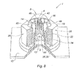
- the luminaire 1 may comprise a printed circuit 13, for example of the PCB or MCPCB type, supporting and electrically connecting the light sources, and the support 12 can be adapted to support this printed circuit, as can be seen on the figure 8 .
- the luminaire 1 may advantageously comprise a heat sink 20 for dissipating the heat generated by the luminaire 1 during operation.
- a heat sink 20 for dissipating the heat generated by the luminaire 1 during operation.
- the rotating member 18 advantageously comprises a first thread 22 and the luminaire 1 comprises a second thread 24 intended to cooperate with the first thread 22 to move the bearing surface 14.
- the second thread 24 may be provided either on the support 12 or on a part 25 attached to the support 12.
- the rotating member 18 advantageously comprises a first abutment surface 26 and a second abutment surface 28 on which are intended to bear two faces of a removable tool (not shown) or the fingers of a user.
- the first abutment surface 26 and the second abutment surface 28 may be substantially diametrically opposed.
- the first abutment surface 26 and the second abutment surface 28 may correspond to the inner wall of a hole 29 formed on an upper face of the rotational member 18. If necessary, a tool comprising two arms shaped to enter these holes makes it possible to exert a torque intended to rotate the rotation member 18 to deform the optics 4.
- first abutment surface 26 and the second abutment surface 28 may correspond to tab faces projecting from an upper surface of the rotational member 18.
- first abutment surface 26 and the second abutment surface 28 may correspond to flats of the rotating member 18.
- the lateral surface 8 may advantageously be of conical or frustoconical shape.
- the opening delimited by the bearing surface 14 has a diameter of dimension between a minimum diameter of the conical or frustoconical lateral surface 8 and a maximum diameter of the conical or frustoconical lateral surface 8.
- the lateral surface 8 may have a progressive widening towards the support 12. Although this is not shown, the lateral surface 8 may alternatively have a progressive widening in the direction of the exit surface 6, moving away from the support 12 .
- the optic 4 may comprise a recess 30 around which the support surface 14 extends. This recess 30 is formed inside the optic 4.
- the recess 30 may have a substantially parabolic shape.
- the light source 2 is advantageously arranged inside a cavity formed by this recess 30 and a face of the support 12 against which optics 4 is supported.
- the optic 4 may in fact comprise a bearing surface 32 bearing against the support 12.
- the surface 32 may be fixed to the support 12.
- the optic 4 comprises a circumferential groove 34 extending on a periphery 36 of the lateral surface 8.
- the lateral surface 8 therefore extends between the perimeter 10 of the outlet surface 6 and the circumferential groove 34.
- the groove 32 may have a V-shaped cross section. The opening of this groove 32 may be oriented opposite the support; in other words, the bottom of the groove 32 can be oriented towards the support 12.
- the bearing surface 14 is an inner surface of the rotating member 18, which can be located at the end of a radial portion 19 extending radially from a lateral portion 21 provided with the first thread 22.
- the user rotates the rotating member 18, for example by means of the abutment surfaces 26, 28. Due to this rotation, the first and second threads 22, 24 cooperate and cause a displacement in translation of the rotating member 18, in a direction substantially parallel to the optical axis and perpendicular to the support 12.
- the surface 14 support, located on the rotating member 18, is also translated. As the bearing surface 14 is translated, the radial support that the bearing surface 14 exerts on the optic 4 increases, in particular because of the conical shape of the lateral surface 8, which causes the deformation of the optic 4 and consequently the deformation of the exit surface 6. This changes the angle of a beam of light emitted at the output of luminaire 1.
- the luminaire 1 comprises an interposition piece 38 interposed between the rotation member 8 and the optic 4, and this interposition piece 38 comprises the support surface 14.
- This second embodiment therefore differs from the first embodiment of the figure 7 in that the rotating member 18 is not in direct contact with the optic 4.
- the luminaire 1 according to this second embodiment may comprise all or part of the other characteristics of the luminaire 1 according to the embodiment of FIG. realization of the figure 7 .
- the interposing member 38 advantageously comprises a plurality of elastic flexible teeth 40 separated from each other by cutouts 42 and arranged around and in abutment with the lateral surface 8 of the optics 4.
- the rotating member 18 comprises a friction surface 44 intended to bear against each tooth 40.
- the friction surface 44 is for example an inner surface of the rotating member 18, which can be located at the end of the radial portion 19 extending radially from the lateral portion 21 provided with the first thread 22. This friction surface 44 may be of conical shape.
- Each tooth 40 comprises an inner face 46 bearing against the lateral surface 8 of the optic 4, the inner faces 46 of the teeth forming the bearing surface 14.
- Each tooth 40 comprises an outer face 48 against which is intended to abut the friction surface 44.
- This outer face 48 may be conically shaped, or inclined relative to the optical axis, so that the translation of the rotating member 18 parallel to the optical axis causes, by friction of the surface 44 of friction against the faces 48, flexion of the teeth 40.
- the second thread 24 may be located on the interposition piece 38.
- the interposition piece 38 may be fixed on the support 12.
- the user rotates the rotating member 18, for example by means of the abutment surfaces 26, 28. Due to this rotation, the first and second threads 22, 24 cooperate and cause a displacement in translation of the rotating member 18, in a direction substantially parallel to the optical axis and perpendicular to the support 12.
- the friction surface 44 rubs against the outer face of the teeth 40 and, because of the conical shape of this outer face and / or the conical shape of the friction surface 44, the teeth 40 are radially plated against the optic 4.
- the optic 4 is deformed, so that its outlet surface 6 is also deformed. This changes the angle of a beam of light emitted at the output of luminaire 1.
Abstract
Ce luminaire (1) comprend une source (2) lumineuse, une optique (4) déformable, l'optique (4) comprenant une surface (6) de sortie destinée à la sortie de la lumière émise par la source (2) lumineuse hors du luminaire (1), et une surface (8) latérale s'étendant depuis la surface (6) de sortie. Le luminaire (1) comprend en outre des moyens de déformation de l'optique (4). Les moyens de déformation comprennent une surface (14) d'appui, mobile par rapport à la surface (8) latérale, et destinée à venir en appui contre la surface (8) latérale. La surface (14) d'appui délimite une ouverture en-travers de laquelle s'étend une portion de l'optique (4), et les moyens de déformation comprennent un organe (18) de rotation destiné à déplacer la surface (14) d'appui par rapport à la surface (8) latérale, de sorte que la surface (14) d'appui appuie contre la surface (8) latérale pour déformer la surface (6) de sortie.This luminaire (1) comprises a light source (2), a deformable optic (4), the optic (4) comprising an output surface (6) intended for the output of the light emitted by the light source (2) out of the luminaire (1), and a lateral surface (8) extending from the exit surface (6). The luminaire (1) further comprises means for deformation of the optics (4). The deformation means comprise a support surface (14) movable with respect to the lateral surface (8) and intended to bear against the lateral surface (8). The bearing surface (14) delimits an opening through which a portion of the optic (4) extends, and the deformation means comprise a rotational member (18) for moving the surface (14). resting with respect to the lateral surface (8) so that the bearing surface (14) bears against the lateral surface (8) to deform the exit surface (6).
Description
La présente invention concerne un luminaire à photométrie ajustable.The present invention relates to a luminaire with adjustable photometry.
Les luminaires à photométrie variable comprennent traditionnellement une source lumineuse, une optique déformable et des moyens pour déformer cette optique. La déformation de l'optique modifie, en sortie du luminaire, l'angle du faisceau de lumière émis par la source lumineuse, par exemple en élargissant l'angle de ce faisceau ou en diminuant l'angle de ce faisceau.Variable photometric luminaires traditionally comprise a light source, a deformable optic and means for deforming this optic. The distortion of the optics modifies, at the output of the luminaire, the angle of the light beam emitted by the light source, for example by widening the angle of this beam or by reducing the angle of this beam.
Selon le document de brevet
Selon le document de brevet
Les solutions traditionnelles pour déformer une optique reposent cependant sur l'application d'un champ électrique ou électromagnétique, et peuvent être par conséquent sensibles aux conditions de l'environnement extérieur, ce qui peut altérer la stabilité du réglage de la photométrie. Ce réglage peut aussi être altéré du fait de la chaleur générée par le luminaire en fonctionnement, cette chaleur pouvant provoquer la dilatation de composants en contact avec l'optique.Traditional solutions for deforming optics, however, rely on the application of an electric or electromagnetic field, and can therefore be sensitive to the conditions of the external environment, which can alter the stability of the adjustment of the photometry. This setting can also be altered due to the heat generated by the luminaire in operation, this heat can cause the expansion of components in contact with the optics.
Les solutions traditionnelles sont en outre parfois encombrantes, compte-tenu de la quantité ou de l'agencement des composants utilisés pour déformer l'optique. Elles peuvent aussi être coûteuses.Traditional solutions are also sometimes cumbersome, given the amount or arrangement of components used to deform the optics. They can also be expensive.
Aussi la présente invention vise à pallier tout ou partie de ces inconvénients en proposant un luminaire à photométrie ajustable, économique, compact, et offrant la possibilité de maîtriser avec précision et de façon stable la déformation de l'optique, donc le réglage de la photométrie en sortie du luminaire.Also the present invention aims to overcome all or part of these disadvantages by providing an adjustable photometric light, economic, compact, and offering the ability to control accurately and stably the deformation of the optics, so the adjustment of photometry at the output of the luminaire.
A cet effet, la présente invention a pour objet un luminaire à photométrie ajustable, comprenant une source lumineuse, une optique déformable, l'optique comprenant une surface de sortie, destinée à la sortie de la lumière émise par la source lumineuse hors du luminaire, et une surface latérale s'étendant depuis la surface de sortie, le luminaire comprenant en outre des moyens de déformation de l'optique, les moyens de déformation comprenant une surface d'appui mobile par rapport à la surface latérale, et destinée à venir en appui contre la surface latérale, la surface d'appui délimitant une ouverture en-travers de laquelle s'étend une portion de l'optique, et les moyens de déformation comprenant un organe de rotation destiné à déplacer la surface d'appui par rapport à la surface latérale, de sorte que la surface d'appui appuie contre la surface latérale pour déformer la surface de sortie.For this purpose, the subject of the present invention is a luminaire with adjustable photometry, comprising a light source, a deformable optic, the optic comprising an exit surface, intended for the output of the light emitted by the light source from the luminaire, and a lateral surface extending from the exit surface, the luminaire further comprising optical deformation means, the deformation means comprising a movable support surface by relative to the lateral surface, and intended to abut against the lateral surface, the bearing surface delimiting an opening through which extends a portion of the optic, and the deformation means comprising a rotational member for moving the bearing surface with respect to the lateral surface, so that the bearing surface bears against the lateral surface to deform the exit surface.
Ainsi, le luminaire selon l'invention offre une solution mécanique de déformation de l'optique par contact et déplacement de la surface d'appui et d'un organe de rotation, ce qui limite la sensibilité aux conditions de l'environnement extérieur.Thus, the luminaire according to the invention offers a mechanical solution of deformation of the optics by contact and displacement of the bearing surface and a rotation member, which limits the sensitivity to the conditions of the external environment.
De plus, l'ouverture délimitée par la surface d'appui et à travers laquelle s'étend l'optique assure une compacité améliorée.In addition, the opening defined by the support surface and through which the optics extends provides improved compactness.
Selon un mode de réalisation préféré, l'organe de rotation comprend un premier filetage et le luminaire comprend un deuxième filetage destiné à coopérer avec le premier filetage pour déplacer la surface d'appui.According to a preferred embodiment, the rotation member comprises a first thread and the luminaire comprises a second thread intended to cooperate with the first thread to move the bearing surface.
Ces caractéristiques permettent un déplacement précis de la surface d'appui, donc un réglage fin de la déformation de l'optique, indépendamment de l'environnement extérieur.These characteristics allow a precise displacement of the bearing surface, thus a fine adjustment of the deformation of the optics, independently of the external environment.
De manière avantageuse, l'organe de rotation comprend une première surface de butée et une deuxième surface de butée sur lesquelles sont destinés à prendre appui deux faces d'un outil amovible ou des doigts d'un utilisateur.Advantageously, the rotation member comprises a first abutment surface and a second abutment surface on which are intended to bear two faces of a removable tool or the fingers of a user.
Ainsi, le luminaire comprend des moyens exclusivement mécaniques de déformation de l'optique.Thus, the luminaire comprises exclusively mechanical means of deformation of the optics.
Selon une caractéristique avantageuse, la surface latérale est de forme conique ou tronconique.According to an advantageous characteristic, the lateral surface is of conical or frustoconical shape.
Ainsi, la déformation de l'optique est maximale pour un déplacement minimal de la surface d'appui. Cela augmente la sensibilité du réglage de la déformation de la surface de sortie, et réduit donc la course nécessaire de l'organe de rotation, ce qui permet une meilleure compacité.Thus, the distortion of the optics is maximum for a minimal displacement of the support surface. This increases the sensitivity of the adjustment of the deformation of the output surface, and therefore reduces the necessary stroke of the rotator, which allows a better compactness.
Selon un mode de réalisation avantageux, l'optique comprend une face inférieure présentant un évidement.According to an advantageous embodiment, the optic comprises a lower face having a recess.
Cela facilite la déformation de l'optique, donc la sensibilité du réglage et la compacité du luminaire.This facilitates the deformation of the optics, thus the sensitivity of the adjustment and the compactness of the luminaire.
Avantageusement, la source lumineuse est agencée à l'intérieur ou en regard d'une cavité formée par l'évidement.Advantageously, the light source is arranged inside or facing a cavity formed by the recess.
Cette caractéristique offre en plus l'avantage d'un encombrement limité.This feature also offers the advantage of limited space.
Selon une forme d'exécution avantageuse, l'optique comprend une rainure circonférentielle s'étendant sur un pourtour de la surface latérale.According to an advantageous embodiment, the optic comprises a circumferential groove extending around a periphery of the lateral surface.
Cette caractéristique augmente la sensibilité de déformation de l'optique.This feature increases the distortion sensitivity of the optics.
Selon un mode de réalisation avantageux, la surface d'appui est agencée sur l'organe de rotation.According to an advantageous embodiment, the bearing surface is arranged on the rotation member.
Cette caractéristique limite le nombre de composants mécaniques, si bien que le luminaire est économique et présente un encombrement limité.This feature limits the number of mechanical components, so that the luminaire is economical and has a small footprint.
Selon une autre possibilité, le luminaire comprend une pièce d'interposition interposée entre l'organe de rotation et l'optique.According to another possibility, the luminaire comprises an interposition piece interposed between the rotation member and the optics.
Cela limite avantageusement l'usure de l'optique, car l'organe de rotation ne frotte pas directement contre l'optique.This advantageously limits the wear of the optics, because the rotation member does not rub directly against the optics.
Avantageusement, la pièce d'interposition comprend une pluralité de dents flexibles agencées autour et en appui contre l'optique, et l'organe de rotation comprend une surface de frottement destinée venir en appui contre les dents pour faire fléchir les dents lors d'une rotation de l'organe de rotation.Advantageously, the interposition piece comprises a plurality of flexible teeth arranged around and in abutment with the optics, and the rotational member comprises a friction surface intended to bear against the teeth in order to bend the teeth during a rotation of the rotation member.
Ainsi, cela provoque une déformation de la surface de sortie de l'optique déformable.Thus, this causes a deformation of the output surface of the deformable optics.
L'avantage de ces caractéristiques est un effet progressif dans la déformation de l'optique. En effet, le déplacement de la surface de frottement le long des dents provoque un effet levier qui nécessite un couple de plus en plus important au fur et à mesure de la rotation de l'organe de rotation.The advantage of these characteristics is a progressive effect in the deformation of the optics. Indeed, the displacement of the friction surface along the teeth causes a lever effect which requires a torque increasing in importance as the rotation of the rotation member.
D'autres caractéristiques et avantages de la présente invention ressortiront clairement de la description ci-après d'un mode particulier de réalisation, donné à titre d'exemple non limitatif, en référence aux dessins annexés dans lesquels :
- Les
figures 1 et 2 sont des vues en perspective d'un luminaire selon un mode de réalisation de l'invention, - Les
figures 3 et 4 sont des vues de dessus des luminaires respectivement représentés sur lesfigures 1 et 2 , - La
figure 5 est une vue de dessus d'une partie d'un luminaire selon un mode de réalisation de l'invention, - La
figure 6 est une vue de côté d'une partie d'un luminaire selon un mode de réalisation de l'invention, - La
figure 7 est une vue en coupe selon la ligne I - I de lafigure 5 , - La
figure 8 est une vue en perspective et coupe partielle d'un luminaire selon un deuxième mode de réalisation de l'invention.
- The
Figures 1 and 2 are perspective views of a luminaire according to an embodiment of the invention, - The
Figures 3 and 4 are top views of the luminaires respectively shown on theFigures 1 and 2 , - The
figure 5 is a view from above of a part of a luminaire according to one embodiment of the invention, - The
figure 6 is a side view of part of a luminaire according to an embodiment of the invention, - The
figure 7 is a sectional view along the line I - I of thefigure 5 , - The
figure 8 is a perspective view and partial section of a luminaire according to a second embodiment of the invention.
La
Le luminaire 1 comprend une source 2 lumineuse, visible sur la
L'optique 4 comprend une surface 6 de sortie qui est destinée à la sortie de la lumière émise par la source 2 lumineuse hors du luminaire 1. La déformation de l'optique 4 permet la déformation de cette surface 6 de sortie, ce qui permet de modifier l'angle du faisceau de lumière émis en sortie du luminaire 1.The
L'optique 4 comprend également une surface 8 latérale. La surface 8 latérale s'étend depuis un pourtour 10 de la surface 6 de sortie. Le pourtour 10 de la surface 6 de sortie peut être sensiblement circulaire.The optic 4 also includes a
Le luminaire 1 comprend par ailleurs un support 12, destiné à supporter la source 2 lumineuse et/ou l'optique 4.The
Le luminaire 1 comprend aussi des moyens de déformation de l'optique 4. Les moyens de déformation de l'optique 4 comprennent une surface 14 d'appui, mobile par rapport au support 12. La surface 14 d'appui est destinée à venir en appui contre la surface 8 latérale. La surface 14 d'appui délimite en outre une ouverture 16 en-travers de laquelle s'étend une portion de l'optique 4. La surface 14 d'appui peut être sensiblement cylindriqueThe
Les moyens de déformation comprennent également un organe 18 de rotation, comme une bague filetée. L'organe 18 de rotation est mobile en rotation autour d'un axe de rotation et est destiné, du fait de sa rotation, à déplacer la surface 14 d'appui par rapport à la surface 8 latérale, de sorte que la surface 14 d'appui appuie contre la surface 8 latérale pour déformer l'optique 4 et par conséquent la surface 6 de sortie.The deformation means also comprise a rotating
En se déplaçant, la surface 14 d'appui peut serrer la portion de l'optique 4 s'étendant en-travers de l'ouverture 16. Ainsi, c'est une compression essentiellement radiale qui permet la déformation de l'optique 4.By moving, the
Comme cela est visible sur les différentes figures, les moyens de déformation sont des moyens exclusivement mécaniques de déformation. Autrement dit, aucun champ électrique ou électromagnétique n'est nécessaire à la déformation de l'optique.As can be seen in the various figures, the deformation means are exclusively mechanical means of deformation. In other words, no electric or electromagnetic field is necessary for deformation of the optics.
On notera que l'optique 4 peut être avantageusement une optique solide élastique. L'optique 4 peut être en polycarbonate, translucide ou transparent. Par ailleurs, l'optique 4 peut être une pièce de révolution.It will be noted that the
L'optique 4 peut être une lentille, notamment une lentille convergente ou divergente.The
La surface 8 latérale peut le cas échéant s'étendre autour d'un axe de révolution de l'optique 4, qui peut être confondu avec un axe optique de l'optique 4.The
L'organe 18 de rotation est mobile en rotation par rapport au support 12, par exemple autour d'un axe sensiblement perpendiculaire au support 12, un axe de révolution de l'optique 4, et/ou l'axe optique de l'optique 4, ces trois axes pouvant être confondus.The rotating
Plus particulièrement, l'organe 18 de rotation peut être en liaison hélicoïdale avec le support 12, c'est-à-dire mobile en rotation par rapport au support autour d'un axe, notamment l'axe optique ou un axe perpendiculaire au support 12, et mobile en translation par rapport au support le long de cet axe.More particularly, the rotating
Le support 12 est destiné à supporter la source 2 lumineuse. Le luminaire 1 peut bien entendu comprendre plusieurs sources 2 lumineuses. La ou les sources 2 lumineuses peuvent correspondre à des diodes électroluminescentes (LED selon l'acronyme anglais).The
Le support 12 peut être sensiblement plan ; il peut se présenter sous la forme d'une plaque. Le support 12 peut correspondre à un circuit imprimé, du type PCB ou MCPCB, destiné à supporter et à relier électriquement la ou les sources 2 lumineuses. Alternativement, le luminaire 1 peut comprendre un circuit imprimé 13, par exemple du type PCB ou MCPCB, supportant et reliant électriquement les sources lumineuses, et le support 12 peut être adapté pour supporter ce circuit imprimé, comme cela est visible sur la
Le luminaire 1 peut avantageusement comprendre un dissipateur 20 thermique pour dissiper la chaleur générée par le luminaire 1 en fonctionnement. Ainsi, cela limite la dilatation de l'organe 18 de rotation ou de la surface 14 d'appui du fait de cette chaleur, ce qui permet de maintenir un réglage stable d'un état de déformation de l'optique 4, en particulier de la surface 6 de sortie.The
L'organe 18 de rotation comprend avantageusement un premier filetage 22 et le luminaire 1 comprend un deuxième filetage 24 destiné à coopérer avec le premier filetage 22 pour déplacer la surface 14 d'appui. Le deuxième filetage 24 peut être ménagé soit sur le support 12, soit sur une pièce 25 rapportée sur le support 12.The rotating
L'organe 18 de rotation comprend avantageusement une première surface 26 de butée et une deuxième surface 28 de butée sur lesquelles sont destinés à prendre appui deux faces d'un outil amovible (non représenté) ou les doigts d'un utilisateur.The rotating
La première surface 26 de butée et la deuxième surface 28 de butée peuvent être sensiblement diamétralement opposées.The
Comme cela est illustré sur les
Comme cela est illustré sur les
Comme cela est illustré sur la
Comme on peut le voir sur la
L'ouverture délimitée par la surface 14 d'appui présente un diamètre de dimension comprise entre un diamètre minimum de la surface 8 latérale conique ou tronconique et un diamètre maximum de la surface 8 latérale conique ou tronconique.The opening delimited by the bearing
Selon le mode de réalisation représenté sur les
Comme on peut le voir sur la
La source 2 lumineuse est agencée avantageusement à l'intérieur d'une cavité formée par cet évidement 30 et une face du support 12 contre laquelle appuie l'optique 4.The
L'optique 4 peut en effet comprendre une surface 32 de maintien en appui contre le support 12. La surface 32 peut être fixée au support 12.The
Comme cela est visible sur la
Selon un premier mode de réalisation, visible sur la
Le fonctionnement du luminaire 1 selon le mode de réalisation de la
L'utilisateur fait pivoter l'organe 18 de rotation, par exemple au moyen des surfaces 26, 28 de butée. Du fait de cette rotation, les premier et deuxième filetages 22, 24 coopèrent et entraînent un déplacement en translation de l'organe 18 de rotation, selon une direction sensiblement parallèle à l'axe optique et perpendiculaire au support 12. La surface 14 d'appui, située sur l'organe 18 de rotation, se translate également. Au fur et à mesure que la surface 14 d'appui se translate, l'appui radial que la surface 14 d'appui exerce sur l'optique 4 augmente, notamment en raison de la forme conique de la surface 8 latérale, ce qui provoque la déformation de l'optique 4 et par conséquent la déformation de la surface 6 de sortie. Cela modifie l'angle d'un faisceau de lumière émis en sortie du luminaire 1.The user rotates the rotating
Selon un deuxième mode de réalisation, visible sur la
Ce deuxième mode de réalisation diffère donc du premier mode de réalisation de la
L'organe 38 d'interposition comprend avantageusement une pluralité de dents 40 flexibles élastiques séparées les unes des autres par des découpes 42 et agencées autour et en appui contre la surface 8 latérale de l'optique 4.The interposing member 38 advantageously comprises a plurality of elastic
Selon le mode de réalisation de la
Chaque dent 40 comprend une face 46 intérieure en appui contre la surface 8 latérale de l'optique 4, les faces 46 intérieures des dents formant la surface 14 d'appui.Each
Chaque dent 40 comprend une face 48 extérieure contre laquelle est destinée à venir en appui la surface 44 de frottement. Cette face 48 extérieure peut être de forme conique, ou inclinée par rapport à l'axe optique, pour que la translation de l'organe 18 de rotation parallèlement à l'axe optique provoque, par frottement de la surface 44 de frottement contre les faces 48 extérieures, une flexion des dents 40.Each
Le deuxième filetage 24 peut être situé sur la pièce 38 d'interposition. La pièce 38 d'interposition peut être fixée sur le support 12.The
Le fonctionnement du luminaire 1 selon le mode de réalisation de la
L'utilisateur fait pivoter l'organe 18 de rotation, par exemple au moyen des surfaces 26, 28 de butée. Du fait de cette rotation, les premier et deuxième filetages 22, 24 coopèrent et entraînent un déplacement en translation de l'organe 18 de rotation, selon une direction sensiblement parallèle à l'axe optique et perpendiculaire au support 12. La surface 44 de frottement frotte contre la face extérieure des dents 40 et, du fait de la forme conique de cette face extérieure et/ou de la forme conique de la surface 44 de frottement, les dents 40 sont plaquées radialement contre l'optique 4. La face intérieure des dents 40, formant la surface 14 d'appui, presse la surface 8 latérale de l'optique 4. Ainsi, l'optique 4 se déforme, si bien que sa surface 6 de sortie se déforme aussi. Cela modifie l'angle d'un faisceau de lumière émis en sortie du luminaire 1.The user rotates the rotating
Bien entendu, l'invention n'est nullement limitée au mode de réalisation décrit ci-dessus, ce mode de réalisation n'ayant été donné qu'à titre d'exemple. Des modifications sont possibles, notamment du point de vue de la constitution des divers éléments ou par la substitution d'équivalents techniques, sans sortir pour autant du domaine de protection de l'invention.Of course, the invention is not limited to the embodiment described above, this embodiment having been given as an example. Modifications are possible, particularly from the point of view of the constitution of the various elements or by the substitution of technical equivalents, without departing from the scope of protection of the invention.
Claims (10)
Applications Claiming Priority (1)
| Application Number | Priority Date | Filing Date | Title |
|---|---|---|---|
| FR1452799A FR3019265B1 (en) | 2014-03-31 | 2014-03-31 | ADJUSTABLE PHOTOMETRY LUMINAIRE |
Publications (1)
| Publication Number | Publication Date |
|---|---|
| EP2927574A1 true EP2927574A1 (en) | 2015-10-07 |
Family
ID=51014474
Family Applications (1)
| Application Number | Title | Priority Date | Filing Date |
|---|---|---|---|
| EP15161710.7A Withdrawn EP2927574A1 (en) | 2014-03-31 | 2015-03-30 | Luminaire with variable photometric characteristics |
Country Status (2)
| Country | Link |
|---|---|
| EP (1) | EP2927574A1 (en) |
| FR (1) | FR3019265B1 (en) |
Cited By (1)
| Publication number | Priority date | Publication date | Assignee | Title |
|---|---|---|---|---|
| WO2020025427A1 (en) * | 2018-07-31 | 2020-02-06 | Schreder S.A. | Lighting device with adjustable light distribution |
Citations (5)
| Publication number | Priority date | Publication date | Assignee | Title |
|---|---|---|---|---|
| US20060062000A1 (en) | 2004-09-20 | 2006-03-23 | Peterson Mark D | Luminaire having a deformable reflector well |
| US20060072181A1 (en) | 2002-12-30 | 2006-04-06 | Koninklijke Philips Electronics N.V. | Optical device comprising a polymer actuator |
| US20110299287A1 (en) * | 2010-06-07 | 2011-12-08 | Eiko (Pacific) Ltd. | Focusing mechanism for led spot lamp |
| WO2012027851A1 (en) * | 2010-09-02 | 2012-03-08 | Optotune Ag | Illumination source with variable divergence |
| US20120147606A1 (en) * | 2010-12-09 | 2012-06-14 | Tsun-Hung Huang | led lamp capable of adjusting a beam spread thereof |
-
2014
- 2014-03-31 FR FR1452799A patent/FR3019265B1/en active Active
-
2015
- 2015-03-30 EP EP15161710.7A patent/EP2927574A1/en not_active Withdrawn
Patent Citations (5)
| Publication number | Priority date | Publication date | Assignee | Title |
|---|---|---|---|---|
| US20060072181A1 (en) | 2002-12-30 | 2006-04-06 | Koninklijke Philips Electronics N.V. | Optical device comprising a polymer actuator |
| US20060062000A1 (en) | 2004-09-20 | 2006-03-23 | Peterson Mark D | Luminaire having a deformable reflector well |
| US20110299287A1 (en) * | 2010-06-07 | 2011-12-08 | Eiko (Pacific) Ltd. | Focusing mechanism for led spot lamp |
| WO2012027851A1 (en) * | 2010-09-02 | 2012-03-08 | Optotune Ag | Illumination source with variable divergence |
| US20120147606A1 (en) * | 2010-12-09 | 2012-06-14 | Tsun-Hung Huang | led lamp capable of adjusting a beam spread thereof |
Cited By (4)
| Publication number | Priority date | Publication date | Assignee | Title |
|---|---|---|---|---|
| WO2020025427A1 (en) * | 2018-07-31 | 2020-02-06 | Schreder S.A. | Lighting device with adjustable light distribution |
| BE1026500B1 (en) * | 2018-07-31 | 2020-03-02 | Schreder Sa | Lighting device with adjustable light distribution |
| US11320105B2 (en) | 2018-07-31 | 2022-05-03 | Schreder S.A. | Lighting device with adjustable light distribution |
| AU2019315657B2 (en) * | 2018-07-31 | 2023-04-06 | Schreder S.A. | Lighting device with adjustable light distribution |
Also Published As
| Publication number | Publication date |
|---|---|
| FR3019265A1 (en) | 2015-10-02 |
| FR3019265B1 (en) | 2021-01-22 |
Similar Documents
| Publication | Publication Date | Title |
|---|---|---|
| EP1182396A1 (en) | Lamp based on LEDs' light emission | |
| EP3104074B1 (en) | Positioning device of a led support on a support element and illumination or signalisation device comprising such a device | |
| FR3037128A1 (en) | VEHICLE LAMP | |
| EP2966344B1 (en) | Optical module with lens for motor vehicle projector headlamp | |
| FR2850448A1 (en) | Portable light source using electro-luminescent diodes, uses screen with integral Fresnel lenses which can be moved over front of diode to adjust spread of beam from diode | |
| FR3062612A1 (en) | OPTICAL MODULE FOR MOTOR VEHICLE AND LATCHING IN THE POSITION OF A COMPONENT OF THE MODULE BY AN ELASTICALLY DEFORMABLE LOADING MEMBER | |
| EP2846079B1 (en) | Lighting module for an illumination and/or signalling device | |
| FR3071452A1 (en) | VEHICLE FIRE | |
| EP2927574A1 (en) | Luminaire with variable photometric characteristics | |
| EP1589587A1 (en) | Package for optical semiconductor with compressible control means | |
| FR2535016A1 (en) | FRONT LIGHTING DEVICE FOR BICYCLES OR THE LIKE | |
| EP3300952A1 (en) | Variable interior lighting device for vehicle | |
| EP3507543A1 (en) | Medical illumination device with leds oriented by tabs pre-cut in a printed circuit board | |
| FR2897120A1 (en) | Pivot for variable-angle turbine compressor blade has one or more flat surfaces to co-operate with matching surfaces in angle adjustment lever | |
| EP2535785A1 (en) | Device for controlling a household appliance | |
| FR3056684A1 (en) | VEHICLE FIRE AND VEHICLE EXTERIOR RETROVISION DEVICE | |
| FR2705710A3 (en) | Curtain wall and assembly for erecting it | |
| CH654655A5 (en) | Laser site for a firearm | |
| EP2884159A1 (en) | Luminaire with adjustable photometry | |
| EP2772680B1 (en) | Rotary electric lighting apparatus | |
| FR2889731A1 (en) | LIGHTING DEVICE WITH VARIABLE OPENING OF THE LIGHT BEAM | |
| EP2639492B1 (en) | Portable electric lamp with compact housing mounted angularly movable | |
| EP1764836B1 (en) | Structure for mounting a mobile objective over an optical sensor | |
| FR3084756A1 (en) | DEVICE FOR TAKING A PRODUCT PLAN | |
| FR3006744A1 (en) | OPTICAL DEVICE, IN PARTICULAR FOR A DEVICE FOR LIGHTING AND / OR SIGNALING A MOTOR VEHICLE, AND LIGHTING AND / OR SIGNALING DEVICE COMPRISING SUCH A DEVICE |
Legal Events
| Date | Code | Title | Description |
|---|---|---|---|
| PUAI | Public reference made under article 153(3) epc to a published international application that has entered the european phase |
Free format text: ORIGINAL CODE: 0009012 |
|
| AK | Designated contracting states |
Kind code of ref document: A1 Designated state(s): AL AT BE BG CH CY CZ DE DK EE ES FI FR GB GR HR HU IE IS IT LI LT LU LV MC MK MT NL NO PL PT RO RS SE SI SK SM TR |
|
| AX | Request for extension of the european patent |
Extension state: BA ME |
|
| STAA | Information on the status of an ep patent application or granted ep patent |
Free format text: STATUS: THE APPLICATION IS DEEMED TO BE WITHDRAWN |
|
| 18D | Application deemed to be withdrawn |
Effective date: 20160408 |