EP2924973A2 - Optoelektronische vorrichtung und verfahren zum justieren - Google Patents
Optoelektronische vorrichtung und verfahren zum justieren Download PDFInfo
- Publication number
- EP2924973A2 EP2924973A2 EP15155872.3A EP15155872A EP2924973A2 EP 2924973 A2 EP2924973 A2 EP 2924973A2 EP 15155872 A EP15155872 A EP 15155872A EP 2924973 A2 EP2924973 A2 EP 2924973A2
- Authority
- EP
- European Patent Office
- Prior art keywords
- adaptive lens
- image
- image feature
- lens
- image sensor
- Prior art date
- Legal status (The legal status is an assumption and is not a legal conclusion. Google has not performed a legal analysis and makes no representation as to the accuracy of the status listed.)
- Granted
Links
Images


Classifications
-
- G—PHYSICS
- G02—OPTICS
- G02B—OPTICAL ELEMENTS, SYSTEMS OR APPARATUS
- G02B27/00—Optical systems or apparatus not provided for by any of the groups G02B1/00 - G02B26/00, G02B30/00
- G02B27/64—Imaging systems using optical elements for stabilisation of the lateral and angular position of the image
- G02B27/646—Imaging systems using optical elements for stabilisation of the lateral and angular position of the image compensating for small deviations, e.g. due to vibration or shake
- G02B27/648—Imaging systems using optical elements for stabilisation of the lateral and angular position of the image compensating for small deviations, e.g. due to vibration or shake for automatically maintaining a reference alignment, e.g. in self-levelling surveying instruments
-
- G—PHYSICS
- G02—OPTICS
- G02B—OPTICAL ELEMENTS, SYSTEMS OR APPARATUS
- G02B26/00—Optical devices or arrangements for the control of light using movable or deformable optical elements
- G02B26/004—Optical devices or arrangements for the control of light using movable or deformable optical elements based on a displacement or a deformation of a fluid
-
- H—ELECTRICITY
- H04—ELECTRIC COMMUNICATION TECHNIQUE
- H04N—PICTORIAL COMMUNICATION, e.g. TELEVISION
- H04N17/00—Diagnosis, testing or measuring for television systems or their details
- H04N17/002—Diagnosis, testing or measuring for television systems or their details for television cameras
-
- G—PHYSICS
- G01—MEASURING; TESTING
- G01V—GEOPHYSICS; GRAVITATIONAL MEASUREMENTS; DETECTING MASSES OR OBJECTS; TAGS
- G01V8/00—Prospecting or detecting by optical means
- G01V8/10—Detecting, e.g. by using light barriers
- G01V8/12—Detecting, e.g. by using light barriers using one transmitter and one receiver
-
- G—PHYSICS
- G01—MEASURING; TESTING
- G01V—GEOPHYSICS; GRAVITATIONAL MEASUREMENTS; DETECTING MASSES OR OBJECTS; TAGS
- G01V8/00—Prospecting or detecting by optical means
- G01V8/10—Detecting, e.g. by using light barriers
- G01V8/20—Detecting, e.g. by using light barriers using multiple transmitters or receivers
-
- G—PHYSICS
- G02—OPTICS
- G02B—OPTICAL ELEMENTS, SYSTEMS OR APPARATUS
- G02B1/00—Optical elements characterised by the material of which they are made; Optical coatings for optical elements
- G02B1/06—Optical elements characterised by the material of which they are made; Optical coatings for optical elements made of fluids in transparent cells
-
- G—PHYSICS
- G02—OPTICS
- G02B—OPTICAL ELEMENTS, SYSTEMS OR APPARATUS
- G02B3/00—Simple or compound lenses
- G02B3/12—Fluid-filled or evacuated lenses
Definitions
- the invention relates to an optoelectronic device with an adaptive lens according to the preamble of claim 1 and to a method for aligning such optoelectronic devices according to the preambles of claims 9, 10 and 11.
- the aim here is to align the optical system between the mounting points of the device and a desired illumination or viewing area, compensating for offset and tilt tolerances. If replacement of an optical system is required, this procedure must be repeated. When using several optical systems in parallel, for example in a multi-head camera with several camera modules, the mutual alignment must be ensured.
- optics are often provided, which are set sharply by means of a focus adjustment to a specific distance or distance range by adjusting the position of the lenses and thus the focal length of the transmitting or receiving optics electromechanically or optomechanically.
- Such solutions require a lot of space and also make high demands on the mechanical structure for precise adjustability, so that a given focal position is actually accepted.
- An alternative is the use of optics, in which not the cutting width, but directly the shape and thus the focal length of the lens itself is varied by means of a voltage control.
- gel or liquid lenses are used for this purpose.
- a silicone-like liquid is mechanically deformed by means of piezoelectric or inductive actuators.
- Liquid lenses for example, use the so-called electrowetting effect by arranging two immiscible liquids in a single chamber. When applying a control voltage, the two liquids change their surface tension in different ways, so that the inner interface of the liquids changes their curvature depending on the voltage.
- An optoelectronic sensor with focus adjustment based on liquid lenses is from the DE 10 2005 015 500 A1 or the DE 20 2006 017 268 U1 known. The focus adjustment allows adaptation to the scene, but does not replace adjustment.
- the device comprises an optic with an adaptive lens whose tilt can be changed by electronic control.
- the adaptive lens is preferably also adjustable in its focal length in order to set a focus position.
- tilting the adaptive lens tolerances can be compensated in a very simple manner. This can be manufacturing tolerances of the components themselves, ie batch fluctuations of light emitters, light receivers or optical elements. Another source are inaccuracies in the installation of the components in the device, which lead to assembly tolerances of the components to each other and to a housing. But mounting tolerances can also affect the attachment of the device at the place of use. Often the aim of the adjustment is that a lighting or field of view of the device has a specified geometry and orientation, that is, assumes a desired position, orientation and shape in the scene.
- the invention has the advantage that complex mechanical adjustment processes can be eliminated. This saves costs in design and for the implementation of the adjustment. Nevertheless, a very good adaptation is achieved.
- the tilting is a significant factor, since tilting tolerances in the focal plane lead to a large lateral offset.
- the adjustment unit preferably has a storage element in order to store a tilting position of the adaptive lens taught in the production process as an adjusted factory setting.
- a tilting position of the adaptive lens taught in the production process By adjusting the stored tilt position results in an adjusted device without mechanical adjustment options must be provided in their design or a complex adjustment process is required.
- an application-specific tilting and thus alignment is conceivable.
- the device is preferably designed as a camera with an image sensor as a light receiver. By tilting the adaptive lens image sensor and receiving optics are easily aligned with each other, and it is set a field of view of the camera.
- the adjustment unit is preferably designed to identify at least one image feature in a receptacle of the image sensor and to store it together with the position. Based on the image feature, the adjustment unit can check a once reached alignment. Primarily, however, serve the image feature and its position as a preparation for a later device replacement.
- the storage preferably takes place permanently, that is to say independently of the operation of the device, so that the data remain available even after a prolonged downtime or in the event of a defect. Also suitable is the storage in a higher-level control or on a removable medium.
- the adjustment unit is preferably designed to read in at least one image feature and one position of the image feature and to tilt the adaptive lens such that the image feature is located in a receptacle of the image sensor at the position.
- the read-in data are preferably those that a different device has generated and stored. This interchangeability is achieved by the replacement device automatically sets the identical field of view as the replaced device based on the at least one image feature. This preserves the entire physical field of view exchanged systems, without losing information, for example, by trimming the images to a smaller common field of view.
- At least two image sensors are provided, each of which is preceded by an optical system with an adaptive lens with variable tilt, wherein the viewing areas of the image sensors have an overlap region.
- the adjustment unit identifies at least one image feature in the overlap region and uses the image feature to align the fields of view of the image sensors by tilting at least one adaptive lens relative to one another.
- the individual fields of view are adjacent to each other and are aligned so that no lateral offset occurs. This can maximize the overall viewing area, with a very small overlap area.
- the image features or other image features outside the overlap area may also be stored for a replacement device as discussed above to allow for replacement of individual camera modules while maintaining alignment.
- the adaptive lens is preferably a liquid lens or a gel lens.
- Such lenses offer the desired adjustment options and are very compact and inexpensive.
- the tilting of such a lens does not necessarily mean a geometric tilting, but refers to the optical effect, which effectively corresponds to a tilt.
- the adaptive lens preferably has segmented drive elements in the direction of rotation.
- the control elements are, for example, segmented electrodes which control a liquid lens via the electrowetting effect.
- segmented actuators in particular piezo actuators, which locally change the pressure on a liquid and thereby bend a membrane differently on liquid, or which directly deform a gel-like substance of the lens. Due to the segmentation in the direction of rotation, a non-rotationally symmetrical influencing of the lens is made possible, which leads to the optical tilting.
- inventive method can be configured in a similar manner by further features and shows similar advantages. Such further features are exemplary, but not exhaustive, in which subclaims following the independent claims are described.
- the adaptive lens is tilted such that manufacturing tolerances and / or mounting tolerances are compensated.
- manufacturing tolerances and / or mounting tolerances are compensated.
- a method according to claim 10 relates to the replacement of a camera with an image sensor and an image sensor upstream receiving optics with an adaptive lens.
- a later possibly exchanged camera stores at least one image feature and its position with respect to its image sensor.
- the replacement device uses this information and ensures that the image feature is in the correct position. This ensures that the replacement device can take over its function in the same orientation.
- At least two cameras, each with an image sensor and an optical system arranged upstream of the image sensor, are aligned with an adaptive lens with variable tilt relative to one another.
- at least one image feature in an overlap region is identified, and the fields of view of the image sensors are aligned on the basis of the image feature by tilting at least one adaptive lens to each other.
- the result is an aligned total field of view of maximum size, for which a minimum overlap area is sufficient.
- FIG. 1 shows a schematic sectional view of an embodiment of an optoelectronic device 10 for detecting object information from a monitoring area 12.
- a receiving optical system 14 generates an image sensor 16, such as a CCD or CMOS chip, recordings of the monitoring area 12. The image data of these recordings are sent to an evaluation unit 18 passed.
- the receiving optical system 14 has an adaptive lens that can be tilted by electronic control of the evaluation unit 18. By tilting results in a variation of the field of view of the device 10.
- the principle of operation of the adaptive lens is described below with reference to FIGS. 4 to 6 explained in more detail.
- the image sensor 14 and the in FIG. 1 Simplifying receiving optical system 16 represented by the adaptive lens form an assembly which may have further optical elements (not shown), such as lenses, mirrors, diaphragms or filters. There is also the possibility that the device 10 has a plurality of adaptive lenses.
- the tilting of the adaptive lens of the receiving optics 16 is used in a learning process for adjustment.
- the evaluation unit 18 acts as an adjustment unit, which controls the adaptive lens in order to change its tilting position.
- tolerances of the components and their mutual arrangement can be reduced by external monitoring and targeted control of the adaptive lens. This can be done both in the factory during production and in the field for the specific application.
- the learned tilt position and the required control can be stored as a factory setting in a memory element. This makes it possible at any time to vary the tilt position of the adaptive lens and then return to the stored settings.
- the evaluation unit 18 of the original device ie the originally used device 10 stores at least one constantly available and reliably identifiable image feature 20 from the surveillance area 20 and its position within the field of view of the device 10 after completion of assembly or during operation in particular a part of a lighting pattern or a Light spot of its own light source, especially if no sufficient natural scene contrast or at least over a certain period of time constant scene area is expected.
- a target device or a target laser can be provided in the device 10, which is used to visualize a recording or reading area.
- the data stored by the original device is loaded to the image feature 20.
- the replacement device detects scene features and identifies the image feature 20 via a comparison of the scene features with the loaded data of the original sensor.
- By controlling the adaptive lens tilting of the field of view is performed until the image feature 20 is also for the replacement device at the intended location and thus its field of view at the same position as in the original device.
- FIG. 2 shows a further embodiment of the optoelectronic device 10. This embodiment differs from that in FIG. 1 shown embodiment in that here instead of a light receiver or image sensor 16, a light transmitter 22 and accordingly an adaptive lens is provided as part of a transmitting optical system 24 instead of the receiving optical system 14.
- a light transmitter 22 instead of a light transmitter 22
- an adaptive lens is provided as part of a transmitting optical system 24 instead of the receiving optical system 14.
- hybrid forms are again mentioned, in which both a light transmitter and a light receiver are provided, wherein an adaptive lens is provided at least in the transmission path or in the reception path.
- FIG. 3 shows another example of alignment by tilting adaptive lenses.
- the optoelectronic device 10 has a multiplicity of camera modules 10a-d whose monitoring areas or fields of view 12a-d complement each other to form a larger overall field of view and which, for example, are each constructed in the same way as the device 10 according to FIG. 1 ,
- not every camera module 10a-d has to have its own evaluation unit 18, which instead can be implemented superordinately or distributed almost arbitrarily.
- the camera modules 10a-d are connected to each other or by means of a higher-level control and can thus communicate with one another.
- the camera modules 10a-d arranged in parallel should be aligned with one another. Unaffected by this remains a possible adjustment of the camera modules 10a-d, as described above.
- the fields of view 12a-d are initially not aligned exactly with each other. This is in the middle of FIG. 3 shown.
- the conventional solution would be to tailor the common field of view to a central area illustrated by the dashed lines by software cutting. As a result, however, part of the possible field of view is lost.
- scene or image features in overlapping areas of the fields of view 12a-d are preferably identified and compared at the maximum focus distance.
- the alignment can be corrected by tilting the adaptive lenses of the camera modules 12a-d, resulting in the FIG. 3 Optimal alignment shown below with maximum size of the total field of view.
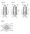
- FIGS. 4 and 5 show the adaptive lens of the receiving optics 14 and the transmitting optics 22 in an exemplary embodiment as a liquid lens 26 after the electrowetting effect.
- the operation is explained on the basis of this liquid lens 26, but the invention also encompasses other adaptive lenses, for example those with a liquid chamber and a membrane covering the same, the curvature of which is changed by pressure on the liquid, or lenses with a gel-like, optically permeable material an actuator is mechanically deformed.
- the actively tunable liquid lens 26 has two transparent, immiscible liquids 28, 30 with different refractive indices and the same density.
- the shape of the liquid-liquid boundary layer 32 between the two liquids 28, 30 is used for optical function.
- the actuation is based on the principle of electrowetting, which shows a dependence of the surface or interfacial tension on the applied electric field. Therefore, it is possible to change the shape of the boundary layer 32 and thus the optical properties of the liquid lens 26 by electrical control at a terminal 34, whereby corresponding voltages applied to an electrode 36.
- FIG. 4 first shows the longer known change in the focus properties of the liquid lens 26.
- Incident light is scattered at a concave boundary layer 32.
- FIG. 4b shows a neutral setting with flat boundary layer 32, while in Figure 4c the boundary layer is convex and thus bundles the incident light. It is clear that the refractive behavior can be finer graded by appropriate intermediate settings and, for example, a focal length can be set.
- the liquid lens 26 can also be influenced in its tilting. This will be in FIG. 5 illustrates and is based on non-rotationally symmetric voltages and thus electric fields. Accordingly, the boundary layer 32 is not rotationally symmetrical deformed, which is utilized for the tilting.
- FIG. 5a shows a tilt of the liquid lens 26 down
- FIG. 5b a rotationally symmetric adjustment without tilting for comparison
- FIG. 5c a tilt of the liquid lens 26 upwards.
- the direction of tilting respectively refers to the optical effect, that is, from which direction light is received or in which direction transmitted light is emitted.
- the tilting can each be superimposed on a focus.
- FIG. 6 shows a plan view of the liquid lens 26 to again explain the non-rotationally symmetrical control.
- the electrode 36 is segmented.
- additional connection 34b are required.
Abstract
Description
- Die Erfindung betrifft eine optoelektronische Vorrichtung mit einer adaptiven Linse nach dem Oberbegriff von Anspruch 1 sowie Verfahren zum Ausrichten derartiger optoelektronischer Vorrichtungen nach den Oberbegriffen von Anspruch 9, 10 und 11.
- Für eine reibungslose Funktion muss in optischen Systemen mit hohen Qualitätsanforderungen eine verlässliche Justierung gewährleistet werden. Das betrifft zum einen die Fertigung, wo während oder nach dem Zusammenbau die optischen Komponenten, wie Lichtquellen, Linsen, Filter oder Bildsensoren, zueinander ausgerichtet werden, um Toleranzen oder Chargenschwankungen auszugleichen. Die mechanische Justage erfordert zusätzliche Freiheitsgrade im Design, um überhaupt Verstellmöglichkeiten für die Ausrichtung zu bieten, und außerdem Betriebsmittel beziehungsweise Personalaufwand für die manuelle, halb- oder vollautomatische Durchführung der Justage. Dadurch werden die Herstellkosten erheblich erhöht.
- Die Justierung spielt zum anderen auch im Feld eine wichtige Rolle. Hier geht es darum, das optische System unter Ausgleich von Versatz- und Verkippungstoleranzen zwischen den Befestigungspunkten des Geräts und einem gewünschten Beleuchtungsbeziehungsweise Sichtbereich auszurichten. Wird ein Austausch eines optischen Systems erforderlich, muss dieser Vorgang wiederholt werden. Beim parallelen Einsatz mehrerer optischer Systeme, etwa in einer Multihead-Kamera mit mehreren Kameramodulen, ist für die gegenseitige Ausrichtung zu sorgen.
- Alternativ zu einer Ausrichtung ist bei Kamerasystemen auch denkbar, den Sichtbereich durch Bildverarbeitung zuzuschneiden, der sich dadurch jedoch verkleinert. Dies gilt entsprechend für die Parallelisierung mehrerer Kameramodule, wo ein Toleranzbereich als zusätzliche Überlappungsfläche vorgehalten werden kann, um ein lückenloses, aber wegen der zusätzlichen Überlappung verkleinertes Gesamtgesichtsfeld zu erhalten.
- In optischen Systemen ist häufig eine Optik vorgesehen, die mit Hilfe einer Fokusverstellung auf einen bestimmten Abstand oder Abstandsbereich scharf eingestellt wird, indem elektromechanisch oder optomechanisch die Position der Linsen und damit die Schnittweite der Sende- oder Empfangsoptik verstellt wird. Solche Lösungen erfordern viel Bauraum und stellen zudem hohe Ansprüche an den mechanischen Aufbau zur präzisen Einstellbarkeit, damit eine vorgegebene Fokuslage auch tatsächlich angenommen wird. Eine Alternative ist der Einsatz von Optiken, bei denen nicht die Schnittweite, sondern unmittelbar die Form und damit die Brennweite der Linse selbst mittels einer Spannungsansteuerung variiert wird. Insbesondere werden dafür Geloder Flüssiglinsen genutzt. Bei einer Gellinse wird eine silikonartige Flüssigkeit mittels piezoelektrischer oder induktiver Aktoren mechanisch deformiert. Flüssiglinsen nutzen beispielsweise den sogenannten Elektrobenetzungseffekt (electrowetting) aus, indem zwei nicht mischbare Flüssigkeiten in einer Kammer übereinander angeordnet werden. Bei Anlegen einer Steuerspannung ändern die beiden Flüssigkeiten ihre Oberflächenspannung in unterschiedlicher Weise, so dass die innere Grenzfläche der Flüssigkeiten spannungsabhängig ihre Krümmung verändert. Ein optoelektronischer Sensor mit Fokusverstellung auf Basis von Flüssiglinsen ist aus der
DE 10 2005 015 500 A1 oder derDE 20 2006 017 268 U1 bekannt. Die Fokusverstellung ermöglicht eine Anpassung an die Szenerie, ersetzt aber keine Justierung. - In Weiterbildung von Flüssiglinsen zur Fokusverstellung schlägt die
EP 2 071 367 A1 vor, auch die Verkippung der Flüssiglinse durch Anlegen unterschiedlicher Spannungen in Umlaufrichtung zu verändern. Um die Aufnahme verwackelter Bilder zu verhindern, wird dann die Eigenbewegung der Kamera ermittelt, und eine oder mehrere Linsen in der Kamera werden verkippt, um dieser Eigenbewegung entgegenzuwirken. Diese Bewegungskompensation basiert ebenfalls auf einer zuvor erfolgten Ausrichtung der Kamera in sich. Eine Ausrichtung bezüglich der Szenerie ist für eine handgehaltene Kamera ohnehin nicht festgeschrieben. - In der
DE 10 2005 015 500 A1 wird ein weiterer optoelektronischer Sensor mit einer Flüssiglinse offenbart, die durch einen asymmetrischen Rahmen oder unterschiedliche elektrische Potentiale an separaten Elektroden des Linsenrahmens in ihren Strahlformungseigenschaften asymmetrisch veränderbar ist. Das Dokument erläutert dann aber nicht, wozu das genutzt werden kann. - Es ist daher Aufgabe der Erfindung, die Justierung einer optoelektronischen Vorrichtung zu vereinfachen.
- Diese Aufgabe wird durch eine optoelektronische Vorrichtung nach Anspruch 1 und 6 sowie ein Verfahren nach den Ansprüchen 9, 10 und 11 gelöst. Die Vorrichtung umfasst eine Optik mit einer adaptiven Linse, deren Verkippung durch elektronische Ansteuerung verändert werden kann. Die adaptive Linse ist vorzugsweise auch in ihrer Brennweite verstellbar, um eine Fokuslage einzustellen. Durch das Verkippen der adaptiven Linse können auf sehr einfache Weise Toleranzen ausgeglichen werden. Das können Fertigungstoleranzen der Bauteile selbst sein, also Chargenschwankungen von Lichtsender, Lichtempfänger oder optischen Elementen. Eine weitere Quelle sind Ungenauigkeiten beim Einbau der Bauteile in die Vorrichtung, die zu Montagetoleranzen der Bauteile zueinander und zu einem Gehäuse führen. Montagetoleranzen können aber auch die Anbringung der Vorrichtung am Ort der Anwendung betreffen. Häufig ist Ziel der Justage, dass ein Beleuchtungs- beziehungsweise Sichtfeld der Vorrichtung eine spezifizierte Geometrie und Ausrichtung aufweist, also eine gewünschte Position, Orientierung und Form in der Szenerie annimmt.
- Die Erfindung hat den Vorteil, dass aufwändige mechanische Justageprozesse eliminiert werden können. Dadurch werden Kosten in Design und für die Durchführung der Justage eingespart. Dennoch wird eine sehr gute Anpassung erreicht. Die Verkippung ist eine wesentliche Einflussgröße, da Verkippungstoleranzen in der Fokusebene zu einem großen lateralen Versatz führen.
- Die Justageeinheit weist bevorzugt ein Speicherelement auf, um eine im Fertigungsprozess eingelernte Kippstellung der adaptiven Linse als justierte Werkseinstellung zu speichern. Durch Einstellen der gespeicherten Kippstellung entsteht eine justierte Vorrichtung, ohne dass mechanische Justiermöglichkeiten in deren Design vorgesehen werden müssen oder ein aufwändiger Justagevorgang erforderlich ist. Alternativ zu den Werkseinstellungen ist aber auch eine anwendungsspezifische Verkippung und damit Ausrichtung denkbar.
- Die Vorrichtung ist bevorzugt als Kamera mit einem Bildsensor als Lichtempfänger ausgebildet. Durch das Verkippen der adaptiven Linse werden Bildsensor und Empfangsoptik auf einfache Weise zueinander ausgerichtet, und es wird ein Sichtfeld der Kamera eingestellt.
- Die Justageeinheit ist bevorzugt dafür ausgebildet, in einer Aufnahme des Bildsensors mindestens ein Bildmerkmal zu identifizieren und samt Position zu speichern. Anhand des Bildmerkmals kann die Justageeinheit eine einmal erreichte Ausrichtung überprüfen. Vornehmlich dienen aber das Bildmerkmal und dessen Position als Vorbereitung für einen späteren Gerätetausch. Die Speicherung erfolgt vorzugsweise dauerhaft, also unabhängig vom Betrieb der Vorrichtung, damit die Daten auch nach längerer Betriebspause oder bei einem Defekt verfügbar bleiben. Geeignet ist auch die Speicherung in einer übergeordneten Steuerung oder auf einem entnehmbaren Medium.
- Die Justageeinheit ist bevorzugt dafür ausgebildet ist, mindestens ein Bildmerkmal und eine Position des Bildmerkmals einzulesen und die adaptive Linse so zu verkippen, dass sich das Bildmerkmal in einer Aufnahme des Bildsensors an der Position befindet. So wird eine zuvor erreichte Justierung anhand der Szenerie automatisch reproduziert. Die eingelesenen Daten sind vorzugsweise diejenigen, die ein anders Gerät erzeugt und gespeichert hat. Damit wird eine Austauschbarkeit erreicht, indem das Austauschgerät anhand des mindestens einen Bildmerkmals automatisch den identischen Sichtbereich wie das ausgetauschte Gerät einstellt. Damit bleibt der gesamte physikalische Sichtbereich auszutauschender Systeme erhalten, ohne dass beispielsweise durch Beschneiden der Aufnahmen auf einen kleineren gemeinsamen Sichtbereich Informationen verlorengehen.
- In einer bevorzugten Ausführungsform gemäß Anspruch 6 sind mindestens zwei Bildsensoren vorgesehen, denen jeweils eine Optik mit einer adaptiven Linse mit variabler Verkippung vorgeordnet ist, wobei die Sichtbereiche der Bildsensoren einen Überlappungsbereich aufweisen. Die Justageeinheit identifiziert hier mindestens ein Bildmerkmal in dem Überlappungsbereich und richtet anhand des Bildmerkmals die Sichtfelder der Bildsensoren durch Verkippen mindestens einer adaptiven Linse zueinander aus. Vorteilhafterweise befinden sich die einzelnen Sichtfelder nebeneinander und werden so ausgerichtet, dass kein lateraler Versatz auftritt. Dadurch kann der Gesamtsichtbereich maximiert werden, und dazu genügt eine sehr kleine Überlappfläche. Die Bildmerkmale oder auch andere Bildmerkmale außerhalb des Überlappbereichs können außerdem wie oben erläutert für ein Austauschgerät gespeichert werden, um das Ersetzen einzelner Kameramodule unter Erhalt der Ausrichtung zu ermöglichen.
- Die adaptive Linse ist bevorzugt eine Flüssiglinse oder eine Gellinse. Solche Linsen bieten die gewünschten Einstellmöglichkeiten und sind dabei sehr bauklein und kostengünstig. Das Verkippen einer solchen Linse bedeutet natürlich nicht zwingend ein geometrisches Verkippen, sondern bezieht sich auf die optische Wirkung, die effektiv einer Verkippung entspricht.
- Die adaptive Linse weist bevorzugt in Umlaufrichtung segmentierte Ansteuerelemente auf. Bei den Ansteuerelementen handelt es sich beispielsweise um segmentierte Elektroden, die eine Flüssiglinse über den Elektrobenetzungseffekt steuern. Denkbar sind weiterhin segmentierte Aktoren, insbesondere Piezoaktoren, die den Druck auf eine Flüssigkeit lokal verändern und dadurch eine Membran auf Flüssigkeit unterschiedlich krümmen, oder die direkt eine gelartige Substanz der Linse verformen. Durch die Segmentierung in Umlaufrichtung wird eine nicht rotationssymmetrische Beeinflussung der Linse ermöglicht, die zu der optischen Verkippung führt.
- Das erfindungsgemäße Verfahren kann auf ähnliche Weise durch weitere Merkmale ausgestaltet werden und zeigt dabei ähnliche Vorteile. Derartige weitere Merkmale sind beispielhaft, aber nicht abschließend, in den sich an die unabhängigen Ansprüche anschließenden Unteransprüchen beschrieben.
- In einem Verfahren gemäß Anspruch 9 wird die adaptive Linse derart verkippt, dass Fertigungstoleranzen und/oder Montagetoleranzen ausgeglichen werden. Dadurch können aufwändige Justageprozesse oder der Einsatz von teuren, toleranzarmen Bauteilen verhindert werden, und es wird dennoch eine präzise Justage erreicht.
- Ein Verfahren gemäß Anspruch 10 bezieht sich auf den Austausch einer Kamera mit einem Bildsensor und einer dem Bildsensor vorgeordneten Empfangsoptik mit einer adaptiven Linse. Hier speichert eine später möglicherweise auszutauschende Kamera mindestens ein Bildmerkmal und dessen Position bezüglich ihres Bildsensors. Beim Austausch nutzt das Austauschgerät diese Informationen und sorgt dafür, dass sich das Bildmerkmal an der richtigen Position befindet. Damit ist gewährleistet, dass das Austauschgerät seine Funktion in einer gleichen Ausrichtung übernehmen kann.
- Bei einem Verfahren gemäß Anspruch 11 werden mindestens zwei Kameras mit jeweils einem Bildsensor und einer dem Bildsensor vorgeordneten Optik mit einer adaptiven Linse mit variabler Verkippung zueinander ausgerichtet. Dazu wird mindestens ein Bildmerkmal in einem Überlappungsbereich identifiziert, und die Sichtfelder der Bildsensoren werden anhand des Bildmerkmals durch Verkippen mindestens einer adaptiven Linse zueinander ausgerichtet. Es entsteht dabei ein ausgerichtetes Gesamtsichtfeld von maximaler Größe, wofür ein minimaler Überlappungsbereich genügt.
- Die Erfindung wird nachstehend auch hinsichtlich weiterer Vorteile und Merkmale unter Bezugnahme auf die beigefügte Zeichnung anhand von Ausführungsbeispielen erläutert. Die Figuren der Zeichnung zeigen in:
- Fig. 1
- eine schematische Schnittdarstellung einer optoelektronischen Vorrichtung mit einem Lichtempfänger und einer verkippbaren adaptiven Linse in der Empfangsoptik;
- Fig. 2
- eine schematische Schnittdarstellung einer optoelektronischen Vorrichtung mit einem Lichtsender und einer verkippbaren adaptiven Linse in der Sendeoptik;
- Fig. 3
- eine Darstellung zur Erläuterung einer Kameraanordnung mit mehreren Kameramodulen und der Ausrichtung der Sichtfelder der Kameramodule mit Hilfe von adaptiven Linsen;
- Fig. 4a
- eine Darstellung einer adaptiven Linse in einer strahlaufweitenden Einstellung;
- Fig. 4b
- eine Darstellung der adaptiven Linse in einer neutralen Einstellung;
- Fig. 4c
- eine Darstellung der adaptiven Linse in einer strahlbündelnden Einstellung;
- Fig. 5a
- eine Darstellung der adaptiven Linse mit Verkippen nach unten;
- Fig. 5b
- eine Darstellung der adaptiven Linse ohne Verkippen;
- Fig. 5c
- eine Darstellung der adaptiven Linse mit Verkippen nach oben; und
- Fig. 6
- eine Draufsicht auf die adaptive Linse zur Illustration einer segmentierten, nicht rotationssymmetrischen Ansteuerung.
-
Figur 1 zeigt eine schematische Schnittdarstellung einer Ausführungsform einer optoelektronischen Vorrichtung 10 zur Erfassung von Objektinformationen aus einem Überwachungsbereich 12. Über eine Empfangsoptik 14 erzeugt ein Bildsensor 16, beispielsweise ein CCD- oder CMOS-Chip, Aufnahmen des Überwachungsbereichs 12. Die Bilddaten dieser Aufnahmen werden an eine Auswertungseinheit 18 weitergegeben. - Die Empfangsoptik 14 weist eine adaptive Linse auf, die durch elektronische Ansteuerung der Auswertungseinheit 18 verkippt werden kann. Durch das Verkippen ergibt sich eine Variation des Sichtfeldes der Vorrichtung 10. Das Funktionsprinzip der adaptiven Linse wird weiter unten anhand der
Figuren 4 bis 6 näher erläutert. Der Bildsensor 14 und die inFigur 1 vereinfachend durch die adaptive Linse repräsentierte Empfangsoptik 16 bilden eine Baugruppe, die noch weitere nicht gezeigte optische Elemente, wie Linsen, Spiegel, Blenden oder Filter aufweisen kann. Es besteht auch die Möglichkeit, dass die Vorrichtung 10 mehrere adaptive Linsen aufweist. - Das Verkippen der adaptiven Linse der Empfangsoptik 16 wird in einem Einlernprozess zur Justage genutzt. Dabei fungiert die Auswertungseinheit 18 als Justageeinheit, welche die adaptive Linse ansteuert, um deren Kippstellung zu verändern. In dem Einlernprozess können Toleranzen der Bauteile und deren gegenseitiger Anordnung durch externes Monitoring und gezielte Ansteuerung der adaptiven Linse reduziert werden. Dies kann sowohl im Werk bei der Herstellung als auch im Feld für die konkrete Anwendung erfolgen. Die eingelernte Kippstellung sowie die dafür erforderliche Ansteuerung kann als Werkseinstellung in einem Speicherelement abgelegt werden. Damit ist es jederzeit möglich, die Kippstellung der adaptiven Linse zu variieren und anschließend zu den gespeicherten Einstellungen zurückzukehren.
- Aufgrund des Bildsensors 16 handelt es sich bei der Ausführungsform gemäß
Figur 1 um eine Kamera. Andere Lichtempfänger bilden weitere denkbare optoelektronische Sensoren, etwa Lichtschranken, Lichttaster oder Scanner. Viele derartige Sensoren weisen zusätzlich einen Lichtsender auf, wobei ein eigener Lichtsender auch für eine Kamera als aktive Beleuchtung eingesetzt werden kann. Es ergeben sich damit vielfältige Anwendungen beispielsweise für die Detektion, Inspektion und Vermessung von Objekten. Durch den Einsatz an sich bekannter Signal- oder Bildverarbeitungen zum Lesen von Codes entsteht ein Barcodescanner oder ein kamerabasierter Codeleser. - Durch seine Ortsauflösung ermöglicht der Bildsensor 16 einen einfachen Gerätetausch unter Erhalt der Justierung und vor allem des Sichtfeldes. Dazu speichert die Auswertungseinheit 18 des Originalgeräts, also der ursprünglich eingesetzten Vorrichtung 10, nach Abschluss der Montage oder im laufenden Betrieb mindestens ein konstant vorhandenes und verlässlich identifizierbares Bildmerkmal 20 aus dem Überwachungsbereich 20 sowie dessen Position innerhalb des Sichtfeldes der Vorrichtung 10. Als Bildmerkmal 20 eignet sich insbesondere ein Teil eines Beleuchtungsmusters oder ein Lichtfleck einer eigenen Lichtquelle, besonders dann, wenn kein ausreichender natürlicher Szenenkontrast oder kein wenigstens über eine gewisse Zeitspanne konstanter Szenenbereich zu erwarten ist. Beispielsweise kann in der Vorrichtung 10 eine Zielvorrichtung beziehungsweise ein Ziellaser vorgesehen sein, der zur Visualisierung eines Aufnahme- oder Lesebereichs eingesetzt wird.
- Bei der späteren Inbetriebnahme eines Austauschgeräts werden die vom Originalgerät gespeicherten Daten zu dem Bildmerkmal 20 geladen. Das Austauschgerät detektiert Szenenmerkmale und identifiziert das Bildmerkmal 20 über einen Vergleich der Szenenmerkmale mit den geladenen Daten des Originalsensors. Durch Ansteuerung der adaptiven Linse wird eine Verkippung des Sichtfeldes durchgeführt, bis sich das Bildmerkmal 20 auch für das Austauschgerät an der vorgesehenen Stelle und damit dessen Sichtfeld an derselben Position befindet wie bei dem Originalgerät. Somit erfolgt ein Gerätetausch unkompliziert und unter Erhalt der Funktion, ohne dass der Benutzer Ausrichtungsschritte vornehmen muss, und es ist auch kein Zuschneiden des Sichtfeldes erforderlich, wodurch das effektiv verfügbare Sichtfeld verringert würde.
-
Figur 2 zeigt eine weitere Ausführungsform der optoelektronischen Vorrichtung 10. Diese Ausführungsform unterscheidet sich von der inFigur 1 gezeigten Ausführungsform dadurch, dass hier anstelle eines Lichtempfängers oder Bildsensors 16 ein Lichtsender 22 und dementsprechend eine adaptive Linse als Teil einer Sendeoptik 24 statt der Empfangsoptik 14 vorgesehen ist. Die zuFigur 1 beschriebene Justage zum Ausgleich von Teile-, Fertigungs- und Montagetoleranzen ist hier genauso möglich. Ohne eigene Darstellung seien nochmals Mischformen erwähnt, in denen sowohl ein Lichtsender als auch ein Lichtempfänger vorgesehen sind, wobei mindestens im Sendepfad oder im Empfangspfad eine adaptive Linse vorgesehen ist. -
Figur 3 zeigt ein weiteres Beispiel einer Ausrichtung durch Verkippen von adaptiven Linsen. Die optoelektronische Vorrichtung 10 weist hier eine Vielzahl von Kameramodulen 10a-d auf, deren Überwachungsbereiche oder Sichtfelder 12a-d sich zu einem größeren Gesamtsichtfeld ergänzen und die beispielsweise jeweils so aufgebaut sind wie die Vorrichtung 10 gemäßFigur 1 . Allerdings muss nicht jedes Kameramodul 10a-d eine eigene Auswertungseinheit 18 besitzen, die stattdessen übergeordnet beziehungsweise nahezu beliebig verteilt implementiert werden kann. Die Kameramodule 10a-d sind untereinander oder mittels einer übergeordneten Steuerung verbunden und können so miteinander kommunizieren. - Für den Betrieb sollen die parallel angeordneten Kameramodule 10a-d zueinander ausgerichtet werden. Unberührt davon bleibt eine mögliche Justage der Kameramodule 10a-d in sich, wie sie zuvor beschrieben wurde.
- Aufgrund von Fertigungs- und Befestigungstoleranzen sind die Sichtfelder 12a-d anfänglich nicht exakt zueinander ausgerichtet. Dies ist in der Mitte von
Figur 3 dargestellt. Die herkömmliche Lösung würde vorsehen, das gemeinsame Sichtfeld durch Softwarezuschnitt auf einen durch die gestrichelten Linien illustrierten zentralen Bereich zu beschränken. Dadurch geht aber ein Teil des möglichen Sichtfeldes verloren. - Um die Sichtfelder 12a-d aufeinander anzupassen, werden Szenen- oder Bildmerkmale in Überlappungsbereichen der Sichtfelder 12a-d vorzugsweise im maximalen Fokusabstand identifiziert und verglichen. So kann die Ausrichtung durch Verkippen der adaptiven Linsen der Kameramodule 12a-d korrigiert werden, und es ergibt sich die in
Figur 3 unten gezeigte optimale Ausrichtung mit maximaler Größe des Gesamtsichtfeldes. - Die
Figuren 4 und5 zeigen die adaptive Linse der Empfangsoptik 14 beziehungsweise der Sendeoptik 22 in einer beispielhaften Ausführungsform als Flüssiglinse 26 nach dem Elektrobenetzungseffekt. Die Funktionsweise wird anhand dieser Flüssiglinse 26 erläutert, aber die Erfindung umfasst auch andere adaptive Linsen, beispielsweise solche mit einer Flüssigkeitskammer und einer diese bedeckenden Membran, deren Wölbung durch Druck auf die Flüssigkeit verändert wird, oder Linsen mit einem gelartigen optisch durchlässigen Material, dass durch eine Aktorik mechanisch verformt wird. - Die aktiv durchstimmbare Flüssiglinse 26 weist zwei transparente, nicht mischbare Flüssigkeiten 28, 30 mit unterschiedlichen Brechungsindizes und gleicher Dichte auf. Die Form der Flüssigkeits-Flüssigkeitsgrenzschicht 32 zwischen den beiden Flüssigkeiten 28, 30 wird zur optischen Funktion verwendet. Die Aktuierung basiert auf dem Prinzip der Elektrobenetzung, welche eine Abhängigkeit der Oberflächen- oder Grenzflächenspannung vom angelegten elektrischen Feld zeigt. Deshalb ist es möglich, die Form der Grenzschicht 32 und damit die optischen Eigenschaften der Flüssiglinse 26 durch elektrische Ansteuerung an einem Anschluss 34 zu verändern, wodurch entsprechende Spannungen an einer Elektrode 36 anliegen.
-
Figur 4 zeigt zunächst die länger bekannte Veränderung der Fokuseigenschaften der Flüssiglinse 26. InFigur 4a wird einfallendes Licht an einer konkaven Grenzschicht 32 aufgestreut.Figur 4b zeigt eine neutrale Einstellung mit flacher Grenzschicht 32, während inFigur 4c die Grenzschicht konvex ist und damit das einfallende Licht bündelt. Es ist klar, dass durch entsprechende Zwischeneinstellungen das Brechungsverhalten feiner abgestuft und beispielsweise eine Brennweite eingestellt werden kann. - Die Flüssiglinse 26 kann aber auch in ihrer Verkippung beeinflusst werden. Dies wird in
Figur 5 illustriert und beruht auf nicht rotationssymmetrisch angelegten Spannungen und damit elektrischen Feldern. Dementsprechend wird die Grenzschicht 32 nicht rotationssymmetrisch verformt, was für die Verkippung ausgenutzt wird.Figur 5a zeigt eine Verkippung der Flüssiglinse 26 nach unten,Figur 5b eine rotationssymmetrische Einstellung ohne Verkippung zum Vergleich, undFigur 5c eine Verkippung der Flüssiglinse 26 nach oben. Dabei bezieht sich die Richtung der Verkippung jeweils auf die optische Wirkung, also aus welcher Richtung Licht empfangen wird beziehungsweise in welche Richtung Sendelicht ausgesandt wird. Der Verkippung kann jeweils eine Fokussierung überlagert sein. -
Figur 6 zeigt eine Draufsicht auf die Flüssiglinse 26, um nochmals die nicht rotationssymmetrische Ansteuerung zu erläutern. Dazu wird nämlich die Elektrode 36 segmentiert. Zur Ansteuerung der hier beispielhaft vier Segmente 36a-d kann mindestens ein inFigur 5 gezeigter zusätzlicher Anschluss 34b erforderlich werden. Durch Anlegen unterschiedlicher Spannungen an die Segmente 36a-d wird die Grenzschicht 32 in einer nicht rotationssymmetrischen Weise verformt, und deshalb kann neben der Brennweite auch eine Verkippung der Linsenform eingestellt werden.
Claims (11)
- Optoelektronische Vorrichtung (10) mit einem Lichtsender (22) und/oder einem Lichtempfänger (16) und einer dem Lichtsender (22) und/oder dem Lichtempfänger (16) vorgeordneten Optik (24, 14), die eine adaptive Linse (26) mit variabler Verkippung aufweist,
gekennzeichnet durch
eine Justageeinheit (18), die dafür ausgebildet ist, die adaptive Linse (26) derart zu verkippen, dass Fertigungstoleranzen und/oder Montagetoleranzen ausgeglichen werden. - Vorrichtung (10) nach Anspruch 1,
wobei die Justageeinheit (18) ein Speicherelement aufweist, um eine im Fertigungsprozess eingelernte Kippstellung der adaptiven Linse (26) als justierte Werkseinstellung zu speichern. - Vorrichtung (10) nach Anspruch 1 oder 2,
die als Kamera mit einem Bildsensor (16) als Lichtempfänger ausgebildet ist. - Vorrichtung (10) nach Anspruch 3,
wobei die Justageeinheit (18) dafür ausgebildet ist, in einer Aufnahme des Bildsensors (16) mindestens ein Bildmerkmal (20) zu identifizieren und samt Position zu speichern. - Vorrichtung (10) nach Anspruch 3 oder 4,
wobei die Justageeinheit (18) dafür ausgebildet ist, mindestens ein Bildmerkmal (20) und eine Position des Bildmerkmals (20) einzulesen und die adaptive Linse (26) so zu verkippen, dass sich das Bildmerkmal (20) in einer Aufnahme des Bildsensors (16) an der Position befindet. - Optoelektronische Vorrichtung (10) mit mindestens zwei Bildsensoren (16), denen jeweils eine Optik mit einer adaptiven Linse (26) mit variabler Verkippung vorgeordnet ist, wobei die Sichtbereiche (12a-d) der Bildsensoren (16) einen Überlappungsbereich aufweisen,
gekennzeichnet durch eine Justageeinheit (18), die dafür ausgebildet ist, mindestens ein Bildmerkmal (20) in dem Überlappungsbereich zu identifizieren und anhand des Bildmerkmals die Sichtfelder (12a-d) der Bildsensoren (16) durch Verkippen mindestens einer adaptiven Linse (26) zueinander auszurichten. - Vorrichtung (10) nach einem der vorhergehenden Ansprüche,
wobei die adaptive Linse (26) eine Flüssiglinse oder eine Gellinse ist. - Vorrichtung (10) nach einem der vorhergehenden Ansprüche,
wobei die adaptive Linse (26) in Umlaufrichtung segmentierte Ansteuerelemente (36a-d) aufweist. - Verfahren zum Justieren einer optoelektronischen Vorrichtung (10), die einen Lichtsender (22) und/oder einen Lichtempfänger (16) aufweist, wobei dem Lichtsender (22) und/oder dem Lichtempfänger (16) eine Optik (24, 14) vorgeordnet ist, die eine adaptive Linse (26) mit variabler Verkippung aufweist, dadurch gekennzeichnet,
dass die adaptive Linse (26) derart verkippt wird, dass Fertigungstoleranzen und/oder Montagetoleranzen ausgeglichen werden. - Verfahren zum Austausch einer optoelektronischen Vorrichtung (10) mit einem Bildsensor (16) und einer dem Bildsensor (16) vorgeordneten Empfangsoptik (14) mit einer adaptiven Linse (26),
dadurch gekennzeichnet,
dass eine auszutauschende optoelektronische Vorrichtung (10) mindestens ein Bildmerkmal (20) und eine Position des Bildmerkmals (20) bezüglich ihres Bildsensors (16) speichert und eine für den Austausch vorgesehene optoelektronische Vorrichtung (10) das Bildmerkmal (20) und die Position des Bildmerkmals (20) einliest und ihre adaptive Linse (26) verkippt, so dass sich das Bildmerkmal (20) in einer Aufnahme ihres Bildsensors (16) an der Position befindet. - Verfahren zum gegenseitigen Ausrichten mindestens zweier optoelektronischer Vorrichtungen (10), die jeweils einen Bildsensor (16) und eine dem Bildsensor (16) vorgeordnete Optik (24, 14) mit einer adaptiven Linse (26) mit variabler Verkippung aufweisen, wobei die Sichtbereiche (12a-d) der Bildsensoren (16) einen Überlappungsbereich aufweisen,
dadurch gekennzeichnet,
dass mindestens ein Bildmerkmal (20) in dem Überlappungsbereich identifiziert wird und die Sichtfelder (12a-d) der Bildsensoren (16) anhand des Bildmerkmals (20) durch Verkippen mindestens einer adaptiven Linse (26) zueinander ausgerichtet werden.
Applications Claiming Priority (1)
| Application Number | Priority Date | Filing Date | Title |
|---|---|---|---|
| DE102014104028.7A DE102014104028B4 (de) | 2014-03-24 | 2014-03-24 | Optoelektronische Vorrichtung und Verfahren zum Justieren |
Publications (3)
| Publication Number | Publication Date |
|---|---|
| EP2924973A2 true EP2924973A2 (de) | 2015-09-30 |
| EP2924973A3 EP2924973A3 (de) | 2015-10-28 |
| EP2924973B1 EP2924973B1 (de) | 2017-04-12 |
Family
ID=52648805
Family Applications (1)
| Application Number | Title | Priority Date | Filing Date |
|---|---|---|---|
| EP15155872.3A Active EP2924973B1 (de) | 2014-03-24 | 2015-02-20 | Optoelektronische vorrichtung und verfahren zum justieren |
Country Status (6)
| Country | Link |
|---|---|
| US (1) | US9746691B2 (de) |
| EP (1) | EP2924973B1 (de) |
| JP (1) | JP6153960B2 (de) |
| CN (1) | CN104950405B (de) |
| DE (1) | DE102014104028B4 (de) |
| DK (1) | DK2924973T3 (de) |
Families Citing this family (10)
| Publication number | Priority date | Publication date | Assignee | Title |
|---|---|---|---|---|
| DE102013108800B4 (de) * | 2013-08-14 | 2015-09-03 | Sick Ag | Beleuchtungsvorrichtung und Verfahren zum Erzeugen eines Beleuchtungsfeldes |
| DE102015119274B4 (de) * | 2015-11-09 | 2018-07-12 | Björn Habrich | Verfahren und Vorrichtung zur Bestimmung der räumlichen Position eines Gegenstandes mittels interferometrischer Längenmessung |
| KR20170076517A (ko) * | 2015-12-24 | 2017-07-04 | 주식회사 연시스템즈 | 단안식 입체 카메라 |
| US10281564B2 (en) * | 2016-06-29 | 2019-05-07 | Aptiv Technologies Limited | Refractive beam steering device useful for automated vehicle LIDAR |
| DE102016213380A1 (de) * | 2016-07-21 | 2018-01-25 | Osram Gmbh | Optisches element und beleuchtungsvorrichtung |
| DE102016122712B3 (de) * | 2016-11-24 | 2017-11-23 | Sick Ag | Optoelektronischer Sensor und Verfahren zur Erfassung von Objektinformationen |
| CN108982062B (zh) * | 2018-06-14 | 2020-04-21 | 上海卫星工程研究所 | 一种卫星杂散光测试中线阵成像光学载荷的视场对准方法 |
| CN113132565B (zh) * | 2019-12-30 | 2023-04-25 | Oppo广东移动通信有限公司 | 相机模组、成像设备、图像获取方法及可读存储介质 |
| WO2021170219A1 (en) * | 2020-02-25 | 2021-09-02 | Huawei Technologies Co., Ltd. | Optical system comprising multiple functionality optical arrangement |
| FR3110707B1 (fr) * | 2020-05-20 | 2022-06-10 | Commissariat Energie Atomique | Détecteur amélioré avec éléments de déviation pour imagerie cohérente |
Citations (3)
| Publication number | Priority date | Publication date | Assignee | Title |
|---|---|---|---|---|
| DE102005015500A1 (de) | 2004-04-06 | 2005-10-27 | Visolux Zweigniederlassung Der Pepperl + Fuchs Gmbh | Optoelektronischer Sensor |
| DE202006017268U1 (de) | 2006-11-11 | 2008-03-27 | Leuze Electronic Gmbh & Co Kg | Barcodelesegerät |
| EP2071367A1 (de) | 2007-12-13 | 2009-06-17 | Varioptic | Bildstabilisierungsschaltung für eine Flüssiglinse |
Family Cites Families (30)
| Publication number | Priority date | Publication date | Assignee | Title |
|---|---|---|---|---|
| US6545815B2 (en) * | 2001-09-13 | 2003-04-08 | Lucent Technologies Inc. | Tunable liquid microlens with lubrication assisted electrowetting |
| JP2003098576A (ja) * | 2001-09-26 | 2003-04-03 | Fuji Photo Optical Co Ltd | 雲台装置 |
| EP1579249B1 (de) * | 2002-12-03 | 2009-07-01 | Koninklijke Philips Electronics N.V. | Vorrichtung zur bildung von variablen meniskusformen |
| CN100446179C (zh) * | 2002-12-10 | 2008-12-24 | 株式会社尼康 | 曝光设备和器件制造法 |
| JP4220543B2 (ja) * | 2003-03-17 | 2009-02-04 | ノキア コーポレイション | 画像の横方向調整のための方法および装置 |
| JP2004341201A (ja) * | 2003-05-15 | 2004-12-02 | Konica Minolta Opto Inc | 撮像装置 |
| WO2004102246A1 (ja) * | 2003-05-15 | 2004-11-25 | Konica Minolta Opto, Inc. | 光学系及び撮像装置 |
| JP2004342228A (ja) * | 2003-05-15 | 2004-12-02 | Konica Minolta Opto Inc | 光ピックアップ装置 |
| JP2006093805A (ja) * | 2004-09-21 | 2006-04-06 | Fuji Photo Film Co Ltd | 撮影装置および寿命検知装置 |
| FR2883987B1 (fr) * | 2005-03-31 | 2008-02-01 | Varioptic Sa | Systeme optique de formation d'image a reglage de puissance |
| DE102005021735B4 (de) * | 2005-05-11 | 2017-05-04 | Robert Bosch Gmbh | Videoüberwachungssystem |
| US20070063048A1 (en) * | 2005-09-14 | 2007-03-22 | Havens William H | Data reader apparatus having an adaptive lens |
| WO2008076399A2 (en) * | 2006-12-15 | 2008-06-26 | Hand Held Products, Inc. | Apparatus and method comprising deformable lens element |
| JP2008158247A (ja) * | 2006-12-25 | 2008-07-10 | Sony Corp | 撮像装置用フラッシュ装置および撮像装置 |
| WO2008087973A1 (ja) * | 2007-01-17 | 2008-07-24 | Nikon Corporation | 光学素子及び撮影光学系と、結像方法及び撮影方法 |
| JP2008293600A (ja) * | 2007-05-25 | 2008-12-04 | Funai Electric Co Ltd | 光ピックアップ装置 |
| EP2009468B1 (de) * | 2007-06-29 | 2011-10-19 | Varioptic | Elektrobenetzungsvorrichtung mit Polymerelektrode |
| JP4413261B2 (ja) * | 2008-01-10 | 2010-02-10 | シャープ株式会社 | 撮像装置及び光軸制御方法 |
| DE112009000292T5 (de) * | 2008-04-01 | 2010-12-30 | Tunable Optix Corporation | Abtastkopfanordnung für eine optische Platte, die eine elektrisch einstellbare Flüssigkristalllinse verwendet |
| JP2009251339A (ja) | 2008-04-08 | 2009-10-29 | Sony Corp | 光学装置、照明装置、及び、カメラ |
| US9171221B2 (en) * | 2010-07-18 | 2015-10-27 | Spatial Cam Llc | Camera to track an object |
| JP4529010B1 (ja) | 2009-03-30 | 2010-08-25 | シャープ株式会社 | 撮像装置 |
| US9065991B2 (en) * | 2010-11-04 | 2015-06-23 | Lensvector Inc. | Methods of adjustment free manufacture of focus free camera modules |
| US9314148B2 (en) * | 2010-12-06 | 2016-04-19 | Lensvector, Inc. | Motionless adaptive stereoscopic scene capture with tuneable liquid crystal lenses and stereoscopic auto-focusing methods |
| US20140017625A1 (en) * | 2011-04-08 | 2014-01-16 | Zhaohua Liu | Intra-oral camera having a liquid lens for image stabilization |
| US8711275B2 (en) * | 2011-05-31 | 2014-04-29 | Apple Inc. | Estimating optical characteristics of a camera component using sharpness sweep data |
| JP2014530581A (ja) * | 2011-10-11 | 2014-11-17 | ペリカン イメージング コーポレイション | 適応光学要素を含むレンズスタックアレイ |
| DE102012104579B4 (de) * | 2012-05-29 | 2019-02-28 | Leuze Electronic Gmbh + Co. Kg | Optischer Sensor |
| EP2789972B1 (de) * | 2013-04-12 | 2017-08-16 | Hexagon Technology Center GmbH | Vermessungsgerät mit verformbarem optischem Element |
| US9210306B1 (en) * | 2014-05-31 | 2015-12-08 | Apple Inc. | Method and system for a single frame camera module active alignment tilt correction |
-
2014
- 2014-03-24 DE DE102014104028.7A patent/DE102014104028B4/de not_active Expired - Fee Related
-
2015
- 2015-02-20 EP EP15155872.3A patent/EP2924973B1/de active Active
- 2015-02-20 DK DK15155872.3T patent/DK2924973T3/da active
- 2015-03-17 JP JP2015053601A patent/JP6153960B2/ja active Active
- 2015-03-18 US US14/661,246 patent/US9746691B2/en active Active
- 2015-03-23 CN CN201510126476.4A patent/CN104950405B/zh active Active
Patent Citations (3)
| Publication number | Priority date | Publication date | Assignee | Title |
|---|---|---|---|---|
| DE102005015500A1 (de) | 2004-04-06 | 2005-10-27 | Visolux Zweigniederlassung Der Pepperl + Fuchs Gmbh | Optoelektronischer Sensor |
| DE202006017268U1 (de) | 2006-11-11 | 2008-03-27 | Leuze Electronic Gmbh & Co Kg | Barcodelesegerät |
| EP2071367A1 (de) | 2007-12-13 | 2009-06-17 | Varioptic | Bildstabilisierungsschaltung für eine Flüssiglinse |
Also Published As
| Publication number | Publication date |
|---|---|
| EP2924973A3 (de) | 2015-10-28 |
| DK2924973T3 (en) | 2017-05-01 |
| DE102014104028A1 (de) | 2015-09-24 |
| CN104950405A (zh) | 2015-09-30 |
| JP2015184677A (ja) | 2015-10-22 |
| JP6153960B2 (ja) | 2017-06-28 |
| US20150268481A1 (en) | 2015-09-24 |
| US9746691B2 (en) | 2017-08-29 |
| EP2924973B1 (de) | 2017-04-12 |
| DE102014104028B4 (de) | 2016-02-18 |
| CN104950405B (zh) | 2017-06-30 |
Similar Documents
| Publication | Publication Date | Title |
|---|---|---|
| EP2924973B1 (de) | Optoelektronische vorrichtung und verfahren zum justieren | |
| EP2924974B1 (de) | Optoelektronische Vorrichtung und Verfahren zur Aufnahme von scharfen Bildern | |
| EP2924477B1 (de) | Optoelektronische vorrichtung und verfahren zur erfassung von objektinformationen | |
| EP3338131B1 (de) | Multiaperturabbildungsvorrichtung mit kanalindividueller einstellbarkeit | |
| DE102014104026B3 (de) | Optoelektronische Vorrichtung und Verfahren zum Aufnehmen eines Bildes | |
| WO2017067977A1 (de) | Vorrichtung mit einer multiaperturabbildungsvorrichtung, verfahren zum herstellen derselben und verfahren zum erfassen eines gesamtgesichtsfeldes | |
| DE102015215833A1 (de) | Multiaperturabbildungsvorrichtung mit Optiksubstrat | |
| DE602005004866T2 (de) | Fotographisches Linsensystem für sichtbares und infrarotes Licht | |
| EP1698995B1 (de) | Identifikationseinrichtung | |
| EP3632094B1 (de) | Multiaperturabbildungsvorrichtung, abbildungssystem und verfahren zum bereitstellen einer multiaperturabbildungsvorrichtung | |
| EP2837961A1 (de) | Verfahren zur Kalibrierung eines digitalen optischen Abbildungssystems, Verfahren zur Korrektur von Abbildungsfehlern in einem digitalen optischen Abbildungssystem, sowie digitales optisches Abbildungssystem | |
| EP2112540B1 (de) | Identifikationseinrichtung zur linienförmigen Erfassung eines in einer Objektebene angeordneten Codes | |
| DE102015107406A1 (de) | Kamera für ein Kraftfahrzeug mit zumindest zwei Lichtleitern und einem optischenFilterelement, Fahrerassistenzsystem sowie Kraftfahrzeug | |
| EP2023181A1 (de) | Vorrichtung zum Schwenken eines optischen Strahls | |
| EP3668082A1 (de) | Optoelektronischer sensor und verfahren zum fokussieren | |
| EP3591567B1 (de) | Optoelektronischer sensor und verfahren zur wiederholten optischen erfassung von objekten in unterschiedlichem objektabstand | |
| EP3687155B1 (de) | Modulare kameravorrichtung und verfahren zur optischen erfassung | |
| EP1259846B1 (de) | Verfahren und vorrichtung zum justieren einer kamera | |
| DE3323384C2 (de) | ||
| DE102018132699B4 (de) | Sichtsystem sowie Verstelllinsensystem für ein Sichtsystem | |
| DE60105650T2 (de) | Lichtbrechender optischer reflektor | |
| DE202009017346U1 (de) | Optikvorrichtung für einen optoelektronischen Sensor | |
| DE202018107124U1 (de) | Optoelektronischer Sensor | |
| DE102018107363B4 (de) | Verfahren und Sensor zum Erzeugen von 3D-Bilddaten | |
| DE102015017384B4 (de) | Vorrichtung mit einer Multiaperturabbildungsvorrichtung, Verfahren zum Bereitstellen derselben und Verfahren zum Erfassen eines Gesamtgesichtsfeldes |
Legal Events
| Date | Code | Title | Description |
|---|---|---|---|
| PUAL | Search report despatched |
Free format text: ORIGINAL CODE: 0009013 |
|
| PUAI | Public reference made under article 153(3) epc to a published international application that has entered the european phase |
Free format text: ORIGINAL CODE: 0009012 |
|
| AK | Designated contracting states |
Kind code of ref document: A2 Designated state(s): AL AT BE BG CH CY CZ DE DK EE ES FI FR GB GR HR HU IE IS IT LI LT LU LV MC MK MT NL NO PL PT RO RS SE SI SK SM TR |
|
| AX | Request for extension of the european patent |
Extension state: BA ME |
|
| AK | Designated contracting states |
Kind code of ref document: A3 Designated state(s): AL AT BE BG CH CY CZ DE DK EE ES FI FR GB GR HR HU IE IS IT LI LT LU LV MC MK MT NL NO PL PT RO RS SE SI SK SM TR |
|
| AX | Request for extension of the european patent |
Extension state: BA ME |
|
| RIC1 | Information provided on ipc code assigned before grant |
Ipc: H04N 5/225 20060101AFI20150923BHEP Ipc: G02B 3/12 20060101ALI20150923BHEP Ipc: H04N 17/00 20060101ALI20150923BHEP |
|
| 17P | Request for examination filed |
Effective date: 20151210 |
|
| RBV | Designated contracting states (corrected) |
Designated state(s): AL AT BE BG CH CY CZ DE DK EE ES FI FR GB GR HR HU IE IS IT LI LT LU LV MC MK MT NL NO PL PT RO RS SE SI SK SM TR |
|
| 17Q | First examination report despatched |
Effective date: 20160215 |
|
| GRAP | Despatch of communication of intention to grant a patent |
Free format text: ORIGINAL CODE: EPIDOSNIGR1 |
|
| INTG | Intention to grant announced |
Effective date: 20161104 |
|
| GRAS | Grant fee paid |
Free format text: ORIGINAL CODE: EPIDOSNIGR3 |
|
| GRAA | (expected) grant |
Free format text: ORIGINAL CODE: 0009210 |
|
| AK | Designated contracting states |
Kind code of ref document: B1 Designated state(s): AL AT BE BG CH CY CZ DE DK EE ES FI FR GB GR HR HU IE IS IT LI LT LU LV MC MK MT NL NO PL PT RO RS SE SI SK SM TR |
|
| REG | Reference to a national code |
Ref country code: GB Ref legal event code: FG4D Free format text: NOT ENGLISH |
|
| REG | Reference to a national code |
Ref country code: CH Ref legal event code: EP |
|
| REG | Reference to a national code |
Ref country code: DK Ref legal event code: T3 Effective date: 20170427 |
|
| REG | Reference to a national code |
Ref country code: IE Ref legal event code: FG4D Free format text: LANGUAGE OF EP DOCUMENT: GERMAN |
|
| REG | Reference to a national code |
Ref country code: AT Ref legal event code: REF Ref document number: 884876 Country of ref document: AT Kind code of ref document: T Effective date: 20170515 |
|
| REG | Reference to a national code |
Ref country code: SE Ref legal event code: TRGR |
|
| REG | Reference to a national code |
Ref country code: DE Ref legal event code: R096 Ref document number: 502015000839 Country of ref document: DE |
|
| REG | Reference to a national code |
Ref country code: NL Ref legal event code: FP |
|
| REG | Reference to a national code |
Ref country code: LT Ref legal event code: MG4D |
|
| PG25 | Lapsed in a contracting state [announced via postgrant information from national office to epo] |
Ref country code: GR Free format text: LAPSE BECAUSE OF FAILURE TO SUBMIT A TRANSLATION OF THE DESCRIPTION OR TO PAY THE FEE WITHIN THE PRESCRIBED TIME-LIMIT Effective date: 20170713 Ref country code: ES Free format text: LAPSE BECAUSE OF FAILURE TO SUBMIT A TRANSLATION OF THE DESCRIPTION OR TO PAY THE FEE WITHIN THE PRESCRIBED TIME-LIMIT Effective date: 20170412 Ref country code: NO Free format text: LAPSE BECAUSE OF FAILURE TO SUBMIT A TRANSLATION OF THE DESCRIPTION OR TO PAY THE FEE WITHIN THE PRESCRIBED TIME-LIMIT Effective date: 20170712 Ref country code: HR Free format text: LAPSE BECAUSE OF FAILURE TO SUBMIT A TRANSLATION OF THE DESCRIPTION OR TO PAY THE FEE WITHIN THE PRESCRIBED TIME-LIMIT Effective date: 20170412 Ref country code: FI Free format text: LAPSE BECAUSE OF FAILURE TO SUBMIT A TRANSLATION OF THE DESCRIPTION OR TO PAY THE FEE WITHIN THE PRESCRIBED TIME-LIMIT Effective date: 20170412 Ref country code: LT Free format text: LAPSE BECAUSE OF FAILURE TO SUBMIT A TRANSLATION OF THE DESCRIPTION OR TO PAY THE FEE WITHIN THE PRESCRIBED TIME-LIMIT Effective date: 20170412 |
|
| PG25 | Lapsed in a contracting state [announced via postgrant information from national office to epo] |
Ref country code: PL Free format text: LAPSE BECAUSE OF FAILURE TO SUBMIT A TRANSLATION OF THE DESCRIPTION OR TO PAY THE FEE WITHIN THE PRESCRIBED TIME-LIMIT Effective date: 20170412 Ref country code: RS Free format text: LAPSE BECAUSE OF FAILURE TO SUBMIT A TRANSLATION OF THE DESCRIPTION OR TO PAY THE FEE WITHIN THE PRESCRIBED TIME-LIMIT Effective date: 20170412 Ref country code: BG Free format text: LAPSE BECAUSE OF FAILURE TO SUBMIT A TRANSLATION OF THE DESCRIPTION OR TO PAY THE FEE WITHIN THE PRESCRIBED TIME-LIMIT Effective date: 20170712 Ref country code: IS Free format text: LAPSE BECAUSE OF FAILURE TO SUBMIT A TRANSLATION OF THE DESCRIPTION OR TO PAY THE FEE WITHIN THE PRESCRIBED TIME-LIMIT Effective date: 20170812 Ref country code: LV Free format text: LAPSE BECAUSE OF FAILURE TO SUBMIT A TRANSLATION OF THE DESCRIPTION OR TO PAY THE FEE WITHIN THE PRESCRIBED TIME-LIMIT Effective date: 20170412 |
|
| REG | Reference to a national code |
Ref country code: DE Ref legal event code: R097 Ref document number: 502015000839 Country of ref document: DE |
|
| PG25 | Lapsed in a contracting state [announced via postgrant information from national office to epo] |
Ref country code: RO Free format text: LAPSE BECAUSE OF FAILURE TO SUBMIT A TRANSLATION OF THE DESCRIPTION OR TO PAY THE FEE WITHIN THE PRESCRIBED TIME-LIMIT Effective date: 20170412 Ref country code: SK Free format text: LAPSE BECAUSE OF FAILURE TO SUBMIT A TRANSLATION OF THE DESCRIPTION OR TO PAY THE FEE WITHIN THE PRESCRIBED TIME-LIMIT Effective date: 20170412 Ref country code: EE Free format text: LAPSE BECAUSE OF FAILURE TO SUBMIT A TRANSLATION OF THE DESCRIPTION OR TO PAY THE FEE WITHIN THE PRESCRIBED TIME-LIMIT Effective date: 20170412 Ref country code: CZ Free format text: LAPSE BECAUSE OF FAILURE TO SUBMIT A TRANSLATION OF THE DESCRIPTION OR TO PAY THE FEE WITHIN THE PRESCRIBED TIME-LIMIT Effective date: 20170412 |
|
| PLBE | No opposition filed within time limit |
Free format text: ORIGINAL CODE: 0009261 |
|
| STAA | Information on the status of an ep patent application or granted ep patent |
Free format text: STATUS: NO OPPOSITION FILED WITHIN TIME LIMIT |
|
| REG | Reference to a national code |
Ref country code: FR Ref legal event code: PLFP Year of fee payment: 4 |
|
| PG25 | Lapsed in a contracting state [announced via postgrant information from national office to epo] |
Ref country code: SM Free format text: LAPSE BECAUSE OF FAILURE TO SUBMIT A TRANSLATION OF THE DESCRIPTION OR TO PAY THE FEE WITHIN THE PRESCRIBED TIME-LIMIT Effective date: 20170412 |
|
| 26N | No opposition filed |
Effective date: 20180115 |
|
| PG25 | Lapsed in a contracting state [announced via postgrant information from national office to epo] |
Ref country code: SI Free format text: LAPSE BECAUSE OF FAILURE TO SUBMIT A TRANSLATION OF THE DESCRIPTION OR TO PAY THE FEE WITHIN THE PRESCRIBED TIME-LIMIT Effective date: 20170412 |
|
| PG25 | Lapsed in a contracting state [announced via postgrant information from national office to epo] |
Ref country code: MT Free format text: LAPSE BECAUSE OF FAILURE TO SUBMIT A TRANSLATION OF THE DESCRIPTION OR TO PAY THE FEE WITHIN THE PRESCRIBED TIME-LIMIT Effective date: 20170412 Ref country code: MC Free format text: LAPSE BECAUSE OF FAILURE TO SUBMIT A TRANSLATION OF THE DESCRIPTION OR TO PAY THE FEE WITHIN THE PRESCRIBED TIME-LIMIT Effective date: 20170412 |
|
| REG | Reference to a national code |
Ref country code: IE Ref legal event code: MM4A |
|
| PG25 | Lapsed in a contracting state [announced via postgrant information from national office to epo] |
Ref country code: LU Free format text: LAPSE BECAUSE OF NON-PAYMENT OF DUE FEES Effective date: 20180220 |
|
| PG25 | Lapsed in a contracting state [announced via postgrant information from national office to epo] |
Ref country code: IE Free format text: LAPSE BECAUSE OF NON-PAYMENT OF DUE FEES Effective date: 20180220 |
|
| PGFP | Annual fee paid to national office [announced via postgrant information from national office to epo] |
Ref country code: CH Payment date: 20190221 Year of fee payment: 5 Ref country code: GB Payment date: 20190221 Year of fee payment: 5 |
|
| PGFP | Annual fee paid to national office [announced via postgrant information from national office to epo] |
Ref country code: ES Payment date: 20190301 Year of fee payment: 11 Ref country code: BE Payment date: 20190219 Year of fee payment: 5 |
|
| PG25 | Lapsed in a contracting state [announced via postgrant information from national office to epo] |
Ref country code: TR Free format text: LAPSE BECAUSE OF FAILURE TO SUBMIT A TRANSLATION OF THE DESCRIPTION OR TO PAY THE FEE WITHIN THE PRESCRIBED TIME-LIMIT Effective date: 20170412 |
|
| PG25 | Lapsed in a contracting state [announced via postgrant information from national office to epo] |
Ref country code: PT Free format text: LAPSE BECAUSE OF FAILURE TO SUBMIT A TRANSLATION OF THE DESCRIPTION OR TO PAY THE FEE WITHIN THE PRESCRIBED TIME-LIMIT Effective date: 20170412 |
|
| PG25 | Lapsed in a contracting state [announced via postgrant information from national office to epo] |
Ref country code: MK Free format text: LAPSE BECAUSE OF NON-PAYMENT OF DUE FEES Effective date: 20170412 Ref country code: CY Free format text: LAPSE BECAUSE OF FAILURE TO SUBMIT A TRANSLATION OF THE DESCRIPTION OR TO PAY THE FEE WITHIN THE PRESCRIBED TIME-LIMIT Effective date: 20170412 Ref country code: HU Free format text: LAPSE BECAUSE OF FAILURE TO SUBMIT A TRANSLATION OF THE DESCRIPTION OR TO PAY THE FEE WITHIN THE PRESCRIBED TIME-LIMIT; INVALID AB INITIO Effective date: 20150220 |
|
| PG25 | Lapsed in a contracting state [announced via postgrant information from national office to epo] |
Ref country code: AL Free format text: LAPSE BECAUSE OF FAILURE TO SUBMIT A TRANSLATION OF THE DESCRIPTION OR TO PAY THE FEE WITHIN THE PRESCRIBED TIME-LIMIT Effective date: 20170412 |
|
| REG | Reference to a national code |
Ref country code: DK Ref legal event code: EBP Effective date: 20200229 |
|
| REG | Reference to a national code |
Ref country code: CH Ref legal event code: PL |
|
| GBPC | Gb: european patent ceased through non-payment of renewal fee |
Effective date: 20200220 |
|
| REG | Reference to a national code |
Ref country code: BE Ref legal event code: MM Effective date: 20200229 |
|
| PG25 | Lapsed in a contracting state [announced via postgrant information from national office to epo] |
Ref country code: LI Free format text: LAPSE BECAUSE OF NON-PAYMENT OF DUE FEES Effective date: 20200229 Ref country code: CH Free format text: LAPSE BECAUSE OF NON-PAYMENT OF DUE FEES Effective date: 20200229 |
|
| PG25 | Lapsed in a contracting state [announced via postgrant information from national office to epo] |
Ref country code: GB Free format text: LAPSE BECAUSE OF NON-PAYMENT OF DUE FEES Effective date: 20200220 Ref country code: DK Free format text: LAPSE BECAUSE OF NON-PAYMENT OF DUE FEES Effective date: 20200229 |
|
| PG25 | Lapsed in a contracting state [announced via postgrant information from national office to epo] |
Ref country code: BE Free format text: LAPSE BECAUSE OF NON-PAYMENT OF DUE FEES Effective date: 20200229 |
|
| REG | Reference to a national code |
Ref country code: AT Ref legal event code: MM01 Ref document number: 884876 Country of ref document: AT Kind code of ref document: T Effective date: 20200220 |
|
| PG25 | Lapsed in a contracting state [announced via postgrant information from national office to epo] |
Ref country code: AT Free format text: LAPSE BECAUSE OF NON-PAYMENT OF DUE FEES Effective date: 20200220 |
|
| REG | Reference to a national code |
Ref country code: DE Ref legal event code: R079 Ref document number: 502015000839 Country of ref document: DE Free format text: PREVIOUS MAIN CLASS: H04N0005225000 Ipc: H04N0023000000 |
|
| PGFP | Annual fee paid to national office [announced via postgrant information from national office to epo] |
Ref country code: NL Payment date: 20230220 Year of fee payment: 9 |
|
| PGFP | Annual fee paid to national office [announced via postgrant information from national office to epo] |
Ref country code: FR Payment date: 20230220 Year of fee payment: 9 |
|
| PGFP | Annual fee paid to national office [announced via postgrant information from national office to epo] |
Ref country code: SE Payment date: 20230220 Year of fee payment: 9 Ref country code: IT Payment date: 20230228 Year of fee payment: 9 Ref country code: DE Payment date: 20230216 Year of fee payment: 9 |