EP2560127A2 - Barcode decoding system and method for compensating for motion relative to a barcode - Google Patents
Barcode decoding system and method for compensating for motion relative to a barcode Download PDFInfo
- Publication number
- EP2560127A2 EP2560127A2 EP12177634A EP12177634A EP2560127A2 EP 2560127 A2 EP2560127 A2 EP 2560127A2 EP 12177634 A EP12177634 A EP 12177634A EP 12177634 A EP12177634 A EP 12177634A EP 2560127 A2 EP2560127 A2 EP 2560127A2
- Authority
- EP
- European Patent Office
- Prior art keywords
- barcode
- velocity
- image
- motion
- features
- Prior art date
- Legal status (The legal status is an assumption and is not a legal conclusion. Google has not performed a legal analysis and makes no representation as to the accuracy of the status listed.)
- Granted
Links
- 238000000034 method Methods 0.000 title claims description 31
- 230000001133 acceleration Effects 0.000 claims abstract description 49
- 238000003708 edge detection Methods 0.000 claims abstract description 46
- 230000000737 periodic effect Effects 0.000 claims abstract description 9
- 238000001514 detection method Methods 0.000 claims description 23
- 238000012545 processing Methods 0.000 claims description 20
- 230000003287 optical effect Effects 0.000 description 14
- 238000004891 communication Methods 0.000 description 12
- 238000013459 approach Methods 0.000 description 4
- 230000008859 change Effects 0.000 description 4
- 238000010586 diagram Methods 0.000 description 4
- 230000000694 effects Effects 0.000 description 4
- 230000006870 function Effects 0.000 description 4
- 230000008569 process Effects 0.000 description 4
- 230000006641 stabilisation Effects 0.000 description 4
- 238000011105 stabilization Methods 0.000 description 4
- 230000003993 interaction Effects 0.000 description 2
- 238000005259 measurement Methods 0.000 description 2
- 238000012986 modification Methods 0.000 description 2
- 230000004048 modification Effects 0.000 description 2
- 230000035945 sensitivity Effects 0.000 description 2
- 230000003068 static effect Effects 0.000 description 2
- 238000003860 storage Methods 0.000 description 2
- 230000007704 transition Effects 0.000 description 2
- 238000004590 computer program Methods 0.000 description 1
- 238000010276 construction Methods 0.000 description 1
- 230000008878 coupling Effects 0.000 description 1
- 238000010168 coupling process Methods 0.000 description 1
- 238000005859 coupling reaction Methods 0.000 description 1
- 238000013461 design Methods 0.000 description 1
- 235000019800 disodium phosphate Nutrition 0.000 description 1
- 238000005516 engineering process Methods 0.000 description 1
- 238000000605 extraction Methods 0.000 description 1
- 238000003384 imaging method Methods 0.000 description 1
- 230000010354 integration Effects 0.000 description 1
- 238000004519 manufacturing process Methods 0.000 description 1
- 238000013507 mapping Methods 0.000 description 1
- 239000011159 matrix material Substances 0.000 description 1
- 230000007246 mechanism Effects 0.000 description 1
- 230000002093 peripheral effect Effects 0.000 description 1
- 230000002085 persistent effect Effects 0.000 description 1
- 238000003825 pressing Methods 0.000 description 1
- 238000007639 printing Methods 0.000 description 1
- 230000009467 reduction Effects 0.000 description 1
- 230000004044 response Effects 0.000 description 1
Images


Classifications
-
- G—PHYSICS
- G06—COMPUTING; CALCULATING OR COUNTING
- G06K—GRAPHICAL DATA READING; PRESENTATION OF DATA; RECORD CARRIERS; HANDLING RECORD CARRIERS
- G06K7/00—Methods or arrangements for sensing record carriers, e.g. for reading patterns
- G06K7/10—Methods or arrangements for sensing record carriers, e.g. for reading patterns by electromagnetic radiation, e.g. optical sensing; by corpuscular radiation
- G06K7/10544—Methods or arrangements for sensing record carriers, e.g. for reading patterns by electromagnetic radiation, e.g. optical sensing; by corpuscular radiation by scanning of the records by radiation in the optical part of the electromagnetic spectrum
- G06K7/10821—Methods or arrangements for sensing record carriers, e.g. for reading patterns by electromagnetic radiation, e.g. optical sensing; by corpuscular radiation by scanning of the records by radiation in the optical part of the electromagnetic spectrum further details of bar or optical code scanning devices
- G06K7/10851—Circuits for pulse shaping, amplifying, eliminating noise signals, checking the function of the sensing device
-
- G—PHYSICS
- G06—COMPUTING; CALCULATING OR COUNTING
- G06K—GRAPHICAL DATA READING; PRESENTATION OF DATA; RECORD CARRIERS; HANDLING RECORD CARRIERS
- G06K7/00—Methods or arrangements for sensing record carriers, e.g. for reading patterns
- G06K7/10—Methods or arrangements for sensing record carriers, e.g. for reading patterns by electromagnetic radiation, e.g. optical sensing; by corpuscular radiation
- G06K7/10544—Methods or arrangements for sensing record carriers, e.g. for reading patterns by electromagnetic radiation, e.g. optical sensing; by corpuscular radiation by scanning of the records by radiation in the optical part of the electromagnetic spectrum
- G06K7/10712—Fixed beam scanning
- G06K7/10722—Photodetector array or CCD scanning
-
- G—PHYSICS
- G06—COMPUTING; CALCULATING OR COUNTING
- G06K—GRAPHICAL DATA READING; PRESENTATION OF DATA; RECORD CARRIERS; HANDLING RECORD CARRIERS
- G06K7/00—Methods or arrangements for sensing record carriers, e.g. for reading patterns
- G06K7/10—Methods or arrangements for sensing record carriers, e.g. for reading patterns by electromagnetic radiation, e.g. optical sensing; by corpuscular radiation
- G06K7/14—Methods or arrangements for sensing record carriers, e.g. for reading patterns by electromagnetic radiation, e.g. optical sensing; by corpuscular radiation using light without selection of wavelength, e.g. sensing reflected white light
- G06K7/1404—Methods for optical code recognition
Definitions
- the present invention relates generally to a system and method for decoding or reading barcodes, more specifically to barcode decoding reading devices using image sensors.
- Barcode symbols provide a fast and accurate means of representing information about an object. Decoding or reading a barcode is accomplished by translating the pattern of barcode features, such as bars and spaces in linear (1 D) barcodes or blocks or other features in a two-dimensional (2D) barcode, into the corresponding numbers or characters. Barcodes are widely used for encoding information and tracking purposes in retail, shipping and industrial settings.
- Barcodes are typically read by a handheld barcode reading device that includes a camera or imager (these terms being used interchangeably herein) for capturing an image of the barcode. Since the reading device is handheld, the quality of the captured image can suffer due to hand movement of the reading device relative to the barcode during the image capture period. For example, movement in the direction perpendicular to the bars and spaces with a linear barcode can result in a blurring that causes misdetection of the edges between the bars and spaces in decoding the barcode. For 2D barcodes, motion in any direction can induce image blur that results in misdetection of the barcode feature.
- the image blurring problem can be exasperated when using low cost image sensors that require longer exposure periods to capture images with suitable signal to noise ratios or when attempting to capture an image of a barcode under less than ideal lighting condition which also requires a relatively longer exposure period.
- Optical stabilization techniques are often used to reduce blurring associated with the motion of a camera during exposure to compensate for movement of the imaging device.
- Optical stabilization varies the optical path to the image sensor of the camera in response to movement. This technology can be implemented in the lens itself, or by moving the sensor as the final element in the optical path. The key element of all optical stabilization systems is that they stabilize the image projected on the sensor before the sensor converts the image into digital information.
- Optical stabilization techniques typically require additional sensors, such as gyroscopes and accelerometers, and devices to move lenses or sensors in the optical path. These additional sensors and devices create a number of potential disadvantages in a handheld device, such as increasing the expense of the handheld device, increasing the number of moving parts in the handheld device, possibly reducing the overall reliability, and increasing the power consumption within the handheld device.
- Another known technique used to minimize motion blur relies on using an accelerometer to detect pauses in hand motion. This technique only allows the camera to attempt to capture an image during a detected pause in motion. This technique requires knowledge of the expected motion pattern of hand jitter in order to correctly detect the pauses. This technique is used by some cell phone cameras, one example being the Glogger VS2 software available for Nokia phones running on Symbian OS. Our published U.S. Patent Application 20050236488 (Kricorissian ), discusses another implementation of a delay-based system. These approaches have proven not to be practicable for barcode readers because they often create an unacceptable delay when capturing the image of the barcode.
- these approaches may still result in blurring of the captured image in lower light environments or when using a low-cost image sensor where a longer exposure time is required since these approaches do not prevent blurring or compensate for blur causing movement, but instead merely attempt to avoid capturing the image of the barcode when movement is occurring.
- An alternative approach to reduce image blurring is to reduce exposure times.
- imagers used in barcode reading devices are typically lower cost image sensors that require relatively longer exposure times.
- the light levels are often not sufficient to use reduced exposure times to eliminate image blurring.
- Providing supplementary lighting, such as a flash or other light source, can reduce the exposure time, but would result in increased power consumption by the handheld device with a commensurate reduction in the useful operating time of the battery powered handheld device.
- a method for compensating for motion between an image sensor and a barcode comprising the steps of capturing an image of the barcode using the image sensor; determining a velocity between the image sensor and the barcode based on acceleration data provided by a motion sensor, the velocity determined for an exposure period of the image sensor to capture the image; selecting at least one parameter for edge detection processing of the barcode based on the determined velocity to compensate for blurring of the image due to the determined velocity; and detecting edges of features of the barcode in the captured image using the at least one parameter to decode the barcode.
- the motion sensor and image sensor are included in a handheld barcode scanner.
- the step of determining the velocity comprises calculating a previous velocity of the image sensor, and adjusting the previous velocity with the acceleration data to determine the velocity. Also preferably, the determined velocity is calculated using a motion model, such as a periodic or quasi-periodic motion model. Also preferably, the method further includes the step of determining the velocity in a direction substantially perpendicular to edges of features of barcode. Other preferred features are set out in the subsidiary claims.
- a barcode decoding system for capturing and decoding a barcode
- the system comprising: an image sensor for capturing an image of the barcode; a motion sensor for collecting acceleration data for motion between the image sensor and the barcode; and a processor configured to determine a velocity of the motion between the image sensor and the barcode based on the acceleration data, the velocity determined for an exposure period of the image sensor to capture of the image, the processor further configured to select at least one parameter for edge detection processing of the barcode based on the determined velocity to compensate for blurring of the image due to the determined velocity, and the processor further configured to detect edges of features of the barcode using the at least one parameter to decode the barcode.
- FIG. 1 is a perspective view of a handheld computing device
- FIG. 2 is a rear view of the handheld computing device of FIG. 1 illustrating motion of the handheld computing device relative to a barcode;
- FIG. 3 is a block diagram of a barcode decoding system illustrating the interconnection of the functional subsystems
- FIG. 4 is a series of four graphs illustrating the effects of the velocity between an image sensor of a barcode scanner and a barcode when capturing an image of a linear barcode;
- FIG. 5 is a block diagram of relevant elements of a barcode decoding system that provide motion compensation and barcode decoding functionality
- FIG. 6 is a flowchart illustrating a method for compensating for motion between an image sensor of a barcode scanner relative and a barcode to improve barcode decoding.
- the embodiments of the systems, devices and methods described herein may be implemented in hardware or software, or a combination of both. Some of the embodiments described herein may be implemented in computer programs executing on programmable computers, each computer comprising at least one processor, a computer memory (including volatile and non-volatile memory), at least one input device, and at least one output device.
- the programmable computers can include handheld computing devices, or the combination of a portable or fixed computing device with a handheld barcode scanner where either the computing device or the handheld barcode scanner can be programmable.
- Program code may operate on input data to perform the functions described herein and generate output data.
- FIGS. 1 and 2 show a handheld computing device 100 having a barcode scanner 102 that provides optical barcode scanning functionality.
- Handheld computing device 100 can be any of a wide range of digital devices that provides barcode reading functionality including, without limitation, devices which generate digital information, such as computer terminals, RFID readers and optical scanning devices, including dedicated barcode scanning devices, digital photo and document scanners.
- Handheld computing device 100 is a handheld portable device, such as a mobile computer, mobile phone, handheld terminal, digital camera, scanner or other electronic device configured to capture and decode barcode images.
- Barcode scanner 102 as described in further detail below, may comprise a set of hardware, firmware, and system software, employed in any suitable combination in order to capture an image of barcode 120 using an image sensor.
- Handheld computing device 100 can further include a keyboard 104 for user input, a display screen 106, and an expansion port 108.
- expansion port 108 can include a Universal Serial Bus (USB) port or other similar expansion port for coupling compatible peripheral devices such as, but not limited to, a communication and synchronization cradle for handheld computing device 100.
- USB Universal Serial Bus
- barcode refers to an optical machine-readable representation of information.
- barcodes encode information in the widths and the spacing of parallel lines, sometimes referred to as bars, and may be referred to as linear or 1D (one-dimensional) barcodes or symbologies.
- Barcode 120 is provided as an example of a linear barcode.
- Barcodes can also encode information in patterns of squares, dots, hexagons and other geometric shapes or symbols within images termed 2D (two-dimensional) matrix codes or symbologies.
- 2D barcodes use features other than bars, they are generally referred to as barcodes as well. Accordingly, the barcode images discussed herein for use with barcode scanner 102 can refer to either 1D or 2D barcodes.
- the barcodes can be read by an optical scanner or reader referred to collectively as barcode scanner 102.
- the objects used to encode the information such as bars, squares, etc., are referred to as features.
- the features of barcode 120 can refer to the either the black or white bars that comprise barcode 120. Barcodes can also be black-and-white or colour.
- Arrow 122 is used to represent motion of barcode scanner 102 and handheld computing device 100 relative to barcode 120. It is difficult for a user to maintain handheld computing device 100 steady while capturing barcode 120 and this movement can induce motion blur in the captured image that could affect the ability of handheld computing device 100 to decode barcode 120.
- Barcode decoding system 300 comprises a processor 302 that controls general operation of the system.
- Processor 302 interacts with functional device subsystems, which can include subsystems such as display screen 106, flash memory 304, random access memory (RAM) 306, auxiliary input/output (I/O) subsystems 308, serial port 310, keyboard 104, speaker 312, short-range communications subsystem 314, such as BluetoothTM for example, and expansion port 108.
- functional device subsystems can include subsystems such as display screen 106, flash memory 304, random access memory (RAM) 306, auxiliary input/output (I/O) subsystems 308, serial port 310, keyboard 104, speaker 312, short-range communications subsystem 314, such as BluetoothTM for example, and expansion port 108.
- Barcode decoding system 300 can include a power source such as battery module (not shown) that can be removable and replaceable. While the illustrated embodiment of barcode decoding system 300 includes the functional subsystems described above, it will be apparent to those of skill in the art that barcode decoding system 300 can omit some of these subsystems and/or can include additional subsystems as required to meet an intended field of use for barcode decoding system 300.
- a power source such as battery module (not shown) that can be removable and replaceable. While the illustrated embodiment of barcode decoding system 300 includes the functional subsystems described above, it will be apparent to those of skill in the art that barcode decoding system 300 can omit some of these subsystems and/or can include additional subsystems as required to meet an intended field of use for barcode decoding system 300.
- Barcode decoding system 300 can have the capability of communicating at least data, and possibly any of data, audio and voice communications, to and from other devices connected by a communication network, as well as data acquisition sources within a communication network.
- Barcode decoding system 300 can include wired or wireless communication capability.
- barcode decoding system 300 typically includes radio frequency (RF) communication subsystem 316, which includes a receiver, a transmitter, and associated components, such as one or more embedded or internal antennae, and a processing module such as a digital signal processor (DSP) or the like.
- RF radio frequency
- DSP digital signal processor
- RF communication subsystem 316 depends on the specific communication networks in which barcode decoding system 300 is intended to operate, and can include communication functionalities such as radio-frequency identification (RFID), Wi-Fi WLAN based on IEEE 802.11 standards, Zigbee, Z-Wave, GSM EDGE, 1 EVDO, HSPDA, and the like.
- RFID radio-frequency identification
- Wi-Fi WLAN based on IEEE 802.11 standards
- Zigbee Zigbee
- Z-Wave Zigbee
- GSM EDGE Zigbee
- 1 EVDO 1 EVDO
- HSPDA high-power digital data network
- operating system software can be executed by processor 302 that is stored in a persistent storage such as flash memory 304, or alternatively, in other read-only memory (ROM) or similar storage elements (not shown).
- a persistent storage such as flash memory 304
- ROM read-only memory
- an operating system, specific device applications, or parts thereof, may be temporarily loaded into a volatile store such as RAM 306.
- Processor 302 in addition to its operating system functions, can also enable execution of software applications on barcode decoding system 300.
- a predetermined set of applications which control basic device operations, or more customized, advanced device operations, may be installed on barcode decoding system 300 during its manufacture, such as during the components configuration process.
- Display screen 106 of barcode decoding system 300 may be used to visually present a software application's graphical user interface (GUI) to a user via display screen 106.
- Display screen 106 can employ a touch screen display, in which case the user can manipulate application data by modifying information on the GUI using direct touches by a finger or stylus.
- the user may have access to other types of input devices, such as, for example, a scroll wheel, trackball or light pen.
- a graphical user interface presented on display screen 106 of barcode decoding system 300 may enable an operator or administrator to interact with handheld computing device 100. It is further contemplated that barcode decoding system 300 may be communicatively coupled to a remotely located database (not shown).
- Barcode decoding system 300 further comprises barcode scanner 102.
- Barcode scanner 102 can be integrated with handheld computing device 100 as shown in FIGS. 1 and 2 .
- barcode scanner 102 can comprise a secondary handheld enclosure that can include motion sensor 318 and some of other the subsystems illustrated in FIG. 3 .
- barcode scanner 102 can be a pistol scanner that is communicatively tethered to barcode decoding system 300.
- the pistol scanner can include motion sensor 318 and image sensor 320, and the pistol scanner can further include a trigger and logic to control the operation of the pistol scanner.
- the pistol scanner can be tethered to barcode decoding system 300 either by wire, such as a USB link, or through a wireless protocol that communicates with short-range communication subsystem 314 of handheld computing device 100.
- the term "handheld barcode scanner” as used herein can refer to either barcode scanner 102 integrated within handheld computing device 100 or a secondary handheld enclosure with barcode scanner 102 that can connect to the subsystems of barcode decoding system 300.
- Barcode scanner 102 can comprise any suitable combination of software, firmware and hardware to implement scanning of barcode 120 using image sensor 320.
- Image sensor 320 can further include a light source and a lens (not shown). The light source and lens can be controlled by image sensor 320 or processor 302. The lens can be a fixed focus lens with a suitable depth of field, or can be an auto-focus lens.
- Image sensor 320 can be a CCD, CMOS or other suitable image sensor.
- barcode scanner 102 can further include a motion sensor 318 that can provide acceleration data with respect to the motion of barcode scanner 102. Acceleration data is used by barcode scanner 102 to recover the velocity of barcode scanner 102. If barcode scanner 102 is integrated with handheld computing device 100, motion sensor 318 can be a separate subsystem connecting to barcode decoding system 300 in order to provide acceleration data with respect to the motion of barcode scanner 102. In some embodiments, motion sensor 318 can be an accelerometer that provides linear/translational acceleration data in one or more planes of movement according to the axes of the accelerometer (e.g. x, y, and z).
- motion sensor 318 can be a gyroscope that has axes to measures pitch, yaw and roll and provides acceleration data in the form of degrees per second. Using the distance from barcode 120, which can be estimated based on focal length or other factors, angular acceleration data from the gyroscope can be used to approximate translational acceleration data similar to that obtained from an accelerometer. A gyroscope can also provide positional orientation information relative to a reference position. Acceleration data may be provided from both an accelerometer and a gyroscope to provide more accurate acceleration data.
- Motion sensor 318 can be implemented as a MEMS sensor and can include either an accelerometer, a gyroscope, or a combination thereof in a single part. Velocity can be determined from the acceleration data provided by motion sensor 318 as will be described further below.
- Acceleration data can further include timestamp data that may be used to determine velocity.
- motion sensor 318 can provide acceleration data to processor 302 or directly to barcode scanner 102.
- barcode 120 may be moving with respect to a static barcode scanner 102.
- motion sensor 318 can be used to provide movement information of barcode 120 to capture motion of barcode 120 as opposed to motion of barcode scanner 102 and image sensor 320.
- image sensor 320 is statically mounted to capture images of barcode 120 placed on a moving object, such as a conveyor or platform
- motion sensor 318 can capture this movement and provide it to barcode decoding system 300.
- motion sensor 318 can provide acceleration data of a conveyor or platform that barcode decoding system 300 can use to determine the velocity between image sensor 320 and barcode 120 ( i.e. the velocity of the conveyor or platform in this case).
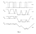
- FIG. 4 a series of four graphs are shown that illustrate the effects of the velocity between image sensor 320 and barcode 120 when capturing an image of a linear barcode.
- Each graph illustrates reading the start/stop pattern of a standard C39 barcode at a different velocity, v, with respect to image sensor 320.
- the vertical axes represents increasing level of brightness/lightness ( i.e. upper level representing white and lower levels representing black).
- the C39 barcode standard uses a fixed ratio between the widest and thinnest black and white bars that barcode decoding system 300 interprets to decode the codeword.
- the C39 start/stop pattern illustrated in FIG. 4 is made up of the following sequence of bars: narrow black; wide white; narrow black; narrow white; wide black; narrow white; wide black; narrow white; and narrow black.
- image sensor 320 of barcode scanner 102 affects the accuracy of interpreting the codeword and the entire barcode 102.
- Motion between image sensor 320 and barcode 120 can result in motion blur in the captured image that causes errors when decoding barcode 120.
- the motion blur is proportional to the velocity of the motion.
- Other barcode standards can encode information using other known methods and are similarly prone to errors from motion as described below.
- the velocity in each graph is related to the slope of each edge of the black and white bars of barcode 120 such that a larger velocity or slope represents a blurrier edge between white and black bars in the image.
- an edge detection algorithm can still perform relatively well as the signal to noise ratio is still relatively good since a moving target can help average and cancel noise from sources such as dirt in the optical path, light distortion, print quality, cross-talk, bad pixels, etc. Motion causes these noise sources to be distributed and averaged over multiple pixels of image sensor 320.
- An edge detection algorithm can be adjusted for a lower or higher velocity as will be described below.
- An edge detection algorithm adjusted for a lower velocity may fail at a higher velocity due to a lower signal amplitude while an edge detection algorithm adjusted to work at a higher velocity may fail at a lower velocity since it is more susceptible noise. Failure to properly adjust the edge detection algorithm for the appropriate velocity will result in failure to detect edges of the black and white bars and failure to decode barcode 120.
- a different or variation of the edge detection algorithm can be selected based on velocity.
- Graphs 400, 401, 402, and 403 illustrate how the upper and lower detection limits of an edge detection algorithm, shown as horizontal lines, can be adjusted to accurately detect the edges of features of barcode 120. Selecting a higher detection threshold, such as that shown in graph 400 where the upper detection limit for detecting a black to white transition is near the maximum signal level and the lower detection limit for detecting a white to black transition is near the minimum signal level, helps to filter noise from the captured image and performs well in high contrast and/or low velocity conditions.
- Graphs 401, 402, and 403 illustrate selecting a lower detection threshold where the upper detection limit and lower detection limit are adjusted to accurately capture the width of the bars from the signal. The upper detection limit captures a white bar and the lower detection limit captures a black bar.
- the lower detection threshold has less distance between the upper and lower detection limits that may make the detection algorithm more susceptible to noise, a lower detection threshold can be used for higher relative velocity conditions where noise in the optical path is averaged over multiple pixels of image sensor 320.
- Edge detection processing based on thresholds is provided as an example of how knowledge of the velocity between barcode 120 and image sensor 320 can be used to adjust the edge detection processing.
- Other edge detection algorithms that use a different edge detection mechanism can also be adjust based on the velocity information.
- Some edge detection algorithms use a derivative of the scan to determine the edges of the features of barcode 120 (i.e. where the second derivate is zero indicates a change in contrast between the features of barcode 120). Since higher velocities can effectively cancel spurious noise, these derivative-based edge detection algorithms can also use the velocity between image sensor 320 and barcode 120 to adjust the edge detection processing such that the algorithm can be adjusted to be more sensitive to changes in the derivatives to determine the edges of the features of barcode 120. Accordingly, other edge detection algorithms can be adjusted based on the velocity between the image sensor 320 and barcode 102 to either compensate for the cancelled spurious noise in the captured image or the less prominent edges of features of barcode 120 in the captured image.
- Image sensor 320 and motion sensor 318 can be implemented as separately packaged parts, provided only that, motion sensor 318 must move with image sensor 320.
- Remaining elements such as barcode orientation extractor 502 velocity vector calculator 504, and edge detection decoder 506, can be implemented either together or separately, and, at least in part, as software code executed on processor 302 or implemented in custom logic, such as an ASIC or programmable logic device, including but not limited to FPGAs or DSPs.
- processor as used herein can refer to a microprocessor, such as processor 302, or a custom logic solution, such as an ASIC or FPGA.
- Image sensor 320 captures an image of barcode 120. Typically, the capture operation is initiated through a user's interaction with handheld computing device 100 or barcode scanner 102. The captured image typically includes barcode 120 and the surrounding background.
- Barcode orientation extractor 502 determines the orientation of barcode 120 in the captured image.
- Barcode orientation extractor 502 processes the captured image to determine the orientation of barcode 120 within the captured image based on, for example, the skew of barcode 120 or the angle of features of barcode 120.
- the determined orientation of the captured image of barcode 120 is provided to velocity vector calculator 504.
- Velocity vector calculator 504 uses acceleration data provided from motion sensor 318 to determine velocity, as will be described below. Velocity vector calculator 504 uses the determined orientation and the determined velocity, to determine the velocity of barcode scanner 102 in a direction perpendicular to barcode features ( i.e. the long side of bar in a 1D barcode or the side of a cell in a 2D barcode).
- Barcode orientation extractor 502 can determine the orientation of bars of a 1D barcode or the squares or rectangles of a 2D barcode using any suitable image processing algorithm as will occur to those skilled in the art.
- image processing can convert the captured image to binary using dynamic thresholding and then use chain-code processing to effectively outline the features of barcode 120 in the captured image.
- the result of chain-code processing for each feature of barcode 120 will be the smallest wrapping rectangle.
- the orientation of these rectangles can then provide the best statistical orientation of the features of barcode 120.
- barcode orientation extractor 502 can use image processing based on the correlation of multiple scan directions.
- the image processing algorithm can detect the location of barcode 120 within the captured image.
- several short scans are performed at different angles through the detected location to detect the edges of the features of barcode 120. Scans at angles that have the highest mutual correlation correspond to the angle that is perpendicular to the features of barcode 120 to determine orientation.
- barcode orientation extractor 502 can also be provided with position data from motion sensor 318 to determine the position of barcode scanner 102 in free space (relative to a reference position) to assist with determining the orientation of barcode 120 based on a presumed or statistical orientation of barcode 102. For example, if the majority of barcodes are parallel with the horizon, this information can assist the orientation extraction process. Barcode orientation extractor 502 can also provide a preprocessed image to edge detection decoder 506 such that the image has been de-skewed and/or background information removed.
- Velocity vector calculator 504 determines the velocity of image sensor 320 that is associated with motion sensor 318.
- the velocity is preferably calculated for the exposure period of image sensor 320 when capturing the image of barcode 120.
- the exposure period includes the time that image sensor 320 is collecting light to capture the image.
- the term "exposure period" can also include the time immediately prior to or after capturing the image such that the velocity can be calculated using either prior or post measurements, an average or any other combination thereof.
- Determining the velocity of image sensor 320 uses data from motion sensor 318 and then determines the velocity with respect to a direction perpendicular to the edges of features of barcode 120.
- Velocity can be calculated by applying digital integration to the translational acceleration data from motion sensor 318.
- Velocity vector calculator can also use the distance between the image sensor 320 and barcode 120 in calculating velocity if motion sensor 318 includes a gyroscope that provides angular acceleration (i.e. pitch, yaw or roll in degrees per second). The distance can be derived from the variable or managed focus information from image sensor 320.
- velocity vector calculator 504 determines the velocity of image sensor 320 in a direction perpendicular to the edges of the bars that comprise barcode 120 in the captured image. With a 2D barcode, velocity vector calculator can determine a velocity in directions perpendicular to the edges of the 2D barcode features. Most current 2D barcode have orthogonal features (i.e . squares or rectangles) but other variations can use triangles, hexagons or other geometric shapes that can require determining the velocity in more than two directions.
- Velocity vector calculator 504 uses acceleration data provided by motion sensor 318 to adjust a previously calculated velocity of image sensor 320. Velocity can be continuously updated by acceleration data from motion sensor 318. Velocity vector calculator 504 can use a motion model, such as a periodic (or quasi-periodic) motion model that simulates motion of the human hand, to assist with determining the velocity from the acceleration data. Generally, velocity information cannot be obtained strictly from acceleration data without knowledge of an initial velocity. Using a motion model allows velocity vector calculator 504 to recover velocity from acceleration data. For example, in a simplified pendulum motion model when acceleration changes from one direction to an opposite direction, the simplified pendulum motion model provides that the object had a velocity of zero some time between the change in direction of acceleration.
- a motion model can be selected based on acceleration data or position information from motion sensor 318 so that velocity can be determined accurately based on acceleration data.
- position data based on acceleration data from motion sensor 318 can also be used to select an appropriate motion model based on the orientation of how barcode scanner 102 is being held by an operator.
- Periodic motion models are based on the fact that most motion activities in the human body are happening at 8 Hertz and below. Periodic motion appears in hand jitter patterns that are a common source of image blur with a handheld image sensor 320.
- image sensor 320 captures an image in 10-20 ms in average light condition (e.g. an office environment with a brightness of approximately 300 lux) this provides a capture time that is less that 1/8 of the period of human body motion.
- velocity vector calculator 504 can interpolate a constant velocity (assuming no acceleration between image parts) during the period that the image was captured by image sensor 320.
- a motion model can include a pendulum-like motion where acceleration and velocity are shifted relative to each other by a quarter period and their amplitudes are proportional to each other.
- Other embodiments can include other motion models or more complicated motion models that better fit the acceleration data received by velocity vector calculator 504.
- velocity vector calculator 504 can select a motion model or frequency based on received acceleration data from motion sensor 318. Preferably, at least two periods of periodic motion are used to select a frequency.
- the received acceleration data can include acceleration data for past image captures and can be associated with a user profile so that a motion model may be refined for a particular user.
- Edge detection decoder 506 processes the captured image using an edge detection algorithm to determine the edges of the features of barcode 120 in order to decode barcode 120.
- Edge detection decoder 506 determines at least one parameter for edge detection processing of the barcode 120 based on the velocity (including direction(s)) received from velocity vector calculator 504.
- Edge detection decoder 506 can make this determination based on the velocity perpendicular to the features of barcode 120 provided by velocity vector calculator 504.
- Edge detection decoder 506 determines the amount of motion-induced image blur using the determined velocity received from velocity vector calculator 504 and any one or combination of the following factors including, but not limited to: size of features of barcode 120; the resolution of image sensor 320; and the focal distance of the lens.
- the amount of velocity induced blur is used to select parameters to adjust and/or select the edge detection algorithm.
- edge detection decoder 506 can use the resolution of image sensor 320 and the determined velocity to determine that 2.5 pixels are affected by gradient shading due to the determined velocity provided by velocity vector calculator 504. If the minimum size of features of barcode 120 is 10 pixels, then no adjustment, or a very minimal adjustment, would be required to adjust for the motion-induced image blur. However, if the minimum size of features of barcode 120 is 3 pixels then edge detection decoder 506 may select parameters to adjust the upper and lower detection limits of the edge detection algorithm. The appropriate parameter(s) is/are selected to adjust the edge detection algorithm (or to select the appropriate edge detection algorithm) to accurately detect the edges of features of barcode 120 to compensate for the motion-induced image blur from the determined velocity.
- Edge detection algorithms typically operate to detect a change in contrast at a point in the image (e.g. between a black and white bar in barcode 120) and then compares that change in contrast to a detection limit to determine whether an edge exists.
- Edge detection decoder 506 can adjust these detection limits based on the velocity of barcode scanner 102.
- the detection thresholds as illustrated in FIG. 4 are provided as one example of a parameter for edge detection processing.
- Other parameters used to adjust edge detection processing can include edge position, edge shape or edge pattern.
- the edge shape can be affected by noise from image sensor 320 or noise inherent in barcode 120 that may be due to dirt in the optical path, light distortion, print quality, etc. that the algorithm needs to separate from the motion-induced image blur.
- Edge pattern information can be used to tune the algorithm based on a start/stop pattern or a fixed ratio between the bars and spaces.
- Another parameter could be used to select an appropriate edge detection algorithm such as, for example, using a differential edge detection algorithm.
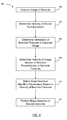
- a flowchart 600 is shown illustrating an example method for compensating for motion between image sensor 320 of barcode scanner 102 and barcode 120 to improve barcode decoding.
- an image of barcode 120 is captured using image sensor 320 of barcode scanner 102. Capturing the image is typically initiated by a user of handheld computing device 100 through a user interface interaction, such as pressing a key of keyboard 104 or specifically tasked button or trigger of barcode scanner 102.
- the velocity of barcode scanner 102 is determined during the period of time the image was captured by image sensor 320.
- image sensor 320 can take from 10 to 60 milliseconds to capture the image.
- the velocity is determined from the acceleration data provided by motion sensor 318. Acceleration data is used along with a motion model in order to determine the velocity.
- the velocity of image sensor 320 is continually adjusted between (or just prior to) capture events based on the acceleration data and the motion model.
- the orientation of features of barcode 120 in the captured image is determined.
- the captured image can be processed to determine the orientation by detecting the skew or angle of barcode 120 and its features.
- Orientation information is used to determine the orientation of features of the barcode in the captured image with respect to the axes of measurement of motion sensor 318 in order to determine velocity in a direction along barcode 120.
- This is calculated in step 608 where the orientation and velocity are used to determine the velocity of image sensor 320 in a direction substantially perpendicular to edges of the features of barcode 120.
- a plurality of velocities can be determined such that each velocity is substantially perpendicular to one of a plurality of edge of features of the barcode.
- orthogonal 2D barcodes this involves calculating two velocities that are perpendicular to each other but other 2D barcodes can use non-orthogonal shapes (e.g. triangles) as barcode features that can require determining three different velocities. This can involve mapping a velocity vector calculated in step 604 to the direction of the edges of the features of barcode 120.
- step 610 at least one parameter is selected for edge detection processing of barcode 120 based on the determined velocity to compensate for blurring of the captured image due motion between image sensor 320 of barcode scanner 102 and barcode 120.
- the parameter can include a sensitivity threshold that is selected based on the determined velocity so that a lower sensitivity is selected for higher velocities.
- Other parameters of edge detection processing that can be adjusted based on velocity can include any one of edge position, edge shape, or an edge pattern.
- the edge detection processing commences using the provided parameters to process the captured image of barcode 120 to detect the edges of the features of barcode 120 in order to identify barcode symbols for decoding.
Abstract
Description
- The present invention relates generally to a system and method for decoding or reading barcodes, more specifically to barcode decoding reading devices using image sensors.
- Barcode symbols provide a fast and accurate means of representing information about an object. Decoding or reading a barcode is accomplished by translating the pattern of barcode features, such as bars and spaces in linear (1 D) barcodes or blocks or other features in a two-dimensional (2D) barcode, into the corresponding numbers or characters. Barcodes are widely used for encoding information and tracking purposes in retail, shipping and industrial settings.
- Barcodes are typically read by a handheld barcode reading device that includes a camera or imager (these terms being used interchangeably herein) for capturing an image of the barcode. Since the reading device is handheld, the quality of the captured image can suffer due to hand movement of the reading device relative to the barcode during the image capture period. For example, movement in the direction perpendicular to the bars and spaces with a linear barcode can result in a blurring that causes misdetection of the edges between the bars and spaces in decoding the barcode. For 2D barcodes, motion in any direction can induce image blur that results in misdetection of the barcode feature. The image blurring problem can be exasperated when using low cost image sensors that require longer exposure periods to capture images with suitable signal to noise ratios or when attempting to capture an image of a barcode under less than ideal lighting condition which also requires a relatively longer exposure period.
- Optical stabilization techniques are often used to reduce blurring associated with the motion of a camera during exposure to compensate for movement of the imaging device. Optical stabilization varies the optical path to the image sensor of the camera in response to movement. This technology can be implemented in the lens itself, or by moving the sensor as the final element in the optical path. The key element of all optical stabilization systems is that they stabilize the image projected on the sensor before the sensor converts the image into digital information. Optical stabilization techniques typically require additional sensors, such as gyroscopes and accelerometers, and devices to move lenses or sensors in the optical path. These additional sensors and devices create a number of potential disadvantages in a handheld device, such as increasing the expense of the handheld device, increasing the number of moving parts in the handheld device, possibly reducing the overall reliability, and increasing the power consumption within the handheld device.
- Another known technique used to minimize motion blur relies on using an accelerometer to detect pauses in hand motion. This technique only allows the camera to attempt to capture an image during a detected pause in motion. This technique requires knowledge of the expected motion pattern of hand jitter in order to correctly detect the pauses. This technique is used by some cell phone cameras, one example being the Glogger VS2 software available for Nokia phones running on Symbian OS. Our published
U.S. Patent Application 20050236488 (Kricorissian ), discusses another implementation of a delay-based system. These approaches have proven not to be practicable for barcode readers because they often create an unacceptable delay when capturing the image of the barcode. Furthermore, these approaches may still result in blurring of the captured image in lower light environments or when using a low-cost image sensor where a longer exposure time is required since these approaches do not prevent blurring or compensate for blur causing movement, but instead merely attempt to avoid capturing the image of the barcode when movement is occurring. - An alternative approach to reduce image blurring is to reduce exposure times. However, imagers used in barcode reading devices are typically lower cost image sensors that require relatively longer exposure times. In the scanning environments where barcode reading devices are typically used, the light levels are often not sufficient to use reduced exposure times to eliminate image blurring. Providing supplementary lighting, such as a flash or other light source, can reduce the exposure time, but would result in increased power consumption by the handheld device with a commensurate reduction in the useful operating time of the battery powered handheld device.
- Accordingly, there is a need for a system and method for compensating for motion between an image sensor and barcode when capturing an image of the barcode.
- According to a first aspect, there is provided a method for compensating for motion between an image sensor and a barcode, the method comprising the steps of capturing an image of the barcode using the image sensor; determining a velocity between the image sensor and the barcode based on acceleration data provided by a motion sensor, the velocity determined for an exposure period of the image sensor to capture the image; selecting at least one parameter for edge detection processing of the barcode based on the determined velocity to compensate for blurring of the image due to the determined velocity; and detecting edges of features of the barcode in the captured image using the at least one parameter to decode the barcode. Preferably, the motion sensor and image sensor are included in a handheld barcode scanner. Also preferably, the step of determining the velocity comprises calculating a previous velocity of the image sensor, and adjusting the previous velocity with the acceleration data to determine the velocity. Also preferably, the determined velocity is calculated using a motion model, such as a periodic or quasi-periodic motion model. Also preferably, the method further includes the step of determining the velocity in a direction substantially perpendicular to edges of features of barcode. Other preferred features are set out in the subsidiary claims.
- According to a second aspect of the present invention, there is provided a barcode decoding system for capturing and decoding a barcode, the system comprising: an image sensor for capturing an image of the barcode; a motion sensor for collecting acceleration data for motion between the image sensor and the barcode; and a processor configured to determine a velocity of the motion between the image sensor and the barcode based on the acceleration data, the velocity determined for an exposure period of the image sensor to capture of the image, the processor further configured to select at least one parameter for edge detection processing of the barcode based on the determined velocity to compensate for blurring of the image due to the determined velocity, and the processor further configured to detect edges of features of the barcode using the at least one parameter to decode the barcode.
- Embodiments of the present invention will now be described, by way of example only, with reference to the attached drawings, wherein:
-
FIG. 1 is a perspective view of a handheld computing device; -
FIG. 2 is a rear view of the handheld computing device ofFIG. 1 illustrating motion of the handheld computing device relative to a barcode; -
FIG. 3 is a block diagram of a barcode decoding system illustrating the interconnection of the functional subsystems; -
FIG. 4 is a series of four graphs illustrating the effects of the velocity between an image sensor of a barcode scanner and a barcode when capturing an image of a linear barcode; -
FIG. 5 is a block diagram of relevant elements of a barcode decoding system that provide motion compensation and barcode decoding functionality; and -
FIG. 6 is a flowchart illustrating a method for compensating for motion between an image sensor of a barcode scanner relative and a barcode to improve barcode decoding. - It will be appreciated that for simplicity and clarity of illustration, where considered appropriate, numerous specific details are set forth in order to provide a thorough understanding of the embodiments described herein. However, it will be understood by those of ordinary skill in the art that the embodiments described herein may be practiced without these specific details. In other instances, well-known methods, procedures and components have not been described in detail so as not to obscure the embodiments described herein. Furthermore, this description is not to be considered as limiting the scope of the embodiments described herein in any way, but rather as merely describing the implementations of various embodiments described herein.
- The embodiments of the systems, devices and methods described herein may be implemented in hardware or software, or a combination of both. Some of the embodiments described herein may be implemented in computer programs executing on programmable computers, each computer comprising at least one processor, a computer memory (including volatile and non-volatile memory), at least one input device, and at least one output device. For example, and without limitation, the programmable computers can include handheld computing devices, or the combination of a portable or fixed computing device with a handheld barcode scanner where either the computing device or the handheld barcode scanner can be programmable. Program code may operate on input data to perform the functions described herein and generate output data.
- Reference is first made to
FIGS. 1 and2 which show ahandheld computing device 100 having abarcode scanner 102 that provides optical barcode scanning functionality.Handheld computing device 100 can be any of a wide range of digital devices that provides barcode reading functionality including, without limitation, devices which generate digital information, such as computer terminals, RFID readers and optical scanning devices, including dedicated barcode scanning devices, digital photo and document scanners.Handheld computing device 100 is a handheld portable device, such as a mobile computer, mobile phone, handheld terminal, digital camera, scanner or other electronic device configured to capture and decode barcode images. Barcodescanner 102, as described in further detail below, may comprise a set of hardware, firmware, and system software, employed in any suitable combination in order to capture an image ofbarcode 120 using an image sensor. -
Handheld computing device 100 can further include akeyboard 104 for user input, adisplay screen 106, and anexpansion port 108. Examples ofexpansion port 108 can include a Universal Serial Bus (USB) port or other similar expansion port for coupling compatible peripheral devices such as, but not limited to, a communication and synchronization cradle forhandheld computing device 100. - As used herein, the term barcode refers to an optical machine-readable representation of information. Typically, barcodes encode information in the widths and the spacing of parallel lines, sometimes referred to as bars, and may be referred to as linear or 1D (one-dimensional) barcodes or symbologies. Barcode 120 is provided as an example of a linear barcode. Barcodes can also encode information in patterns of squares, dots, hexagons and other geometric shapes or symbols within images termed 2D (two-dimensional) matrix codes or symbologies. Although 2D barcodes use features other than bars, they are generally referred to as barcodes as well. Accordingly, the barcode images discussed herein for use with
barcode scanner 102 can refer to either 1D or 2D barcodes. As will be described, the barcodes can be read by an optical scanner or reader referred to collectively asbarcode scanner 102. As used herein, the objects used to encode the information, such as bars, squares, etc., are referred to as features. For example, the features ofbarcode 120 can refer to the either the black or white bars that comprisebarcode 120. Barcodes can also be black-and-white or colour. -
Arrow 122 is used to represent motion ofbarcode scanner 102 andhandheld computing device 100 relative tobarcode 120. It is difficult for a user to maintainhandheld computing device 100 steady while capturingbarcode 120 and this movement can induce motion blur in the captured image that could affect the ability ofhandheld computing device 100 to decodebarcode 120. - Referring now to
FIG. 3 , a block diagram of abarcode decoding system 300 is shown illustrating the interconnection of the functional subsystems.Handheld computing device 100 can includebarcode decoding system 300 to provide barcode decoding and other functions.Barcode decoding system 300 comprises aprocessor 302 that controls general operation of the system.Processor 302 interacts with functional device subsystems, which can include subsystems such asdisplay screen 106,flash memory 304, random access memory (RAM) 306, auxiliary input/output (I/O)subsystems 308,serial port 310,keyboard 104,speaker 312, short-range communications subsystem 314, such as Bluetooth™ for example, andexpansion port 108.Barcode decoding system 300 can include a power source such as battery module (not shown) that can be removable and replaceable. While the illustrated embodiment ofbarcode decoding system 300 includes the functional subsystems described above, it will be apparent to those of skill in the art thatbarcode decoding system 300 can omit some of these subsystems and/or can include additional subsystems as required to meet an intended field of use forbarcode decoding system 300. -
Barcode decoding system 300 can have the capability of communicating at least data, and possibly any of data, audio and voice communications, to and from other devices connected by a communication network, as well as data acquisition sources within a communication network.Barcode decoding system 300 can include wired or wireless communication capability. In the wireless configuration,barcode decoding system 300 typically includes radio frequency (RF)communication subsystem 316, which includes a receiver, a transmitter, and associated components, such as one or more embedded or internal antennae, and a processing module such as a digital signal processor (DSP) or the like. As will be apparent to those skilled in field of communications, the particular design ofRF communication subsystem 316 depends on the specific communication networks in whichbarcode decoding system 300 is intended to operate, and can include communication functionalities such as radio-frequency identification (RFID), Wi-Fi WLAN based on IEEE 802.11 standards, Zigbee, Z-Wave, GSM EDGE, 1 EVDO, HSPDA, and the like. - Still with regard to
FIG. 3 , operating system software can be executed byprocessor 302 that is stored in a persistent storage such asflash memory 304, or alternatively, in other read-only memory (ROM) or similar storage elements (not shown). Those skilled in the art will appreciate that an operating system, specific device applications, or parts thereof, may be temporarily loaded into a volatile store such as RAM 306. -
Processor 302, in addition to its operating system functions, can also enable execution of software applications onbarcode decoding system 300. A predetermined set of applications, which control basic device operations, or more customized, advanced device operations, may be installed onbarcode decoding system 300 during its manufacture, such as during the components configuration process. -
Display screen 106 ofbarcode decoding system 300 may be used to visually present a software application's graphical user interface (GUI) to a user viadisplay screen 106.Display screen 106 can employ a touch screen display, in which case the user can manipulate application data by modifying information on the GUI using direct touches by a finger or stylus. Depending on the type ofhandheld computing device 100, the user may have access to other types of input devices, such as, for example, a scroll wheel, trackball or light pen. - A graphical user interface presented on
display screen 106 ofbarcode decoding system 300 may enable an operator or administrator to interact withhandheld computing device 100. It is further contemplated thatbarcode decoding system 300 may be communicatively coupled to a remotely located database (not shown). -
Barcode decoding system 300 further comprisesbarcode scanner 102.Barcode scanner 102 can be integrated withhandheld computing device 100 as shown inFIGS. 1 and2 . In other embodiments,barcode scanner 102 can comprise a secondary handheld enclosure that can includemotion sensor 318 and some of other the subsystems illustrated inFIG. 3 . For example,barcode scanner 102 can be a pistol scanner that is communicatively tethered tobarcode decoding system 300. The pistol scanner can includemotion sensor 318 andimage sensor 320, and the pistol scanner can further include a trigger and logic to control the operation of the pistol scanner. The pistol scanner can be tethered tobarcode decoding system 300 either by wire, such as a USB link, or through a wireless protocol that communicates with short-range communication subsystem 314 ofhandheld computing device 100. The term "handheld barcode scanner" as used herein can refer to eitherbarcode scanner 102 integrated withinhandheld computing device 100 or a secondary handheld enclosure withbarcode scanner 102 that can connect to the subsystems ofbarcode decoding system 300. -
Barcode scanner 102 can comprise any suitable combination of software, firmware and hardware to implement scanning ofbarcode 120 usingimage sensor 320.Image sensor 320 can further include a light source and a lens (not shown). The light source and lens can be controlled byimage sensor 320 orprocessor 302. The lens can be a fixed focus lens with a suitable depth of field, or can be an auto-focus lens.Image sensor 320 can be a CCD, CMOS or other suitable image sensor. - If
barcode scanner 102 is implemented in a secondary handheld enclosure,barcode scanner 102 can further include amotion sensor 318 that can provide acceleration data with respect to the motion ofbarcode scanner 102. Acceleration data is used bybarcode scanner 102 to recover the velocity ofbarcode scanner 102. Ifbarcode scanner 102 is integrated withhandheld computing device 100,motion sensor 318 can be a separate subsystem connecting tobarcode decoding system 300 in order to provide acceleration data with respect to the motion ofbarcode scanner 102. In some embodiments,motion sensor 318 can be an accelerometer that provides linear/translational acceleration data in one or more planes of movement according to the axes of the accelerometer (e.g. x, y, and z). In other embodiments,motion sensor 318 can be a gyroscope that has axes to measures pitch, yaw and roll and provides acceleration data in the form of degrees per second. Using the distance frombarcode 120, which can be estimated based on focal length or other factors, angular acceleration data from the gyroscope can be used to approximate translational acceleration data similar to that obtained from an accelerometer. A gyroscope can also provide positional orientation information relative to a reference position. Acceleration data may be provided from both an accelerometer and a gyroscope to provide more accurate acceleration data.Motion sensor 318 can be implemented as a MEMS sensor and can include either an accelerometer, a gyroscope, or a combination thereof in a single part. Velocity can be determined from the acceleration data provided bymotion sensor 318 as will be described further below. - Acceleration data can further include timestamp data that may be used to determine velocity. Depending on where acceleration data is processed,
motion sensor 318 can provide acceleration data toprocessor 302 or directly tobarcode scanner 102. - In most cases it is assumed that
barcode 120 is static (or moving an insignificant amount) and the motion ofbarcode scanner 102 andimage sensor 320 with respect tobarcode 120 causes image blur in the capture image. However, in some embodiments,barcode 120 may be moving with respect to astatic barcode scanner 102. In that case,motion sensor 318 can be used to provide movement information ofbarcode 120 to capture motion ofbarcode 120 as opposed to motion ofbarcode scanner 102 andimage sensor 320. For example, ifimage sensor 320 is statically mounted to capture images ofbarcode 120 placed on a moving object, such as a conveyor or platform,motion sensor 318 can capture this movement and provide it tobarcode decoding system 300. For example,motion sensor 318 can provide acceleration data of a conveyor or platform thatbarcode decoding system 300 can use to determine the velocity betweenimage sensor 320 and barcode 120 (i.e. the velocity of the conveyor or platform in this case). - Referring now to
FIG. 4 , a series of four graphs are shown that illustrate the effects of the velocity betweenimage sensor 320 andbarcode 120 when capturing an image of a linear barcode. Each graph illustrates reading the start/stop pattern of a standard C39 barcode at a different velocity, v, with respect toimage sensor 320. The vertical axes represents increasing level of brightness/lightness (i.e. upper level representing white and lower levels representing black). - The C39 barcode standard uses a fixed ratio between the widest and thinnest black and white bars that
barcode decoding system 300 interprets to decode the codeword. The C39 start/stop pattern illustrated inFIG. 4 is made up of the following sequence of bars: narrow black; wide white; narrow black; narrow white; wide black; narrow white; wide black; narrow white; and narrow black. Conventionally, how accurate this array of widths is recreated byimage sensor 320 ofbarcode scanner 102 affects the accuracy of interpreting the codeword and theentire barcode 102. Motion betweenimage sensor 320 andbarcode 120 can result in motion blur in the captured image that causes errors when decodingbarcode 120. The motion blur is proportional to the velocity of the motion. Other barcode standards can encode information using other known methods and are similarly prone to errors from motion as described below. -
First graph 400 illustrates the case where the velocity ofbarcode 120 with respect toimage sensor 320 is zero, i.e. v=0. Detection of black and white bars ofbarcode 120 can be performed fairly accurately using an edge detection algorithm if the image ofbarcode 120 has a high signal to noise ratio so that there is sufficient contrast. The vertical lines in the signal indicate a strong contrast between the black and white bars. -
Graphs barcode 120 andimage sensor 320. The velocity in each graph is related to the slope of each edge of the black and white bars ofbarcode 120 such that a larger velocity or slope represents a blurrier edge between white and black bars in the image. With a fairly low speed, an edge detection algorithm can still perform relatively well as the signal to noise ratio is still relatively good since a moving target can help average and cancel noise from sources such as dirt in the optical path, light distortion, print quality, cross-talk, bad pixels, etc. Motion causes these noise sources to be distributed and averaged over multiple pixels ofimage sensor 320. An edge detection algorithm can be adjusted for a lower or higher velocity as will be described below. An edge detection algorithm adjusted for a lower velocity may fail at a higher velocity due to a lower signal amplitude while an edge detection algorithm adjusted to work at a higher velocity may fail at a lower velocity since it is more susceptible noise. Failure to properly adjust the edge detection algorithm for the appropriate velocity will result in failure to detect edges of the black and white bars and failure to decodebarcode 120. Alternatively, a different or variation of the edge detection algorithm can be selected based on velocity. -
Graphs barcode 120. Selecting a higher detection threshold, such as that shown ingraph 400 where the upper detection limit for detecting a black to white transition is near the maximum signal level and the lower detection limit for detecting a white to black transition is near the minimum signal level, helps to filter noise from the captured image and performs well in high contrast and/or low velocity conditions.Graphs image sensor 320. - Edge detection processing based on thresholds is provided as an example of how knowledge of the velocity between
barcode 120 andimage sensor 320 can be used to adjust the edge detection processing. Other edge detection algorithms that use a different edge detection mechanism can also be adjust based on the velocity information. Some edge detection algorithms use a derivative of the scan to determine the edges of the features of barcode 120 (i.e. where the second derivate is zero indicates a change in contrast between the features of barcode 120). Since higher velocities can effectively cancel spurious noise, these derivative-based edge detection algorithms can also use the velocity betweenimage sensor 320 andbarcode 120 to adjust the edge detection processing such that the algorithm can be adjusted to be more sensitive to changes in the derivatives to determine the edges of the features ofbarcode 120. Accordingly, other edge detection algorithms can be adjusted based on the velocity between theimage sensor 320 andbarcode 102 to either compensate for the cancelled spurious noise in the captured image or the less prominent edges of features ofbarcode 120 in the captured image. - Referring now to
FIG. 5 , a block diagram 500 of relevant elements ofbarcode decoding system 300 that provide motion compensation and barcode decoding functionality is shown.Image sensor 320 andmotion sensor 318 can be implemented as separately packaged parts, provided only that,motion sensor 318 must move withimage sensor 320. Remaining elements, such asbarcode orientation extractor 502velocity vector calculator 504, andedge detection decoder 506, can be implemented either together or separately, and, at least in part, as software code executed onprocessor 302 or implemented in custom logic, such as an ASIC or programmable logic device, including but not limited to FPGAs or DSPs. The term "processor" as used herein can refer to a microprocessor, such asprocessor 302, or a custom logic solution, such as an ASIC or FPGA. -
Image sensor 320 captures an image ofbarcode 120. Typically, the capture operation is initiated through a user's interaction withhandheld computing device 100 orbarcode scanner 102. The captured image typically includesbarcode 120 and the surrounding background. - The captured image from
image sensor 320 is then provided tobarcode orientation extractor 502 that determines the orientation ofbarcode 120 in the captured image.Barcode orientation extractor 502 processes the captured image to determine the orientation ofbarcode 120 within the captured image based on, for example, the skew ofbarcode 120 or the angle of features ofbarcode 120. The determined orientation of the captured image ofbarcode 120 is provided tovelocity vector calculator 504. -
Velocity vector calculator 504 uses acceleration data provided frommotion sensor 318 to determine velocity, as will be described below.Velocity vector calculator 504 uses the determined orientation and the determined velocity, to determine the velocity ofbarcode scanner 102 in a direction perpendicular to barcode features (i.e. the long side of bar in a 1D barcode or the side of a cell in a 2D barcode). -
Barcode orientation extractor 502 can determine the orientation of bars of a 1D barcode or the squares or rectangles of a 2D barcode using any suitable image processing algorithm as will occur to those skilled in the art. In one embodiment, image processing can convert the captured image to binary using dynamic thresholding and then use chain-code processing to effectively outline the features ofbarcode 120 in the captured image. The result of chain-code processing for each feature ofbarcode 120 will be the smallest wrapping rectangle. The orientation of these rectangles can then provide the best statistical orientation of the features ofbarcode 120. - Alternatively,
barcode orientation extractor 502 can use image processing based on the correlation of multiple scan directions. First, the image processing algorithm can detect the location ofbarcode 120 within the captured image. Next, several short scans are performed at different angles through the detected location to detect the edges of the features ofbarcode 120. Scans at angles that have the highest mutual correlation correspond to the angle that is perpendicular to the features ofbarcode 120 to determine orientation. - In other embodiments,
barcode orientation extractor 502 can also be provided with position data frommotion sensor 318 to determine the position ofbarcode scanner 102 in free space (relative to a reference position) to assist with determining the orientation ofbarcode 120 based on a presumed or statistical orientation ofbarcode 102. For example, if the majority of barcodes are parallel with the horizon, this information can assist the orientation extraction process.Barcode orientation extractor 502 can also provide a preprocessed image to edgedetection decoder 506 such that the image has been de-skewed and/or background information removed. -
Velocity vector calculator 504 determines the velocity ofimage sensor 320 that is associated withmotion sensor 318. The velocity is preferably calculated for the exposure period ofimage sensor 320 when capturing the image ofbarcode 120. The exposure period includes the time thatimage sensor 320 is collecting light to capture the image. As used herein, the term "exposure period" can also include the time immediately prior to or after capturing the image such that the velocity can be calculated using either prior or post measurements, an average or any other combination thereof. - Determining the velocity of
image sensor 320 uses data frommotion sensor 318 and then determines the velocity with respect to a direction perpendicular to the edges of features ofbarcode 120. Velocity can be calculated by applying digital integration to the translational acceleration data frommotion sensor 318. Velocity vector calculator can also use the distance between theimage sensor 320 andbarcode 120 in calculating velocity ifmotion sensor 318 includes a gyroscope that provides angular acceleration (i.e. pitch, yaw or roll in degrees per second). The distance can be derived from the variable or managed focus information fromimage sensor 320. - If
barcode 120 is a linear barcode,velocity vector calculator 504 determines the velocity ofimage sensor 320 in a direction perpendicular to the edges of the bars that comprisebarcode 120 in the captured image. With a 2D barcode, velocity vector calculator can determine a velocity in directions perpendicular to the edges of the 2D barcode features. Most current 2D barcode have orthogonal features (i.e. squares or rectangles) but other variations can use triangles, hexagons or other geometric shapes that can require determining the velocity in more than two directions. -
Velocity vector calculator 504 uses acceleration data provided bymotion sensor 318 to adjust a previously calculated velocity ofimage sensor 320. Velocity can be continuously updated by acceleration data frommotion sensor 318.Velocity vector calculator 504 can use a motion model, such as a periodic (or quasi-periodic) motion model that simulates motion of the human hand, to assist with determining the velocity from the acceleration data. Generally, velocity information cannot be obtained strictly from acceleration data without knowledge of an initial velocity. Using a motion model allowsvelocity vector calculator 504 to recover velocity from acceleration data. For example, in a simplified pendulum motion model when acceleration changes from one direction to an opposite direction, the simplified pendulum motion model provides that the object had a velocity of zero some time between the change in direction of acceleration. A motion model can be selected based on acceleration data or position information frommotion sensor 318 so that velocity can be determined accurately based on acceleration data. For example, position data based on acceleration data frommotion sensor 318 can also be used to select an appropriate motion model based on the orientation of howbarcode scanner 102 is being held by an operator. - Periodic motion models are based on the fact that most motion activities in the human body are happening at 8 Hertz and below. Periodic motion appears in hand jitter patterns that are a common source of image blur with a
handheld image sensor 320. Typically,image sensor 320 captures an image in 10-20 ms in average light condition (e.g. an office environment with a brightness of approximately 300 lux) this provides a capture time that is less that 1/8 of the period of human body motion. Using a periodic motion model,velocity vector calculator 504 can interpolate a constant velocity (assuming no acceleration between image parts) during the period that the image was captured byimage sensor 320. - One example of a motion model can include a pendulum-like motion where acceleration and velocity are shifted relative to each other by a quarter period and their amplitudes are proportional to each other. Other embodiments can include other motion models or more complicated motion models that better fit the acceleration data received by
velocity vector calculator 504. For example, in some embodimentsvelocity vector calculator 504 can select a motion model or frequency based on received acceleration data frommotion sensor 318. Preferably, at least two periods of periodic motion are used to select a frequency. The received acceleration data can include acceleration data for past image captures and can be associated with a user profile so that a motion model may be refined for a particular user. -
Edge detection decoder 506 processes the captured image using an edge detection algorithm to determine the edges of the features ofbarcode 120 in order to decodebarcode 120.Edge detection decoder 506 determines at least one parameter for edge detection processing of thebarcode 120 based on the velocity (including direction(s)) received fromvelocity vector calculator 504.Edge detection decoder 506 can make this determination based on the velocity perpendicular to the features ofbarcode 120 provided byvelocity vector calculator 504.Edge detection decoder 506 determines the amount of motion-induced image blur using the determined velocity received fromvelocity vector calculator 504 and any one or combination of the following factors including, but not limited to: size of features ofbarcode 120; the resolution ofimage sensor 320; and the focal distance of the lens. The amount of velocity induced blur is used to select parameters to adjust and/or select the edge detection algorithm. - For example,
edge detection decoder 506 can use the resolution ofimage sensor 320 and the determined velocity to determine that 2.5 pixels are affected by gradient shading due to the determined velocity provided byvelocity vector calculator 504. If the minimum size of features ofbarcode 120 is 10 pixels, then no adjustment, or a very minimal adjustment, would be required to adjust for the motion-induced image blur. However, if the minimum size of features ofbarcode 120 is 3 pixels then edgedetection decoder 506 may select parameters to adjust the upper and lower detection limits of the edge detection algorithm. The appropriate parameter(s) is/are selected to adjust the edge detection algorithm (or to select the appropriate edge detection algorithm) to accurately detect the edges of features ofbarcode 120 to compensate for the motion-induced image blur from the determined velocity. - Edge detection algorithms typically operate to detect a change in contrast at a point in the image (e.g. between a black and white bar in barcode 120) and then compares that change in contrast to a detection limit to determine whether an edge exists.
Edge detection decoder 506 can adjust these detection limits based on the velocity ofbarcode scanner 102. - As demonstrated in
FIG. 4 , higher velocities can require a lower detection threshold. Once the edges of the features of thebarcode 120 are detected, the barcode features can be identified in order to decodebarcode 120. - The detection thresholds as illustrated in
FIG. 4 are provided as one example of a parameter for edge detection processing. Other parameters used to adjust edge detection processing can include edge position, edge shape or edge pattern. For example, the edge shape can be affected by noise fromimage sensor 320 or noise inherent inbarcode 120 that may be due to dirt in the optical path, light distortion, print quality, etc. that the algorithm needs to separate from the motion-induced image blur. Edge pattern information can be used to tune the algorithm based on a start/stop pattern or a fixed ratio between the bars and spaces. Another parameter could be used to select an appropriate edge detection algorithm such as, for example, using a differential edge detection algorithm. - Referring now to
FIG. 6 , aflowchart 600 is shown illustrating an example method for compensating for motion betweenimage sensor 320 ofbarcode scanner 102 andbarcode 120 to improve barcode decoding. Atstep 602, an image ofbarcode 120 is captured usingimage sensor 320 ofbarcode scanner 102. Capturing the image is typically initiated by a user ofhandheld computing device 100 through a user interface interaction, such as pressing a key ofkeyboard 104 or specifically tasked button or trigger ofbarcode scanner 102. - At
step 604, the velocity ofbarcode scanner 102 is determined during the period of time the image was captured byimage sensor 320. Depending on the construction ofimage sensor 320, ambient lighting conditions and the type and printing ofbarcode 120,image sensor 320 can take from 10 to 60 milliseconds to capture the image. The velocity is determined from the acceleration data provided bymotion sensor 318. Acceleration data is used along with a motion model in order to determine the velocity. The velocity ofimage sensor 320 is continually adjusted between (or just prior to) capture events based on the acceleration data and the motion model. - At
step 606 the orientation of features ofbarcode 120 in the captured image is determined. The captured image can be processed to determine the orientation by detecting the skew or angle ofbarcode 120 and its features. Orientation information is used to determine the orientation of features of the barcode in the captured image with respect to the axes of measurement ofmotion sensor 318 in order to determine velocity in a direction alongbarcode 120. This is calculated instep 608 where the orientation and velocity are used to determine the velocity ofimage sensor 320 in a direction substantially perpendicular to edges of the features ofbarcode 120. With a 2D barcode, a plurality of velocities can be determined such that each velocity is substantially perpendicular to one of a plurality of edge of features of the barcode. With orthogonal 2D barcodes this involves calculating two velocities that are perpendicular to each other but other 2D barcodes can use non-orthogonal shapes (e.g. triangles) as barcode features that can require determining three different velocities. This can involve mapping a velocity vector calculated instep 604 to the direction of the edges of the features ofbarcode 120. - Once the velocity/velocities is/are determined with respect to the edges of the features of
barcode 120 in the captured image, instep 610 at least one parameter is selected for edge detection processing ofbarcode 120 based on the determined velocity to compensate for blurring of the captured image due motion betweenimage sensor 320 ofbarcode scanner 102 andbarcode 120. The parameter can include a sensitivity threshold that is selected based on the determined velocity so that a lower sensitivity is selected for higher velocities. Other parameters of edge detection processing that can be adjusted based on velocity can include any one of edge position, edge shape, or an edge pattern. - At
step 612 the edge detection processing commences using the provided parameters to process the captured image ofbarcode 120 to detect the edges of the features ofbarcode 120 in order to identify barcode symbols for decoding. - While the embodiments have been described herein, it is to be understood that the invention is not limited to the disclosed embodiments. The invention is intended to cover various modifications and equivalent arrangements included within the scope of the appended claims, which are to be accorded an interpretation that encompasses all such modifications and equivalent structures and functions.
Claims (15)
- A method for compensating for motion between an image sensor (320) and a barcode (120), the method comprising the steps of:capturing an image of the barcode (120) using the image sensor (320);determining a velocity between the image sensor (320) and the barcode (120) based on acceleration data provided by a motion sensor (318), the velocity determined for an exposure period of the image sensor (320) to capture the image;selecting at least one parameter for edge detection processing of the image of the barcode (120) based on the determined velocity to compensate for blurring of the image due to the determined velocity; anddetecting edges of features of the barcode (120) in the captured image using the at least one parameter to decode the barcode (120).
- The method of claim 1, wherein the image sensor (320) and motion sensor (318) are included in a handheld barcode scanner (102) and/or wherein the motion sensor (318) is an accelerometer or a gyroscope.
- The method of claim 1 or 2, wherein determining the velocity further comprises:calculating a previous velocity of the image sensor (320); and adjusting the previous velocity based on the acceleration data to determine the determined velocity.
- The method of claim 3, wherein calculating the previous velocity and adjusting the previous velocity are based on a motion model such as a periodic motion model or a quasi-periodic motion model.
- The method of any one of claims 1 to 4, wherein the at least one parameter is a detection threshold that is selected based on the velocity, wherein a lower detection threshold is selected for a higher velocity, or any one of an edge detection algorithm, an edge position, an edge shape, or an edge pattern.
- The method of any one of claims 1 to 5, which further comprises:determining orientation of features of the barcode (120) in the image with respect to axes of the motion sensor (318), wherein determining the velocity is based on the orientation of features of the barcode (120) and the axes of the motion sensor (318) to determine the velocity in a direction substantially perpendicular to edges of features of barcode (120).
- The method of claim 6, wherein the barcode (120) is a 2D barcode having features with edges in a secondary direction, the method further comprising:determining a second velocity based on the orientation of features of the barcode (120) and the acceleration data from the two or more axes of the motion sensor (318) to determine the second velocity substantially perpendicular to edges in the secondary direction.
- A barcode decoding system (300) for capturing and decoding a barcode (120), the system (300) comprising:an image sensor (320) for capturing an image of the barcode (120);a motion sensor (318) for collecting acceleration data for motion between the image sensor (320) and the barcode (120); anda processor (302) configured to determine a velocity of the motion between the image sensor (320) and the barcode (120) based on the acceleration data, the velocity determined for an exposure period of the image sensor (320) to capture the image, the processor (302) further configured to select at least one parameter for edge detection processing of the image of the barcode (120) based on the determined velocity to compensate for blurring of the image due to the determined velocity, and the processor (302) further configured to detect edges of features of the barcode (120) in the image using the at least one parameter to decode the barcode (120).
- The system of claim 8, further comprising a handheld barcode scanner (102) housing the image sensor (320) and motion sensor (318) and/or wherein the motion sensor (318) is an accelerometer or a gyroscope.
- The system of claim 8 or 9, wherein the processor (302) is further configured to calculate a previous velocity of the handheld computing device; and adjust the previous velocity with the acceleration data to determine the determined velocity.
- The system of any one of claims 8 to 10, wherein the processor (302) is further configured to determine orientation of features of the barcode (120) in the image with respect to the axes of the motion sensor (318), and determine the velocity based on the orientation of features of the barcode (120) and the axes of the motion sensor (318) to determine the velocity in a direction substantially perpendicular to edges of features of barcode (120).
- The system of claim 11, wherein the barcode (120) is a 2D barcode having features with edges in a secondary direction, the processor (302) being further configured to determine a second velocity based on the orientation of features of the barcode (120) and acceleration data from the two or more axes of the motion sensor (318) to determine the second velocity substantially perpendicular to edges in the secondary direction.
- The system of any one of claims 8 to 12, wherein calculating the previous velocity and adjusting the previous velocity are based on a motion model, such as a periodic motion model or a quasi-periodic motion model.
- The system of any one of claims 8 to 13, wherein the at least one parameter is a detection threshold that is selected based on the velocity, wherein a lower detection threshold is selected for a higher velocity.
- The system of any one of claims 8 to 13, wherein the at least one parameter is any one of an edge detection algorithm, an edge position, an edge shape, or an edge pattern.
Applications Claiming Priority (1)
| Application Number | Priority Date | Filing Date | Title |
|---|---|---|---|
| US13/209,486 US8371505B1 (en) | 2011-08-15 | 2011-08-15 | System and method for compensating for motion relative to a barcode |
Publications (3)
| Publication Number | Publication Date |
|---|---|
| EP2560127A2 true EP2560127A2 (en) | 2013-02-20 |
| EP2560127A3 EP2560127A3 (en) | 2013-08-14 |
| EP2560127B1 EP2560127B1 (en) | 2015-07-08 |
Family
ID=46940208
Family Applications (1)
| Application Number | Title | Priority Date | Filing Date |
|---|---|---|---|
| EP12177634.8A Active EP2560127B1 (en) | 2011-08-15 | 2012-07-24 | Barcode decoding system and method for compensating for motion relative to a barcode |
Country Status (3)
| Country | Link |
|---|---|
| US (2) | US8371505B1 (en) |
| EP (1) | EP2560127B1 (en) |
| CA (1) | CA2783280C (en) |
Cited By (1)
| Publication number | Priority date | Publication date | Assignee | Title |
|---|---|---|---|---|
| JP2016126797A (en) * | 2014-12-27 | 2016-07-11 | ハンド ヘルド プロダクツ インコーポレーティッド | Acceleration-based motion tolerance and predictive coding |
Families Citing this family (14)
| Publication number | Priority date | Publication date | Assignee | Title |
|---|---|---|---|---|
| US10127422B1 (en) | 2007-12-21 | 2018-11-13 | Cognex Corporation | Handheld code reader having a motion sensor |
| US9176215B2 (en) * | 2012-03-22 | 2015-11-03 | Intermec Ip Corp. | Synthetic aperture RFID handheld with tag location capability |
| USD716307S1 (en) | 2013-05-16 | 2014-10-28 | Datalogic Ip Tech S.R.L. | Portable terminal |
| US9910501B2 (en) | 2014-01-07 | 2018-03-06 | Toshiba Global Commerce Solutions Holdings Corporation | Systems and methods for implementing retail processes based on machine-readable images and user gestures |
| US10019149B2 (en) * | 2014-01-07 | 2018-07-10 | Toshiba Global Commerce Solutions Holdings Corporation | Systems and methods for implementing retail processes based on machine-readable images and user gestures |
| US9672400B2 (en) | 2014-07-08 | 2017-06-06 | Aila Technologies Inc. | Imaging and peripheral enhancements for mobile devices |
| US9892301B1 (en) | 2015-03-05 | 2018-02-13 | Digimarc Corporation | Localization of machine-readable indicia in digital capture systems |
| USD771631S1 (en) * | 2015-06-02 | 2016-11-15 | Hand Held Products, Inc. | Mobile computer housing |
| US9507974B1 (en) * | 2015-06-10 | 2016-11-29 | Hand Held Products, Inc. | Indicia-reading systems having an interface with a user's nervous system |
| EP3199953B1 (en) * | 2016-02-01 | 2021-03-24 | Roche Diagniostics GmbH | Method for teaching positioning of a bar code scanner and apparatus for processing a sample or reagent |
| US10402611B2 (en) | 2017-09-05 | 2019-09-03 | Datalogic Usa Inc. | Automated modification of imaging scanner function based on orientation |
| USD883285S1 (en) * | 2017-10-13 | 2020-05-05 | Symbol Technologies, Llc | Mobile computing device |
| USD967834S1 (en) * | 2019-11-11 | 2022-10-25 | Zebra Technologies Corporation | Keypad |
| US11290183B2 (en) * | 2020-02-10 | 2022-03-29 | SA Photonics, Inc. | Feed-forward control of free space optical communication system based on inertial measurement unit |
Citations (1)
| Publication number | Priority date | Publication date | Assignee | Title |
|---|---|---|---|---|
| US20050236488A1 (en) | 2004-04-26 | 2005-10-27 | Kricorissian Gregg R | Motion induced blur minimization in a portable image reader |
Family Cites Families (6)
| Publication number | Priority date | Publication date | Assignee | Title |
|---|---|---|---|---|
| US5841121A (en) * | 1988-08-31 | 1998-11-24 | Norand Technology Corporation | Hand-held optically readable character set reader having automatic focus control for operation over a range of distances |
| US6857567B2 (en) * | 2000-10-17 | 2005-02-22 | Psc Scanning, Inc. | System and method for training and monitoring data reader operators |
| US7712670B2 (en) * | 2005-09-28 | 2010-05-11 | Sauerwein Jr James T | Data collection device and network having radio signal responsive mode switching |
| US20090001170A1 (en) * | 2007-06-29 | 2009-01-01 | Symbol Technologies, Inc. | Imaging-Based Bar Code Reader with Image Stabilization |
| US7905414B2 (en) * | 2007-12-27 | 2011-03-15 | Symbol Technologies, Inc. | Imaging reader with adaptive focusing for electro-optically reading symbols |
| US8146821B2 (en) * | 2009-04-02 | 2012-04-03 | Symbol Technologies, Inc. | Auto-exposure for multi-imager barcode reader |
-
2011
- 2011-08-15 US US13/209,486 patent/US8371505B1/en active Active
-
2012
- 2012-07-17 CA CA2783280A patent/CA2783280C/en active Active
- 2012-07-24 EP EP12177634.8A patent/EP2560127B1/en active Active
-
2013
- 2013-01-08 US US13/736,319 patent/US8720782B2/en active Active
Patent Citations (1)
| Publication number | Priority date | Publication date | Assignee | Title |
|---|---|---|---|---|
| US20050236488A1 (en) | 2004-04-26 | 2005-10-27 | Kricorissian Gregg R | Motion induced blur minimization in a portable image reader |
Cited By (7)
| Publication number | Priority date | Publication date | Assignee | Title |
|---|---|---|---|---|
| JP2016126797A (en) * | 2014-12-27 | 2016-07-11 | ハンド ヘルド プロダクツ インコーポレーティッド | Acceleration-based motion tolerance and predictive coding |
| CN105809082A (en) * | 2014-12-27 | 2016-07-27 | 手持产品公司 | Acceleration-based motion tolerance and predictive coding |
| EP3040907A3 (en) * | 2014-12-27 | 2016-08-03 | Hand Held Products, Inc. | Acceleration-based motion tolerance and predictive coding |
| US9652653B2 (en) | 2014-12-27 | 2017-05-16 | Hand Held Products, Inc. | Acceleration-based motion tolerance and predictive coding |
| EP3273383A3 (en) * | 2014-12-27 | 2018-04-11 | Hand Held Products, Inc. | Acceleration-based motion tolerance and predictive coding |
| CN105809082B (en) * | 2014-12-27 | 2021-01-26 | 手持产品公司 | Acceleration-based motion tolerance and predictive coding |
| CN112464686A (en) * | 2014-12-27 | 2021-03-09 | 手持产品公司 | Acceleration-based motion tolerance and predictive coding |
Also Published As
| Publication number | Publication date |
|---|---|
| CA2783280C (en) | 2018-11-20 |
| EP2560127A3 (en) | 2013-08-14 |
| US8720782B2 (en) | 2014-05-13 |
| EP2560127B1 (en) | 2015-07-08 |
| US8371505B1 (en) | 2013-02-12 |
| US20130043313A1 (en) | 2013-02-21 |
| US20130126616A1 (en) | 2013-05-23 |
| CA2783280A1 (en) | 2013-02-15 |
Similar Documents
| Publication | Publication Date | Title |
|---|---|---|
| EP2560127B1 (en) | Barcode decoding system and method for compensating for motion relative to a barcode | |
| US9639726B2 (en) | Code symbol reading system having adjustable object detection | |
| US9507988B2 (en) | Hand-mounted device with finger motion triggering | |
| US9773142B2 (en) | System and method for selectively reading code symbols | |
| EP2908266B1 (en) | Method and apparatus for scanning with controlled spherical aberration | |
| CN107683403B (en) | Distance image acquisition device and distance image acquisition method | |
| EP2064651B1 (en) | System and method for decoding and analyzing barcodes using a mobile device | |
| EP3163497A1 (en) | Image transformation for indicia reading | |
| EP2507741B1 (en) | Imaging-based scanner including border searching for image acquisition | |
| US20140374485A1 (en) | System and Method for Reading Code Symbols Using a Variable Field of View | |
| US20110121077A1 (en) | Increasing imaging quality of a bar code reader | |
| US20160301821A9 (en) | Time-varying barcode in an active display | |
| GB2517553A (en) | Code symbol reading system having adaptive autofocus | |
| JP6941612B2 (en) | Coded information reader | |
| EP3370403B1 (en) | Reading device and mobile terminal | |
| US10896361B2 (en) | High ambient light electronic screen communication method | |
| JP4403750B2 (en) | Code reader | |
| EP2541461B1 (en) | Hybrid optical code scanner | |
| JP6638614B2 (en) | Optical information reader | |
| US11880738B1 (en) | Visual odometry for optical pattern scanning in a real scene | |
| CN117635622A (en) | Apparatus and computer-implemented method for geometric image cropping for improved image processing | |
| JP2021165895A (en) | Optical reading system | |
| JP2020161106A (en) | Information reading device and program | |
| KR20090077441A (en) | Keyboard template compensating method of projection keyboard |
Legal Events
| Date | Code | Title | Description |
|---|---|---|---|
| PUAI | Public reference made under article 153(3) epc to a published international application that has entered the european phase |
Free format text: ORIGINAL CODE: 0009012 |
|
| AK | Designated contracting states |
Kind code of ref document: A2 Designated state(s): AL AT BE BG CH CY CZ DE DK EE ES FI FR GB GR HR HU IE IS IT LI LT LU LV MC MK MT NL NO PL PT RO RS SE SI SK SM TR |
|
| AX | Request for extension of the european patent |
Extension state: BA ME |
|
| PUAL | Search report despatched |
Free format text: ORIGINAL CODE: 0009013 |
|
| AK | Designated contracting states |
Kind code of ref document: A3 Designated state(s): AL AT BE BG CH CY CZ DE DK EE ES FI FR GB GR HR HU IE IS IT LI LT LU LV MC MK MT NL NO PL PT RO RS SE SI SK SM TR |
|
| AX | Request for extension of the european patent |
Extension state: BA ME |
|
| RIC1 | Information provided on ipc code assigned before grant |
Ipc: G06K 7/14 20060101ALI20130711BHEP Ipc: G06K 7/10 20060101AFI20130711BHEP |
|
| 17P | Request for examination filed |
Effective date: 20140217 |
|
| RBV | Designated contracting states (corrected) |
Designated state(s): AL AT BE BG CH CY CZ DE DK EE ES FI FR GB GR HR HU IE IS IT LI LT LU LV MC MK MT NL NO PL PT RO RS SE SI SK SM TR |
|
| GRAP | Despatch of communication of intention to grant a patent |
Free format text: ORIGINAL CODE: EPIDOSNIGR1 |
|
| INTG | Intention to grant announced |
Effective date: 20150223 |
|
| GRAS | Grant fee paid |
Free format text: ORIGINAL CODE: EPIDOSNIGR3 |
|
| GRAA | (expected) grant |
Free format text: ORIGINAL CODE: 0009210 |
|
| AK | Designated contracting states |
Kind code of ref document: B1 Designated state(s): AL AT BE BG CH CY CZ DE DK EE ES FI FR GB GR HR HU IE IS IT LI LT LU LV MC MK MT NL NO PL PT RO RS SE SI SK SM TR |
|
| REG | Reference to a national code |
Ref country code: GB Ref legal event code: FG4D |
|
| REG | Reference to a national code |
Ref country code: AT Ref legal event code: REF Ref document number: 735892 Country of ref document: AT Kind code of ref document: T Effective date: 20150715 Ref country code: CH Ref legal event code: EP |
|
| REG | Reference to a national code |
Ref country code: IE Ref legal event code: FG4D |
|
| REG | Reference to a national code |
Ref country code: DE Ref legal event code: R096 Ref document number: 602012008545 Country of ref document: DE |
|
| REG | Reference to a national code |
Ref country code: AT Ref legal event code: MK05 Ref document number: 735892 Country of ref document: AT Kind code of ref document: T Effective date: 20150708 |
|
| REG | Reference to a national code |
Ref country code: NL Ref legal event code: MP Effective date: 20150708 |
|
| REG | Reference to a national code |
Ref country code: LT Ref legal event code: MG4D |
|
| REG | Reference to a national code |
Ref country code: FR Ref legal event code: PLFP Year of fee payment: 4 |
|
| PG25 | Lapsed in a contracting state [announced via postgrant information from national office to epo] |
Ref country code: FI Free format text: LAPSE BECAUSE OF FAILURE TO SUBMIT A TRANSLATION OF THE DESCRIPTION OR TO PAY THE FEE WITHIN THE PRESCRIBED TIME-LIMIT Effective date: 20150708 Ref country code: GR Free format text: LAPSE BECAUSE OF FAILURE TO SUBMIT A TRANSLATION OF THE DESCRIPTION OR TO PAY THE FEE WITHIN THE PRESCRIBED TIME-LIMIT Effective date: 20151009 Ref country code: LT Free format text: LAPSE BECAUSE OF FAILURE TO SUBMIT A TRANSLATION OF THE DESCRIPTION OR TO PAY THE FEE WITHIN THE PRESCRIBED TIME-LIMIT Effective date: 20150708 Ref country code: NO Free format text: LAPSE BECAUSE OF FAILURE TO SUBMIT A TRANSLATION OF THE DESCRIPTION OR TO PAY THE FEE WITHIN THE PRESCRIBED TIME-LIMIT Effective date: 20151008 Ref country code: LV Free format text: LAPSE BECAUSE OF FAILURE TO SUBMIT A TRANSLATION OF THE DESCRIPTION OR TO PAY THE FEE WITHIN THE PRESCRIBED TIME-LIMIT Effective date: 20150708 |
|
| PG25 | Lapsed in a contracting state [announced via postgrant information from national office to epo] |
Ref country code: RS Free format text: LAPSE BECAUSE OF FAILURE TO SUBMIT A TRANSLATION OF THE DESCRIPTION OR TO PAY THE FEE WITHIN THE PRESCRIBED TIME-LIMIT Effective date: 20150708 Ref country code: ES Free format text: LAPSE BECAUSE OF FAILURE TO SUBMIT A TRANSLATION OF THE DESCRIPTION OR TO PAY THE FEE WITHIN THE PRESCRIBED TIME-LIMIT Effective date: 20150708 Ref country code: HR Free format text: LAPSE BECAUSE OF FAILURE TO SUBMIT A TRANSLATION OF THE DESCRIPTION OR TO PAY THE FEE WITHIN THE PRESCRIBED TIME-LIMIT Effective date: 20150708 Ref country code: PL Free format text: LAPSE BECAUSE OF FAILURE TO SUBMIT A TRANSLATION OF THE DESCRIPTION OR TO PAY THE FEE WITHIN THE PRESCRIBED TIME-LIMIT Effective date: 20150708 Ref country code: IS Free format text: LAPSE BECAUSE OF FAILURE TO SUBMIT A TRANSLATION OF THE DESCRIPTION OR TO PAY THE FEE WITHIN THE PRESCRIBED TIME-LIMIT Effective date: 20151108 Ref country code: SE Free format text: LAPSE BECAUSE OF FAILURE TO SUBMIT A TRANSLATION OF THE DESCRIPTION OR TO PAY THE FEE WITHIN THE PRESCRIBED TIME-LIMIT Effective date: 20150708 Ref country code: PT Free format text: LAPSE BECAUSE OF FAILURE TO SUBMIT A TRANSLATION OF THE DESCRIPTION OR TO PAY THE FEE WITHIN THE PRESCRIBED TIME-LIMIT Effective date: 20151109 Ref country code: AT Free format text: LAPSE BECAUSE OF FAILURE TO SUBMIT A TRANSLATION OF THE DESCRIPTION OR TO PAY THE FEE WITHIN THE PRESCRIBED TIME-LIMIT Effective date: 20150708 |
|
| REG | Reference to a national code |
Ref country code: CH Ref legal event code: PL |
|
| REG | Reference to a national code |
Ref country code: DE Ref legal event code: R097 Ref document number: 602012008545 Country of ref document: DE |
|
| REG | Reference to a national code |
Ref country code: IE Ref legal event code: MM4A |
|
| PG25 | Lapsed in a contracting state [announced via postgrant information from national office to epo] |
Ref country code: DK Free format text: LAPSE BECAUSE OF FAILURE TO SUBMIT A TRANSLATION OF THE DESCRIPTION OR TO PAY THE FEE WITHIN THE PRESCRIBED TIME-LIMIT Effective date: 20150708 Ref country code: EE Free format text: LAPSE BECAUSE OF FAILURE TO SUBMIT A TRANSLATION OF THE DESCRIPTION OR TO PAY THE FEE WITHIN THE PRESCRIBED TIME-LIMIT Effective date: 20150708 Ref country code: SK Free format text: LAPSE BECAUSE OF FAILURE TO SUBMIT A TRANSLATION OF THE DESCRIPTION OR TO PAY THE FEE WITHIN THE PRESCRIBED TIME-LIMIT Effective date: 20150708 Ref country code: CZ Free format text: LAPSE BECAUSE OF FAILURE TO SUBMIT A TRANSLATION OF THE DESCRIPTION OR TO PAY THE FEE WITHIN THE PRESCRIBED TIME-LIMIT Effective date: 20150708 Ref country code: LI Free format text: LAPSE BECAUSE OF NON-PAYMENT OF DUE FEES Effective date: 20150731 Ref country code: IT Free format text: LAPSE BECAUSE OF FAILURE TO SUBMIT A TRANSLATION OF THE DESCRIPTION OR TO PAY THE FEE WITHIN THE PRESCRIBED TIME-LIMIT Effective date: 20150708 Ref country code: CH Free format text: LAPSE BECAUSE OF NON-PAYMENT OF DUE FEES Effective date: 20150731 Ref country code: MC Free format text: LAPSE BECAUSE OF FAILURE TO SUBMIT A TRANSLATION OF THE DESCRIPTION OR TO PAY THE FEE WITHIN THE PRESCRIBED TIME-LIMIT Effective date: 20150708 |
|
| PLBE | No opposition filed within time limit |
Free format text: ORIGINAL CODE: 0009261 |
|
| STAA | Information on the status of an ep patent application or granted ep patent |
Free format text: STATUS: NO OPPOSITION FILED WITHIN TIME LIMIT |
|
| PG25 | Lapsed in a contracting state [announced via postgrant information from national office to epo] |
Ref country code: RO Free format text: LAPSE BECAUSE OF FAILURE TO SUBMIT A TRANSLATION OF THE DESCRIPTION OR TO PAY THE FEE WITHIN THE PRESCRIBED TIME-LIMIT Effective date: 20150708 |
|
| 26N | No opposition filed |
Effective date: 20160411 |
|
| REG | Reference to a national code |
Ref country code: FR Ref legal event code: PLFP Year of fee payment: 5 |
|
| PG25 | Lapsed in a contracting state [announced via postgrant information from national office to epo] |
Ref country code: IE Free format text: LAPSE BECAUSE OF NON-PAYMENT OF DUE FEES Effective date: 20150724 |
|
| PG25 | Lapsed in a contracting state [announced via postgrant information from national office to epo] |
Ref country code: SI Free format text: LAPSE BECAUSE OF FAILURE TO SUBMIT A TRANSLATION OF THE DESCRIPTION OR TO PAY THE FEE WITHIN THE PRESCRIBED TIME-LIMIT Effective date: 20150708 |
|
| PG25 | Lapsed in a contracting state [announced via postgrant information from national office to epo] |
Ref country code: BE Free format text: LAPSE BECAUSE OF FAILURE TO SUBMIT A TRANSLATION OF THE DESCRIPTION OR TO PAY THE FEE WITHIN THE PRESCRIBED TIME-LIMIT Effective date: 20150708 |
|
| REG | Reference to a national code |
Ref country code: DE Ref legal event code: R082 Ref document number: 602012008545 Country of ref document: DE Representative=s name: LKGLOBAL | LORENZ & KOPF PARTG MBB PATENTANWAE, DE Ref country code: DE Ref legal event code: R082 Ref document number: 602012008545 Country of ref document: DE Representative=s name: KOPF, KORBINIAN, DIPL.-ING.UNIV., MA, DE |
|
| PG25 | Lapsed in a contracting state [announced via postgrant information from national office to epo] |
Ref country code: MT Free format text: LAPSE BECAUSE OF FAILURE TO SUBMIT A TRANSLATION OF THE DESCRIPTION OR TO PAY THE FEE WITHIN THE PRESCRIBED TIME-LIMIT Effective date: 20150708 |
|
| PG25 | Lapsed in a contracting state [announced via postgrant information from national office to epo] |
Ref country code: HU Free format text: LAPSE BECAUSE OF FAILURE TO SUBMIT A TRANSLATION OF THE DESCRIPTION OR TO PAY THE FEE WITHIN THE PRESCRIBED TIME-LIMIT; INVALID AB INITIO Effective date: 20120724 Ref country code: BG Free format text: LAPSE BECAUSE OF FAILURE TO SUBMIT A TRANSLATION OF THE DESCRIPTION OR TO PAY THE FEE WITHIN THE PRESCRIBED TIME-LIMIT Effective date: 20150708 Ref country code: SM Free format text: LAPSE BECAUSE OF FAILURE TO SUBMIT A TRANSLATION OF THE DESCRIPTION OR TO PAY THE FEE WITHIN THE PRESCRIBED TIME-LIMIT Effective date: 20150708 |
|
| REG | Reference to a national code |
Ref country code: FR Ref legal event code: PLFP Year of fee payment: 6 |
|
| PG25 | Lapsed in a contracting state [announced via postgrant information from national office to epo] |
Ref country code: NL Free format text: LAPSE BECAUSE OF FAILURE TO SUBMIT A TRANSLATION OF THE DESCRIPTION OR TO PAY THE FEE WITHIN THE PRESCRIBED TIME-LIMIT Effective date: 20150708 Ref country code: CY Free format text: LAPSE BECAUSE OF FAILURE TO SUBMIT A TRANSLATION OF THE DESCRIPTION OR TO PAY THE FEE WITHIN THE PRESCRIBED TIME-LIMIT Effective date: 20150708 |
|
| PG25 | Lapsed in a contracting state [announced via postgrant information from national office to epo] |
Ref country code: TR Free format text: LAPSE BECAUSE OF FAILURE TO SUBMIT A TRANSLATION OF THE DESCRIPTION OR TO PAY THE FEE WITHIN THE PRESCRIBED TIME-LIMIT Effective date: 20150708 |
|
| PG25 | Lapsed in a contracting state [announced via postgrant information from national office to epo] |
Ref country code: LU Free format text: LAPSE BECAUSE OF NON-PAYMENT OF DUE FEES Effective date: 20150724 |
|
| REG | Reference to a national code |
Ref country code: DE Ref legal event code: R082 Ref document number: 602012008545 Country of ref document: DE Representative=s name: LKGLOBAL | LORENZ & KOPF PARTG MBB PATENTANWAE, DE |
|
| REG | Reference to a national code |
Ref country code: FR Ref legal event code: PLFP Year of fee payment: 7 |
|
| PG25 | Lapsed in a contracting state [announced via postgrant information from national office to epo] |
Ref country code: MK Free format text: LAPSE BECAUSE OF FAILURE TO SUBMIT A TRANSLATION OF THE DESCRIPTION OR TO PAY THE FEE WITHIN THE PRESCRIBED TIME-LIMIT Effective date: 20150708 |
|
| PG25 | Lapsed in a contracting state [announced via postgrant information from national office to epo] |
Ref country code: AL Free format text: LAPSE BECAUSE OF FAILURE TO SUBMIT A TRANSLATION OF THE DESCRIPTION OR TO PAY THE FEE WITHIN THE PRESCRIBED TIME-LIMIT Effective date: 20150708 |
|
| P01 | Opt-out of the competence of the unified patent court (upc) registered |
Effective date: 20230411 |
|
| PGFP | Annual fee paid to national office [announced via postgrant information from national office to epo] |
Ref country code: FR Payment date: 20230621 Year of fee payment: 12 |
|
| PGFP | Annual fee paid to national office [announced via postgrant information from national office to epo] |
Ref country code: GB Payment date: 20230620 Year of fee payment: 12 |
|
| PGFP | Annual fee paid to national office [announced via postgrant information from national office to epo] |
Ref country code: DE Payment date: 20230620 Year of fee payment: 12 |