EP2541069A1 - Radial compressor diffuser pipe with bump to reduce boundary layer accumulation - Google Patents
Radial compressor diffuser pipe with bump to reduce boundary layer accumulation Download PDFInfo
- Publication number
- EP2541069A1 EP2541069A1 EP12173659A EP12173659A EP2541069A1 EP 2541069 A1 EP2541069 A1 EP 2541069A1 EP 12173659 A EP12173659 A EP 12173659A EP 12173659 A EP12173659 A EP 12173659A EP 2541069 A1 EP2541069 A1 EP 2541069A1
- Authority
- EP
- European Patent Office
- Prior art keywords
- diffuser
- pipe
- section
- local area
- inlet end
- Prior art date
- Legal status (The legal status is an assumption and is not a legal conclusion. Google has not performed a legal analysis and makes no representation as to the accuracy of the status listed.)
- Granted
Links
- 238000009825 accumulation Methods 0.000 title abstract description 4
- 230000000994 depressogenic effect Effects 0.000 claims abstract description 44
- 238000011144 upstream manufacturing Methods 0.000 claims abstract description 7
- 239000012530 fluid Substances 0.000 abstract description 8
- 230000003068 static effect Effects 0.000 description 7
- 238000002485 combustion reaction Methods 0.000 description 6
- 238000004519 manufacturing process Methods 0.000 description 5
- 230000000712 assembly Effects 0.000 description 4
- 238000000429 assembly Methods 0.000 description 4
- 238000000034 method Methods 0.000 description 2
- 238000012986 modification Methods 0.000 description 2
- 230000004048 modification Effects 0.000 description 2
- 230000001133 acceleration Effects 0.000 description 1
- 230000015572 biosynthetic process Effects 0.000 description 1
- 238000006243 chemical reaction Methods 0.000 description 1
- 238000004891 communication Methods 0.000 description 1
- 238000007599 discharging Methods 0.000 description 1
- 239000002184 metal Substances 0.000 description 1
- 238000003825 pressing Methods 0.000 description 1
- 238000000926 separation method Methods 0.000 description 1
Images


Classifications
-
- F—MECHANICAL ENGINEERING; LIGHTING; HEATING; WEAPONS; BLASTING
- F04—POSITIVE - DISPLACEMENT MACHINES FOR LIQUIDS; PUMPS FOR LIQUIDS OR ELASTIC FLUIDS
- F04D—NON-POSITIVE-DISPLACEMENT PUMPS
- F04D29/00—Details, component parts, or accessories
- F04D29/40—Casings; Connections of working fluid
- F04D29/42—Casings; Connections of working fluid for radial or helico-centrifugal pumps
- F04D29/44—Fluid-guiding means, e.g. diffusers
- F04D29/441—Fluid-guiding means, e.g. diffusers especially adapted for elastic fluid pumps
-
- F—MECHANICAL ENGINEERING; LIGHTING; HEATING; WEAPONS; BLASTING
- F04—POSITIVE - DISPLACEMENT MACHINES FOR LIQUIDS; PUMPS FOR LIQUIDS OR ELASTIC FLUIDS
- F04D—NON-POSITIVE-DISPLACEMENT PUMPS
- F04D29/00—Details, component parts, or accessories
- F04D29/66—Combating cavitation, whirls, noise, vibration or the like; Balancing
- F04D29/68—Combating cavitation, whirls, noise, vibration or the like; Balancing by influencing boundary layers
- F04D29/681—Combating cavitation, whirls, noise, vibration or the like; Balancing by influencing boundary layers especially adapted for elastic fluid pumps
-
- F—MECHANICAL ENGINEERING; LIGHTING; HEATING; WEAPONS; BLASTING
- F05—INDEXING SCHEMES RELATING TO ENGINES OR PUMPS IN VARIOUS SUBCLASSES OF CLASSES F01-F04
- F05D—INDEXING SCHEME FOR ASPECTS RELATING TO NON-POSITIVE-DISPLACEMENT MACHINES OR ENGINES, GAS-TURBINES OR JET-PROPULSION PLANTS
- F05D2240/00—Components
- F05D2240/10—Stators
- F05D2240/12—Fluid guiding means, e.g. vanes
- F05D2240/127—Vortex generators, turbulators, or the like, for mixing
-
- F—MECHANICAL ENGINEERING; LIGHTING; HEATING; WEAPONS; BLASTING
- F05—INDEXING SCHEMES RELATING TO ENGINES OR PUMPS IN VARIOUS SUBCLASSES OF CLASSES F01-F04
- F05D—INDEXING SCHEME FOR ASPECTS RELATING TO NON-POSITIVE-DISPLACEMENT MACHINES OR ENGINES, GAS-TURBINES OR JET-PROPULSION PLANTS
- F05D2250/00—Geometry
- F05D2250/70—Shape
Definitions
- the described subject matter relates generally to gas turbine engines, and more particularly, to an improved compressor diffuser assembly for gas turbine engines.
- gas turbine engines typically include a compressor section which delivers pressurized air to a continuous flow combustor.
- a diffuser assembly is usually provided in the compressor section of the engine for the purpose of converting the dynamic head of the pressurized air generated by the compressor into static pressure.
- diffuser assemblies of some types may employ diffuser pipes each having a cross-section expanding rearwardly towards an exit end of the pipe, to direct the pressurized air therethrough and discharge the pressurized air to the combustion section of the engine at a low velocity and high static pressure.
- the efficiency or effectiveness of diffuser assemblies known in the art is less than satisfactory.
- the described subject matter provides a diffuser pipe assembly of a gas turbine engine including a plurality of circumferentially spaced diffuser pipes, each diffuser pipe comprising a substantially truncated conical inlet end section defining an inlet end of the diffuser pipe and a curved section defining an exit end of the diffuser pipe to direct a pressurized airflow from the inlet end through the diffuser pipe to the exit end, the curved section having a cross-section expanding rearwardly towards the exit end such that the curved section presents a curved fishtail profile, the inlet end section defining a depressed local area in a pipe wall of the inlet end section such that both inner and outer surfaces of the pipe wall in the depressed local area are bent into the diffuser pipe, wherein each consecutive cross section area Sn+1 is bigger than or equal to a preceding one Sn.
- the described subject matter provides a diffuser assembly for a gas turbine engine comprising an annular diffuser body having a plurality of orifices disposed circumferentially around an outer periphery of the diffuser body; a plurality of diffuser pipes each having an inlet end connected to one of the orifices of the diffuser body, each of the diffuser pipes including an inlet end section in a substantially round cross section defining the inlet end and a curved section defining an exit end of the diffuser pipe to direct a pressurized airflow from the inlet end through a passage to the exit end, the curved section having a cross-section expanding rearwardly towards the exit end such that the curved section presents a curved fishtail profile; and wherein at least one of the diffuser pipes defines a depressed local area in a pipe wall of an upstream section of the at least one diffuser pipe such that both inner and outer surfaces of the pipe wall in the depressed local area are bent into the at least one diffuser pipe, wherein each consecutive cross section area S
- a turbofan gas turbine engine incorporates an embodiment of the described subject matter, presented as an example of the application of the described subject matter, and includes a housing or a nacelle 10 which contains a fan section 12 and at least a major section of a core engine 14.
- the core engine 14 comprises in flow series, a compressor section 16, a combustion section 18, a turbine section 20, and an exhaust section 22.
- the turbine section 20 and the compressor section 16 comprise multiple stages. At least one turbine (not indicated) within the turbine section 20 is rotationally connected to a final stage of the compressor section 16 by a shaft 24.
- the final stage of the compressor section 16 is a rotating impeller 26 in flow communication with combustion section 18 through a diffuser assembly 28.
- the impeller 26 draws air axially, and rotation of the impeller 26 about a central axis 31 of the engine increases the velocity of air flow as input air is directed over impeller vanes (not numbered), to flow in a radially outward direction under centrifugal forces.
- the diffuser assembly 28 redirects the radial flow of air exiting the impeller 26 to an annular axial flow for presentation to a combustor 30.
- the diffuser assembly 28 also reduces the velocity and increases the static pressure of the air flow when the air flow is directed therethrough.
- the compressor diffuser assembly 28 includes an annular diffuser body 32 which is a machined ring having a plurality of substantially tangential orifices 34 disposed circumferentially spaced apart in an outer periphery 36 of the diffuser body 32, and extending inwardly and substantially tangentially through the annular diffuser body 32.
- Each of the orifices 34 is intersected by two adjacent orifices in an asymmetrical configuration (one adjacent orifice indicated as 34a is shown in FIG. 2 ).
- the annular diffuser body 32 is positioned to surround a periphery of the impeller 26 for capturing the pressurized air flow and directing same radially and outwardly through the substantially tangential orifices 34.
- the compressor diffuser assembly 28 further includes a plurality of diffuser pipes 38 (only one shown in FIG. 2 ) connected to the respective orifices 34 of the annular diffuser body 32, for example, by being inserted at an inlet end 40 of the diffuser pipe 38 into the individual orifices 34 of the annular diffuser body 32.
- Each of the diffuser pipes 38 has a cross-section expanding rearwardly towards an exit end 41 thereof, which is generally referred to as "fishtail" pipes.
- the diffuser pipes 38 define respective circumferentially spaced passages (not numbered) to further direct the pressurized air flow from the individual substantially tangential orifices 34 through the rearwardly expanding cross-section, thereby discharging the pressurized air flow to the combustion section 18 at a low velocity and high static pressure.
- All orifices 34 and diffuser pipes 38 are substantially identical, respectively, and therefore only one orifice and one diffuser pipe are described in detail for convenience of description. However, a depressed local area in a pipe wall may be provided to one or more, up to all diffuser pipes 38 of the diffuser assembly 28, which will be further described hereinafter.
- the diffuser pipe 38 includes an inlet end section 46 defining the inlet end 40 and having a substantially truncated conical profile such that the inlet end section 46 has a round cross-section slightly rearwardly expanding, as is more clearly shown in FIG. 4 .
- the remaining section of the diffuser pipe 38 has a curved profile for directing the air flow passing therethrough, from a radial direction (or a substantially tangential direction of the annular diffuser body 32) to a substantially axial direction of the engine.
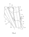
- the curved section 48 of the diffuser pipe 38 has a cross-section expanding rearwardly towards the exit end 41 thereof, such that the section 48 of the diffuser pipe 38 represents a curved fishtail profile with the exit end 41 in a non-round shape, as more clearly shown in FIG. 3 .
- the diffuser pipe 38 defines a central axis 52 extending through the inlet end section 46 in a substantially tangential direction with respect to the annular diffuser body 32 (or in a substantially radial direction with respect to the central axis 31), and then curving through the section 48 so as to extend at the exit end 41 in a substantial axial direction with respect to the engine axis 31.
- the inlet end section 46 may also include a connector 54 of the diffuser pipe 38 which may be a machined part for the connection of the diffuser pipe 38 with an entry portion of a corresponding orifice 34 of the annular diffuser body 32.
- a damper member 50 may be provided between the connector 54 and the entry portion of the orifice 34 to provide a snug attachment of the diffuser pipe 38 to the orifice 34 of the annular diffuser body 32.
- the machined connector 54 is affixed to a remaining section of the inlet end section 46 which is substantially cylindrical at the location of the affix.
- the remaining section of the inlet end section 46 may be integrated and formed together in a fabrication process, with the curved section 48 which has a cross-section rearwardly expanding.
- An imaginary line 56 shown in FIG. 3 indicates a boundary between the substantially truncated conical inlet end section 46 and the curved section 48.
- the diffuser pipe 38 directs the pressurized air flow generated by the impeller 26 and captured by the annular diffuser body 32, which exhibits an extremely high fluid velocity and considerable dynamic pressure of the fluid contributable to the velocity of the fluid, through the rearwardly expanding passage defined by the pipe, to thereby discharge the pressurized air flow to the combustion section 18 at a low velocity and high static pressure.
- the pressurized air flow flowing through the diffuser pipe 38 tends to accumulate a fluid boundary layer on the inner surface of the pipe wall.
- the thickness of the boundary layer progressively increases as the diffuser pipe 38 extends in the downstream direction. Accumulation of the fluid boundary layer reduces the effective cross-sectional flow area of the diffuser pipe 38 such that, at the exit end 41, the boundary layer thickness and the reduced effective flow area significantly weaken further conversion of the dynamic pressure into static pressure of the pressurized air flow.
- a depressed local area 58 in the pipe wall for example of an upstream section of the diffuser pipe 38, is provided such that inner and outer surfaces (not numbered) of the pipe wall in the depressed local area are bent into the diffuser pipe 38.
- the depressed local area may be formed not to impair the diffusing geometry of the pipe passage such that each consecutive cross section area Sn+1 is bigger than or equal to the preceding one Sn, i.e. (Sn+1 ⁇ Sn).
- the depressed local area 58 may be located in the pipe wall of the inlet end section 46 of the diffuser pipe 38, in a location downstream of the connector 54, but immediately upstream of the curved section 48, as shown in FIG. 3 .
- the depressed local area 58 may be located otherwise, such as in a location spanning the imaginary line 56 or adjacent the imaginary line 56 but in the side of the curved diffusing section as indicated by broken lines 58a and 58b in FIG. 3 . It should be noted that the depressed local area shown in the drawings may be exaggerated for illustration and may not be proportional to the size of the real pipe product.
- the depressed local area 58 defines a region of relatively high surface curvature to create a localized acceleration of the pressurized air flow passing through the region where the fluid boundary layer of the air flow can be prone to separation, thereby reducing the accumulation of the fluid boundary layer. Therefore, the depressed local area 58 improves stall margin of the diffuser pipe 38 without significantly compromising overall performance of the diffuser assembly 28, in contrast to conventional annular throat configurations which significantly reduce the flow area of the passage and increases overall flow velocity.
- the depressed local area 58 provides additional local space within a relatively crowded neighbouring area of the diffuser pipes 38, which may be desirable in engine manufacturing.
- the depressed local area 58 may be located in the pipe wall of the diffuser pipe 38 directly facing a portion of the annular diffuser body 32 which defines the orifice 34a adjacent the orifice 34 connected to the diffuser pipe 38 which has the depressed local area 58, thereby providing an enlarged space as indicated by a circular broken line 60 between the diffuser pipe 38 and the annular diffuser body 32, as shown in FIG. 2 .
- this enlarged space 60 may be desirable to ease the challenging job of routing service tubes extending between the diffuser body and the diffuser pipes, which facilitates service tube manufacturing and thus reduces costs.
- the depressed local area 58 in the pipe wall is in a location directly facing a portion of an adjacent diffuser pipe, thereby providing an enlarged space between the at two adjacent diffuser pipes.
- the described depressed local area 58 in the pipe wall may be defined in one or more selected, but up to all of the diffuser pipes 38 connected to the annular diffuser body 32.
- the depressed local areas in the pipe wall of the respective diffuser pipes 38 may be in a same shape and same location which are not necessary but may be for convenience of diffuser pipe fabrication.
- the formation of depressions in local areas of the pipe wall of diffuser pipes may be completed in a pressing process either with existing diffuser pipes without a local depression or in a pipe manufacturing procedure for fabricating new diffuser pipes having depressed local areas.
- diffuser pipe 38 may include more than one depressed local area spaced apart from one another.
- FIG. 5 shows a second depressed local area indicated by broken line 58c located diametrically opposite the depressed local area 58, with respect to the central axis 52 of the diffuser pipe 38.
- the diffuser pipes and diffuser assembly described in the embodiments are used in a turbofan gas turbine engine as illustrated in the drawings as an exemplary application, will be applicable to any other suitable types of engines.
- the diffuser pipes may have a machined connector, or may otherwise be formed of sheet metal without a machined connector. Still other modifications which fall within the scope of the described subject matter will be apparent to those skilled in the art, in light of a review of this disclosure, and such modifications are intended to fall within the appended claims.
Abstract
Description
- The described subject matter relates generally to gas turbine engines, and more particularly, to an improved compressor diffuser assembly for gas turbine engines.
- Typically, gas turbine engines include a compressor section which delivers pressurized air to a continuous flow combustor. A diffuser assembly is usually provided in the compressor section of the engine for the purpose of converting the dynamic head of the pressurized air generated by the compressor into static pressure. For example, diffuser assemblies of some types may employ diffuser pipes each having a cross-section expanding rearwardly towards an exit end of the pipe, to direct the pressurized air therethrough and discharge the pressurized air to the combustion section of the engine at a low velocity and high static pressure. Ideally, it is desirable to convert the dynamic head of the pressurized air generated by the compressor into static pressure at the combustion section without any loss of total pressure. However, the efficiency or effectiveness of diffuser assemblies known in the art is less than satisfactory.
- Accordingly, there is a need to provide an improved compressor diffuser assembly for gas turbine engines.
- In one aspect, the described subject matter provides a diffuser pipe assembly of a gas turbine engine including a plurality of circumferentially spaced diffuser pipes, each diffuser pipe comprising a substantially truncated conical inlet end section defining an inlet end of the diffuser pipe and a curved section defining an exit end of the diffuser pipe to direct a pressurized airflow from the inlet end through the diffuser pipe to the exit end, the curved section having a cross-section expanding rearwardly towards the exit end such that the curved section presents a curved fishtail profile, the inlet end section defining a depressed local area in a pipe wall of the inlet end section such that both inner and outer surfaces of the pipe wall in the depressed local area are bent into the diffuser pipe, wherein each consecutive cross section area Sn+1 is bigger than or equal to a preceding one Sn.
- In another aspect, the described subject matter provides a diffuser assembly for a gas turbine engine comprising an annular diffuser body having a plurality of orifices disposed circumferentially around an outer periphery of the diffuser body; a plurality of diffuser pipes each having an inlet end connected to one of the orifices of the diffuser body, each of the diffuser pipes including an inlet end section in a substantially round cross section defining the inlet end and a curved section defining an exit end of the diffuser pipe to direct a pressurized airflow from the inlet end through a passage to the exit end, the curved section having a cross-section expanding rearwardly towards the exit end such that the curved section presents a curved fishtail profile; and wherein at least one of the diffuser pipes defines a depressed local area in a pipe wall of an upstream section of the at least one diffuser pipe such that both inner and outer surfaces of the pipe wall in the depressed local area are bent into the at least one diffuser pipe, wherein each consecutive cross section area Sn+1 is bigger than or equal to the preceding one Sn.
- Further details of these and other aspects of the described subject matter will be apparent from the detailed description and drawings included below.
- Reference is now made to the accompanying drawings depicting aspects of the described subject matter, in which:
-
FIG. 1 is a schematic cross-sectional view of a turbofan gas turbine engine showing an exemplary application of the described subject matter; -
FIG. 2 is a partial cross-sectional view of a compressor diffuser assembly used in the engine ofFIG. 1 ; -
FIG. 3 is a perspective view of a diffuser pipe used in the compressor diffuser assembly ofFIG. 2 ; -
FIG. 4 is an enlarged cross-sectional view of an end portion of the diffuser pipe, as shown in the circled area 4 inFIG. 3 ; and -
FIG. 5 is a cross-sectional view of the diffuser pipe, taken along line 5-5 ofFIG. 4 . - It will be noted that throughout the appended drawings, like features are identified by like reference numerals.
- Referring to
FIG. 1 , a turbofan gas turbine engine incorporates an embodiment of the described subject matter, presented as an example of the application of the described subject matter, and includes a housing or anacelle 10 which contains afan section 12 and at least a major section of acore engine 14. Thecore engine 14 comprises in flow series, acompressor section 16, acombustion section 18, aturbine section 20, and anexhaust section 22. Theturbine section 20 and thecompressor section 16 comprise multiple stages. At least one turbine (not indicated) within theturbine section 20 is rotationally connected to a final stage of thecompressor section 16 by ashaft 24. - The final stage of the
compressor section 16 is a rotatingimpeller 26 in flow communication withcombustion section 18 through adiffuser assembly 28. Theimpeller 26 draws air axially, and rotation of theimpeller 26 about acentral axis 31 of the engine increases the velocity of air flow as input air is directed over impeller vanes (not numbered), to flow in a radially outward direction under centrifugal forces. Thediffuser assembly 28 redirects the radial flow of air exiting theimpeller 26 to an annular axial flow for presentation to acombustor 30. Thediffuser assembly 28 also reduces the velocity and increases the static pressure of the air flow when the air flow is directed therethrough. - Referring to
FIGS. 1-5 , thecompressor diffuser assembly 28 includes anannular diffuser body 32 which is a machined ring having a plurality of substantiallytangential orifices 34 disposed circumferentially spaced apart in anouter periphery 36 of thediffuser body 32, and extending inwardly and substantially tangentially through theannular diffuser body 32. Each of theorifices 34 is intersected by two adjacent orifices in an asymmetrical configuration (one adjacent orifice indicated as 34a is shown inFIG. 2 ). With such a configuration, theannular diffuser body 32 is positioned to surround a periphery of theimpeller 26 for capturing the pressurized air flow and directing same radially and outwardly through the substantiallytangential orifices 34. - The
compressor diffuser assembly 28 further includes a plurality of diffuser pipes 38 (only one shown inFIG. 2 ) connected to therespective orifices 34 of theannular diffuser body 32, for example, by being inserted at aninlet end 40 of thediffuser pipe 38 into theindividual orifices 34 of theannular diffuser body 32. Each of thediffuser pipes 38 has a cross-section expanding rearwardly towards anexit end 41 thereof, which is generally referred to as "fishtail" pipes. Thediffuser pipes 38 define respective circumferentially spaced passages (not numbered) to further direct the pressurized air flow from the individual substantiallytangential orifices 34 through the rearwardly expanding cross-section, thereby discharging the pressurized air flow to thecombustion section 18 at a low velocity and high static pressure. - All
orifices 34 anddiffuser pipes 38 are substantially identical, respectively, and therefore only one orifice and one diffuser pipe are described in detail for convenience of description. However, a depressed local area in a pipe wall may be provided to one or more, up to alldiffuser pipes 38 of thediffuser assembly 28, which will be further described hereinafter. - The
diffuser pipe 38 includes aninlet end section 46 defining theinlet end 40 and having a substantially truncated conical profile such that theinlet end section 46 has a round cross-section slightly rearwardly expanding, as is more clearly shown inFIG. 4 . - The remaining section of the
diffuser pipe 38, referred to as asection 48, has a curved profile for directing the air flow passing therethrough, from a radial direction (or a substantially tangential direction of the annular diffuser body 32) to a substantially axial direction of the engine. Thecurved section 48 of thediffuser pipe 38 has a cross-section expanding rearwardly towards theexit end 41 thereof, such that thesection 48 of thediffuser pipe 38 represents a curved fishtail profile with theexit end 41 in a non-round shape, as more clearly shown inFIG. 3 . Therefore, thediffuser pipe 38 defines acentral axis 52 extending through theinlet end section 46 in a substantially tangential direction with respect to the annular diffuser body 32 (or in a substantially radial direction with respect to the central axis 31), and then curving through thesection 48 so as to extend at theexit end 41 in a substantial axial direction with respect to theengine axis 31. - The
inlet end section 46 may also include aconnector 54 of thediffuser pipe 38 which may be a machined part for the connection of thediffuser pipe 38 with an entry portion of acorresponding orifice 34 of theannular diffuser body 32. Adamper member 50 may be provided between theconnector 54 and the entry portion of theorifice 34 to provide a snug attachment of thediffuser pipe 38 to theorifice 34 of theannular diffuser body 32. Themachined connector 54 is affixed to a remaining section of theinlet end section 46 which is substantially cylindrical at the location of the affix. The remaining section of theinlet end section 46 may be integrated and formed together in a fabrication process, with thecurved section 48 which has a cross-section rearwardly expanding. Animaginary line 56 shown inFIG. 3 indicates a boundary between the substantially truncated conicalinlet end section 46 and thecurved section 48. - As described, the
diffuser pipe 38 directs the pressurized air flow generated by theimpeller 26 and captured by theannular diffuser body 32, which exhibits an extremely high fluid velocity and considerable dynamic pressure of the fluid contributable to the velocity of the fluid, through the rearwardly expanding passage defined by the pipe, to thereby discharge the pressurized air flow to thecombustion section 18 at a low velocity and high static pressure. However, the pressurized air flow flowing through thediffuser pipe 38 tends to accumulate a fluid boundary layer on the inner surface of the pipe wall. The thickness of the boundary layer progressively increases as thediffuser pipe 38 extends in the downstream direction. Accumulation of the fluid boundary layer reduces the effective cross-sectional flow area of thediffuser pipe 38 such that, at theexit end 41, the boundary layer thickness and the reduced effective flow area significantly weaken further conversion of the dynamic pressure into static pressure of the pressurized air flow. - In accordance with one embodiment, a depressed
local area 58 in the pipe wall, for example of an upstream section of thediffuser pipe 38, is provided such that inner and outer surfaces (not numbered) of the pipe wall in the depressed local area are bent into thediffuser pipe 38. The depressed local area may be formed not to impair the diffusing geometry of the pipe passage such that each consecutive cross section area Sn+1 is bigger than or equal to the preceding one Sn, i.e. (Sn+1≥Sn). For example, example, the depressedlocal area 58 may be located in the pipe wall of theinlet end section 46 of thediffuser pipe 38, in a location downstream of theconnector 54, but immediately upstream of thecurved section 48, as shown inFIG. 3 . Nevertheless, the depressedlocal area 58 may be located otherwise, such as in a location spanning theimaginary line 56 or adjacent theimaginary line 56 but in the side of the curved diffusing section as indicated bybroken lines FIG. 3 . It should be noted that the depressed local area shown in the drawings may be exaggerated for illustration and may not be proportional to the size of the real pipe product. - The depressed
local area 58 defines a region of relatively high surface curvature to create a localized acceleration of the pressurized air flow passing through the region where the fluid boundary layer of the air flow can be prone to separation, thereby reducing the accumulation of the fluid boundary layer. Therefore, the depressedlocal area 58 improves stall margin of thediffuser pipe 38 without significantly compromising overall performance of thediffuser assembly 28, in contrast to conventional annular throat configurations which significantly reduce the flow area of the passage and increases overall flow velocity. - In another aspect, the depressed
local area 58 provides additional local space within a relatively crowded neighbouring area of thediffuser pipes 38, which may be desirable in engine manufacturing. For example, the depressedlocal area 58 according to one embodiment, may be located in the pipe wall of thediffuser pipe 38 directly facing a portion of theannular diffuser body 32 which defines theorifice 34a adjacent theorifice 34 connected to thediffuser pipe 38 which has the depressedlocal area 58, thereby providing an enlarged space as indicated by a circularbroken line 60 between thediffuser pipe 38 and theannular diffuser body 32, as shown inFIG. 2 . In some types of diffuser assemblies, this enlargedspace 60 may be desirable to ease the challenging job of routing service tubes extending between the diffuser body and the diffuser pipes, which facilitates service tube manufacturing and thus reduces costs. - Alternatively, in some types of diffuser assemblies the depressed
local area 58 in the pipe wall is in a location directly facing a portion of an adjacent diffuser pipe, thereby providing an enlarged space between the at two adjacent diffuser pipes. - The described depressed
local area 58 in the pipe wall may be defined in one or more selected, but up to all of thediffuser pipes 38 connected to theannular diffuser body 32. The depressed local areas in the pipe wall of therespective diffuser pipes 38 may be in a same shape and same location which are not necessary but may be for convenience of diffuser pipe fabrication. - The formation of depressions in local areas of the pipe wall of diffuser pipes may be completed in a pressing process either with existing diffuser pipes without a local depression or in a pipe manufacturing procedure for fabricating new diffuser pipes having depressed local areas.
- Alternatively,
diffuser pipe 38 may include more than one depressed local area spaced apart from one another. For example,FIG. 5 shows a second depressed local area indicated bybroken line 58c located diametrically opposite the depressedlocal area 58, with respect to thecentral axis 52 of thediffuser pipe 38. - The above description is meant to be exemplary only, and one skilled in the art will recognize that changes may be made to the embodiments described without departure from the scope of the described subject matter. For example, the diffuser pipes and diffuser assembly described in the embodiments are used in a turbofan gas turbine engine as illustrated in the drawings as an exemplary application, will be applicable to any other suitable types of engines. The diffuser pipes may have a machined connector, or may otherwise be formed of sheet metal without a machined connector. Still other modifications which fall within the scope of the described subject matter will be apparent to those skilled in the art, in light of a review of this disclosure, and such modifications are intended to fall within the appended claims.
Claims (15)
- A diffuser assembly (28) for a gas turbine engine comprising:an annular diffuser body (32) having a plurality of orifices (34) disposed circumferentially around an outer periphery (36) of the diffuser body (32);a plurality of diffuser pipes (38) each having an inlet end (40) connected to one of the orifices (34) of the diffuser body (32), each of the diffuser pipes (38) including an inlet end section (46) in a substantially round cross section defining the inlet end (40) and a curved section (48) defining an exit end (41) of the diffuser pipe (38) to direct a pressurized airflow from the inlet end (40) through a passage to the exit end (41), the curved section (48) having a cross-section expanding rearwardly towards the exit end (41) such that the curved section (48) presents a curved fishtail profile; andwherein at least one of the diffuser pipes (38) defines a depressed local area (58) in a pipe wall of an upstream section of the at least one diffuser pipe (38) such that both inner and outer surfaces of the pipe wall in the depressed local area (58) are bent into the at least one diffuser pipe (38), wherein each consecutive cross section area Sn+1 is bigger than or equal to the preceding one Sn.
- The diffuser assembly (28) as defined in claim 1 wherein a central axis (52) of each of the diffuser pipes (38) extends through the inlet end section (46) in a substantially tangential direction with respect to the annular diffuser body (32) and extends at the exit end (41) in a substantially axial direction with respect to a central axis (31) of the engine.
- The diffuser assembly (28) as defined in claim 1 or 2 wherein the inlet end section (46) of each of the diffuser pipes (38) comprises a connector (54) defining the inlet end (40) of the diffuser pipe (38) for connection with said one of the orifices (34) of the diffuser body (32).
- The diffuser assembly (28) as defined in claim 3 wherein the depressed local area (58) in the pipe wall of the at least one diffuser pipe (38) is located downstream of the connector (54).
- The diffuser assembly (28) as defined in any preceding claim wherein the depressed local area (58) in the pipe wall of the at least one diffuser pipe (38) is located in the inlet end section (46), immediately upstream of the curved section (48).
- The diffuser assembly (28) as defined in any preceding claim wherein each of the diffuser pipes (38) comprises the depressed local area (58) in the pipe wall of the inlet end section (46).
- The diffuser assembly (28) as defined in any of claims 1 to 4 wherein the depressed local area (58a or 58b) in the pipe wall of the at least one diffuser pipe (38) is located in the curved section (48).
- The diffuser assembly (28) as defined in any preceding claim wherein the at least one diffuser pipe (38) comprises a second depressed local area (58c) in the pipe wall of the inlet end section (46), circumferentially spaced apart from said depressed local area (58) with respect to a central axis (52) of the diffuser pipe (38).
- The diffuser assembly (28) as defined in claim 8 wherein the second depressed local area (58c) located diametrically opposite to said depressed local area (58) with respect to a central axis (52) of the at least one diffuser pipe (38).
- The diffuser assembly (28) as defined in any preceding claim wherein the depressed local area (58) in the pipe wall of the at least one diffuser pipe (38) is in a location directly facing a portion of the diffuser body (32) which defines one (34a) of the orifices adjacent the orifice (34) connected to the at least one diffuser pipe (38), thereby providing an enlarged space (60) between the at least one diffuser pipe (38) and the diffuser body (32).
- The diffuser assembly (28) as defined in any preceding claim wherein the depressed local area (58) in the pipe wall of the at least one diffuser pipe (3 8) is in a location directly facing a portion of the adjacent diffuser pipe (38), thereby providing an enlarged space between the at least one diffuser pipe (38) and the adjacent diffuser pipe (38).
- A diffuser pipe assembly (28) of a gas turbine engine including a plurality of circumferentially spaced diffuser pipes (38), each diffuser pipe (38) comprising a substantially truncated conical inlet end section (46) defining an inlet end (40) of the diffuser pipe (38) and a curved section (48) defining an exit end (41) of the diffuser pipe (38) to direct a pressurized airflow from the inlet end (40) through the diffuser pipe (38) to the exit end (41), the curved section (48) having a cross-section expanding rearwardly towards the exit end (41) such that the curved section (48) presents a curved fishtail profile, the inlet end section (46) defining a depressed local area (58) in a pipe wall of the inlet end section (46) such that both inner and outer surfaces of the pipe wall in the depressed local area (58) are bent into the diffuser pipe (38), wherein each consecutive cross section area Sn+1 is bigger than or equal to a preceding one Sn.
- The diffuser pipe assembly (28) as defined in claim 12 wherein the depressed local area (58) in the pipe wall of the inlet end section (46) is located immediately upstream of the curved section (48), or in the curved section (48).
- The diffuser pipe assembly (28) as defined in claim 12 or 13 wherein the inlet end section (46) comprises a connector (54) defining the inlet end (40) and wherein the depressed local area (58) in the pipe wall of the inlet end section (46) is located downstream of the connector (54).
- The diffuser pipe assembly (28) as defined in claim 12, 13 or 14 comprising a second depressed local area (58c) in the pipe wall of the inlet end section (46), circumferentially spaced apart from said depressed local area (58) with respect to a central axis (52) of the diffuser pipe (38), for example located diametrically opposite to said depressed local area (58) with respect to a central axis (52) of the diffuser pipe (38).
Applications Claiming Priority (1)
| Application Number | Priority Date | Filing Date | Title |
|---|---|---|---|
| PCT/RU2011/000473 WO2013002667A1 (en) | 2011-06-30 | 2011-06-30 | Diffuser pipe and assembly for gas turbine engine |
Publications (2)
| Publication Number | Publication Date |
|---|---|
| EP2541069A1 true EP2541069A1 (en) | 2013-01-02 |
| EP2541069B1 EP2541069B1 (en) | 2016-05-04 |
Family
ID=46419934
Family Applications (1)
| Application Number | Title | Priority Date | Filing Date |
|---|---|---|---|
| EP12173659.9A Active EP2541069B1 (en) | 2011-06-30 | 2012-06-26 | Radial compressor diffuser pipe with bump to reduce boundary layer accumulation |
Country Status (4)
| Country | Link |
|---|---|
| US (1) | US8425188B2 (en) |
| EP (1) | EP2541069B1 (en) |
| RU (1) | RU2013154700A (en) |
| WO (1) | WO2013002667A1 (en) |
Cited By (1)
| Publication number | Priority date | Publication date | Assignee | Title |
|---|---|---|---|---|
| EP4163499A1 (en) * | 2021-10-08 | 2023-04-12 | Honeywell International Inc. | Diffuser and deswirl system with integral tangential on-board injector for engine |
Families Citing this family (12)
| Publication number | Priority date | Publication date | Assignee | Title |
|---|---|---|---|---|
| US9874223B2 (en) | 2013-06-17 | 2018-01-23 | Pratt & Whitney Canada Corp. | Diffuser pipe for a gas turbine engine and method for manufacturing same |
| DE102015219556A1 (en) | 2015-10-08 | 2017-04-13 | Rolls-Royce Deutschland Ltd & Co Kg | Diffuser for radial compressor, centrifugal compressor and turbo machine with centrifugal compressor |
| US10544693B2 (en) | 2016-06-15 | 2020-01-28 | Honeywell International Inc. | Service routing configuration for a gas turbine engine diffuser system |
| US10718222B2 (en) | 2017-03-27 | 2020-07-21 | General Electric Company | Diffuser-deswirler for a gas turbine engine |
| US10823195B2 (en) * | 2018-04-17 | 2020-11-03 | Pratt & Whitney Canada Corp. | Diffuser pipe with non-axisymmetric end wall |
| US11098650B2 (en) | 2018-08-10 | 2021-08-24 | Pratt & Whitney Canada Corp. | Compressor diffuser with diffuser pipes having aero-dampers |
| US10823196B2 (en) * | 2018-08-10 | 2020-11-03 | Pratt & Whitney Canada Corp. | Compressor diffuser with diffuser pipes varying in natural vibration frequencies |
| US11098730B2 (en) | 2019-04-12 | 2021-08-24 | Rolls-Royce Corporation | Deswirler assembly for a centrifugal compressor |
| US11286951B2 (en) * | 2019-05-21 | 2022-03-29 | Pratt & Whitney Canada Corp. | Diffuser pipe with exit scallops |
| US11286952B2 (en) | 2020-07-14 | 2022-03-29 | Rolls-Royce Corporation | Diffusion system configured for use with centrifugal compressor |
| US11441516B2 (en) | 2020-07-14 | 2022-09-13 | Rolls-Royce North American Technologies Inc. | Centrifugal compressor assembly for a gas turbine engine with deswirler having sealing features |
| US11578654B2 (en) | 2020-07-29 | 2023-02-14 | Rolls-Royce North American Technologies Inc. | Centrifical compressor assembly for a gas turbine engine |
Citations (5)
| Publication number | Priority date | Publication date | Assignee | Title |
|---|---|---|---|---|
| US2735612A (en) * | 1956-02-21 | hausmann | ||
| US3289921A (en) * | 1965-10-08 | 1966-12-06 | Caterpillar Tractor Co | Vaneless diffuser |
| US3578264A (en) * | 1968-07-09 | 1971-05-11 | Battelle Development Corp | Boundary layer control of flow separation and heat exchange |
| US20060104809A1 (en) * | 2004-11-17 | 2006-05-18 | Pratt & Whitney Canada Corp. | Low cost diffuser assembly for gas turbine engine |
| US20100278643A1 (en) * | 2009-04-30 | 2010-11-04 | Leblanc Andre | Centrifugal compressor vane diffuser wall contouring |
Family Cites Families (19)
| Publication number | Priority date | Publication date | Assignee | Title |
|---|---|---|---|---|
| US3144202A (en) | 1960-11-19 | 1964-08-11 | Helmbold Theodor | Stabilizing devices for generating and guiding potential whirls |
| US3644055A (en) | 1969-10-02 | 1972-02-22 | Ingersoll Rand Co | Fluid-motion apparatus |
| GB1573926A (en) | 1976-03-24 | 1980-08-28 | Rolls Royce | Fluid flow diffuser |
| US4796429A (en) | 1976-11-15 | 1989-01-10 | General Motors Corporation | Combustor diffuser |
| US4100732A (en) | 1976-12-02 | 1978-07-18 | General Electric Company | Centrifugal compressor advanced dump diffuser |
| US4272955A (en) | 1979-06-28 | 1981-06-16 | General Electric Company | Diffusing means |
| DE3168712D1 (en) | 1980-03-10 | 1985-03-21 | Rolls Royce | DIFFUSION APPARATUS |
| US4431374A (en) | 1981-02-23 | 1984-02-14 | Teledyne Industries, Inc. | Vortex controlled radial diffuser for centrifugal compressor |
| PL143757B1 (en) | 1984-03-27 | 1988-03-31 | Inst Lotnictwa | Ultrasonic channel-type diffuser in particular a radial one |
| SU1308781A1 (en) * | 1985-11-26 | 1987-05-07 | Предприятие П/Я М-5727 | Vaneless diffuser of centrifugal compressor |
| US4979361A (en) | 1989-07-13 | 1990-12-25 | United Technologies Corporation | Stepped diffuser |
| US5387081A (en) | 1993-12-09 | 1995-02-07 | Pratt & Whitney Canada, Inc. | Compressor diffuser |
| GB9415685D0 (en) | 1994-08-03 | 1994-09-28 | Rolls Royce Plc | A gas turbine engine and a diffuser therefor |
| RU2103560C1 (en) * | 1995-12-20 | 1998-01-27 | Научно-производственное объединение энергетического машиностроения им.акад.В.П.Глушко | Annular diffuser of centrifugal pump stator |
| US6471475B1 (en) | 2000-07-14 | 2002-10-29 | Pratt & Whitney Canada Corp. | Integrated duct diffuser |
| US6540481B2 (en) | 2001-04-04 | 2003-04-01 | General Electric Company | Diffuser for a centrifugal compressor |
| US6647730B2 (en) | 2001-10-31 | 2003-11-18 | Pratt & Whitney Canada Corp. | Turbine engine having turbine cooled with diverted compressor intermediate pressure air |
| US6589015B1 (en) | 2002-05-08 | 2003-07-08 | Pratt & Whitney Canada Corp. | Discrete passage diffuser |
| US7101151B2 (en) | 2003-09-24 | 2006-09-05 | General Electric Company | Diffuser for centrifugal compressor |
-
2011
- 2011-06-30 WO PCT/RU2011/000473 patent/WO2013002667A1/en active Application Filing
- 2011-06-30 RU RU2013154700/06A patent/RU2013154700A/en unknown
-
2012
- 2012-06-07 US US13/490,860 patent/US8425188B2/en active Active
- 2012-06-26 EP EP12173659.9A patent/EP2541069B1/en active Active
Patent Citations (6)
| Publication number | Priority date | Publication date | Assignee | Title |
|---|---|---|---|---|
| US2735612A (en) * | 1956-02-21 | hausmann | ||
| US3289921A (en) * | 1965-10-08 | 1966-12-06 | Caterpillar Tractor Co | Vaneless diffuser |
| US3578264A (en) * | 1968-07-09 | 1971-05-11 | Battelle Development Corp | Boundary layer control of flow separation and heat exchange |
| US3578264B1 (en) * | 1968-07-09 | 1991-11-19 | Univ Michigan | |
| US20060104809A1 (en) * | 2004-11-17 | 2006-05-18 | Pratt & Whitney Canada Corp. | Low cost diffuser assembly for gas turbine engine |
| US20100278643A1 (en) * | 2009-04-30 | 2010-11-04 | Leblanc Andre | Centrifugal compressor vane diffuser wall contouring |
Cited By (1)
| Publication number | Priority date | Publication date | Assignee | Title |
|---|---|---|---|---|
| EP4163499A1 (en) * | 2021-10-08 | 2023-04-12 | Honeywell International Inc. | Diffuser and deswirl system with integral tangential on-board injector for engine |
Also Published As
| Publication number | Publication date |
|---|---|
| US8425188B2 (en) | 2013-04-23 |
| EP2541069B1 (en) | 2016-05-04 |
| RU2013154700A (en) | 2015-08-10 |
| US20130000308A1 (en) | 2013-01-03 |
| WO2013002667A1 (en) | 2013-01-03 |
Similar Documents
| Publication | Publication Date | Title |
|---|---|---|
| EP2541069B1 (en) | Radial compressor diffuser pipe with bump to reduce boundary layer accumulation | |
| US10502231B2 (en) | Diffuser pipe with vortex generators | |
| JP6017755B2 (en) | Exhaust gas diffuser | |
| EP1214522B1 (en) | Deswirler system for centrifugal compressor | |
| CA2701312C (en) | Centrifugal compressor vane diffuser wall contouring | |
| KR100910439B1 (en) | Diagonal flow turbine or radial turbine | |
| US8038392B2 (en) | Axial diffuser for a centrifugal compressor | |
| EP2617961A1 (en) | Turbine scroll structure | |
| JP5535562B2 (en) | Discharge scroll and turbo machine | |
| JP2010216321A (en) | Moving blade of steam turbine, and steam turbine using the same | |
| US20160115971A1 (en) | Diffuser pipe with splitter vane | |
| US11859543B2 (en) | Diffuser pipe with exit flare | |
| US10823195B2 (en) | Diffuser pipe with non-axisymmetric end wall | |
| CA3082693A1 (en) | Diffuser pipe with axially-directed exit | |
| US8221073B2 (en) | Exhaust gas discharge system and plenum | |
| US8870532B2 (en) | Exhaust hood diffuser | |
| US11702962B2 (en) | Steam turbine configured to recover static pressure of steam in diffuser | |
| US11286951B2 (en) | Diffuser pipe with exit scallops | |
| US20130022444A1 (en) | Low pressure turbine exhaust diffuser with turbulators |
Legal Events
| Date | Code | Title | Description |
|---|---|---|---|
| PUAI | Public reference made under article 153(3) epc to a published international application that has entered the european phase |
Free format text: ORIGINAL CODE: 0009012 |
|
| AK | Designated contracting states |
Kind code of ref document: A1 Designated state(s): AL AT BE BG CH CY CZ DE DK EE ES FI FR GB GR HR HU IE IS IT LI LT LU LV MC MK MT NL NO PL PT RO RS SE SI SK SM TR |
|
| AX | Request for extension of the european patent |
Extension state: BA ME |
|
| 17P | Request for examination filed |
Effective date: 20130627 |
|
| RBV | Designated contracting states (corrected) |
Designated state(s): AL AT BE BG CH CY CZ DE DK EE ES FI FR GB GR HR HU IE IS IT LI LT LU LV MC MK MT NL NO PL PT RO RS SE SI SK SM TR |
|
| GRAP | Despatch of communication of intention to grant a patent |
Free format text: ORIGINAL CODE: EPIDOSNIGR1 |
|
| RIC1 | Information provided on ipc code assigned before grant |
Ipc: F04D 29/68 20060101ALI20151216BHEP Ipc: F04D 29/44 20060101AFI20151216BHEP |
|
| INTG | Intention to grant announced |
Effective date: 20160112 |
|
| GRAS | Grant fee paid |
Free format text: ORIGINAL CODE: EPIDOSNIGR3 |
|
| GRAA | (expected) grant |
Free format text: ORIGINAL CODE: 0009210 |
|
| AK | Designated contracting states |
Kind code of ref document: B1 Designated state(s): AL AT BE BG CH CY CZ DE DK EE ES FI FR GB GR HR HU IE IS IT LI LT LU LV MC MK MT NL NO PL PT RO RS SE SI SK SM TR |
|
| REG | Reference to a national code |
Ref country code: GB Ref legal event code: FG4D |
|
| REG | Reference to a national code |
Ref country code: CH Ref legal event code: EP |
|
| REG | Reference to a national code |
Ref country code: AT Ref legal event code: REF Ref document number: 797171 Country of ref document: AT Kind code of ref document: T Effective date: 20160515 |
|
| REG | Reference to a national code |
Ref country code: FR Ref legal event code: PLFP Year of fee payment: 5 |
|
| REG | Reference to a national code |
Ref country code: IE Ref legal event code: FG4D |
|
| REG | Reference to a national code |
Ref country code: DE Ref legal event code: R096 Ref document number: 602012017994 Country of ref document: DE |
|
| REG | Reference to a national code |
Ref country code: NL Ref legal event code: MP Effective date: 20160504 |
|
| REG | Reference to a national code |
Ref country code: LT Ref legal event code: MG4D |
|
| PG25 | Lapsed in a contracting state [announced via postgrant information from national office to epo] |
Ref country code: FI Free format text: LAPSE BECAUSE OF FAILURE TO SUBMIT A TRANSLATION OF THE DESCRIPTION OR TO PAY THE FEE WITHIN THE PRESCRIBED TIME-LIMIT Effective date: 20160504 Ref country code: NL Free format text: LAPSE BECAUSE OF FAILURE TO SUBMIT A TRANSLATION OF THE DESCRIPTION OR TO PAY THE FEE WITHIN THE PRESCRIBED TIME-LIMIT Effective date: 20160504 Ref country code: LT Free format text: LAPSE BECAUSE OF FAILURE TO SUBMIT A TRANSLATION OF THE DESCRIPTION OR TO PAY THE FEE WITHIN THE PRESCRIBED TIME-LIMIT Effective date: 20160504 Ref country code: NO Free format text: LAPSE BECAUSE OF FAILURE TO SUBMIT A TRANSLATION OF THE DESCRIPTION OR TO PAY THE FEE WITHIN THE PRESCRIBED TIME-LIMIT Effective date: 20160804 |
|
| REG | Reference to a national code |
Ref country code: AT Ref legal event code: MK05 Ref document number: 797171 Country of ref document: AT Kind code of ref document: T Effective date: 20160504 |
|
| PG25 | Lapsed in a contracting state [announced via postgrant information from national office to epo] |
Ref country code: HR Free format text: LAPSE BECAUSE OF FAILURE TO SUBMIT A TRANSLATION OF THE DESCRIPTION OR TO PAY THE FEE WITHIN THE PRESCRIBED TIME-LIMIT Effective date: 20160504 Ref country code: SE Free format text: LAPSE BECAUSE OF FAILURE TO SUBMIT A TRANSLATION OF THE DESCRIPTION OR TO PAY THE FEE WITHIN THE PRESCRIBED TIME-LIMIT Effective date: 20160504 Ref country code: ES Free format text: LAPSE BECAUSE OF FAILURE TO SUBMIT A TRANSLATION OF THE DESCRIPTION OR TO PAY THE FEE WITHIN THE PRESCRIBED TIME-LIMIT Effective date: 20160504 Ref country code: GR Free format text: LAPSE BECAUSE OF FAILURE TO SUBMIT A TRANSLATION OF THE DESCRIPTION OR TO PAY THE FEE WITHIN THE PRESCRIBED TIME-LIMIT Effective date: 20160805 Ref country code: PT Free format text: LAPSE BECAUSE OF FAILURE TO SUBMIT A TRANSLATION OF THE DESCRIPTION OR TO PAY THE FEE WITHIN THE PRESCRIBED TIME-LIMIT Effective date: 20160905 Ref country code: RS Free format text: LAPSE BECAUSE OF FAILURE TO SUBMIT A TRANSLATION OF THE DESCRIPTION OR TO PAY THE FEE WITHIN THE PRESCRIBED TIME-LIMIT Effective date: 20160504 Ref country code: LV Free format text: LAPSE BECAUSE OF FAILURE TO SUBMIT A TRANSLATION OF THE DESCRIPTION OR TO PAY THE FEE WITHIN THE PRESCRIBED TIME-LIMIT Effective date: 20160504 |
|
| PG25 | Lapsed in a contracting state [announced via postgrant information from national office to epo] |
Ref country code: BE Free format text: LAPSE BECAUSE OF NON-PAYMENT OF DUE FEES Effective date: 20160630 Ref country code: IT Free format text: LAPSE BECAUSE OF FAILURE TO SUBMIT A TRANSLATION OF THE DESCRIPTION OR TO PAY THE FEE WITHIN THE PRESCRIBED TIME-LIMIT Effective date: 20160504 |
|
| PG25 | Lapsed in a contracting state [announced via postgrant information from national office to epo] |
Ref country code: SK Free format text: LAPSE BECAUSE OF FAILURE TO SUBMIT A TRANSLATION OF THE DESCRIPTION OR TO PAY THE FEE WITHIN THE PRESCRIBED TIME-LIMIT Effective date: 20160504 Ref country code: CZ Free format text: LAPSE BECAUSE OF FAILURE TO SUBMIT A TRANSLATION OF THE DESCRIPTION OR TO PAY THE FEE WITHIN THE PRESCRIBED TIME-LIMIT Effective date: 20160504 Ref country code: RO Free format text: LAPSE BECAUSE OF FAILURE TO SUBMIT A TRANSLATION OF THE DESCRIPTION OR TO PAY THE FEE WITHIN THE PRESCRIBED TIME-LIMIT Effective date: 20160504 Ref country code: EE Free format text: LAPSE BECAUSE OF FAILURE TO SUBMIT A TRANSLATION OF THE DESCRIPTION OR TO PAY THE FEE WITHIN THE PRESCRIBED TIME-LIMIT Effective date: 20160504 Ref country code: DK Free format text: LAPSE BECAUSE OF FAILURE TO SUBMIT A TRANSLATION OF THE DESCRIPTION OR TO PAY THE FEE WITHIN THE PRESCRIBED TIME-LIMIT Effective date: 20160504 |
|
| REG | Reference to a national code |
Ref country code: CH Ref legal event code: PL |
|
| REG | Reference to a national code |
Ref country code: DE Ref legal event code: R097 Ref document number: 602012017994 Country of ref document: DE |
|
| PG25 | Lapsed in a contracting state [announced via postgrant information from national office to epo] |
Ref country code: AT Free format text: LAPSE BECAUSE OF FAILURE TO SUBMIT A TRANSLATION OF THE DESCRIPTION OR TO PAY THE FEE WITHIN THE PRESCRIBED TIME-LIMIT Effective date: 20160504 Ref country code: BE Free format text: LAPSE BECAUSE OF FAILURE TO SUBMIT A TRANSLATION OF THE DESCRIPTION OR TO PAY THE FEE WITHIN THE PRESCRIBED TIME-LIMIT Effective date: 20160504 Ref country code: SM Free format text: LAPSE BECAUSE OF FAILURE TO SUBMIT A TRANSLATION OF THE DESCRIPTION OR TO PAY THE FEE WITHIN THE PRESCRIBED TIME-LIMIT Effective date: 20160504 Ref country code: PL Free format text: LAPSE BECAUSE OF FAILURE TO SUBMIT A TRANSLATION OF THE DESCRIPTION OR TO PAY THE FEE WITHIN THE PRESCRIBED TIME-LIMIT Effective date: 20160504 |
|
| PLBE | No opposition filed within time limit |
Free format text: ORIGINAL CODE: 0009261 |
|
| STAA | Information on the status of an ep patent application or granted ep patent |
Free format text: STATUS: NO OPPOSITION FILED WITHIN TIME LIMIT |
|
| REG | Reference to a national code |
Ref country code: IE Ref legal event code: MM4A |
|
| PG25 | Lapsed in a contracting state [announced via postgrant information from national office to epo] |
Ref country code: MC Free format text: LAPSE BECAUSE OF FAILURE TO SUBMIT A TRANSLATION OF THE DESCRIPTION OR TO PAY THE FEE WITHIN THE PRESCRIBED TIME-LIMIT Effective date: 20160504 |
|
| 26N | No opposition filed |
Effective date: 20170207 |
|
| PG25 | Lapsed in a contracting state [announced via postgrant information from national office to epo] |
Ref country code: LI Free format text: LAPSE BECAUSE OF NON-PAYMENT OF DUE FEES Effective date: 20160630 Ref country code: CH Free format text: LAPSE BECAUSE OF NON-PAYMENT OF DUE FEES Effective date: 20160630 |
|
| REG | Reference to a national code |
Ref country code: FR Ref legal event code: PLFP Year of fee payment: 6 |
|
| PG25 | Lapsed in a contracting state [announced via postgrant information from national office to epo] |
Ref country code: SI Free format text: LAPSE BECAUSE OF FAILURE TO SUBMIT A TRANSLATION OF THE DESCRIPTION OR TO PAY THE FEE WITHIN THE PRESCRIBED TIME-LIMIT Effective date: 20160504 Ref country code: IE Free format text: LAPSE BECAUSE OF NON-PAYMENT OF DUE FEES Effective date: 20160626 |
|
| REG | Reference to a national code |
Ref country code: DE Ref legal event code: R082 Ref document number: 602012017994 Country of ref document: DE Representative=s name: SCHMITT-NILSON SCHRAUD WAIBEL WOHLFROM PATENTA, DE |
|
| REG | Reference to a national code |
Ref country code: FR Ref legal event code: PLFP Year of fee payment: 7 |
|
| PG25 | Lapsed in a contracting state [announced via postgrant information from national office to epo] |
Ref country code: HU Free format text: LAPSE BECAUSE OF FAILURE TO SUBMIT A TRANSLATION OF THE DESCRIPTION OR TO PAY THE FEE WITHIN THE PRESCRIBED TIME-LIMIT; INVALID AB INITIO Effective date: 20120626 Ref country code: CY Free format text: LAPSE BECAUSE OF FAILURE TO SUBMIT A TRANSLATION OF THE DESCRIPTION OR TO PAY THE FEE WITHIN THE PRESCRIBED TIME-LIMIT Effective date: 20160504 |
|
| PG25 | Lapsed in a contracting state [announced via postgrant information from national office to epo] |
Ref country code: LU Free format text: LAPSE BECAUSE OF NON-PAYMENT OF DUE FEES Effective date: 20160626 Ref country code: TR Free format text: LAPSE BECAUSE OF FAILURE TO SUBMIT A TRANSLATION OF THE DESCRIPTION OR TO PAY THE FEE WITHIN THE PRESCRIBED TIME-LIMIT Effective date: 20160504 Ref country code: MK Free format text: LAPSE BECAUSE OF FAILURE TO SUBMIT A TRANSLATION OF THE DESCRIPTION OR TO PAY THE FEE WITHIN THE PRESCRIBED TIME-LIMIT Effective date: 20160504 Ref country code: IS Free format text: LAPSE BECAUSE OF FAILURE TO SUBMIT A TRANSLATION OF THE DESCRIPTION OR TO PAY THE FEE WITHIN THE PRESCRIBED TIME-LIMIT Effective date: 20160504 Ref country code: MT Free format text: LAPSE BECAUSE OF NON-PAYMENT OF DUE FEES Effective date: 20160630 |
|
| PG25 | Lapsed in a contracting state [announced via postgrant information from national office to epo] |
Ref country code: BG Free format text: LAPSE BECAUSE OF FAILURE TO SUBMIT A TRANSLATION OF THE DESCRIPTION OR TO PAY THE FEE WITHIN THE PRESCRIBED TIME-LIMIT Effective date: 20160504 |
|
| PG25 | Lapsed in a contracting state [announced via postgrant information from national office to epo] |
Ref country code: AL Free format text: LAPSE BECAUSE OF FAILURE TO SUBMIT A TRANSLATION OF THE DESCRIPTION OR TO PAY THE FEE WITHIN THE PRESCRIBED TIME-LIMIT Effective date: 20160504 |
|
| P01 | Opt-out of the competence of the unified patent court (upc) registered |
Effective date: 20230530 |
|
| PGFP | Annual fee paid to national office [announced via postgrant information from national office to epo] |
Ref country code: FR Payment date: 20230523 Year of fee payment: 12 Ref country code: DE Payment date: 20230523 Year of fee payment: 12 |
|
| PGFP | Annual fee paid to national office [announced via postgrant information from national office to epo] |
Ref country code: GB Payment date: 20230523 Year of fee payment: 12 |