EP2365379A1 - Ophthalmic lens and method for extending depth of focus - Google Patents
Ophthalmic lens and method for extending depth of focus Download PDFInfo
- Publication number
- EP2365379A1 EP2365379A1 EP20110165087 EP11165087A EP2365379A1 EP 2365379 A1 EP2365379 A1 EP 2365379A1 EP 20110165087 EP20110165087 EP 20110165087 EP 11165087 A EP11165087 A EP 11165087A EP 2365379 A1 EP2365379 A1 EP 2365379A1
- Authority
- EP
- European Patent Office
- Prior art keywords
- focus
- aberration
- depth
- eye
- subject
- Prior art date
- Legal status (The legal status is an assumption and is not a legal conclusion. Google has not performed a legal analysis and makes no representation as to the accuracy of the status listed.)
- Granted
Links
Images


Classifications
-
- A—HUMAN NECESSITIES
- A61—MEDICAL OR VETERINARY SCIENCE; HYGIENE
- A61F—FILTERS IMPLANTABLE INTO BLOOD VESSELS; PROSTHESES; DEVICES PROVIDING PATENCY TO, OR PREVENTING COLLAPSING OF, TUBULAR STRUCTURES OF THE BODY, e.g. STENTS; ORTHOPAEDIC, NURSING OR CONTRACEPTIVE DEVICES; FOMENTATION; TREATMENT OR PROTECTION OF EYES OR EARS; BANDAGES, DRESSINGS OR ABSORBENT PADS; FIRST-AID KITS
- A61F2/00—Filters implantable into blood vessels; Prostheses, i.e. artificial substitutes or replacements for parts of the body; Appliances for connecting them with the body; Devices providing patency to, or preventing collapsing of, tubular structures of the body, e.g. stents
- A61F2/02—Prostheses implantable into the body
- A61F2/14—Eye parts, e.g. lenses, corneal implants; Implanting instruments specially adapted therefor; Artificial eyes
- A61F2/16—Intraocular lenses
- A61F2/1613—Intraocular lenses having special lens configurations, e.g. multipart lenses; having particular optical properties, e.g. pseudo-accommodative lenses, lenses having aberration corrections, diffractive lenses, lenses for variably absorbing electromagnetic radiation, lenses having variable focus
- A61F2/1637—Correcting aberrations caused by inhomogeneities; correcting intrinsic aberrations, e.g. of the cornea, of the surface of the natural lens, aspheric, cylindrical, toric lenses
-
- A—HUMAN NECESSITIES
- A61—MEDICAL OR VETERINARY SCIENCE; HYGIENE
- A61F—FILTERS IMPLANTABLE INTO BLOOD VESSELS; PROSTHESES; DEVICES PROVIDING PATENCY TO, OR PREVENTING COLLAPSING OF, TUBULAR STRUCTURES OF THE BODY, e.g. STENTS; ORTHOPAEDIC, NURSING OR CONTRACEPTIVE DEVICES; FOMENTATION; TREATMENT OR PROTECTION OF EYES OR EARS; BANDAGES, DRESSINGS OR ABSORBENT PADS; FIRST-AID KITS
- A61F2/00—Filters implantable into blood vessels; Prostheses, i.e. artificial substitutes or replacements for parts of the body; Appliances for connecting them with the body; Devices providing patency to, or preventing collapsing of, tubular structures of the body, e.g. stents
- A61F2/02—Prostheses implantable into the body
- A61F2/14—Eye parts, e.g. lenses, corneal implants; Implanting instruments specially adapted therefor; Artificial eyes
- A61F2/16—Intraocular lenses
- A61F2/1613—Intraocular lenses having special lens configurations, e.g. multipart lenses; having particular optical properties, e.g. pseudo-accommodative lenses, lenses having aberration corrections, diffractive lenses, lenses for variably absorbing electromagnetic radiation, lenses having variable focus
- A61F2/1654—Diffractive lenses
-
- G—PHYSICS
- G02—OPTICS
- G02C—SPECTACLES; SUNGLASSES OR GOGGLES INSOFAR AS THEY HAVE THE SAME FEATURES AS SPECTACLES; CONTACT LENSES
- G02C7/00—Optical parts
- G02C7/02—Lenses; Lens systems ; Methods of designing lenses
-
- A—HUMAN NECESSITIES
- A61—MEDICAL OR VETERINARY SCIENCE; HYGIENE
- A61F—FILTERS IMPLANTABLE INTO BLOOD VESSELS; PROSTHESES; DEVICES PROVIDING PATENCY TO, OR PREVENTING COLLAPSING OF, TUBULAR STRUCTURES OF THE BODY, e.g. STENTS; ORTHOPAEDIC, NURSING OR CONTRACEPTIVE DEVICES; FOMENTATION; TREATMENT OR PROTECTION OF EYES OR EARS; BANDAGES, DRESSINGS OR ABSORBENT PADS; FIRST-AID KITS
- A61F2/00—Filters implantable into blood vessels; Prostheses, i.e. artificial substitutes or replacements for parts of the body; Appliances for connecting them with the body; Devices providing patency to, or preventing collapsing of, tubular structures of the body, e.g. stents
- A61F2/02—Prostheses implantable into the body
- A61F2/14—Eye parts, e.g. lenses, corneal implants; Implanting instruments specially adapted therefor; Artificial eyes
- A61F2/16—Intraocular lenses
- A61F2/1613—Intraocular lenses having special lens configurations, e.g. multipart lenses; having particular optical properties, e.g. pseudo-accommodative lenses, lenses having aberration corrections, diffractive lenses, lenses for variably absorbing electromagnetic radiation, lenses having variable focus
- A61F2/1616—Pseudo-accommodative, e.g. multifocal or enabling monovision
- A61F2/1618—Multifocal lenses
-
- A—HUMAN NECESSITIES
- A61—MEDICAL OR VETERINARY SCIENCE; HYGIENE
- A61F—FILTERS IMPLANTABLE INTO BLOOD VESSELS; PROSTHESES; DEVICES PROVIDING PATENCY TO, OR PREVENTING COLLAPSING OF, TUBULAR STRUCTURES OF THE BODY, e.g. STENTS; ORTHOPAEDIC, NURSING OR CONTRACEPTIVE DEVICES; FOMENTATION; TREATMENT OR PROTECTION OF EYES OR EARS; BANDAGES, DRESSINGS OR ABSORBENT PADS; FIRST-AID KITS
- A61F2/00—Filters implantable into blood vessels; Prostheses, i.e. artificial substitutes or replacements for parts of the body; Appliances for connecting them with the body; Devices providing patency to, or preventing collapsing of, tubular structures of the body, e.g. stents
- A61F2/02—Prostheses implantable into the body
- A61F2/14—Eye parts, e.g. lenses, corneal implants; Implanting instruments specially adapted therefor; Artificial eyes
- A61F2/16—Intraocular lenses
- A61F2/1613—Intraocular lenses having special lens configurations, e.g. multipart lenses; having particular optical properties, e.g. pseudo-accommodative lenses, lenses having aberration corrections, diffractive lenses, lenses for variably absorbing electromagnetic radiation, lenses having variable focus
- A61F2/1659—Intraocular lenses having special lens configurations, e.g. multipart lenses; having particular optical properties, e.g. pseudo-accommodative lenses, lenses having aberration corrections, diffractive lenses, lenses for variably absorbing electromagnetic radiation, lenses having variable focus having variable absorption coefficient for electromagnetic radiation, e.g. photochromic lenses
-
- A—HUMAN NECESSITIES
- A61—MEDICAL OR VETERINARY SCIENCE; HYGIENE
- A61F—FILTERS IMPLANTABLE INTO BLOOD VESSELS; PROSTHESES; DEVICES PROVIDING PATENCY TO, OR PREVENTING COLLAPSING OF, TUBULAR STRUCTURES OF THE BODY, e.g. STENTS; ORTHOPAEDIC, NURSING OR CONTRACEPTIVE DEVICES; FOMENTATION; TREATMENT OR PROTECTION OF EYES OR EARS; BANDAGES, DRESSINGS OR ABSORBENT PADS; FIRST-AID KITS
- A61F2240/00—Manufacturing or designing of prostheses classified in groups A61F2/00 - A61F2/26 or A61F2/82 or A61F9/00 or A61F11/00 or subgroups thereof
- A61F2240/001—Designing or manufacturing processes
- A61F2240/002—Designing or making customized prostheses
-
- G—PHYSICS
- G02—OPTICS
- G02C—SPECTACLES; SUNGLASSES OR GOGGLES INSOFAR AS THEY HAVE THE SAME FEATURES AS SPECTACLES; CONTACT LENSES
- G02C2202/00—Generic optical aspects applicable to one or more of the subgroups of G02C7/00
- G02C2202/20—Diffractive and Fresnel lenses or lens portions
-
- G—PHYSICS
- G02—OPTICS
- G02C—SPECTACLES; SUNGLASSES OR GOGGLES INSOFAR AS THEY HAVE THE SAME FEATURES AS SPECTACLES; CONTACT LENSES
- G02C2202/00—Generic optical aspects applicable to one or more of the subgroups of G02C7/00
- G02C2202/22—Correction of higher order and chromatic aberrations, wave front measurement and calculation
Definitions
- the present invention relates generally to ophthalmic lenses and more specifically to intraocular lenses having an extended depth of focus.
- Intraocular lenses are commonly used to replace the natural lens of the eye under cataract conditions.
- the natural tens may be replaced to correct other visual conditions, for example, to provide accommodation or pseudo-accommodation in the event a subject develops presbyopia and has diminished focusing capability on both distant objects and near objects.
- Accommodation is the ability of the eye to change focus from near to far, far to near, and all distances in between.
- accommodation ability generally decreases. For example, with presbyopia, which usually begins at around age 40, the lens becomes less flexible. As the ciliary muscle contracts to move the lens forward, the lens typically resists due to presbyopia.
- Accommodating and/or multifocal intraocular lenses may be used to restore at least some degree of accommodative or pseudo-accommodative ability.
- Accommodating intraocular lenses are general configured to focus on objects over a range of distances typically by moving axially and/or by changing shape in response to an ocular force produced by the ciliary muscle, zonules, and/or capsular bag of the eye.
- Current accommodating intraocular lenses are capable of providing about 0.5 diopter of objective accommodation.
- Multifocal intraocular lenses provide a pseudo-accommodation by simultaneously providing two or more foci, for example, one to provide distant vision and the other to provide near vision.
- This pseudo-accommodation may have some trade-off, such as dysphotopsia (e.g., halos or glare), reduced contrast sensitivity due to the continual presence of defocused light, reduced intermediate vision, pupil dependent performance, or the like.
- dysphotopsia e.g., halos or glare
- reduced contrast sensitivity due to the continual presence of defocused light
- reduced intermediate vision e.g., pupil dependent performance
- pupil dependent performance e.g., glare
- patients with multifocal intraocular lenses generality select the focus that provides the sharper image and ignore other biurred images.
- Another approach to providing some degree of simulated accommodation is by extending the depth of focus of a traditional monofocal lens so that objects over a broader range of distances are simultaneously resolved. This approach also has some trade-off with reduced contrast sensitivity. Examples of this approach are discussed in U.S. Pat. Nos. 6,126,286 , 6,923,539 , and 7,061,692 .
- An intraocular lens is needed that extends the depth of focus of an eye while minimizing the occurrence of one or more factors reducing the optical performance of the eye, such as dysphotopsia, reduced contrast sensitivity, reduced intermediate vision, pupil dependent performance, or the like. More particularly, an intraocular lens is needed that extends the depth of focus of an eye without significantly reducing the in-focus visual acuity of the eye and while minimizing the occurrence of one or more factors reducing the optical performance of the eye, such as dysphotopsia, reduced contract sensitivity, reduced intermediate vision, pupil dependent performance, or the like. Further, systems and methods for extending the depth of focus of the eye while minimizing the occurrence of one or more factors reducing the optical performance of the eye are needed.
- the present invention is generally directed to ophthalmic devices, systems, and methods for extending the depth of focus of a subject's vision by introducing at least some higher order asymmetric aberration in the eye.
- the ophthalmic device may be an intraocular lens, a contact lens, a corneal inlay or inlay, a pair of spectacles, or the like.
- the ophthalmic device may be a part of the structure of the natural eye, for example, the resulting corneal surface following a refractive procedure, such as a LASIK or PRK procedure.
- Embodiments of the present invention may find particular use in ophthalmic devices having a multifocal element (e.g., a diffractive or refractive lens producing two or more foci or images) or having accommodative capabilities.
- a lens for ophthalmic use such as an intraocular lens
- the lens includes an optic having a clear aperture disposed about a central axis.
- the optic includes a first surface and an opposing second surface.
- the first and second surfaces are together configured to introduce at least some asymmetric aberration in the eye to increase the depth of focus while maintaining the in-focus visual acuity of the eye.
- Maintaining in-focus visual acuity is referred to herein as having essentially the same letter acuity or reading acuity and/or having an identical functional acuity, which is regarded as normal for a particular age group, and which does not limit the functional vision.
- Maintaining in-focus visual acuity specifically excludes super-acuity, that is, acuity that significantly exceeds the acuity associated with normal 20/20 vision.
- the ophthalmic lens introduces some degree of coma, or other higher order asymmetric aberration, in the eye while maintaining in-focus visual acuity of the eye.
- a lens system for an eye in another embodiment, includes a first lens having a first optical axis and a second lens adjacent the first lens.
- the second lens has a second optical axis being non-signed with the first optical axis.
- the first lens and second lens are together configured to introduce at least some asymmetric aberration to the eye to extend the depth of focus while maintaining the in-focus visual acuity of the eye.
- a method for modifying a depth of focus of an eye.
- the method includes measuring a wavefront aberration of the eye, determining an in-focus visual acuity of the eye, and determining an asymmetric aberration to be induced in the wavefront aberration of the eye.
- the depth of focus is extended by the asymmetric aberration when induced in the wavefront aberration and white maintaining the in-focus visual acuity.
- the present invention may be used in concert with a multifocal intraocular lens to extend all of the focal points thereof, with an accommodating intraocular lens to extend the functional range of vision available to the patient, with other extended depth of focus techniques, with targeted correction of other higher-order aberrations, with chromatic aberration correction, and the like,
- An ophthalmic lens, an ophthalmic system, and a method of modifying optical characteristics of an eye are provided in accordance with the present invention.
- at least some asymmetric aberration is introduced in the eye to increase the depth of focus of the eye while maintaining in-focus visual acuity.
- Maintaining in-focus visual acuity is referred to herein as having essentially the same letter acuity or reading acuity or having an identical functional acuity, which is regarded as normal for a particular age group, and which does not limit the functional vision.
- Maintaining in-focus visual acuity specifically excludes super-acuity, that is, acuity that significantly exceeds the acuity associated with formal 20/20 vision.
- the ophthalmic lens introduces a higher order asymmetric aberration (e.g., some degree of coma or the like) in the eye while maintaining the in-focus visual acuity of the eye.
- asymmetric aberration e.g., some degree of coma or the like
- two types of aberrations spherical aberration and coma, may occur.
- the term "coma" is referred to herein as an optical aberration in which the image of a point source is generally a comet-shaped figure.
- Spherical aberration and coma are similar to one another by inadequately imaging or focusing rays at the same point.
- Coma differs from spherical aberration, however, in that a point object is imaged not as a circle but as a comet-shaped figure. Nevertheless, both cases are characterized by a loss of definition at the focal spot.
- an asymmetric aberration e.g., coma or other higher order asymmetric aberration
- the depth of focus may be increased.
- an ophthalmic lens with pre-determined bending factors introduces asymmetric aberration in the eye while maintaining in-focus visual acuity.
- the ophthalmic lens may be formed with an asymmetric curvature on the anterior side of the corresponding optic, the posterior side of the corresponding optic, or a combination of the anterior and posterior side of the optic.
- an ophthalmic lens may be lathe-cut (e.g., the surface of the lens may be lathed) to be rotationally asymmetric.
- an ophthalmic lens may be molded to be rotationally asymmetric.
- U.S. Pat. No. 5,620,720 the entire disclosure of which is incorporated herein, discloses a cast molding technique for forming intraocular lenses.
- the lens may be mechanically configured to be tilted or de-centered in the eye (e.g., by a controlled and pre-determined degree).
- a controlled and pre-determined degree e.g., U.S. Pat. Nos. 5,567,365 and 5,571,177 and U.S. Pat. Application No. 12/239,462 filed September 26, 2008, to Deacon et al , the entire disclosures of which are incorporated herein, disclose various methods for modifying the orientation of an implanted intraocular lens,
- an Alvarez lens can be used and positioned to introduce a pre-determined degree of asymmetric aberration.
- U.S. Pat. No. 3,305,294 discloses an Alvarez lens with lens elements that are movable relative to each other transversely to the optical axis of the lens and PCT Pub.
- No. WO/2006/025726 discloses an Alvarez-type intraocular lens, both of which are incorporated in entirety herein.
- a dual lens system e.g., axially positioned with respect to one another
- is de-centered with respect to one another may be used.
- ophthalmic lenses include, but are not necessarily limited to, intraocular lenses, external lenses, contact lenses, intrastromal lens implants, implantable shaped corneal tissue, and the like.
- the ophthalmic lens may similarly have a variety of configurations to introduce the asymmetric aberration while maintaining in-focus visual acuity.
- Detailed information about the wavefront characteristics associated with the eye e.g., optical aberrations
- Examples of such detailed information include, but are not necessarily limited to, the extent of a desired refractive correction, the location in the eye associated with the correction (e.g., where the correction can be made most effectively), and the like.
- Wavefront analysis techniques made possible by devices such as a Hartmann-Shack type sensor, can be used to generate maps of refractive power. Other wavefront analysis techniques and sensors may also be used.
- the maps of refractive power, or similar refractive power information provided by other means, such as corneal topographs or the like, can then be used to identify and locate the optical aberrations that require correction.
- the ophthalmic lens may also have multifocal characteristics.
- the introduced asymmetric aberration preferably extends the depth of focus associated with all of the focal points of the multifocal lens.
- the introduced asymmetric aberration can extend the depth of focus in either the near or the far focus position.
- the lens with asymmetric aberration extends the functional range of vision available to the patient.
- a pre-determined degree of asymmetric aberration can be combined with other extended depth of focus concepts, such as binary phase masks, Senses that utilize hyperfocality, zonal aspheric lenses, low-add multifocal lenses, and the like, with targeted correction of other higher-order aberrations, such as spherical aberration and/or astigmatism (e.g., using a toric lens), and/or with chromatic aberration correction (e.g., using a diffractive monofocal lens).
- other extended depth of focus concepts such as binary phase masks, Senses that utilize hyperfocality, zonal aspheric lenses, low-add multifocal lenses, and the like, with targeted correction of other higher-order aberrations, such as spherical aberration and/or astigmatism (e.g., using a toric lens), and/or with chromatic aberration correction (e.g., using a diffractive monofocal lens).
- a human eye 10 is shown in FIG. 1 after an intraocular lens 1 has been inserted. Ought enters (e.g., from the left of FIG. 1 ) and passes through a cornea 14, an anterior chamber 15, an iris 16, and enters a capsular bag 17. Prior to insertion, the natural lens (not shown) occupies essentially the entire interior of the capsular bag 17, After insertion, the capsular bag 17 may house the intraocular lens 1, in addition to a fluid that occupies the remaining volume and equalizes the pressure in the eye 10.
- the intraocular lens 1 is preferably constructed to introduce an asymmetric aberration in the eye 10 without significantly reducing the in-focus visual acuity thereof. After passing through the intraocular lens 1, light exits a posterior wall 18 of the capsular bag 17, passes through a posterior chamber 11, and strikes the retina 12, which detects the light and converts it to a signal transmitted through the optic nerve to the brain.
- the intraocular lens 1 has an optic 1 a with a refractive index greater than the surrounding fluid.
- the optic 1a has an anterior su rface 2 facing away from the retina 12 and a posterior surface 3 facing toward the retina 12.
- the anterior surface 2 and posterior surface 3 are shaped to induce a predetermined amount of coma in the eye 10.
- the anterior surface 2 is rotationally asymmetric with respect to the posterior surface 3.
- the optic 1a is held in place by a haptic 19, which couples the optic 1a to the capsular bag 17 after insertion.
- the optic 1a is suspended within the capsular bag 17, for example, to allow accommodative movement of the optic 1a a of the intraocular lens 1 along the optical axis, such as may be found with accommodative intraocular lenses.
- the intraocular lens 1 may be disposed adjacent to, and even biased against, the posterior wall 18, for example, to reduce cellular growth on the optic 1a.
- the optic 1a may be either a monofocal intraocular lens or a multifocal intraocular lens.
- a well-corrected eye typically forms an image at the retina 12. If the lens 1 has too much or too little power, the image shifts axially among the optical axis away from the retina 12, toward or away from the lens, The power required to focus on a close or near object is generally greater than the power required to focus on a distant or far object.
- the difference in optical power between the farthest and nearest object that may be brought into focus by a particular lens or lens system is typically referred to as an "add power" (e.g., in the case of a multifocal intraocular lens) or a “range of accommodation” or “accommodative range” (e.g., in the case of an accommodating intraocular lens that responds to ciliary muse contraction to move axially and/or deform so as to change the optical power of the optic).
- a normal range of add power or accommodation is generally about 4 Diopters at the plane of the optic 1a, although this number may be as low as 3 or fewer Diopters or as high as 6 or more Diopters based on the geometry of the eye.
- the optical system of the eye may be well approximated by a thin lens model, shown schematically in FIG. 2 .
- a thin lens system 20 may be used to predict the location of an image for a given object distance, Z.
- the thin lens system 20 may also be used to predict the power required of a lens to bring objects at the object distance, Z, into focus on the retina. This may be used to predict or determine in-focus visual acuity for a particular optical system or eye.
- a marginal light ray 29 originates at the base of an object 21. where the ray 29 crosses an optical axis 28.
- the ray 29 passes through an optional spectacle 22 having a power, ⁇ spectacle, and enters the eye.
- the eye itself is represented by a cornea 23 with a power, ⁇ cornea, an aperture stop (or pupil) 24, an intraocular lens 25 with a power, ⁇ lens, and a retina 26.
- An image 27 is formed of the object 21 at the location where the marginal ray 29 intersects the optical axis 28. If the object 21 is "in focus,” then the image 27 is formed at the retina 26. If the object is "out of focus,” then the image is translated axially away from the retina 26, being either too close to the lens or too far from the lens.
- the space between the object 21 and the cornea 23 is assumed to be filled with air, having a refractive index of n air (e.g., typically 1).
- the space between the cornea 23 and the retina 26 is assumed to be filled with a fluid having a refractive index of n eye .
- MTF Modulation Transfer Function
- the MTF generally indicates the ability of an optical system to reproduce (e.g., transfer) various levels of detail (e.g., spatial frequencies) from the object to the image.
- MTF is particularity desirable as a figure of merit because it may be both predicted by simulation and approximately measured through the visual response of real patients.
- the MTF is related to the apparent contrast of alternating bright and dark bars of an image. If the MTF is 1, then the bright areas generally appear completely bright, and the dark areas generally appear completely dark. If the MTF is 0, both areas appear as gray, with generally little to no distinction between bright and dark areas. Typical MTF values lie between 0 and 1 with some light bleeding into the dark areas and some darkness bleeding into the light areas.
- the MTF has a dependence on spatial frequency, which is inversely related to the width of the alternating bright and dark bars in the image.
- MTF is particularly suited for human vision testing, in that the spatial frequency may be controlled during a test by controlling the size of a letter "E," where the widths of the prongs in the "E" have a prescribed size.
- MTF is measured along two orthogonal axes (e.g., an x-axis and a y-axis or a horizontal axis and a vertical axis).
- Spatial frequency is typically reported in units of line pairs per mm at the retina.
- the MTF is generally higher than at high spatial frequencies (e.g., represented with narrower bars).
- the MTF- is 0. This is a property governed by the physics of diffraction. MTF may be calculated in a straightforward numerical manner, either by a ray-tracing program such as Oslo or Zemax, by another existing simulation tool, or by self-written code, all of which provide generally equivalent results with varying degrees of sophistication,
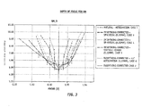
- FIG. 3 is a plot of minimum readable letter size versus defocus, for a variety of aberration corrections, for a first subject (SM).
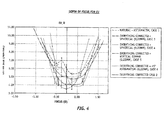
- FIG. 4 is a plot of defocus versus minimum readable letter size, for a variety of aberration corrections, for a second subject (EV)
- FIG. 5 is a plot of defocus versus minimum readable letter size, for a variety of aberration corrections, for a third subject (HW).
- case 1 is based on the naturally occurring higher-order aberrations of the subject with only lower-order astigmatism and defocus corrected; case 2 is based on a correction of all aberrations (e.g., no wavefront aberrations); case 3 is based on a correction of all aberrations except for a positive spherical aberration (e.g.
- case 4 is based on a correction of all aberrations except for a negative spherical aberration (e.g., -0.22 ⁇ m)); case 5 is based on a correction of all aberrations except for a coma aberration ((e.g., 0.22 ⁇ m)); and, case 6 is based on a correction of all aberrations except for an astigmatism aberration (e.g., 0.22 ⁇ m).
- coma e.g., case 5
- astigmatism aberration e.g., 0.22 ⁇ m
- FIG. 6 is a plot of depth of focus versus the variety of aberrations corrections shown in FIGS. 3-5 , for each of the subjects.
- FIG. 7 is a graph of the depth of focus versus the variety of aberration corrections shown in FIGS. 3-5 illustrating the average focus depth for each of the variety of aberration corrections.
- FIG. 8 is a graph of the minimum readable letter size (e.g., in the best-focus position) versus the variety of aberration corrections shown in FIGS. 3-5 illustrating the minimum letter size for each of the variety of aberration corrections.
- FIGS. 3-5 illustrate examples of induced aberrations that increase the depth of focus, while maintaining the in-focus acuity, in-focus acuity is explicitly shown in FIG. 8 .
- the cases 1 and 5 in FIG. 8 show the same in-focus acuity (letter size), while the depth of focus of these cases differ (such as shown in FIG. 7 ).
- cases 5 and 6 in FIG. 8 show the same in-focus acuity (letter size), while the depth of focus of these cases differ ( FIG. 7 ).
- cases 2 and 3 in FIG. 8 show the same in-focus acuity (e.g., based on letter size), while the depth of focus of these cases differ (as shown in FIG. 7 ). This demonstrates that by adding aberrations and/or changing the aberrations in the eye, the depth of focus of the eye can be increased, without changing the in-focus acuity.
- FIG. 9 is a Modulation Transfer Function (MTF) illustrating an MTF volume in one embodiment.
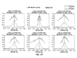
- FIG. 10 illustrates comparisons of inverse letter size versus defocus for various aberration correction types of the first subject to Modulation Transfer Function volume versus defocus for the respective aberration correction types of the first subject.
- MTF Modulation Transfer Function
- inverse letter size versus defocus for the first aberration correction type of the first subject is compared to Modulation Transfer Function volume versus defocus for the first aberration correction type of the first subject
- inverse letter size versus defocus for the second aberration correction type of the first subject is compared to Modulation Transfer Function volume versus defocus for the second aberration correction type of the first subject
- inverse letter size versus defocus for the third aberration correction type of the first subject is compared to Modulation Transfer Function volume versus defocus for the third aberration correction type of the first subject
- inverse letter size versus defocus for the fourth aberration correction type of the first subject is compared to Modulation Transfer Function volume versus defocus for the fourth aberration correction type of the first subject
- inverse letter size versus defocus for the fifth aberration correction type of the first subject is compared to Modulation Transfer Function volume versus defocus for the fifth aberration correction type of the first subject
- inverse letter size versus defocus for the sixth aberration correction type of the first subject is compared to Modulation Transfer Function volume
- FIG. 11 illustrates comparisons of inverse letter size versus defocus for various aberration correction types of the first subject to Modulation Transfer Function area versus defocus for the respective aberration correction types of the first subject.
- inverse letter size versus defocus for the first aberration correction type of the second subject is compared to Modulation Transfer Function volume versus defocus for the first aberration correction type of the second subject
- inverse letter size versus defocus for the second aberration correction type of the second subject is compared to Modulation Transfer Function volume versus defocus for the second aberration correction type of the second subject
- inverse letter size versus defocus for the third aberration correction type of the second subject is compared to Modulation Transfer Function volume versus defocus for the third aberration correction type of the second subject
- inverse letter size versus defocus for the fourth aberration correction type of the second subject is compared to Modulation Transfer Function volume versus defocus for the fourth aberration correction type of the second subject
- inverse letter size versus defocus for the fifth aberration correction type of the second subject is compared to Mod
- a depth of focus for a lens may be defined based on any number of criteria, such as a threshold of any of the MTF curves, a particular increase in spot size or wavefront error, a particular decrease in Strehl Ratio, or any other suitable criterion.
- FIG. 12 is a plot of inverse letter size versus defocus illustrating a depth of focus determination at a threshold, in one example. There are many possible definitions of depth of focus that many be used, as well as many other figures of merit that may be used for the definitions.
- any or all of the following optical metrics may be used: MTF at a particular spatial frequency, MTF volume (integrated over a particular range of spatial frequencies, either in one dimension or in two dimensions), Strehl ratio, encircled energy, RMS spot size, peak-to-valley spot size, RMS wavefront error, peak-to-valley wavefront error, and edge transition width.
- MTF at a particular spatial frequency MTF volume (integrated over a particular range of spatial frequencies, either in one dimension or in two dimensions), Strehl ratio, encircled energy, RMS spot size, peak-to-valley spot size, RMS wavefront error, peak-to-valley wavefront error, and edge transition width.
- the depth of focus may be defined as the region over which the MTF or MTF volume exceeds a threshold of 0.1.
- any suitable MTF absolute threshold may be used, such as 0.15, 0.2, 0.25, 0.3 and so forth.
- the depth of focus may be defined as the region over which the RMS spot size is less than a particular threshold value.
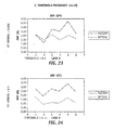
- FIG. 13 is a plot of depth of focus versus the aberration correction types determined from the psychophysical measurement and determined from theoretical calculation of MTF volume shown in FIG. 10 of the first subject.
- FIG. 14 is a plot of depth of focus versus the aberration correction types determined from the psychophysical measurement and determined from theoretical calculation of MTF volume shown in FIG. 11 of the second subject.
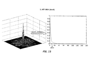
- FIG. 15 is a Modulation Transfer Function illustrating an MTF area in one embodiment.
- the radial average e.g., the averaged curvature at the center of the MTF curve
- the radial average is used to determine the MTF area.
- FIG. 16 illustrates comparisons of inverse letter size versus defocus for various aberration correction types of the first subject to Modulation Transfer Function area versus defocus for the respective aberration correction types of the first subject.
- inverse letter size versus defocus for the first aberration correction type of the first subject is compared to Modulation Transfer Function area versus defocus for the first aberration correction type of the first subject
- inverse letter size versus defocus for the second aberration correction type of the first subject is compared to Modulation Transfer Function area versus defocus for the second aberration correction type of the first subject
- inverse letter size versus defocus for the third aberration correction type of the first subject is compared to Modulation Transfer Function area versus defocus for the third aberration correction type of the first subject
- inverse letter size versus defocus for the fourth aberration correction type of the first subject is compared to Modulation Transfer Function area versus defocus for the fourth aberration correction type of the first subject
- inverse letter size versus defocus for the fifth aberration correction type of the first subject is compared to Mod
- FIG. 17 illustrates comparisons of inverse letter size versus defocus for various aberration correction types of the second subject to Modulation Transfer Function area versus defocus for the respective aberration correction types of the second subject.
- inverse letter size versus defocus for the first aberration correction type of the second subject is compared to Modulation Transfer Function area versus defocus for the first aberration correction type of the second subject
- inverse letter size versus defocus for the second aberration correction type of the second subject is compared to Modulation Transfer Function area versus defocus for the second aberration correction type of the second subject
- inverse letter size versus defocus for the third aberration correction type of the second subject is compared to Modulation Transfer Function area versus defocus for the third aberration correction type of the second subject
- inverse letter size versus defocus for the fourth aberration correction type of the second subject is compared to Modulation Transfer Function area versus defocus for the fourth aberration correction type of the second subject
- inverse letter size versus defocus for the fifth aberration correction type of the second subject is compared to Mod
- FIG. 18 is a plot of depth of focus versus the aberration correction types shown in FIG. 16 of the first subject and a MTF area threshold of 0.1.
- FIG. 19 is a plot of depth of focus versus the aberration correction types shown in FIG. 17 of the second subject and a MTF area threshold of 0.2.
- FIG, 20 is a Modulation Transfer Function illustrating a threshold frequency in one embodiment.
- the radial average is used to determine the threshold frequency from a threshold MT.
- FIG. 21 illustrates comparisons of inverse letter size versus defocus for various aberration correction types of the first subject to threshold frequency versus defocus for the respective aberration correction types of the first subject.
- inverse letter size versus defocus for the first aberration correction type of the first subject is compared to threshold frequency versus defocus for the first aberration correction type of the first subject
- inverse letter size versus defocus for the second aberration correction type of the first subject is compared to threshold frequency versus defocus for the second aberration correction type of the first subject
- inverse letter size versus defocus for the third aberration correction type of the first subject is compared to threshold frequency versus defocus for the third aberration correction type of the first subject
- inverse letter size versus defocus for the fourth aberration correction type of the first subject is compared to threshold frequency versus defocus for the fourth aberration correction type of the first subject
- inverse letter size versus defocus for the fifth aberration correction type of the first subject is compared to threshold frequency versus defocus for the fifth aberration correction type of the first
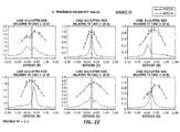
- FIG. 22 illustrates comparisons of inverse letter size versus defocus for various aberration correction types of the second subject to threshold frequency versus defocus for the respective aberration correction types of the second subject.
- inverse letter size versus defocus for the first aberration correction type of the second subject is compared to threshold frequency versus defocus for the first aberration correction type of the second subject
- inverse letter size versus defocus for the second aberration correction type of the second subject is compared to threshold frequency versus defocus for the second aberration correction type of the second subject
- inverse letter size versus defocus for the third aberration correction type of the second subject is compared to threshold frequency versus defocus for the third aberration correction type of the second subject
- inverse letter size versus defocus for the fourth aberration correction type of the second subject is compared to threshold frequency versus defocus for the fourth aberration correction type of the second subject
- inverse letter size versus defocus for the fifth aberration correction type of the second subject is compared to threshold frequency versus defocus for the fifth aberration correction type of the second
- FIG. 23 is a plot of depth of focus versus the aberration correction types determined from the psychophysical measurement and determined from theoretical calculation of the threshold frequency as shown in FIG. 21 of the first subject.
- FIG. 24 is a plot of depth of focus versus the aberration correction types determined from the pschophysical measurement and determined from theoretical calculation of the threshold frequency as shown in FIG. 22 of the second subject.
- FIG. 25 is a Modulation Transfer Function illustrating a method for determining a Modulation Transfer threshold that is determined from MT values calculated for the 10' letter size (termed ⁇ x) in one embodiment.
- FIG. 26 is a plot of depth of focus versus the aberration correction types determined from the pschophysical measurement and determined from theoretical calculation of ⁇ x of the first subject.
- FiG. 27 is a plot of depth of focus versus the aberration correction types shown determined from the pschophysical measurement and determined from theoretical calculation of ⁇ x of the second subject.
- FIG. 28 is a Modulation Transfer Function illustrating an MTF volume within a frequency range in one embodiment.
- FiG. 29 illustrates comparisons of inverse letter size versus defocus for various aberration correction types of the first subject to MTF volume within a frequency range versus defocus for the respective aberration correction types of the first subject.
- inverse letter size versus defocus for the first aberration correction type of the first subject is compared to MTF volume within a frequency range versus defocus for the first aberration correction type of the first subject
- inverse letter size versus defocus for the second aberration correction type of the first subject is compared to MTF volume within a frequency range versus defocus for the second aberration correction type of the first subject
- inverse letter size versus defocus for the third aberration correction type of the first subject is compared to MTF volume within a frequency range versus defocus for the third aberration correction type of the first subject
- inverse letter size versus defocus for the fourth aberration correction type of the first subject is compared to MTF volume within a frequency range versus defocus for the fourth aberration correction type of the first subject
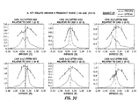
- FIG. 30 illustrates comparisons of inverse letter size versus defocus for various aberration correction types of the second subject to MTF volume within a frequency range versus defocus for the respective aberration correction types of the second subject.
- inverse letter size versus defocus for the first aberration correction type of the second subject is compared to MTF volume within a frequency range versus defocus for the first aberration correction type of the second subject
- inverse letter size versus defocus for the second aberration correction type of the second subject is compared to MTF volume within a frequency range versus defocus for the second aberration correction type of the second subject
- inverse letter size versus defocus for the third aberration correction type of the second subject is compared to MTF volume within a frequency range versus defocus for the third aberration correction type of the second subject
- inverse letter size versus defocus for the fourth aberration correction type of the second subject is compared to MTF volume within a frequency range versus defocus for the fourth aberration correction type of the second subject
- FIG. 31 is a plot of depth of focus versus the aberration correction types determined from the psychophysical measurement and determined from theoretical calculation of MTF volume within a frequency range shown in FIG. 29 of the first subject.
- FIG. 32 is a plot of depth of focus versus the aberration correction types determined from the psychophysical measurement and determined from theoretical calculation of MTF volume within a frequency range shown in FIG. 30 of the second subject.
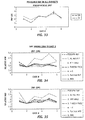
- FIG. 33 is a plot of measured depth of focus versus the aberration correction types for the first and second subjects.
- FIG. 34 is a plot comparing depth of focus measured pschophysically to depth of focus calculated with all theoretical methods versus the aberration correction types for the first subject.
- FIG. 35 is a plot comparing depth of focus measured pschophysically to depth of focus calculated with all theoretical methods versus the aberration correction types for the second subject.
- ophthalmic devices and designs may additionally be incorporated to extend the depth of focus of monofocal, multifocal, or even accommodating intraocular lenses.
- Such ophthalmic devices and designs include, but are not limited to, those disclosed in U.S. Patent Nos. 6, 126, 286 (Portney ) and 6,923,539 (Simpson et al. ), and U.S. Patent Application Number 20060116763A1 (Simpson ), all of which are herein incorporated by reference in their entirety.
- the surface profile may initially have something similar to those taught in U.S. Pat. Nos. 6,126,286 or 6,923,539 , or U.S. Pub. No. 20060116763A1 . This may be used in combination with the introduction of asymmetric aberration to provide both an extended depth of focus and a predetermined visual acuity performance.
- an extended or expanded depth of focus is provided by an ophthalmic lens or optic comprising a phase-affecting, non-diffractive mask to increase the depth of focus of an ophthalmic lens.
- the ophthalmic lens may include one or more spatially low frequency phase transitions, for example, as disclosed in U.S. Patent No. 7,061,693 , which is herein incorporated by reference in its entirety.
- Such a non-diffractive mask may be used in combination with at least one of the surfaces 2, 3, either on the same or an opposite surface to provide an optic that provides an extended depth of focus with a predetermined optical performance or visual acuity characteristic.
- Analysis and storage of the wavefront characteristics of the eye as well as the evaluation, determination, and implementation of asymmetric aberration inducement may be maintained by a control system including computer hardware and/or software, often including one or more programmable processing units operable to execute machine readable program instructions or code for implementing some or all of one or more of the methods described herein.
- the code is often embodied in a tangible media such as a memory (optionally a read only memory, a random access memory, a non-volatile memory, or the like) and/or a recording media (such as a floppy disk, a hard drive, a CD, a DVD, a memory stick, or the like).
- the code and/or associated data and signals may also be transmitted to or from the control system via a network connection (such as a wireless network, an Ethernet, an internet, an intranet, or the like) to the system, and some or all of the code may also be transmitted between components of the system and/or within the system via one or more bus, and appropriate standard or proprietary communications cards, connectors, cables, and the like will often be included in the system.
- the system is often configured to perform the calculations and signal transmission steps described herein at least in part by programming with the software code, which may be written as a single program, a series of separate subroutines or related programs, or the like.
- Standard or proprietary digital and/or analog signal processing hardware, software, and/or firmware may be utilized, and will typically have sufficient processing power to perform the calculations described herein during treatment of the patient.
- the system optionally includes a personal computer, a notebook computer, a tablet computer, a proprietary processing unit, or a combination thereof.
- Standard or proprietary input devices such as a mouse, keyboard, touchscreen, joystick, etc.
- output devices such as a printer, speakers, display, etc.
- processors having a plurality of processing units (or even separate computers) may be employed in a wide range of centralized or distributed data processing architectures.
Abstract
Description
- This Application claims the benefit of
U.S. Provisional Application No. 60/029,284, filed February 15, 2008 . - The present invention relates generally to ophthalmic lenses and more specifically to intraocular lenses having an extended depth of focus.
- Intraocular lenses (IOLs) are commonly used to replace the natural lens of the eye under cataract conditions. Alternatively, the natural tens may be replaced to correct other visual conditions, for example, to provide accommodation or pseudo-accommodation in the event a subject develops presbyopia and has diminished focusing capability on both distant objects and near objects. "Accommodation" is the ability of the eye to change focus from near to far, far to near, and all distances in between. As presbyopia progresses, accommodation ability generally decreases. For example, with presbyopia, which usually begins at around
age 40, the lens becomes less flexible. As the ciliary muscle contracts to move the lens forward, the lens typically resists due to presbyopia. Accommodating and/or multifocal intraocular lenses may be used to restore at least some degree of accommodative or pseudo-accommodative ability. - Accommodating intraocular lenses (AIOLs) are general configured to focus on objects over a range of distances typically by moving axially and/or by changing shape in response to an ocular force produced by the ciliary muscle, zonules, and/or capsular bag of the eye. Current accommodating intraocular lenses are capable of providing about 0.5 diopter of objective accommodation. Multifocal intraocular lenses (MFIOLs) provide a pseudo-accommodation by simultaneously providing two or more foci, for example, one to provide distant vision and the other to provide near vision. This pseudo-accommodation may have some trade-off, such as dysphotopsia (e.g., halos or glare), reduced contrast sensitivity due to the continual presence of defocused light, reduced intermediate vision, pupil dependent performance, or the like. Over time, patients with multifocal intraocular lenses generality select the focus that provides the sharper image and ignore other biurred images.
- Another approach to providing some degree of simulated accommodation is by extending the depth of focus of a traditional monofocal lens so that objects over a broader range of distances are simultaneously resolved. This approach also has some trade-off with reduced contrast sensitivity. Examples of this approach are discussed in
U.S. Pat. Nos. 6,126,286 ,6,923,539 , and7,061,692 . - An intraocular lens is needed that extends the depth of focus of an eye while minimizing the occurrence of one or more factors reducing the optical performance of the eye, such as dysphotopsia, reduced contrast sensitivity, reduced intermediate vision, pupil dependent performance, or the like. More particularly, an intraocular lens is needed that extends the depth of focus of an eye without significantly reducing the in-focus visual acuity of the eye and while minimizing the occurrence of one or more factors reducing the optical performance of the eye, such as dysphotopsia, reduced contract sensitivity, reduced intermediate vision, pupil dependent performance, or the like. Further, systems and methods for extending the depth of focus of the eye while minimizing the occurrence of one or more factors reducing the optical performance of the eye are needed.
- The present invention is generally directed to ophthalmic devices, systems, and methods for extending the depth of focus of a subject's vision by introducing at least some higher order asymmetric aberration in the eye. The ophthalmic device may be an intraocular lens, a contact lens, a corneal inlay or inlay, a pair of spectacles, or the like. In some embodiments, the ophthalmic device may be a part of the structure of the natural eye, for example, the resulting corneal surface following a refractive procedure, such as a LASIK or PRK procedure. Embodiments of the present invention may find particular use in ophthalmic devices having a multifocal element (e.g., a diffractive or refractive lens producing two or more foci or images) or having accommodative capabilities.
- In one aspect of the present invention, a lens for ophthalmic use, such as an intraocular lens, is provided. The lens includes an optic having a clear aperture disposed about a central axis. The optic includes a first surface and an opposing second surface. The first and second surfaces are together configured to introduce at least some asymmetric aberration in the eye to increase the depth of focus while maintaining the in-focus visual acuity of the eye. Maintaining in-focus visual acuity is referred to herein as having essentially the same letter acuity or reading acuity and/or having an identical functional acuity, which is regarded as normal for a particular age group, and which does not limit the functional vision. Maintaining in-focus visual acuity specifically excludes super-acuity, that is, acuity that significantly exceeds the acuity associated with normal 20/20 vision. In one embodiment, the ophthalmic lens introduces some degree of coma, or other higher order asymmetric aberration, in the eye while maintaining in-focus visual acuity of the eye.
- In another embodiment, a lens system for an eye is provided, and the lens system includes a first lens having a first optical axis and a second lens adjacent the first lens. The second lens has a second optical axis being non-signed with the first optical axis. The first lens and second lens are together configured to introduce at least some asymmetric aberration to the eye to extend the depth of focus while maintaining the in-focus visual acuity of the eye.
- In another embodiment, a method is provided for modifying a depth of focus of an eye. The method includes measuring a wavefront aberration of the eye, determining an in-focus visual acuity of the eye, and determining an asymmetric aberration to be induced in the wavefront aberration of the eye. The depth of focus is extended by the asymmetric aberration when induced in the wavefront aberration and white maintaining the in-focus visual acuity.
- in other embodiments, the present invention may be used in concert with a multifocal intraocular lens to extend all of the focal points thereof, with an accommodating intraocular lens to extend the functional range of vision available to the patient, with other extended depth of focus techniques, with targeted correction of other higher-order aberrations, with chromatic aberration correction, and the like,
- Embodiments of the present invention may be better understood from the following detailed description when read in conjunction with the accompanying drawings. Such embodiments, which are for illustrative purposes only, depict the novel and non-obvious aspects of the invention, The drawings include the following figures, with like numerals indicating like parts:
-
FIG. 1 is a schematic drawing of a human eye after implantation with an intraocular lens; -
FIG. 2 is a schematic drawing of a thin lens model that approximates the human eye ofFIG. 1 ; -
FIG. 3 is a plot of defocus versus minimum readable letter size, for a variety of aberration corrections, for a first subject; -
FIG. 4 is a plot of defocus versus minimum readable better size, for a variety of aberration corrections, for a second subject; -
FiG. 5 is a plot of defocus versus minimum readable letter size, for a variety of aberration corrections, for a third subject; -
FIG. 6 is a plot of depth of focus versus the variety of aberration corrections shown inFiGS. 3-5 , for each of the subjects; -
FIG. 7 is a graph of the depth of focus versus the variety of aberration corrections shown inFIGS. 3-5 illustrating the average focus depth for each of the variety of aberration corrections; -
FIG. 8 is a graph of the minimum readable letter size versus the variety of aberration corrections shown inFIGS. 3-5 illustrating the minimum readable letter size for each of the variety of aberration corrections; -
FIG. 9 is a Modulation Transfer Function (MTF) illustrating an MTF volume in one embodiment; -
FIG. 10 illustrates comparisons of inverse letter size versus defocus for various aberration correction types of the first subject to Modulation Transfer Function volume versus defocus for the respective aberration correction types of the first subject; -
FiG. 11 illustrates comparisons of inverse letter size versus defocus for various aberration correction types of the second subject to Modulation Transfer Function volume versus defocus for the respective aberration correction types of the second subject: -
FIG. 12 illustrates comparisons is a plot of inverse Letter size versus defocus illustrating depth of focus determination at a threshold in one example; -
FIG. 13 is a plot of depth of focus versus the aberration correction types determined from the psychophysical measurement and determined from theoretical calculation of MTF volume shown inFIG. 10 of the first subject; -
FIG. 14 is a plot of depth of focus versus the aberration correction types determined from the psychophysical measurement and determined from theoretical calculation of MTF volume shown inFIG. 11 of the second subject; -
FIG. 15 is a Modulation Transfer Function illustrating an MTF area in one embodiment; -
FIG. 16 illustrates comparisons of inverse letter size versus defocus for various aberration correction types of the first subject to Modulation Transfer Function area versus defocus for the respective aberration correction types of the first subject; -
FIG. 17 illustrates comparisons of inverse letter size versus defocus for various aberration correction types of the second subject to Modulation Transfer Function area versus defocus for the respective aberration correction types of the second subject; -
FIG. 18 is a plot of depth of focus versus the aberration correction types shown inFIG. 16 of the first subject and a MTF area threshold of 0,1: -
FIG. 19 is a plot of depth of focus versus the aberration correction types shown inFIG. 17 of the second subject and a MTF area threshold of 0.2: -
FIG. 20 is a Modulation Transfer Function illustrating a threshold frequency in one embodiment; -
FIG. 21 illustrates comparisons of inverse letter size versus defocus for various aberration correction types of the first subject to threshold frequency versus defocus for the respective aberration correction types of the first subject; -
FIG. 22 illustrates comparisons of inverse letter size versus defocus for various aberration correction types of the second subject to threshold frequency versus defocus for the respective aberration correction types of the second subject; -
FIG. 23 is a plot of depth of focus versus the aberration correction types determined from the pschophysical measurement and determined from theoretical calculation of the threshold frequency as shown inFIG. 21 of the first subject; -
FIG. 24 is a plot of depth of focus versus the aberration correction types determined from the psychophysical measurement and determined from theoretical calculation of the threshold frequency as shown inFIG. 22 of the second subject; -
FIG. 26 is a Modulation Transfer Function illustrating a method for determining a Modulation Transfer threshold that is determined from MT values calculated for the 10' letter size (termed ±x) in one embodiment. -
FIG. 26 is a plot of depth of focus versus the aberration correction types determined from the pschophysical measurement and determined from theoretical calculation of ±x of the first subject; -
FIG. 27 is a plot of depth of focus versus the aberration correction types shown determined from the pschophysica measurement and determined from theoretical calculation of ±x of the second subject; -
FIG. 28 is a Modulation Transfer Function illustrating an MTF volume within a frequency range in one embodiment; -
FIG. 29 illustrates comparisons of inverse letter size versus defocus for various aberration correction types of the first subject to MTF volume within a frequency range versus defocus for the respective aberration correction types of the first subject; -
FIG. 30 illustrates comparisons of inverse letter size versus defocus for various aberration correction types of the second subject to MTF volume within a frequency range versus defocus for the respective aberration correction types of the second subject; -
FIG. 31 is a plot of depth of focus versus the aberration correction types determined from the psychophysical measurement and determined from theoretical calculation of MTF volume within a frequency range shown inFIG. 29 of the first subject; -
FIG. 32 is a plot of depth of focus versus the aberration correction types determined from the pschophysical measurement and determined from theoretical calculation of MTF volume within a frequency range shown inFIG. 30 of the second subject; -
FIG. 33 is a plot of measured depth of focus versus the aberration correction types for the first and second subjects; -
FIG. 34 is a plot comparing depth of focus measured pschophysically to depth of focus calculated with all theoretical methods versus the aberration correction types for the first subject; and -
FIG. 35 is a plot comparing depth of focus measured pschophysically to depth of focus calculated with all theoretical methods versus the aberration correction types for the second subject. - An ophthalmic lens, an ophthalmic system, and a method of modifying optical characteristics of an eye are provided in accordance with the present invention. In general, at least some asymmetric aberration is introduced in the eye to increase the depth of focus of the eye while maintaining in-focus visual acuity. Maintaining in-focus visual acuity is referred to herein as having essentially the same letter acuity or reading acuity or having an identical functional acuity, which is regarded as normal for a particular age group, and which does not limit the functional vision. Maintaining in-focus visual acuity specifically excludes super-acuity, that is, acuity that significantly exceeds the acuity associated with formal 20/20 vision.
- In one embodiment, the ophthalmic lens introduces a higher order asymmetric aberration (e.g., some degree of coma or the like) in the eye while maintaining the in-focus visual acuity of the eye. Due to the near-spherical or substantially spherical geometry of the anterior surface of the cornea, two types of aberrations, spherical aberration and coma, may occur. The term "coma" is referred to herein as an optical aberration in which the image of a point source is generally a comet-shaped figure. Spherical aberration and coma are similar to one another by inadequately imaging or focusing rays at the same point. Coma differs from spherical aberration, however, in that a point object is imaged not as a circle but as a comet-shaped figure. Nevertheless, both cases are characterized by a loss of definition at the focal spot. By inducing an asymmetric aberration (e.g., coma or other higher order asymmetric aberration) to the wavefront aberration of a pseudophakic eye, the depth of focus may be increased.
- In one embodiment, an ophthalmic lens with pre-determined bending factors (e.g., to produce asymmetric aberrations) introduces asymmetric aberration in the eye while maintaining in-focus visual acuity. For example, the ophthalmic lens may be formed with an asymmetric curvature on the anterior side of the corresponding optic, the posterior side of the corresponding optic, or a combination of the anterior and posterior side of the optic. In another embodiment, an ophthalmic lens may be lathe-cut (e.g., the surface of the lens may be lathed) to be rotationally asymmetric. In another embodiment, an ophthalmic lens may be molded to be rotationally asymmetric. For example,
U.S. Pat. No. 5,620,720 , the entire disclosure of which is incorporated herein, discloses a cast molding technique for forming intraocular lenses. - In another embodiment, the lens may be mechanically configured to be tilted or de-centered in the eye (e.g., by a controlled and pre-determined degree). For example,
U.S. Pat. Nos. 5,567,365 and5,571,177 andU.S. Pat. Application No. 12/239,462 filed September 26, 2008, to Deacon et al - In another embodiment, an Alvarez lens can be used and positioned to introduce a pre-determined degree of asymmetric aberration. For example,
U.S. Pat. No. 3,305,294 discloses an Alvarez lens with lens elements that are movable relative to each other transversely to the optical axis of the lens andPCT Pub. No. WO/2006/025726 discloses an Alvarez-type intraocular lens, both of which are incorporated in entirety herein. In another embodiment, a dual lens system (e.g., axially positioned with respect to one another) that is de-centered with respect to one another may be used. - Other higher order asymmetrical aberrations may be used to extend or increase the depth of focus including, but not necessarily limited to, astigmatism, high-order astigmatism, vertical coma, lateral coma, trefoil, and the line, and combinations thereof may also be used. Examples of ophthalmic lenses include, but are not necessarily limited to, intraocular lenses, external lenses, contact lenses, intrastromal lens implants, implantable shaped corneal tissue, and the like.
- Because each individual vision typically has a unique wavefront characteristic, the ophthalmic lens may similarly have a variety of configurations to introduce the asymmetric aberration while maintaining in-focus visual acuity. Detailed information about the wavefront characteristics associated with the eye (e.g., optical aberrations) may be acquired. Examples of such detailed information include, but are not necessarily limited to, the extent of a desired refractive correction, the location in the eye associated with the correction (e.g., where the correction can be made most effectively), and the like. Wavefront analysis techniques, made possible by devices such as a Hartmann-Shack type sensor, can be used to generate maps of refractive power. Other wavefront analysis techniques and sensors may also be used. The maps of refractive power, or similar refractive power information provided by other means, such as corneal topographs or the like, can then be used to identify and locate the optical aberrations that require correction.
- The ophthalmic lens may also have multifocal characteristics. With a multifocal lens embodiment, the introduced asymmetric aberration preferably extends the depth of focus associated with all of the focal points of the multifocal lens. In other embodiments, the introduced asymmetric aberration can extend the depth of focus in either the near or the far focus position. In an accommodating lens embodiment, the lens with asymmetric aberration extends the functional range of vision available to the patient. Furthermore, the introduction of a pre-determined degree of asymmetric aberration (e.g., while maintaining in-focus visual acuity) can be combined with other extended depth of focus concepts, such as binary phase masks, Senses that utilize hyperfocality, zonal aspheric lenses, low-add multifocal lenses, and the like, with targeted correction of other higher-order aberrations, such as spherical aberration and/or astigmatism (e.g., using a toric lens), and/or with chromatic aberration correction (e.g., using a diffractive monofocal lens).
- Referring to the drawings, a
human eye 10 is shown inFIG. 1 after anintraocular lens 1 has been inserted. Ought enters (e.g., from the left ofFIG. 1 ) and passes through acornea 14, ananterior chamber 15, aniris 16, and enters acapsular bag 17. Prior to insertion, the natural lens (not shown) occupies essentially the entire interior of thecapsular bag 17, After insertion, thecapsular bag 17 may house theintraocular lens 1, in addition to a fluid that occupies the remaining volume and equalizes the pressure in theeye 10. Theintraocular lens 1 is preferably constructed to introduce an asymmetric aberration in theeye 10 without significantly reducing the in-focus visual acuity thereof. After passing through theintraocular lens 1, light exits aposterior wall 18 of thecapsular bag 17, passes through aposterior chamber 11, and strikes theretina 12, which detects the light and converts it to a signal transmitted through the optic nerve to the brain. - The
intraocular lens 1 has an optic 1 a with a refractive index greater than the surrounding fluid. The optic 1a has ananterior su rface 2 facing away from theretina 12 and aposterior surface 3 facing toward theretina 12. In this embodiment, theanterior surface 2 andposterior surface 3 are shaped to induce a predetermined amount of coma in theeye 10. In one embodiment, theanterior surface 2 is rotationally asymmetric with respect to theposterior surface 3. The optic 1a is held in place by a haptic 19, which couples the optic 1a to thecapsular bag 17 after insertion. In the illustrated embodiment, the optic 1a is suspended within thecapsular bag 17, for example, to allow accommodative movement of the optic 1a a of theintraocular lens 1 along the optical axis, such as may be found with accommodative intraocular lenses. Alternatively, theintraocular lens 1 may be disposed adjacent to, and even biased against, theposterior wall 18, for example, to reduce cellular growth on the optic 1a. The optic 1a may be either a monofocal intraocular lens or a multifocal intraocular lens. - A well-corrected eye typically forms an image at the
retina 12. If thelens 1 has too much or too little power, the image shifts axially among the optical axis away from theretina 12, toward or away from the lens, The power required to focus on a close or near object is generally greater than the power required to focus on a distant or far object. The difference in optical power between the farthest and nearest object that may be brought into focus by a particular lens or lens system is typically referred to as an "add power" (e.g., in the case of a multifocal intraocular lens) or a "range of accommodation" or "accommodative range" (e.g., in the case of an accommodating intraocular lens that responds to ciliary muse contraction to move axially and/or deform so as to change the optical power of the optic). A normal range of add power or accommodation is generally about 4 Diopters at the plane of the optic 1a, although this number may be as low as 3 or fewer Diopters or as high as 6 or more Diopters based on the geometry of the eye. - In many cases, the optical system of the eye may be well approximated by a thin lens model, shown schematically in
FIG. 2 . Such athin lens system 20 may be used to predict the location of an image for a given object distance, Z. In addition, thethin lens system 20 may also be used to predict the power required of a lens to bring objects at the object distance, Z, into focus on the retina. This may be used to predict or determine in-focus visual acuity for a particular optical system or eye. - A
marginal light ray 29 originates at the base of anobject 21. where theray 29 crosses anoptical axis 28. Theray 29 passes through anoptional spectacle 22 having a power, φspectacle, and enters the eye. The eye itself is represented by acornea 23 with a power, φcornea, an aperture stop (or pupil) 24, anintraocular lens 25 with a power, φlens, and aretina 26. Animage 27 is formed of theobject 21 at the location where themarginal ray 29 intersects theoptical axis 28. If theobject 21 is "in focus," then theimage 27 is formed at theretina 26. If the object is "out of focus," then the image is translated axially away from theretina 26, being either too close to the lens or too far from the lens. The space between theobject 21 and thecornea 23 is assumed to be filled with air, having a refractive index of nair (e.g., typically 1). The space between thecornea 23 and theretina 26 is assumed to be filled with a fluid having a refractive index of neye. - One exemplary figure of merit for tracking the performance of visual systems is known as a Modulation Transfer Function (MTF). The MTF generally indicates the ability of an optical system to reproduce (e.g., transfer) various levels of detail (e.g., spatial frequencies) from the object to the image. MTF is particularity desirable as a figure of merit because it may be both predicted by simulation and approximately measured through the visual response of real patients.
- The MTF is related to the apparent contrast of alternating bright and dark bars of an image. If the MTF is 1, then the bright areas generally appear completely bright, and the dark areas generally appear completely dark. If the MTF is 0, both areas appear as gray, with generally little to no distinction between bright and dark areas. Typical MTF values lie between 0 and 1 with some light bleeding into the dark areas and some darkness bleeding into the light areas.
- The MTF has a dependence on spatial frequency, which is inversely related to the width of the alternating bright and dark bars in the image. Note that MTF is particularly suited for human vision testing, in that the spatial frequency may be controlled during a test by controlling the size of a letter "E," where the widths of the prongs in the "E" have a prescribed size. MTF is measured along two orthogonal axes (e.g., an x-axis and a y-axis or a horizontal axis and a vertical axis).
- Spatial frequency is typically reported in units of line pairs per mm at the retina. At low spatial frequencies (e.g., represented with wider bars), the MTF is generally higher than at high spatial frequencies (e.g., represented with narrower bars). For frequencies greater than a predetermined cutoff spatial frequency, the MTF- is 0. This is a property governed by the physics of diffraction. MTF may be calculated in a straightforward numerical manner, either by a ray-tracing program such as Oslo or Zemax, by another existing simulation tool, or by self-written code, all of which provide generally equivalent results with varying degrees of sophistication,
-
FIG. 3 is a plot of minimum readable letter size versus defocus, for a variety of aberration corrections, for a first subject (SM).FIG. 4 is a plot of defocus versus minimum readable letter size, for a variety of aberration corrections, for a second subject (EV),FIG. 5 is a plot of defocus versus minimum readable letter size, for a variety of aberration corrections, for a third subject (HW). Six cases were used forcomparisons case 1 is based on the naturally occurring higher-order aberrations of the subject with only lower-order astigmatism and defocus corrected;case 2 is based on a correction of all aberrations (e.g., no wavefront aberrations);case 3 is based on a correction of all aberrations except for a positive spherical aberration (e.g. 0.22 µm);case 4 is based on a correction of all aberrations except for a negative spherical aberration (e.g., -0.22 µm));case 5 is based on a correction of all aberrations except for a coma aberration ((e.g., 0.22 µm)); and,case 6 is based on a correction of all aberrations except for an astigmatism aberration (e.g., 0.22 µm). As best shown inFIGS. 3-5 , the introduction of coma (e.g., case 5) provided the greatest depth of focus for all three subjects. -
FIG. 6 is a plot of depth of focus versus the variety of aberrations corrections shown inFIGS. 3-5 , for each of the subjects.FIG. 7 is a graph of the depth of focus versus the variety of aberration corrections shown inFIGS. 3-5 illustrating the average focus depth for each of the variety of aberration corrections.FIG. 8 is a graph of the minimum readable letter size (e.g., in the best-focus position) versus the variety of aberration corrections shown inFIGS. 3-5 illustrating the minimum letter size for each of the variety of aberration corrections. -
FIGS. 3-5 illustrate examples of induced aberrations that increase the depth of focus, while maintaining the in-focus acuity, in-focus acuity is explicitly shown inFIG. 8 . For example, thecases FIG. 8 show the same in-focus acuity (letter size), while the depth of focus of these cases differ (such as shown inFIG. 7 ). Similarly,cases FIG. 8 show the same in-focus acuity (letter size), while the depth of focus of these cases differ (FIG. 7 ). As a third example,cases FIG. 8 show the same in-focus acuity (e.g., based on letter size), while the depth of focus of these cases differ (as shown inFIG. 7 ). This demonstrates that by adding aberrations and/or changing the aberrations in the eye, the depth of focus of the eye can be increased, without changing the in-focus acuity. -
FIG. 9 is a Modulation Transfer Function (MTF) illustrating an MTF volume in one embodiment.FIG. 10 illustrates comparisons of inverse letter size versus defocus for various aberration correction types of the first subject to Modulation Transfer Function volume versus defocus for the respective aberration correction types of the first subject. For example, inverse letter size versus defocus for the first aberration correction type of the first subject is compared to Modulation Transfer Function volume versus defocus for the first aberration correction type of the first subject, inverse letter size versus defocus for the second aberration correction type of the first subject is compared to Modulation Transfer Function volume versus defocus for the second aberration correction type of the first subject, inverse letter size versus defocus for the third aberration correction type of the first subject is compared to Modulation Transfer Function volume versus defocus for the third aberration correction type of the first subject, inverse letter size versus defocus for the fourth aberration correction type of the first subject is compared to Modulation Transfer Function volume versus defocus for the fourth aberration correction type of the first subject, inverse letter size versus defocus for the fifth aberration correction type of the first subject is compared to Modulation Transfer Function volume versus defocus for the fifth aberration correction type of the first subject, and inverse letter size versus defocus for the sixth aberration correction type of the first subject is compared to Modulation Transfer Function volume versus defocus for the sixth aberration correction type of the first subject. The peak of the MTF curves is at zero defocus. In each of the comparisons, a psychophysical measurement (e.g., "psicoph") is compared with a theoretical calculation (e.g., "optical"). -
FIG. 11 illustrates comparisons of inverse letter size versus defocus for various aberration correction types of the first subject to Modulation Transfer Function area versus defocus for the respective aberration correction types of the first subject. For example, inverse letter size versus defocus for the first aberration correction type of the second subject is compared to Modulation Transfer Function volume versus defocus for the first aberration correction type of the second subject, inverse letter size versus defocus for the second aberration correction type of the second subject is compared to Modulation Transfer Function volume versus defocus for the second aberration correction type of the second subject, inverse letter size versus defocus for the third aberration correction type of the second subject is compared to Modulation Transfer Function volume versus defocus for the third aberration correction type of the second subject, inverse letter size versus defocus for the fourth aberration correction type of the second subject is compared to Modulation Transfer Function volume versus defocus for the fourth aberration correction type of the second subject, inverse letter size versus defocus for the fifth aberration correction type of the second subject is compared to Modulation Transfer Function volume versus defocus for the fifth aberration correction type of the second subject, and inverse letter size versus defocus for the sixth aberration correction type of the second subject is compared to Modulation Transfer Function volume versus defocus for the sixth aberration correction type of the second subject. - A depth of focus for a lens may be defined based on any number of criteria, such as a threshold of any of the MTF curves, a particular increase in spot size or wavefront error, a particular decrease in Strehl Ratio, or any other suitable criterion.
FIG. 12 is a plot of inverse letter size versus defocus illustrating a depth of focus determination at a threshold, in one example. There are many possible definitions of depth of focus that many be used, as well as many other figures of merit that may be used for the definitions. For instance, any or all of the following optical metrics may be used: MTF at a particular spatial frequency, MTF volume (integrated over a particular range of spatial frequencies, either in one dimension or in two dimensions), Strehl ratio, encircled energy, RMS spot size, peak-to-valley spot size, RMS wavefront error, peak-to-valley wavefront error, and edge transition width. Given the many possible figures of merit, there are several ways to evaluate them to define a depth of focus. - One way is to define an absolute threshold, where the crossings of the figure of merit with the threshold define the depth of focus. For instance, the depth of focus may be defined as the region over which the MTF or MTF volume exceeds a threshold of 0.1. Alternatively, any suitable MTF absolute threshold may be used, such as 0.15, 0.2, 0.25, 0.3 and so forth. Alternatively, the depth of focus may be defined as the region over which the RMS spot size is less than a particular threshold value.
-
FIG. 13 is a plot of depth of focus versus the aberration correction types determined from the psychophysical measurement and determined from theoretical calculation of MTF volume shown inFIG. 10 of the first subject.FIG. 14 is a plot of depth of focus versus the aberration correction types determined from the psychophysical measurement and determined from theoretical calculation of MTF volume shown inFIG. 11 of the second subject. -
FIG. 15 is a Modulation Transfer Function illustrating an MTF area in one embodiment. The radial average (e.g., the averaged curvature at the center of the MTF curve) is used to determine the MTF area. -
FIG. 16 illustrates comparisons of inverse letter size versus defocus for various aberration correction types of the first subject to Modulation Transfer Function area versus defocus for the respective aberration correction types of the first subject. For example, inverse letter size versus defocus for the first aberration correction type of the first subject is compared to Modulation Transfer Function area versus defocus for the first aberration correction type of the first subject, inverse letter size versus defocus for the second aberration correction type of the first subject is compared to Modulation Transfer Function area versus defocus for the second aberration correction type of the first subject, inverse letter size versus defocus for the third aberration correction type of the first subject is compared to Modulation Transfer Function area versus defocus for the third aberration correction type of the first subject inverse letter size versus defocus for the fourth aberration correction type of the first subject is compared to Modulation Transfer Function area versus defocus for the fourth aberration correction type of the first subject, inverse letter size versus defocus for the fifth aberration correction type of the first subject is compared to Modulation Transfer Function area versus defocus for the fifth aberration correction type of the first subject, and inverse letter size versus defocus for the sixth aberration correction type of the first subject is compared to Modulation Transfer Function area versus defocus for the sixth aberration correction type of the first subject. -
FIG. 17 illustrates comparisons of inverse letter size versus defocus for various aberration correction types of the second subject to Modulation Transfer Function area versus defocus for the respective aberration correction types of the second subject. For example, inverse letter size versus defocus for the first aberration correction type of the second subject is compared to Modulation Transfer Function area versus defocus for the first aberration correction type of the second subject, inverse letter size versus defocus for the second aberration correction type of the second subject is compared to Modulation Transfer Function area versus defocus for the second aberration correction type of the second subject, inverse letter size versus defocus for the third aberration correction type of the second subject is compared to Modulation Transfer Function area versus defocus for the third aberration correction type of the second subject, inverse letter size versus defocus for the fourth aberration correction type of the second subject is compared to Modulation Transfer Function area versus defocus for the fourth aberration correction type of the second subject, inverse letter size versus defocus for the fifth aberration correction type of the second subject is compared to Modulation Transfer Function area versus defocus for the fifth aberration correction type of the second subject, and inverse letter size versus defocus for the sixth aberration correction type of the second subject is compared to Modulation Transfer Function area versus defocus for the sixth aberration correction type of the second subject. -
FIG. 18 is a plot of depth of focus versus the aberration correction types shown inFIG. 16 of the first subject and a MTF area threshold of 0.1.FIG. 19 is a plot of depth of focus versus the aberration correction types shown inFIG. 17 of the second subject and a MTF area threshold of 0.2. -
FIG, 20 is a Modulation Transfer Function illustrating a threshold frequency in one embodiment. The radial average is used to determine the threshold frequency from a threshold MT. -
FIG. 21 illustrates comparisons of inverse letter size versus defocus for various aberration correction types of the first subject to threshold frequency versus defocus for the respective aberration correction types of the first subject. For example, inverse letter size versus defocus for the first aberration correction type of the first subject is compared to threshold frequency versus defocus for the first aberration correction type of the first subject, inverse letter size versus defocus for the second aberration correction type of the first subject is compared to threshold frequency versus defocus for the second aberration correction type of the first subject, inverse letter size versus defocus for the third aberration correction type of the first subject is compared to threshold frequency versus defocus for the third aberration correction type of the first subject, inverse letter size versus defocus for the fourth aberration correction type of the first subject is compared to threshold frequency versus defocus for the fourth aberration correction type of the first subject, inverse letter size versus defocus for the fifth aberration correction type of the first subject is compared to threshold frequency versus defocus for the fifth aberration correction type of the first subject, and inverse letter size versus defocus for the sixth aberration correction type of the first subject is compared to threshold frequency versus defocus for the sixth aberration correction type of the first subject. -
FIG. 22 illustrates comparisons of inverse letter size versus defocus for various aberration correction types of the second subject to threshold frequency versus defocus for the respective aberration correction types of the second subject. For example, inverse letter size versus defocus for the first aberration correction type of the second subject is compared to threshold frequency versus defocus for the first aberration correction type of the second subject, inverse letter size versus defocus for the second aberration correction type of the second subject is compared to threshold frequency versus defocus for the second aberration correction type of the second subject, inverse letter size versus defocus for the third aberration correction type of the second subject is compared to threshold frequency versus defocus for the third aberration correction type of the second subject, inverse letter size versus defocus for the fourth aberration correction type of the second subject is compared to threshold frequency versus defocus for the fourth aberration correction type of the second subject, inverse letter size versus defocus for the fifth aberration correction type of the second subject is compared to threshold frequency versus defocus for the fifth aberration correction type of the second subject, and inverse letter size versus defocus for the sixth aberration correction type of the second subject is compared to threshold frequency versus defocus for the sixth aberration correction type of the second subject. -
FIG. 23 is a plot of depth of focus versus the aberration correction types determined from the psychophysical measurement and determined from theoretical calculation of the threshold frequency as shown inFIG. 21 of the first subject.FIG. 24 is a plot of depth of focus versus the aberration correction types determined from the pschophysical measurement and determined from theoretical calculation of the threshold frequency as shown inFIG. 22 of the second subject. -
FIG. 25 is a Modulation Transfer Function illustrating a method for determining a Modulation Transfer threshold that is determined from MT values calculated for the 10' letter size (termed ±x) in one embodiment. -
FIG. 26 is a plot of depth of focus versus the aberration correction types determined from the pschophysical measurement and determined from theoretical calculation of ±x of the first subject.FiG. 27 is a plot of depth of focus versus the aberration correction types shown determined from the pschophysical measurement and determined from theoretical calculation of ±x of the second subject. -
FIG. 28 is a Modulation Transfer Function illustrating an MTF volume within a frequency range in one embodiment. -
FiG. 29 illustrates comparisons of inverse letter size versus defocus for various aberration correction types of the first subject to MTF volume within a frequency range versus defocus for the respective aberration correction types of the first subject. For example, inverse letter size versus defocus for the first aberration correction type of the first subject is compared to MTF volume within a frequency range versus defocus for the first aberration correction type of the first subject, inverse letter size versus defocus for the second aberration correction type of the first subject is compared to MTF volume within a frequency range versus defocus for the second aberration correction type of the first subject, inverse letter size versus defocus for the third aberration correction type of the first subject is compared to MTF volume within a frequency range versus defocus for the third aberration correction type of the first subject, inverse letter size versus defocus for the fourth aberration correction type of the first subject is compared to MTF volume within a frequency range versus defocus for the fourth aberration correction type of the first subject, inverse letter size versus defocus for the fifth aberration correction type of the first subject is compared to MTF volume within a frequency range versus defocus for the fifth aberration correction type of the first subject, and inverse letter size versus defocus for the sixth aberration correction type of the first subject is compared to MTF volume within a frequency range versus defocus for the sixth aberration correction type of the first subject. -
FIG. 30 illustrates comparisons of inverse letter size versus defocus for various aberration correction types of the second subject to MTF volume within a frequency range versus defocus for the respective aberration correction types of the second subject. For example, inverse letter size versus defocus for the first aberration correction type of the second subject is compared to MTF volume within a frequency range versus defocus for the first aberration correction type of the second subject, inverse letter size versus defocus for the second aberration correction type of the second subject is compared to MTF volume within a frequency range versus defocus for the second aberration correction type of the second subject, inverse letter size versus defocus for the third aberration correction type of the second subject is compared to MTF volume within a frequency range versus defocus for the third aberration correction type of the second subject, inverse letter size versus defocus for the fourth aberration correction type of the second subject is compared to MTF volume within a frequency range versus defocus for the fourth aberration correction type of the second subject, inverse letter size versus defocus for the fifth aberration correction type of the second subject is compared to MTF volume within a frequency range versus defocus for the fifth aberration correction type of the second subject, and inverse letter size versus defocus for the sixth aberration correction type of the second subject is compared to MTF volume within a frequency range versus defocus for the sixth aberration correction type of the second subject. -
FIG. 31 is a plot of depth of focus versus the aberration correction types determined from the psychophysical measurement and determined from theoretical calculation of MTF volume within a frequency range shown inFIG. 29 of the first subject.FIG. 32 is a plot of depth of focus versus the aberration correction types determined from the psychophysical measurement and determined from theoretical calculation of MTF volume within a frequency range shown inFIG. 30 of the second subject. -
FIG. 33 is a plot of measured depth of focus versus the aberration correction types for the first and second subjects. -
FIG. 34 is a plot comparing depth of focus measured pschophysically to depth of focus calculated with all theoretical methods versus the aberration correction types for the first subject.FIG. 35 is a plot comparing depth of focus measured pschophysically to depth of focus calculated with all theoretical methods versus the aberration correction types for the second subject. - In some embodiments, other ophthalmic devices and designs may additionally be incorporated to extend the depth of focus of monofocal, multifocal, or even accommodating intraocular lenses. Such ophthalmic devices and designs include, but are not limited to, those disclosed in
U.S. Patent Nos. 6, 126, 286 (Portney ) and6,923,539 (Simpson et al. ), andU.S. Patent Application Number 20060116763A1 (Simpson ), all of which are herein incorporated by reference in their entirety. In certain embodiments, the surface profile may initially have something similar to those taught inU.S. Pat. Nos. 6,126,286 or6,923,539 , orU.S. Pub. No. 20060116763A1 . This may be used in combination with the introduction of asymmetric aberration to provide both an extended depth of focus and a predetermined visual acuity performance. - In some embodiments, an extended or expanded depth of focus is provided by an ophthalmic lens or optic comprising a phase-affecting, non-diffractive mask to increase the depth of focus of an ophthalmic lens. In such embodiments, the ophthalmic lens may include one or more spatially low frequency phase transitions, for example, as disclosed in
U.S. Patent No. 7,061,693 , which is herein incorporated by reference in its entirety. Such a non-diffractive mask may be used in combination with at least one of thesurfaces - Analysis and storage of the wavefront characteristics of the eye as well as the evaluation, determination, and implementation of asymmetric aberration inducement (i.e., for extending the depth of focus) may be maintained by a control system including computer hardware and/or software, often including one or more programmable processing units operable to execute machine readable program instructions or code for implementing some or all of one or more of the methods described herein. The code is often embodied in a tangible media such as a memory (optionally a read only memory, a random access memory, a non-volatile memory, or the like) and/or a recording media (such as a floppy disk, a hard drive, a CD, a DVD, a memory stick, or the like). The code and/or associated data and signals may also be transmitted to or from the control system via a network connection (such as a wireless network, an Ethernet, an internet, an intranet, or the like) to the system, and some or all of the code may also be transmitted between components of the system and/or within the system via one or more bus, and appropriate standard or proprietary communications cards, connectors, cables, and the like will often be included in the system. The system is often configured to perform the calculations and signal transmission steps described herein at least in part by programming with the software code, which may be written as a single program, a series of separate subroutines or related programs, or the like. Standard or proprietary digital and/or analog signal processing hardware, software, and/or firmware may be utilized, and will typically have sufficient processing power to perform the calculations described herein during treatment of the patient. The system optionally includes a personal computer, a notebook computer, a tablet computer, a proprietary processing unit, or a combination thereof. Standard or proprietary input devices (such as a mouse, keyboard, touchscreen, joystick, etc.) and output devices (such as a printer, speakers, display, etc.) associated with computer systems may also be included, and processors having a plurality of processing units (or even separate computers) may be employed in a wide range of centralized or distributed data processing architectures.
- The description of the invention and its applications as set forth herein is illustrative and is not intended to limit the scope of the invention. Variations and modifications of the embodiments disclosed herein are possible, and practical alternatives to and equivalents of the various elements of the embodiments would be understood to those of ordinary skill in the art upon study of this patent document. These and other variations and modifications of the embodiments disclosed herein may be made without departing from the scope and spirit of the invention. The invention, therefore, is not to be restricted except in the spirit of the following claims.
The following numbered items correspond to the claims as originally published in the parent application. - 1. An ophthalmic lens for an eye, the eye having an in-focus visual acuity and a depth of focus, the ophthalmic lens comprising:
- an optic having a central axis and a clear aperture disposed about the central axis, the optic comprising a first surface and an opposing second surface, the first and second surfaces together configured to introduce at least some asymmetric aberration to the eye to extend the depth of focus while maintaining the in-focus visual acuity.
- 2. The ophthalmic lens of 1, wherein the asymmetric aberration is a higher order asymmetric aberration.
- 3. The ophthalmic lens of 1, wherein the asymmetric aberration is selected from a group consisting of: an asymmetric astigmatism, a higher order astigmatism, a vertical coma, a lateral coma, and a trefoil.
- 4. The ophthalmic lens of 1, wherein the first and second surfaces are together configured to introduce a predetermined degree of coma to the eye while maintaining the in-focus visual acuity.
- 5. The ophthalmic lens of 1, wherein the optic is selected from the group consisting of: a monofocal intraocular lens, a multifocal intraocular lens, an accommodating intraocular lens, and a toric intraocular lens.
- 6. The ophthalmic lens of 1, wherein one or more of the first and second surfaces comprises an asymmetric curvature.
- 7. The ophthalmic lens of 1, wherein the eye has an intraocular lens implanted therein, the intraocular lens having a predetermined optical characteristic, wherein the in-focus visual acuity is based at least in part on the optical characteristic, and wherein the optic and the intraocular lens are together configured to introduce the asymmetric aberration to the eye while maintaining the in-focus visual acuity.
- 8. The ophthalmic lens of 1, wherein the optic is a multifocal intraocular lens comprising a plurality of focal points, each of the plurality of focal points having a depth of focus, and wherein the asymmetric aberration extends the depth of focus of each of the plurality of focal points.
- 9. The ophthalmic lens of wherein the optic is an accommodating intraocular lens configured to provide the eye with a functional range of vision, and wherein the asymmetric aberration extends the functional range of vision.
- 10. The ophthalmic lens of 1, wherein the optic is further configured to correct for one or more non-asymmetric higher order aberrations.
- 11. The ophthalmic lens of 10, wherein the one or more non-asymmetric higher order aberrations is selected from a group consisting of a spherical aberration and a non-asymmetric astigmatism.
- 12. The ophthalmic lens of 1, further comprising a binary phase mask optically coupled with the optic, the binary phase mask configured to extend the depth of focus by a predetermined amount, and wherein the asymmetric aberration further extends the depth of focus beyond the predetermined amount.
- 13. The ophthalmic lens of 1, wherein the optic is an intraocular lens having a hyperfocal configuration for extending the depth of focus by a predetermined amount, and wherein the asymmetric aberration further extends the depth of focus beyond the predetermined amount.
- 14. The ophthalmic lens of 1, wherein the optic is a zonal aspheric intraocular lens configured to extend the depth of focus by a predetermined amount, and wherein the asymmetric aberration further extends the depth of focus beyond the predetermined amount.
- 15. The ophthalmic lens of 1, wherein the optic is a diffractive monofocal intraocular lens, and wherein the asymmetric aberration is further configured to correct for a chromatic aberration associated with the diffractive monofocal intraocular lens.
- 16. A lens system for an eye, the eye having an in-focus visual acuity and a depth of focus, the lens system comprising:
- a first lens having a first optical axis; and
- a second lens adjacent the first lens, the second lens having a second optical axis being non-aligned with the first optical axis, the first lens and second lens together configured to introduce at least some asymmetric aberration to the eye to extend the depth of focus while maintaining the in-focus visual acuity.
- 17. A method for modifying a depth of focus of an eye, the method comprising the steps of:
- measuring a wavefront aberration of the eye;
- determining an in-focus visual acuity of the eye; and
- determining an asymmetric aberration to be induced in the wavefront aberration of the eye, the depth of focus being extended by the asymmetric aberration when induced in the wavefront aberration and while maintaining the in-focus visual acuity.
- 18. The method of 17, further comprising inducing the asymmetric aberration in the wavefront aberration.
- 19. The method of 18, wherein the step of inducing is selected from a group consisting of:
- implanting an intraocular lens configured to introduce the asymmetric aberration to the eye while maintaining the in-focus visual acuity;
- positioning an ophthalmic lens adjacent the eye, the ophthalmic lens configured to introduce the asymmetric aberrations to the eye while maintaining the in-focus visual acuity;
- photoaltering a cornea of the eye to introduce the asymmetric aberration to the eye while maintaining the in-focus visual acuity;
- implanting a corneal tissue portion in the cornea of the eye, the corneal tissue configured to introduce the asymmetric aberration to the eye while maintaining the in-focus visual acuity;
- inserting an intracorneal implant in the cornea of the eye, the intracorneal implant configured to introduce the asymmetric aberration to the eye while maintaining the in-focus visual acuity.
- 20. The method of 17, wherein the step of determining an asymmetric aberration comprises:
- selecting an asymmetric aberration type from a group consisting of an asymmetric astigmatism, a higher order astigmatism, a vertical coma, a lateral coma, and a trefoil; and
- determining an amount of the asymmetric aberration type to extend the depth of focus while maintaining the in-focus visual acuity.
- 21. The method of 17, further comprising forming an ophthalmic lens configured to introduce the asymmetric aberration.
- 22. The method of 21, wherein the forming step comprises one of a group consisting of:
- lathe-cutting an ophthalmic lens having first and second opposing surfaces, the first and second opposing surfaces together configured to introduce the asymmetric aberration to the eye; and
- molding an ophthalmic lens having first and second opposing surfaces, the first and second opposing surfaces together configured to introduce the asymmetric aberration to the eye.
Claims (18)
- An ophthalmic lens for an eye, the eye having an in-focus visual acuity and a depth of focus, the ophthalmic lens comprising:an optic having a central axis and a clear aperture disposed about the central axis, the optic comprising a first surface and an opposing second surface, the first and second surfaces together configured to introduce at least some asymmetric aberration to the eye to extend the depth of focus while maintaining the in-focus visual acuity.
- The ophthalmic lens of claim 1, wherein the asymmetric aberration is a higher order asymmetric aberration.
- The ophthalmic lens of claim 1, wherein the asymmetric aberration is selected from a group consisting of: an asymmetric astigmatism, a higher order astigmatism, a vertical coma, a lateral coma, and a trefoil.
- The ophthalmic lens of claim 1, wherein the first and second surfaces are together configured to introduce a predetermined degree of coma to the eye while maintaining the in-focus visual acuity.
- The ophthalmic lens of claim 1, wherein the optic is selected from the group consisting of: a monofocal intraocular lens, a multifocal intraocular lens, an accommodating intraocular lens, and a toric intraocular lens.
- The ophthalmic lens of claim 1, wherein one or more of the first and second surfaces comprises an asymmetric curvature.
- The ophthalmic lens of claim 1, wherein the eye has an intraocular lens implanted therein, the intraocular lens having a predetermined optical characteristic, wherein the in-focus visual acuity is based at least in part on the optical characteristic, and wherein the optic and the intraocular lens are together configured to introduce the asymmetric aberration to the eye while maintaining the in-focus visual acuity.
- The ophthalmic lens of claim 1, wherein the optic is a multifocal intraocular lens comprising a plurality of focal points, each of the plurality of focal points having a depth of focus, and wherein the asymmetric aberration extends the depth of focus of each of the plurality of focal points.
- The ophthalmic lens of claim 1, wherein the optic is an accommodating intraocular lens configured to provide the eye with a functional range of vision, and wherein the asymmetric aberration extends the functional range of vision.
- The ophthalmic lens of claim 1, wherein the optic is further configured to correct for one or more non-asymmetric higher order aberrations.
- The ophthalmic lens of claim 10, wherein the one or more non-asymmetric higher order aberrations is selected from a group consisting of a spherical aberration and a non-asymmetric astigmatism.
- The ophthalmic lens of claim 1, further comprising a binary phase mask optically coupled with the optic, the binary phase mask configured to extend the depth of focus by a predetermined amount, and wherein the asymmetric aberration further extends the depth of focus beyond the predetermined amount.
- The ophthalmic lens of claim 1, wherein the optic is an intraocular lens having a hyperfocal configuration for extending the depth of focus by a predetermined amount, and wherein the asymmetric aberration further extends the depth of focus beyond the predetermined amount.
- The ophthalmic lens of claim 1, wherein the optic is a zonal aspheric intraocular lens configured to extend the depth of focus by a predetermined amount, and wherein the asymmetric aberration further extends the depth of focus beyond the predetermined amount.
- The ophthalmic lens of claim 1, wherein the optic is a diffractive monofocal intraocular lens, and wherein the asymmetric aberration is further configured to correct for a chromatic aberration associated with the diffractive monofocal intraocular lens.
- A method of forming an ophthalmic lens of any one of the preceding claims for an eye.
- The ophthalmic lens of any one of claims 1 to 15, wherein the ophthalmic lens is in the eye,
- A method for modifying a depth of focus of an eye, the method comprising the steps of:measuring a wavefront aberration of the eye;determining an in-focus visual acuity of the eye; anddetermining an asymmetric aberration to be induced in the wavefront aberration of the eye, the depth of focus being extended by the asymmetric aberration when induced in the wavefront aberration and while maintaining the in-focus visual acuity.
Applications Claiming Priority (2)
| Application Number | Priority Date | Filing Date | Title |
|---|---|---|---|
| US2928408P | 2008-02-15 | 2008-02-15 | |
| EP09709697A EP2243052B1 (en) | 2008-02-15 | 2009-02-16 | System, ophthalmic lens, and method for extending depth of focus |
Related Parent Applications (2)
| Application Number | Title | Priority Date | Filing Date |
|---|---|---|---|
| EP09709697.8 Division | 2009-02-16 | ||
| EP09709697A Division EP2243052B1 (en) | 2008-02-15 | 2009-02-16 | System, ophthalmic lens, and method for extending depth of focus |
Publications (2)
| Publication Number | Publication Date |
|---|---|
| EP2365379A1 true EP2365379A1 (en) | 2011-09-14 |
| EP2365379B1 EP2365379B1 (en) | 2016-01-27 |
Family
ID=40535591
Family Applications (2)
| Application Number | Title | Priority Date | Filing Date |
|---|---|---|---|
| EP09709697A Active EP2243052B1 (en) | 2008-02-15 | 2009-02-16 | System, ophthalmic lens, and method for extending depth of focus |
| EP11165087.5A Active EP2365379B1 (en) | 2008-02-15 | 2009-02-16 | Method of forming an ophthalmic lens for extending the depth of focus of an eye |
Family Applications Before (1)
| Application Number | Title | Priority Date | Filing Date |
|---|---|---|---|
| EP09709697A Active EP2243052B1 (en) | 2008-02-15 | 2009-02-16 | System, ophthalmic lens, and method for extending depth of focus |
Country Status (6)
| Country | Link |
|---|---|
| US (4) | US20090210054A1 (en) |
| EP (2) | EP2243052B1 (en) |
| AT (1) | ATE523810T1 (en) |
| AU (1) | AU2009214036B2 (en) |
| CA (1) | CA2715537C (en) |
| WO (1) | WO2009101202A1 (en) |
Cited By (19)
| Publication number | Priority date | Publication date | Assignee | Title |
|---|---|---|---|---|
| WO2015185099A1 (en) * | 2014-06-02 | 2015-12-10 | Miro Gmbh | Eye implant and method for manufacturing same |
| US9335563B2 (en) | 2012-08-31 | 2016-05-10 | Amo Groningen B.V. | Multi-ring lens, systems and methods for extended depth of focus |
| US9844919B2 (en) | 2013-03-14 | 2017-12-19 | Acufocus, Inc. | Process for manufacturing an intraocular lens with an embedded mask |
| US9848979B2 (en) | 2011-12-02 | 2017-12-26 | Acufocus, Inc. | Ocular mask having selective spectral transmission |
| US9943403B2 (en) | 2014-11-19 | 2018-04-17 | Acufocus, Inc. | Fracturable mask for treating presbyopia |
| US10004593B2 (en) | 2009-08-13 | 2018-06-26 | Acufocus, Inc. | Intraocular lens with elastic mask |
| US10449036B2 (en) | 2009-08-13 | 2019-10-22 | Acufocus, Inc. | Masked intraocular implants and lenses |
| US10531950B2 (en) | 2016-11-16 | 2020-01-14 | Tatvum LLC | Intraocular lens having an extended depth of focus |
| US10624735B2 (en) | 2016-02-09 | 2020-04-21 | Amo Groningen B.V. | Progressive power intraocular lens, and methods of use and manufacture |
| US10687935B2 (en) | 2015-10-05 | 2020-06-23 | Acufocus, Inc. | Methods of molding intraocular lenses |
| US10869752B2 (en) | 2003-05-28 | 2020-12-22 | Acufocus, Inc. | Mask for increasing depth of focus |
| US11156853B2 (en) | 2017-06-28 | 2021-10-26 | Amo Groningen B.V. | Extended range and related intraocular lenses for presbyopia treatment |
| US11262598B2 (en) | 2017-06-28 | 2022-03-01 | Amo Groningen, B.V. | Diffractive lenses and related intraocular lenses for presbyopia treatment |
| US11327210B2 (en) | 2017-06-30 | 2022-05-10 | Amo Groningen B.V. | Non-repeating echelettes and related intraocular lenses for presbyopia treatment |
| US11364110B2 (en) | 2018-05-09 | 2022-06-21 | Acufocus, Inc. | Intraocular implant with removable optic |
| US11464625B2 (en) | 2015-11-24 | 2022-10-11 | Acufocus, Inc. | Toric small aperture intraocular lens with extended depth of focus |
| US11497599B2 (en) | 2017-03-17 | 2022-11-15 | Amo Groningen B.V. | Diffractive intraocular lenses for extended range of vision |
| US11523897B2 (en) | 2017-06-23 | 2022-12-13 | Amo Groningen B.V. | Intraocular lenses for presbyopia treatment |
| US11844689B2 (en) | 2019-12-30 | 2023-12-19 | Amo Groningen B.V. | Achromatic lenses and lenses having diffractive profiles with irregular width for vision treatment |
Families Citing this family (45)
| Publication number | Priority date | Publication date | Assignee | Title |
|---|---|---|---|---|
| US9216080B2 (en) | 2007-08-27 | 2015-12-22 | Amo Groningen B.V. | Toric lens with decreased sensitivity to cylinder power and rotation and method of using the same |
| US8747466B2 (en) * | 2007-08-27 | 2014-06-10 | Amo Groningen, B.V. | Intraocular lens having extended depth of focus |
| US20090062911A1 (en) * | 2007-08-27 | 2009-03-05 | Amo Groningen Bv | Multizonal lens with extended depth of focus |
| US8740978B2 (en) * | 2007-08-27 | 2014-06-03 | Amo Regional Holdings | Intraocular lens having extended depth of focus |
| US8974526B2 (en) | 2007-08-27 | 2015-03-10 | Amo Groningen B.V. | Multizonal lens with extended depth of focus |
| AU2009214036B2 (en) | 2008-02-15 | 2014-04-17 | Amo Regional Holdings | System, ophthalmic lens, and method for extending depth of focus |
| US8439498B2 (en) | 2008-02-21 | 2013-05-14 | Abbott Medical Optics Inc. | Toric intraocular lens with modified power characteristics |
| US7871162B2 (en) * | 2008-04-24 | 2011-01-18 | Amo Groningen B.V. | Diffractive multifocal lens having radially varying light distribution |
| US8231219B2 (en) | 2008-04-24 | 2012-07-31 | Amo Groningen B.V. | Diffractive lens exhibiting enhanced optical performance |
| US8862447B2 (en) | 2010-04-30 | 2014-10-14 | Amo Groningen B.V. | Apparatus, system and method for predictive modeling to design, evaluate and optimize ophthalmic lenses |
| US8960901B2 (en) | 2009-02-02 | 2015-02-24 | Johnson & Johnson Vision Care, Inc. | Myopia control ophthalmic lenses |
| IN2012DN02153A (en) | 2009-08-13 | 2015-08-07 | Acufocus Inc | |
| WO2011075651A1 (en) | 2009-12-18 | 2011-06-23 | Abbott Medical Optics Inc. | Limited echelette lens, systems and methods |
| US9220590B2 (en) | 2010-06-10 | 2015-12-29 | Z Lens, Llc | Accommodative intraocular lens and method of improving accommodation |
| US9817246B2 (en) | 2010-12-01 | 2017-11-14 | Amo Groningen B.V. | Multifocal lens having an optical add power progression, and a system and method of providing same |
| US8894204B2 (en) | 2010-12-17 | 2014-11-25 | Abbott Medical Optics Inc. | Ophthalmic lens, systems and methods having at least one rotationally asymmetric diffractive structure |
| US9931200B2 (en) | 2010-12-17 | 2018-04-03 | Amo Groningen B.V. | Ophthalmic devices, systems, and methods for optimizing peripheral vision |
| US10394051B2 (en) * | 2010-12-23 | 2019-08-27 | Brien Holden Vision Institute | Toric ophthalmic lens having extended depth of focus |
| EP2786201A1 (en) * | 2011-12-01 | 2014-10-08 | Amo Groningen B.V. | Lenses, systems and methods for providing custom aberration treatments and monovision to correct presbyopia |
| TWI588560B (en) | 2012-04-05 | 2017-06-21 | 布萊恩荷登視覺協會 | Lenses, devices, methods and systems for refractive error |
| US9364318B2 (en) | 2012-05-10 | 2016-06-14 | Z Lens, Llc | Accommodative-disaccommodative intraocular lens |
| US9201250B2 (en) | 2012-10-17 | 2015-12-01 | Brien Holden Vision Institute | Lenses, devices, methods and systems for refractive error |
| JP2015533430A (en) | 2012-10-17 | 2015-11-24 | ブリエン ホールデン ビジョン インスティテュートBrien Holden Vision Institute | Refractive anomaly lens, device, method and system |
| AU2013353764B2 (en) * | 2012-12-04 | 2018-12-06 | Amo Groningen B.V. | Lenses systems and methods for providing binocular customized treatments to correct presbyopia |
| CA2875873C (en) | 2013-03-11 | 2022-06-21 | Abbott Medical Optics Inc. | Intraocular lens that matches an image surface to a retinal shape, and method of designing same |
| US9001316B2 (en) * | 2013-07-29 | 2015-04-07 | Bausch & Lomb Incorporated | Use of an optical system simulating behavior of human eye to generate retinal images and an image quality metric to evaluate same |
| GB201314428D0 (en) * | 2013-08-12 | 2013-09-25 | Qureshi M A | Intraocular lens system and method |
| CA2942198C (en) | 2014-03-10 | 2023-08-01 | Amo Groningen B.V. | Enhanced toric lens that improves overall vision where there is a local loss of retinal function |
| AU2015262976B2 (en) | 2014-04-21 | 2020-02-27 | Amo Groningen B.V. | Ophthalmic devices, system and methods that improve peripheral vision |
| WO2016035055A1 (en) * | 2014-09-05 | 2016-03-10 | Hoya Corporation | Wide depth of focus vortex intraocular lenses and associated methods |
| CA2960503C (en) | 2014-09-09 | 2022-01-25 | Staar Surgical Company | Ophthalmic implants with extended depth of field and enhanced distance visual acuity |
| DE102014223341B4 (en) * | 2014-11-14 | 2021-09-23 | Carl Zeiss Vision International Gmbh | Optical vision aid, use of an optical vision aid, method, computer program and system for determining a desired parameterization of the dioptric power of an optical vision aid |
| EP3426476B1 (en) | 2016-03-09 | 2022-03-23 | Staar Surgical Company | Ophthalmic implants with extended depth of field and enhanced distance visual acuity |
| AU2017230971B2 (en) | 2016-03-11 | 2021-11-11 | Amo Groningen B.V. | Intraocular lenses that improve peripheral vision |
| US11123178B2 (en) | 2016-03-23 | 2021-09-21 | Johnson & Johnson Surgical Vision, Inc. | Power calculator for an ophthalmic apparatus with corrective meridians having extended tolerance or operation band |
| EP3432828B1 (en) | 2016-03-23 | 2021-09-22 | Johnson & Johnson Surgical Vision, Inc. | Ophthalmic apparatus with corrective meridians having extended tolerance band |
| WO2017182878A1 (en) | 2016-04-19 | 2017-10-26 | Amo Groningen B.V. | Ophthalmic devices, system and methods that improve peripheral vision |
| EP3503843B1 (en) | 2016-08-24 | 2023-11-15 | Carl Zeiss Meditec AG | Dual mode accommodative-disacommodative intraocular lens |
| AU2017352030B2 (en) | 2016-10-25 | 2023-03-23 | Amo Groningen B.V. | Realistic eye models to design and evaluate intraocular lenses for a large field of view |
| US10739227B2 (en) | 2017-03-23 | 2020-08-11 | Johnson & Johnson Surgical Vision, Inc. | Methods and systems for measuring image quality |
| EP3687447A1 (en) | 2017-11-30 | 2020-08-05 | AMO Groningen B.V. | Intraocular lenses that improve post-surgical spectacle independent and methods of manufacturing thereof |
| ES2956033T3 (en) | 2018-08-17 | 2023-12-12 | Staar Surgical Co | Polymeric composition exhibiting refractive index nanogradient |
| US11886046B2 (en) | 2019-12-30 | 2024-01-30 | Amo Groningen B.V. | Multi-region refractive lenses for vision treatment |
| AU2020418360A1 (en) | 2019-12-30 | 2022-08-25 | Amo Groningen B.V. | Achromatic lenses for vision treatment |
| EP4085293A1 (en) | 2019-12-30 | 2022-11-09 | AMO Groningen B.V. | Achromatic lenses with zone order mixing for vision treatment |
Citations (11)
| Publication number | Priority date | Publication date | Assignee | Title |
|---|---|---|---|---|
| US3305294A (en) | 1964-12-03 | 1967-02-21 | Optical Res & Dev Corp | Two-element variable-power spherical lens |
| US5567365A (en) | 1993-06-14 | 1996-10-22 | Allergan, Inc. | Method of producing repositionable intraocular lenses |
| US5620720A (en) | 1994-11-29 | 1997-04-15 | Allergan | Cast molding of intraocular lenses |
| US6126286A (en) | 1996-05-21 | 2000-10-03 | Allergan | Enhanced monofocal ophthalmic lens |
| US20030076478A1 (en) * | 2001-10-19 | 2003-04-24 | Bausch & Lomb Incorporated | Presbyopic vision improvement |
| US20040230299A1 (en) * | 2003-05-12 | 2004-11-18 | Simpson Michael J. | Aspheric lenses |
| US20060034003A1 (en) * | 2004-08-16 | 2006-02-16 | Xceed Imaging Ltd. | Optical method and system for extended depth of focus |
| WO2006025726A1 (en) | 2004-09-02 | 2006-03-09 | Vu Medisch Centrum | Artificial intraocular lens |
| US20060098163A1 (en) * | 2004-10-25 | 2006-05-11 | Bandhauer Mark H | Ophthalmic lens with multiple phase plates |
| US20060116763A1 (en) | 2004-12-01 | 2006-06-01 | Simpson Michael J | Contrast-enhancing aspheric intraocular lens |
| US7061692B2 (en) | 2002-08-20 | 2006-06-13 | National Aerospace Laboratory Of Japan | Ultra-lightweight electromagnetic wave concentrator and method for manufacture thereof |
Family Cites Families (257)
| Publication number | Priority date | Publication date | Assignee | Title |
|---|---|---|---|---|
| US2077092A (en) | 1936-01-13 | 1937-04-13 | Broder Simon | Ophthalmic lens |
| GB1054972A (en) * | 1963-02-22 | |||
| US3735685A (en) | 1971-05-07 | 1973-05-29 | Polaroid Corp | Reflective imaging apparatus |
| US4093361A (en) | 1971-11-15 | 1978-06-06 | Precision Cosmet Co., Inc. | Composite prosthetic polymeric devices |
| US4010496A (en) | 1975-10-01 | 1977-03-08 | Neefe Charles W | Bifocal lens which positions within the anterior chamber |
| US4077071A (en) | 1976-03-15 | 1978-03-07 | Freeman Jerre M | Neutral buoyancy intraocular lens device |
| US4134160A (en) | 1977-03-16 | 1979-01-16 | Bayers Jon Herbert | Intraocular lens |
| US4210391A (en) | 1977-09-14 | 1980-07-01 | Cohen Allen L | Multifocal zone plate |
| US4162122A (en) | 1977-09-14 | 1979-07-24 | Cohen Allen L | Zonal bifocal contact lens |
| US4174543A (en) | 1978-06-01 | 1979-11-20 | Kelman Charles D | Intraocular lenses |
| US4340283A (en) | 1978-12-18 | 1982-07-20 | Cohen Allen L | Phase shift multifocal zone plate |
| US4338005A (en) | 1978-12-18 | 1982-07-06 | Cohen Allen L | Multifocal phase place |
| US4254509A (en) | 1979-04-09 | 1981-03-10 | Tennant Jerald L | Accommodating intraocular implant |
| US4254510A (en) | 1979-06-18 | 1981-03-10 | Tennant Jerald L | Implant lens with biarcuate fixation |
| US4316293A (en) | 1979-08-27 | 1982-02-23 | Bayers Jon Herbert | Flexible intraocular lens |
| US4319564A (en) | 1980-01-03 | 1982-03-16 | Karickhoff John R | Instrument for measurement of the diameter of the anterior chamber of the eye |
| US4249272A (en) | 1980-03-05 | 1981-02-10 | Stanley Poler | Intraocular lens |
| USRE32525F1 (en) | 1980-04-01 | 1989-05-09 | Universal intraocular lens and a method of measuring an eye chamber size | |
| US4377873A (en) | 1980-10-30 | 1983-03-29 | Reichert Jr Henry L | Intraocular lens |
| US4480340A (en) | 1981-02-18 | 1984-11-06 | Shepard Dennis D | Intraocular lens with resilient support means |
| DE8107675U1 (en) | 1981-03-03 | 1981-07-30 | Porsche Design Produkte Vertriebsgesellschaft mbH, 5020 Salzburg | "TRIANGLE RULER" |
| US4370760A (en) | 1981-03-25 | 1983-02-01 | Kelman Charles D | Anterior chamber intraocular lens |
| DE3265356D1 (en) * | 1981-04-29 | 1985-09-19 | Pilkington Perkin Elmer Ltd | Artificial eye lenses |
| DE3119002A1 (en) | 1981-05-13 | 1982-12-02 | INPROHOLD Establishment, 9490 Vaduz | REAR CHAMBER IMPLANTATION LENS |
| US4403353A (en) | 1981-06-25 | 1983-09-13 | Tennant Jerald L | Anterior chamber implant lens |
| US4402579A (en) | 1981-07-29 | 1983-09-06 | Lynell Medical Technology Inc. | Contact-lens construction |
| US4446581A (en) | 1981-09-02 | 1984-05-08 | Blake L W | Intraocular lens with free-ended sizing prong |
| US4409691A (en) | 1981-11-02 | 1983-10-18 | Levy Chauncey F | Focussable intraocular lens |
| US4404694A (en) | 1982-03-18 | 1983-09-20 | Kelman Charles D | Intraocular lens |
| US4504982A (en) | 1982-08-05 | 1985-03-19 | Optical Radiation Corporation | Aspheric intraocular lens |
| DE3377535D1 (en) * | 1982-10-27 | 1988-09-01 | Pilkington Plc | Bifocal contact lens comprising a plurality of concentric zones |
| US4593981A (en) | 1983-05-06 | 1986-06-10 | Master Contact Lens Labs Inc. | Bifocal contact lens |
| US4500382A (en) | 1983-06-10 | 1985-02-19 | Transilwrap Company, Inc. | Method of manufacture of resin film precision biomedical article |
| US4556998A (en) | 1983-08-04 | 1985-12-10 | Siepser Steven B | Artificial intraocular lenses and method for their surgical implantation |
| DE3431224A1 (en) | 1983-08-04 | 1986-03-06 | Steven B Siepser | Artificial intraocular lens |
| US4551864A (en) | 1983-08-18 | 1985-11-12 | Iolab Corporation | Anterior chamber lens |
| US4636049A (en) | 1983-09-20 | 1987-01-13 | University Optical Products Co. | Concentric bifocal contact lens |
| US4560383A (en) | 1983-10-27 | 1985-12-24 | Leiske Larry G | Anterior chamber intraocular lens |
| US4687484A (en) | 1983-12-12 | 1987-08-18 | Kaplan Linda J | Anterior chamber intraocular lens |
| GB8404817D0 (en) * | 1984-02-23 | 1984-03-28 | Pilkington Perkin Elmer Ltd | Ophthalmic lenses |
| US4605409A (en) | 1984-05-21 | 1986-08-12 | Kelman Charles D | Intraocular lens with miniature optic having expandable and contractible glare-reducing means |
| US4629460A (en) | 1984-06-25 | 1986-12-16 | Dyer Robert L | Intraocular lens |
| US4787904A (en) | 1984-07-06 | 1988-11-29 | Severin Sanford L | Hydrophillic intraocular lens |
| US4629462A (en) | 1984-07-13 | 1986-12-16 | Feaster Fred T | Intraocular lens with coiled haptics |
| SU1311063A1 (en) | 1984-09-27 | 1988-01-30 | Московский научно-исследовательский институт микрохирургии глаза | Eye artificial lens |
| DE3439551A1 (en) | 1984-10-29 | 1986-04-30 | Inprohold Establishment, Vaduz | ONE-PIECE IMPLANTING LENS |
| FI79619C (en) | 1984-12-31 | 1990-01-10 | Antti Vannas | Intraocular lens |
| US4787903A (en) | 1985-07-24 | 1988-11-29 | Grendahl Dennis T | Intraocular lens |
| US4781717A (en) | 1985-07-24 | 1988-11-01 | Grendahl Dennis T | Intraocular lens |
| US4676791A (en) | 1985-08-01 | 1987-06-30 | Surgidev Corporation | Intraocular lens and method for making same |
| US4687485A (en) | 1985-08-23 | 1987-08-18 | Barnes-Hind, Inc. | Intraocular lens with leg means having compressible regions and/or color |
| US4681102A (en) | 1985-09-11 | 1987-07-21 | Bartell Michael T | Apparatus and method for insertion of an intra-ocular lens |
| US4834751A (en) | 1985-12-04 | 1989-05-30 | Allergan, Inc. | Staking ring for soft IOL |
| CA1283252C (en) | 1985-12-09 | 1991-04-23 | Albert C. Ting | Haptic to optic attachment for a soft iol |
| US4725277A (en) | 1986-05-14 | 1988-02-16 | Precision-Cosmet Co., Inc. | Intraocular lens with tapered haptics |
| US5144483A (en) * | 1986-05-14 | 1992-09-01 | Cohen Allen L | Diffractive multifocal optical device |
| US5121979A (en) * | 1986-05-14 | 1992-06-16 | Cohen Allen L | Diffractive multifocal optical device |
| US4676792A (en) | 1986-08-26 | 1987-06-30 | Donald Praeger | Method and artificial intraocular lens device for the phakic treatment of myopia |
| US5270744A (en) * | 1987-06-01 | 1993-12-14 | Valdemar Portney | Multifocal ophthalmic lens |
| US5225858A (en) | 1987-06-01 | 1993-07-06 | Valdemar Portney | Multifocal ophthalmic lens |
| US4898461A (en) | 1987-06-01 | 1990-02-06 | Valdemar Portney | Multifocal ophthalmic lens |
| US4828558A (en) | 1987-07-28 | 1989-05-09 | Kelman Charles D | Laminate optic with interior Fresnel lens |
| US4795462A (en) * | 1987-08-24 | 1989-01-03 | Grendahl Dennis T | Cylindrically segmented zone of focus artificial lens |
| US4798608A (en) * | 1987-08-24 | 1989-01-17 | Grendahl Dennis T | Laminated zone of focus artificial lens |
| US4798609A (en) * | 1987-08-24 | 1989-01-17 | Grendahl Dennis T | Radially segmented zone of focus artificial lens |
| US4778462A (en) * | 1987-08-24 | 1988-10-18 | Grendahl Dennis T | Multiple element zone of focus artificial lens |
| US4834748A (en) | 1987-09-29 | 1989-05-30 | Allergan, Inc. | Method and apparatus for removing corneal tissue |
| US5047052A (en) | 1987-11-06 | 1991-09-10 | Seymour Dubroff | Anterior chamber intraocular lens with four point fixation |
| US4863539A (en) | 1987-11-06 | 1989-09-05 | Optical Radiation Corporation | Haptic attachment for intraocular lenses |
| US5054905A (en) | 1987-11-12 | 1991-10-08 | Cohen Allen L | Progressive intensity phase bifocal |
| US5056908A (en) * | 1987-11-12 | 1991-10-15 | Cohen Allen L | Optic zone phase channels |
| US4881804A (en) | 1987-11-12 | 1989-11-21 | Cohen Allen L | Multifocal phase plate with a pure refractive portion |
| FR2631228B1 (en) | 1988-05-11 | 1990-08-10 | Domilens Laboratoires | INTRA-EYE IMPLANT OF PREVIOUS CHAMBER |
| US4932970A (en) * | 1988-05-17 | 1990-06-12 | Allergan, Inc. | Ophthalmic lens |
| FR2631713B1 (en) | 1988-05-19 | 1990-08-31 | Essilor Int | DIFFRACTIVE LENS WITH MIXED PROFILE |
| IE960172L (en) | 1988-07-20 | 1990-01-20 | Cohen Allen L | Multifocal ophthalmic lens |
| US4995714A (en) * | 1988-08-26 | 1991-02-26 | Cohen Allen L | Multifocal optical device with novel phase zone plate and method for making |
| FR2642855B1 (en) * | 1989-02-06 | 1991-05-17 | Essilor Int | OPTICAL LENS FOR THE CORRECTION OF ASTIGMATISM |
| US5121980A (en) * | 1989-04-19 | 1992-06-16 | Cohen Allen L | Small aperture multifocal |
| US4997442A (en) | 1989-05-04 | 1991-03-05 | Alcon Laboratories, Inc. | Bicomposite intraocular lenses |
| US5078742A (en) | 1989-08-28 | 1992-01-07 | Elie Dahan | Posterior chamber lens implant |
| US5019097A (en) | 1989-11-22 | 1991-05-28 | Allergan, Inc. | Corneal onlay lenses and methods for attaching same |
| US5089023A (en) * | 1990-03-22 | 1992-02-18 | Massachusetts Institute Of Technology | Diffractive/refractive lens implant |
| US5096285A (en) | 1990-05-14 | 1992-03-17 | Iolab Corporation | Multifocal multizone diffractive ophthalmic lenses |
| US5225997A (en) | 1990-06-05 | 1993-07-06 | Sygnus Controls Inc. | Automatic monitoring and remote reporting device |
| US5147397A (en) | 1990-07-03 | 1992-09-15 | Allergan, Inc. | Intraocular lens and method for making same |
| US5117306A (en) * | 1990-07-17 | 1992-05-26 | Cohen Allen L | Diffraction bifocal with adjusted chromaticity |
| US5120120A (en) * | 1990-07-27 | 1992-06-09 | Cohen Allen L | Multifocal optical device with spurious order suppression and method for manufacture of same |
| US5229797A (en) * | 1990-08-08 | 1993-07-20 | Minnesota Mining And Manufacturing Company | Multifocal diffractive ophthalmic lenses |
| US5066301A (en) * | 1990-10-09 | 1991-11-19 | Wiley Robert G | Variable focus lens |
| US5258025A (en) | 1990-11-21 | 1993-11-02 | Fedorov Svjatoslav N | Corrective intraocular lens |
| US5217491A (en) | 1990-12-27 | 1993-06-08 | American Cyanamid Company | Composite intraocular lens |
| US5133749A (en) | 1991-05-13 | 1992-07-28 | Nordan Lee T | Centrating haptics |
| US5106180A (en) | 1991-05-30 | 1992-04-21 | Robert Marie | Multifocal ophthalmic lens |
| US5147395A (en) | 1991-07-16 | 1992-09-15 | Allergan Inc. | Small incision endocapsulator IOL |
| WO1993003409A1 (en) | 1991-08-09 | 1993-02-18 | Capricornia Contact Lens Pty. Ltd. | Toric lens with axis mislocation latitude |
| JP3334131B2 (en) | 1991-10-09 | 2002-10-15 | セイコーエプソン株式会社 | Eyeglass lens manufacturing method |
| US5203790A (en) | 1991-11-12 | 1993-04-20 | Henry H. McDonald | Foldable plastic optical lens with reduced thickness light blocking segments, and anchoring means |
| US5184405A (en) | 1991-12-18 | 1993-02-09 | Jonathan Cress | Method and device for fitting toric contact lenses |
| US5201763A (en) | 1992-02-28 | 1993-04-13 | Allergan, Inc. | Thin intraocular lens |
| US5476513A (en) | 1992-02-28 | 1995-12-19 | Allergan, Inc. | Intraocular lens |
| US5197981A (en) | 1992-04-23 | 1993-03-30 | Alcon Surgical, Inc. | Intraocular lens having haptic of specific curvature and proportion |
| US5760871A (en) * | 1993-01-06 | 1998-06-02 | Holo-Or Ltd. | Diffractive multi-focal lens |
| US5748282A (en) * | 1993-01-27 | 1998-05-05 | Pilkington Barnes Hind, Inc. | Multifocal contact lens |
| IL109375A0 (en) | 1993-04-26 | 1994-07-31 | Ciba Geigy Ag | Multifocal contact lens |
| US5502518A (en) | 1993-09-09 | 1996-03-26 | Scient Optics Inc | Asymmetric aspheric contact lens |
| US5433745A (en) | 1993-10-13 | 1995-07-18 | Allergan, Inc. | Corneal implants and methods for producing same |
| JP3745394B2 (en) | 1994-07-04 | 2006-02-15 | 武敏 鈴木 | Intraocular lens |
| US5699142A (en) | 1994-09-01 | 1997-12-16 | Alcon Laboratories, Inc. | Diffractive multifocal ophthalmic lens |
| JPH08196507A (en) | 1995-01-23 | 1996-08-06 | Nikon Corp | Ophthalmological device |
| CA2212459C (en) * | 1995-02-15 | 2006-05-16 | J. Stuart Cumming | Accommodating intraocular lens having t-shaped haptics |
| US7048997B2 (en) | 1995-03-03 | 2006-05-23 | Vision-Ease Lens | Production of optical elements |
| IL118065A0 (en) * | 1995-05-04 | 1996-08-04 | Johnson & Johnson Vision Prod | Aspheric toric lens designs |
| US5652638A (en) * | 1995-05-04 | 1997-07-29 | Johnson & Johnson Vision Products, Inc. | Concentric annular ring lens designs for astigmatism |
| US5715031A (en) | 1995-05-04 | 1998-02-03 | Johnson & Johnson Vision Products, Inc. | Concentric aspheric multifocal lens designs |
| US5801807A (en) | 1995-08-08 | 1998-09-01 | Nikon Corporation | Ophthalmic illumination device having adjustable transmittance member and microscope for operation using the same |
| US5968094A (en) * | 1995-09-18 | 1999-10-19 | Emmetropia, Inc. | Compound intraocular lens |
| WO1997012564A1 (en) | 1995-10-06 | 1997-04-10 | Cumming J Stuart | Intraocular lenses with fixated haptics |
| US5716403A (en) | 1995-12-06 | 1998-02-10 | Alcon Laboratories, Inc. | Single piece foldable intraocular lens |
| FR2745711B1 (en) | 1996-03-05 | 1998-05-07 | Ioltechnologie Production | FLEXIBLE IMPLANT FORMING INTRAOCULAR LENS FOR POSTERIOR CHAMBER |
| PT900403E (en) * | 1996-03-21 | 2003-10-31 | Sola Int Holdings | PERFORATED MONOVAY LENSES |
| FR2748200B1 (en) | 1996-05-03 | 1998-09-25 | W K Et Associes | FLEXIBLE MONOBLOCK INTRAOCULAR IMPLANT |
| US6015435A (en) | 1996-10-24 | 2000-01-18 | International Vision, Inc. | Self-centering phakic intraocular lens |
| ATE414149T1 (en) | 1996-11-20 | 2008-11-15 | Univ Yale | SURVIVIN, A PROTEIN THAT INHIBITS CELLULAR APOPTOSIS AND ITS MODULATION |
| DE19724108C1 (en) | 1997-06-09 | 1998-11-19 | Morcher Gmbh | Capsule equatorial ring |
| US5928282A (en) | 1997-06-13 | 1999-07-27 | Bausch & Lomb Surgical, Inc. | Intraocular lens |
| JPH1114804A (en) | 1997-06-27 | 1999-01-22 | Fuji Photo Optical Co Ltd | Plastic lens |
| AU752447B2 (en) * | 1997-09-02 | 2002-09-19 | Gil Thieberger | Ophthalmic lens synthesized from its specifications |
| US6129759A (en) | 1997-12-10 | 2000-10-10 | Staar Surgical Company, Inc. | Frosted haptic intraocular lens |
| FR2772489B1 (en) | 1997-12-16 | 2000-03-10 | Essilor Int | MULTIFOCAL OPHTHALMIC LENSES WITH VARIABLE SPHERICAL ABERRATION FOLLOWING ADDITION AND AMETROPIA |
| JP4023902B2 (en) | 1998-04-10 | 2007-12-19 | 株式会社メニコン | Toric multifocal lens |
| US6491721B2 (en) | 1998-04-15 | 2002-12-10 | Alcon Manufacturing, Ltd. | Toric intraocular lens material |
| SE9801670L (en) | 1998-05-13 | 1999-07-12 | Tormek Ab | Angle gauge when cutting edge tools |
| CA2292526A1 (en) | 1998-06-03 | 1999-12-09 | Neurocontrol Corporation | Percutaneous intramuscular stimulation system |
| US6457826B1 (en) * | 1998-08-06 | 2002-10-01 | John B. W. Lett | Multifocal aspheric lens |
| US6203499B1 (en) | 1998-10-05 | 2001-03-20 | Atl Ultrasound Inc. | Multiple angle needle guide |
| US6197057B1 (en) | 1998-10-27 | 2001-03-06 | Gholam A. Peyman | Lens conversion system for teledioptic or difractive configurations |
| US6126283A (en) * | 1998-10-29 | 2000-10-03 | Eastman Kodak Company | Format flexible ink jet printing |
| JP2002532751A (en) * | 1998-12-16 | 2002-10-02 | ウェズリー ジェッセン コーポレイション | Aspheric multifocal contact lens |
| US6210005B1 (en) * | 1999-02-04 | 2001-04-03 | Valdemar Portney | Multifocal ophthalmic lens with reduced halo size |
| US6488708B2 (en) | 1999-04-09 | 2002-12-03 | Faezeh Sarfarazi | Open chamber, elliptical, accommodative intraocular lens system |
| US20060238702A1 (en) * | 1999-04-30 | 2006-10-26 | Advanced Medical Optics, Inc. | Ophthalmic lens combinations |
| US7775660B2 (en) * | 1999-07-02 | 2010-08-17 | E-Vision Llc | Electro-active ophthalmic lens having an optical power blending region |
| US6536899B1 (en) * | 1999-07-14 | 2003-03-25 | Bifocon Optics Gmbh | Multifocal lens exhibiting diffractive and refractive powers |
| US6235055B1 (en) | 1999-08-09 | 2001-05-22 | Milton W. Chu | Intraocular lens having colored haptics for anterior/posterior orientation, and method for implanting it |
| US6305802B1 (en) | 1999-08-11 | 2001-10-23 | Johnson & Johnson Vision Products, Inc. | System and method of integrating corneal topographic data and ocular wavefront data with primary ametropia measurements to create a soft contact lens design |
| US6261321B1 (en) | 1999-09-01 | 2001-07-17 | Robert E. Kellan | Phakic or aphakic intraocular lens assembly |
| FR2801192B1 (en) | 1999-11-19 | 2002-08-09 | Corneal Ind | RING FOR CAPSULAR BAG AND ASSEMBLY CONSISTING OF SUCH A RING AND ITS INJECTOR |
| US20010051825A1 (en) | 1999-12-27 | 2001-12-13 | Peterson Norman D. | Temporary lenses and method for providing correct lens power |
| DE10002672C2 (en) | 2000-01-24 | 2002-01-03 | Bioshape Ag | Device and method for determining the radius or the diameter of the chamber angle of an eye |
| US7455407B2 (en) | 2000-02-11 | 2008-11-25 | Amo Wavefront Sciences, Llc | System and method of measuring and mapping three dimensional structures |
| US6364483B1 (en) | 2000-02-22 | 2002-04-02 | Holo Or Ltd. | Simultaneous multifocal contact lens and method of utilizing same for treating visual disorders |
| US6338559B1 (en) * | 2000-04-28 | 2002-01-15 | University Of Rochester | Apparatus and method for improving vision and retinal imaging |
| US6537317B1 (en) * | 2000-05-03 | 2003-03-25 | Advanced Medical Optics, Inc. | Binocular lens systems |
| US6554859B1 (en) | 2000-05-03 | 2003-04-29 | Advanced Medical Optics, Inc. | Accommodating, reduced ADD power multifocal intraocular lenses |
| US6547822B1 (en) * | 2000-05-03 | 2003-04-15 | Advanced Medical Optics, Inc. | Opthalmic lens systems |
| US6609793B2 (en) * | 2000-05-23 | 2003-08-26 | Pharmacia Groningen Bv | Methods of obtaining ophthalmic lenses providing the eye with reduced aberrations |
| WO2001089424A1 (en) | 2000-05-23 | 2001-11-29 | Pharmacia Groningen Bv | Methods of obtaining ophthalmic lenses providing the eye with reduced aberrations |
| US6598606B2 (en) | 2000-05-24 | 2003-07-29 | Pharmacia Groningen Bv | Methods of implanting an intraocular lens |
| US20050251254A1 (en) | 2000-06-02 | 2005-11-10 | Brady Daniel G | Method of implanting accommodating intraocular lenses |
| US6419697B1 (en) | 2000-07-07 | 2002-07-16 | Charles David Kelman | Clip-on optic assembly |
| US20060116765A1 (en) | 2000-08-04 | 2006-06-01 | Blake Larry W | Refractive corrective lens (RCL) |
| US6474814B1 (en) | 2000-09-08 | 2002-11-05 | Florida Optical Engineering, Inc | Multifocal ophthalmic lens with induced aperture |
| SE0004829D0 (en) * | 2000-12-22 | 2000-12-22 | Pharmacia Groningen Bv | Methods of obtaining ophthalmic lenses providing the eye with reduced aberrations |
| US6709102B2 (en) | 2001-01-16 | 2004-03-23 | Arthur G. Duppstadt | Multifocal contact lens and method of making the same |
| US6858040B2 (en) * | 2001-01-25 | 2005-02-22 | Visiogen, Inc. | Hydraulic configuration for intraocular lens system |
| US8062361B2 (en) | 2001-01-25 | 2011-11-22 | Visiogen, Inc. | Accommodating intraocular lens system with aberration-enhanced performance |
| AU2002240147A1 (en) | 2001-02-01 | 2002-08-12 | Tekia, Inc. | Two part "l"- or "s"-shaped phakic iol |
| US20040167622A1 (en) | 2001-03-26 | 2004-08-26 | Sunalp Murad A. | Temporary refractive intraocular lens and methods of use |
| SE0101293D0 (en) | 2001-04-11 | 2001-04-11 | Pharmacia Groningen Bv | Technical field of the invention |
| IL143503A0 (en) | 2001-05-31 | 2002-04-21 | Visionix Ltd | Aberration correction spectacle lens |
| US6533416B1 (en) * | 2001-07-20 | 2003-03-18 | Ocular Sciences, Inc. | Contact or intraocular lens and method for its preparation |
| US6557992B1 (en) * | 2001-10-26 | 2003-05-06 | Hewlett-Packard Development Company, L.P. | Method and apparatus for decorating an imaging device |
| ITRM20010669A1 (en) | 2001-11-09 | 2003-05-09 | Optikon 2000 Spa | SUCTION INFUSION BOX (I / A) WITH SUCTION SYSTEM BOTH VIA PERISTALTIC PUMP OR OTHERWISE VOLUMETRIC THAN USING PR PUMP |
| US6802605B2 (en) | 2001-12-11 | 2004-10-12 | Bausch And Lomb, Inc. | Contact lens and method for fitting and design |
| US20030171808A1 (en) * | 2002-03-05 | 2003-09-11 | Phillips Andrew F. | Accommodating intraocular lens |
| US7130835B2 (en) | 2002-03-28 | 2006-10-31 | Bausch & Lomb Incorporated | System and method for predictive ophthalmic correction |
| GB0213638D0 (en) * | 2002-06-13 | 2002-07-24 | Syngenta Ltd | Composition |
| US6923540B2 (en) * | 2002-07-31 | 2005-08-02 | Novartis Ag | Toric multifocal contact lenses |
| EP1546791A1 (en) | 2002-10-04 | 2005-06-29 | Carl Zeiss AG | Method for production of a lens and lens produced thus |
| US20040068317A1 (en) | 2002-10-07 | 2004-04-08 | Knight Patricia M. | Anterior chamber intraocular lens with size and position indicators |
| US6851803B2 (en) * | 2002-10-24 | 2005-02-08 | C. Benjamin Wooley | Ophthalmic lenses with reduced chromatic blur |
| US20040082993A1 (en) * | 2002-10-25 | 2004-04-29 | Randall Woods | Capsular intraocular lens implant having a refractive liquid therein |
| US7370962B2 (en) * | 2002-10-31 | 2008-05-13 | Johnson & Johnson Vision Care, Inc. | Pupil regulated multifocal contact lenses |
| US7381221B2 (en) * | 2002-11-08 | 2008-06-03 | Advanced Medical Optics, Inc. | Multi-zonal monofocal intraocular lens for correcting optical aberrations |
| SE0203564D0 (en) | 2002-11-29 | 2002-11-29 | Pharmacia Groningen Bv | Multifocal opthalmic lens |
| US7896916B2 (en) * | 2002-11-29 | 2011-03-01 | Amo Groningen B.V. | Multifocal ophthalmic lens |
| US7320517B2 (en) * | 2002-12-06 | 2008-01-22 | Visx, Incorporated | Compound modulation transfer function for laser surgery and other optical applications |
| US7293873B2 (en) | 2002-12-06 | 2007-11-13 | Visx, Incorporated | Presbyopia correction using patient data |
| US7036931B2 (en) * | 2003-01-29 | 2006-05-02 | Novartis Ag | Ophthalmic lenses |
| US6986578B2 (en) * | 2003-01-30 | 2006-01-17 | Johnson & Johnson Vision Care, Inc. | Multifocal ophthalmic lenses |
| US6802606B2 (en) | 2003-02-04 | 2004-10-12 | Johnson & Johnson Vision Care, Inc. | Multifocal contact lens pairs |
| GB0303193D0 (en) | 2003-02-12 | 2003-03-19 | Guillon Michael | Methods & lens |
| US7303582B2 (en) | 2003-03-21 | 2007-12-04 | Advanced Medical Optics, Inc. | Foldable angle-fixated intraocular lens |
| US7905917B2 (en) * | 2003-03-31 | 2011-03-15 | Bausch & Lomb Incorporated | Aspheric lenses and lens family |
| WO2004090611A2 (en) | 2003-03-31 | 2004-10-21 | Bausch & Lomb Incorporated | Intraocular lens and method for reducing aberrations in an ocular system |
| WO2004096014A2 (en) | 2003-04-28 | 2004-11-11 | University Of Rochester | Metrics to predict subjective impact of eye's wave aberration |
| US6951391B2 (en) | 2003-06-16 | 2005-10-04 | Apollo Optical Systems Llc | Bifocal multiorder diffractive lenses for vision correction |
| WO2005001553A1 (en) * | 2003-06-30 | 2005-01-06 | Fiala Werner J | Intra-ocular lens or contact lens exhibiting large depth of focus |
| US20050041203A1 (en) | 2003-08-20 | 2005-02-24 | Lindacher Joseph Michael | Ophthalmic lens with optimal power profile |
| DE10344781A1 (en) | 2003-09-23 | 2005-04-14 | Carl Zeiss Meditec Ag | Method for determining an intraocular lens |
| US6899425B2 (en) | 2003-10-28 | 2005-05-31 | Johnson & Johnson Vision Care, Inc. | Multifocal ophthalmic lenses |
| WO2005055875A2 (en) | 2003-12-09 | 2005-06-23 | Advanced Medical Optics, Inc. | Foldable intraocular lens and method of making |
| US7615073B2 (en) | 2003-12-09 | 2009-11-10 | Advanced Medical Optics, Inc. | Foldable intraocular lens and method of making |
| ES2416382T3 (en) | 2003-12-12 | 2013-07-31 | Indiana University Research And Technology Corporation | System and procedure to optimize clinical optical prescriptions |
| US7044597B2 (en) * | 2003-12-16 | 2006-05-16 | Bausch & Lomb Incorporated | Multifocal contact lens and method of manufacture thereof |
| US7365917B2 (en) * | 2004-08-16 | 2008-04-29 | Xceed Imaging Ltd. | Optical method and system for extended depth of focus |
| US7156516B2 (en) * | 2004-08-20 | 2007-01-02 | Apollo Optical Systems Llc | Diffractive lenses for vision correction |
| DE102004046577A1 (en) | 2004-09-23 | 2006-04-06 | Geuder Ag | Device for measuring the anterior chamber of an eye |
| US20060066808A1 (en) * | 2004-09-27 | 2006-03-30 | Blum Ronald D | Ophthalmic lenses incorporating a diffractive element |
| CA2585237C (en) * | 2004-10-25 | 2015-01-06 | Advanced Medical Optics, Inc. | Ophthalmic lens with multiple phase plates |
| CN100570436C (en) * | 2004-11-22 | 2009-12-16 | 诺瓦提斯公司 | Series of aspherical contact lenses |
| US20060116764A1 (en) | 2004-12-01 | 2006-06-01 | Simpson Michael J | Apodized aspheric diffractive lenses |
| US20070171362A1 (en) * | 2004-12-01 | 2007-07-26 | Simpson Michael J | Truncated diffractive intraocular lenses |
| CN101018515B (en) * | 2005-04-05 | 2010-08-18 | 爱尔康公司 | Optimal IOL shape factors for human eyes |
| US7073906B1 (en) * | 2005-05-12 | 2006-07-11 | Valdemar Portney | Aspherical diffractive ophthalmic lens |
| US7441901B2 (en) * | 2005-06-14 | 2008-10-28 | Advanced Vision Engineering, Inc. | Multitask vision architecture for refractive vision corrections |
| ES2574650T3 (en) | 2005-08-19 | 2016-06-21 | Wavelight Gmbh | Presbyopia correction program |
| US20070129803A1 (en) | 2005-12-06 | 2007-06-07 | C&C Vision International Limited | Accommodative Intraocular Lens |
| US7441894B2 (en) * | 2006-02-09 | 2008-10-28 | Alcon Manufacturing, Ltd. | Pseudo-accommodative IOL having diffractive zones with varying areas |
| US7481532B2 (en) * | 2006-02-09 | 2009-01-27 | Alcon, Inc. | Pseudo-accommodative IOL having multiple diffractive patterns |
| WO2007117694A2 (en) | 2006-04-07 | 2007-10-18 | Advanced Medical Optics, Inc. | Geometric measurement system and method of measuring a geometric characteristic of an object |
| US20070258143A1 (en) | 2006-05-08 | 2007-11-08 | Valdemar Portney | Aspheric multifocal diffractive ophthalmic lens |
| US7879089B2 (en) | 2006-05-17 | 2011-02-01 | Alcon, Inc. | Correction of higher order aberrations in intraocular lenses |
| US7572007B2 (en) * | 2006-08-02 | 2009-08-11 | Alcon, Inc. | Apodized diffractive IOL with frustrated diffractive region |
| SG175606A1 (en) | 2006-10-10 | 2011-11-28 | Novartis Ag | A lens having an optically controlled peripheral portion and a method for designing and manufacturing the lens |
| WO2008083283A2 (en) | 2006-12-29 | 2008-07-10 | Advanced Medical Optics, Inc. | Multifocal accommodating intraocular lens |
| US7713299B2 (en) * | 2006-12-29 | 2010-05-11 | Abbott Medical Optics Inc. | Haptic for accommodating intraocular lens |
| US20080161914A1 (en) * | 2006-12-29 | 2008-07-03 | Advanced Medical Optics, Inc. | Pre-stressed haptic for accommodating intraocular lens |
| US20080273169A1 (en) | 2007-03-29 | 2008-11-06 | Blum Ronald D | Multifocal Lens Having a Progressive Optical Power Region and a Discontinuity |
| US7993398B2 (en) | 2007-04-24 | 2011-08-09 | Abbott Medical Optics Inc. | Angle indicator for capsular bag size measurement |
| WO2009120910A1 (en) | 2007-04-24 | 2009-10-01 | Abbott Medical Optics Inc. | Systems for ocular measurements |
| US7637612B2 (en) | 2007-05-21 | 2009-12-29 | Johnson & Johnson Vision Care, Inc. | Ophthalmic lenses for prevention of myopia progression |
| EP2176702B1 (en) | 2007-08-07 | 2020-07-08 | Alcon Inc. | Toric contact lens with improved posterior surface design |
| US8747466B2 (en) * | 2007-08-27 | 2014-06-10 | Amo Groningen, B.V. | Intraocular lens having extended depth of focus |
| US8740978B2 (en) * | 2007-08-27 | 2014-06-03 | Amo Regional Holdings | Intraocular lens having extended depth of focus |
| US20090062911A1 (en) | 2007-08-27 | 2009-03-05 | Amo Groningen Bv | Multizonal lens with extended depth of focus |
| US20090088840A1 (en) | 2007-10-02 | 2009-04-02 | Simpson Michael J | Zonal diffractive multifocal intraocular lenses |
| CN101909539B (en) * | 2007-10-29 | 2014-04-16 | 梁俊忠 | Methods for improving lens focus range and multi-focus lens |
| WO2009076670A1 (en) | 2007-12-13 | 2009-06-18 | Advanced Medical Optics, Inc. | Customized multifocal ophthalmic lens |
| US20090164008A1 (en) * | 2007-12-21 | 2009-06-25 | Xin Hong | Lens surface with combined diffractive, toric, and aspheric components |
| AU2009214036B2 (en) | 2008-02-15 | 2014-04-17 | Amo Regional Holdings | System, ophthalmic lens, and method for extending depth of focus |
| US8439498B2 (en) | 2008-02-21 | 2013-05-14 | Abbott Medical Optics Inc. | Toric intraocular lens with modified power characteristics |
| US8231219B2 (en) | 2008-04-24 | 2012-07-31 | Amo Groningen B.V. | Diffractive lens exhibiting enhanced optical performance |
| AU2009239649B2 (en) | 2008-04-24 | 2014-11-13 | Amo Regional Holdings | Diffractive lens exhibiting enhanced optical performance |
| US7871162B2 (en) | 2008-04-24 | 2011-01-18 | Amo Groningen B.V. | Diffractive multifocal lens having radially varying light distribution |
| US8167940B2 (en) | 2008-05-06 | 2012-05-01 | Novartis Ag | Aspheric toric intraocular lens |
| US8862447B2 (en) | 2010-04-30 | 2014-10-14 | Amo Groningen B.V. | Apparatus, system and method for predictive modeling to design, evaluate and optimize ophthalmic lenses |
| US8018164B2 (en) | 2008-05-29 | 2011-09-13 | Applied Materials, Inc. | Plasma reactor with high speed plasma load impedance tuning by modulation of different unmatched frequency sources |
| AU2009270863A1 (en) | 2008-07-15 | 2010-01-21 | Alcon, Inc. | Accommodative IOL with toric optic and extended depth of focus |
| EP2307923A1 (en) | 2008-07-15 | 2011-04-13 | Alcon, Inc. | Extended depth of focus (edof) lens to increase pseudo-accommodation by utilizing pupil dynamics |
| US20100082017A1 (en) | 2008-09-26 | 2010-04-01 | Advanced Medical Optics, Inc. | Laser modification of intraocular lens |
| US8734511B2 (en) | 2008-10-20 | 2014-05-27 | Amo Groningen, B.V. | Multifocal intraocular lens |
| US8216307B2 (en) * | 2008-12-19 | 2012-07-10 | Novartis Ag | Radially segmented apodized diffractive multifocal design for ocular implant |
| WO2011075651A1 (en) | 2009-12-18 | 2011-06-23 | Abbott Medical Optics Inc. | Limited echelette lens, systems and methods |
| JP5911812B2 (en) | 2010-03-03 | 2016-04-27 | ブライアン・ホールデン・ビジョン・インスティチュートBrien Holden Vision Institute | Method for treating refractive error using corneal remodeling contact lens and corneal remodeling |
| US20120140166A1 (en) | 2010-12-07 | 2012-06-07 | Abbott Medical Optics Inc. | Pupil dependent diffractive lens for near, intermediate, and far vision |
-
2009
- 2009-02-16 AU AU2009214036A patent/AU2009214036B2/en active Active
- 2009-02-16 EP EP09709697A patent/EP2243052B1/en active Active
- 2009-02-16 AT AT09709697T patent/ATE523810T1/en not_active IP Right Cessation
- 2009-02-16 EP EP11165087.5A patent/EP2365379B1/en active Active
- 2009-02-16 CA CA2715537A patent/CA2715537C/en active Active
- 2009-02-16 WO PCT/EP2009/051783 patent/WO2009101202A1/en active Application Filing
- 2009-02-17 US US12/372,573 patent/US20090210054A1/en not_active Abandoned
-
2012
- 2012-06-11 US US13/493,796 patent/US9454018B2/en active Active
-
2016
- 2016-09-26 US US15/276,457 patent/US10034745B2/en active Active
-
2018
- 2018-07-30 US US16/049,692 patent/US20180333255A1/en not_active Abandoned
Patent Citations (14)
| Publication number | Priority date | Publication date | Assignee | Title |
|---|---|---|---|---|
| US3305294A (en) | 1964-12-03 | 1967-02-21 | Optical Res & Dev Corp | Two-element variable-power spherical lens |
| US5567365A (en) | 1993-06-14 | 1996-10-22 | Allergan, Inc. | Method of producing repositionable intraocular lenses |
| US5571177A (en) | 1993-06-14 | 1996-11-05 | Allergan | IOL structured for post-operative re-positioning and method for post-operative IOL re-positioning |
| US5620720A (en) | 1994-11-29 | 1997-04-15 | Allergan | Cast molding of intraocular lenses |
| US6126286A (en) | 1996-05-21 | 2000-10-03 | Allergan | Enhanced monofocal ophthalmic lens |
| US20030076478A1 (en) * | 2001-10-19 | 2003-04-24 | Bausch & Lomb Incorporated | Presbyopic vision improvement |
| US7061692B2 (en) | 2002-08-20 | 2006-06-13 | National Aerospace Laboratory Of Japan | Ultra-lightweight electromagnetic wave concentrator and method for manufacture thereof |
| US20040230299A1 (en) * | 2003-05-12 | 2004-11-18 | Simpson Michael J. | Aspheric lenses |
| US6923539B2 (en) | 2003-05-12 | 2005-08-02 | Alcon, Inc. | Aspheric lenses |
| US20060034003A1 (en) * | 2004-08-16 | 2006-02-16 | Xceed Imaging Ltd. | Optical method and system for extended depth of focus |
| US7061693B2 (en) | 2004-08-16 | 2006-06-13 | Xceed Imaging Ltd. | Optical method and system for extended depth of focus |
| WO2006025726A1 (en) | 2004-09-02 | 2006-03-09 | Vu Medisch Centrum | Artificial intraocular lens |
| US20060098163A1 (en) * | 2004-10-25 | 2006-05-11 | Bandhauer Mark H | Ophthalmic lens with multiple phase plates |
| US20060116763A1 (en) | 2004-12-01 | 2006-06-01 | Simpson Michael J | Contrast-enhancing aspheric intraocular lens |
Cited By (34)
| Publication number | Priority date | Publication date | Assignee | Title |
|---|---|---|---|---|
| US10869752B2 (en) | 2003-05-28 | 2020-12-22 | Acufocus, Inc. | Mask for increasing depth of focus |
| US10197815B2 (en) | 2008-05-13 | 2019-02-05 | Amo Groningen B.V. | Multi-ring lens, systems and methods for extended depth of focus |
| US11357617B2 (en) | 2009-08-13 | 2022-06-14 | Acufocus, Inc. | Method of implanting and forming masked intraocular implants and lenses |
| US11311371B2 (en) | 2009-08-13 | 2022-04-26 | Acufocus, Inc. | Intraocular lens with elastic mask |
| US10548717B2 (en) | 2009-08-13 | 2020-02-04 | Acufocus, Inc. | Intraocular lens with elastic mask |
| US10449036B2 (en) | 2009-08-13 | 2019-10-22 | Acufocus, Inc. | Masked intraocular implants and lenses |
| US10004593B2 (en) | 2009-08-13 | 2018-06-26 | Acufocus, Inc. | Intraocular lens with elastic mask |
| US10765508B2 (en) | 2011-12-02 | 2020-09-08 | AcFocus, Inc. | Ocular mask having selective spectral transmission |
| US10342656B2 (en) | 2011-12-02 | 2019-07-09 | Acufocus, Inc. | Ocular mask having selective spectral transmission |
| US9848979B2 (en) | 2011-12-02 | 2017-12-26 | Acufocus, Inc. | Ocular mask having selective spectral transmission |
| US11022815B2 (en) | 2012-08-31 | 2021-06-01 | Amo Groningen B.V. | Multi-ring lens, systems and methods for extended depth of focus |
| US9335563B2 (en) | 2012-08-31 | 2016-05-10 | Amo Groningen B.V. | Multi-ring lens, systems and methods for extended depth of focus |
| US10583619B2 (en) | 2013-03-14 | 2020-03-10 | Acufocus, Inc. | Process for manufacturing an intraocular lens with an embedded mask |
| US10183453B2 (en) | 2013-03-14 | 2019-01-22 | Acufocus, Inc. | Process for manufacturing an intraocular lens with an embedded mask |
| US9844919B2 (en) | 2013-03-14 | 2017-12-19 | Acufocus, Inc. | Process for manufacturing an intraocular lens with an embedded mask |
| US20170105835A1 (en) * | 2014-06-02 | 2017-04-20 | Miro Gmbh | Eye implant and method for manufacturing same |
| WO2015185099A1 (en) * | 2014-06-02 | 2015-12-10 | Miro Gmbh | Eye implant and method for manufacturing same |
| US10849736B2 (en) | 2014-06-02 | 2020-12-01 | Miro Gmbh | Eye implant and method for manufacturing same |
| US9943403B2 (en) | 2014-11-19 | 2018-04-17 | Acufocus, Inc. | Fracturable mask for treating presbyopia |
| US11690707B2 (en) | 2015-10-05 | 2023-07-04 | Acufocus, Inc. | Methods of molding intraocular lenses |
| US10687935B2 (en) | 2015-10-05 | 2020-06-23 | Acufocus, Inc. | Methods of molding intraocular lenses |
| US11464625B2 (en) | 2015-11-24 | 2022-10-11 | Acufocus, Inc. | Toric small aperture intraocular lens with extended depth of focus |
| US11116624B2 (en) | 2016-02-09 | 2021-09-14 | Amo Groningen B.V. | Progressive power intraocular lens, and methods of use and manufacture |
| US10624735B2 (en) | 2016-02-09 | 2020-04-21 | Amo Groningen B.V. | Progressive power intraocular lens, and methods of use and manufacture |
| US10531950B2 (en) | 2016-11-16 | 2020-01-14 | Tatvum LLC | Intraocular lens having an extended depth of focus |
| US11497599B2 (en) | 2017-03-17 | 2022-11-15 | Amo Groningen B.V. | Diffractive intraocular lenses for extended range of vision |
| US11523897B2 (en) | 2017-06-23 | 2022-12-13 | Amo Groningen B.V. | Intraocular lenses for presbyopia treatment |
| US11262598B2 (en) | 2017-06-28 | 2022-03-01 | Amo Groningen, B.V. | Diffractive lenses and related intraocular lenses for presbyopia treatment |
| US11156853B2 (en) | 2017-06-28 | 2021-10-26 | Amo Groningen B.V. | Extended range and related intraocular lenses for presbyopia treatment |
| US11573433B2 (en) | 2017-06-28 | 2023-02-07 | Amo Groningen B.V. | Extended range and related intraocular lenses for presbyopia treatment |
| US11914229B2 (en) | 2017-06-28 | 2024-02-27 | Amo Groningen B.V. | Diffractive lenses and related intraocular lenses for presbyopia treatment |
| US11327210B2 (en) | 2017-06-30 | 2022-05-10 | Amo Groningen B.V. | Non-repeating echelettes and related intraocular lenses for presbyopia treatment |
| US11364110B2 (en) | 2018-05-09 | 2022-06-21 | Acufocus, Inc. | Intraocular implant with removable optic |
| US11844689B2 (en) | 2019-12-30 | 2023-12-19 | Amo Groningen B.V. | Achromatic lenses and lenses having diffractive profiles with irregular width for vision treatment |
Also Published As
| Publication number | Publication date |
|---|---|
| AU2009214036B2 (en) | 2014-04-17 |
| ATE523810T1 (en) | 2011-09-15 |
| US20180333255A1 (en) | 2018-11-22 |
| EP2365379B1 (en) | 2016-01-27 |
| WO2009101202A1 (en) | 2009-08-20 |
| AU2009214036A8 (en) | 2010-09-23 |
| US20170007396A1 (en) | 2017-01-12 |
| US20090210054A1 (en) | 2009-08-20 |
| CA2715537C (en) | 2016-09-06 |
| US10034745B2 (en) | 2018-07-31 |
| CA2715537A1 (en) | 2009-08-20 |
| EP2243052A1 (en) | 2010-10-27 |
| EP2243052B1 (en) | 2011-09-07 |
| US9454018B2 (en) | 2016-09-27 |
| AU2009214036A1 (en) | 2009-08-20 |
| US20130060330A1 (en) | 2013-03-07 |
Similar Documents
| Publication | Publication Date | Title |
|---|---|---|
| US10034745B2 (en) | System, ophthalmic lens, and method for extending depth of focus | |
| AU2004289324B2 (en) | Multi-zonal monofocal intraocular lens for correcting optical aberrations | |
| CA2771825C (en) | Multifocal correction providing improved quality of vision | |
| US10379379B2 (en) | Lens providing extended depth of focus and method relating to same | |
| AU2011220512B2 (en) | Toric optic for ophthalmic use | |
| US20110166652A1 (en) | Toric lens with decreased sensitivity to cylinder power and rotation and method of using the same | |
| WO2015177651A1 (en) | Ophthalmic devices, system and methods that improve peripheral vision | |
| AU2015201867B2 (en) | Multifocal correction providing improved quality of vision |
Legal Events
| Date | Code | Title | Description |
|---|---|---|---|
| PUAI | Public reference made under article 153(3) epc to a published international application that has entered the european phase |
Free format text: ORIGINAL CODE: 0009012 |
|
| AC | Divisional application: reference to earlier application |
Ref document number: 2243052 Country of ref document: EP Kind code of ref document: P |
|
| AK | Designated contracting states |
Kind code of ref document: A1 Designated state(s): AT BE BG CH CY CZ DE DK EE ES FI FR GB GR HR HU IE IS IT LI LT LU LV MC MK MT NL NO PL PT RO SE SI SK TR |
|
| 17P | Request for examination filed |
Effective date: 20120314 |
|
| 17Q | First examination report despatched |
Effective date: 20150421 |
|
| GRAP | Despatch of communication of intention to grant a patent |
Free format text: ORIGINAL CODE: EPIDOSNIGR1 |
|
| INTG | Intention to grant announced |
Effective date: 20150916 |
|
| GRAS | Grant fee paid |
Free format text: ORIGINAL CODE: EPIDOSNIGR3 |
|
| GRAA | (expected) grant |
Free format text: ORIGINAL CODE: 0009210 |
|
| RIN1 | Information on inventor provided before grant (corrected) |
Inventor name: ARTAL, PABLO Inventor name: MANZANERA, SILVESTRE Inventor name: PIERS, PATRICIA ANN Inventor name: WEEBER, HENDRIK A. |
|
| AC | Divisional application: reference to earlier application |
Ref document number: 2243052 Country of ref document: EP Kind code of ref document: P |
|
| AK | Designated contracting states |
Kind code of ref document: B1 Designated state(s): AT BE BG CH CY CZ DE DK EE ES FI FR GB GR HR HU IE IS IT LI LT LU LV MC MK MT NL NO PL PT RO SE SI SK TR |
|
| REG | Reference to a national code |
Ref country code: GB Ref legal event code: FG4D |
|
| REG | Reference to a national code |
Ref country code: CH Ref legal event code: EP |
|
| REG | Reference to a national code |
Ref country code: AT Ref legal event code: REF Ref document number: 772970 Country of ref document: AT Kind code of ref document: T Effective date: 20160215 |
|
| REG | Reference to a national code |
Ref country code: FR Ref legal event code: PLFP Year of fee payment: 8 |
|
| REG | Reference to a national code |
Ref country code: IE Ref legal event code: FG4D |
|
| REG | Reference to a national code |
Ref country code: DE Ref legal event code: R096 Ref document number: 602009036119 Country of ref document: DE |
|
| REG | Reference to a national code |
Ref country code: NL Ref legal event code: FP |
|
| REG | Reference to a national code |
Ref country code: LT Ref legal event code: MG4D |
|
| PG25 | Lapsed in a contracting state [announced via postgrant information from national office to epo] |
Ref country code: BE Free format text: LAPSE BECAUSE OF NON-PAYMENT OF DUE FEES Effective date: 20160229 |
|
| REG | Reference to a national code |
Ref country code: AT Ref legal event code: MK05 Ref document number: 772970 Country of ref document: AT Kind code of ref document: T Effective date: 20160127 |
|
| PG25 | Lapsed in a contracting state [announced via postgrant information from national office to epo] |
Ref country code: HR Free format text: LAPSE BECAUSE OF FAILURE TO SUBMIT A TRANSLATION OF THE DESCRIPTION OR TO PAY THE FEE WITHIN THE PRESCRIBED TIME-LIMIT Effective date: 20160127 Ref country code: ES Free format text: LAPSE BECAUSE OF FAILURE TO SUBMIT A TRANSLATION OF THE DESCRIPTION OR TO PAY THE FEE WITHIN THE PRESCRIBED TIME-LIMIT Effective date: 20160127 Ref country code: IT Free format text: LAPSE BECAUSE OF FAILURE TO SUBMIT A TRANSLATION OF THE DESCRIPTION OR TO PAY THE FEE WITHIN THE PRESCRIBED TIME-LIMIT Effective date: 20160127 Ref country code: NO Free format text: LAPSE BECAUSE OF FAILURE TO SUBMIT A TRANSLATION OF THE DESCRIPTION OR TO PAY THE FEE WITHIN THE PRESCRIBED TIME-LIMIT Effective date: 20160427 Ref country code: FI Free format text: LAPSE BECAUSE OF FAILURE TO SUBMIT A TRANSLATION OF THE DESCRIPTION OR TO PAY THE FEE WITHIN THE PRESCRIBED TIME-LIMIT Effective date: 20160127 |
|
| PG25 | Lapsed in a contracting state [announced via postgrant information from national office to epo] |
Ref country code: AT Free format text: LAPSE BECAUSE OF FAILURE TO SUBMIT A TRANSLATION OF THE DESCRIPTION OR TO PAY THE FEE WITHIN THE PRESCRIBED TIME-LIMIT Effective date: 20160127 Ref country code: SE Free format text: LAPSE BECAUSE OF FAILURE TO SUBMIT A TRANSLATION OF THE DESCRIPTION OR TO PAY THE FEE WITHIN THE PRESCRIBED TIME-LIMIT Effective date: 20160127 Ref country code: PT Free format text: LAPSE BECAUSE OF FAILURE TO SUBMIT A TRANSLATION OF THE DESCRIPTION OR TO PAY THE FEE WITHIN THE PRESCRIBED TIME-LIMIT Effective date: 20160527 Ref country code: IS Free format text: LAPSE BECAUSE OF FAILURE TO SUBMIT A TRANSLATION OF THE DESCRIPTION OR TO PAY THE FEE WITHIN THE PRESCRIBED TIME-LIMIT Effective date: 20160527 Ref country code: PL Free format text: LAPSE BECAUSE OF FAILURE TO SUBMIT A TRANSLATION OF THE DESCRIPTION OR TO PAY THE FEE WITHIN THE PRESCRIBED TIME-LIMIT Effective date: 20160127 Ref country code: LV Free format text: LAPSE BECAUSE OF FAILURE TO SUBMIT A TRANSLATION OF THE DESCRIPTION OR TO PAY THE FEE WITHIN THE PRESCRIBED TIME-LIMIT Effective date: 20160127 Ref country code: LT Free format text: LAPSE BECAUSE OF FAILURE TO SUBMIT A TRANSLATION OF THE DESCRIPTION OR TO PAY THE FEE WITHIN THE PRESCRIBED TIME-LIMIT Effective date: 20160127 |
|
| REG | Reference to a national code |
Ref country code: DE Ref legal event code: R097 Ref document number: 602009036119 Country of ref document: DE |
|
| PG25 | Lapsed in a contracting state [announced via postgrant information from national office to epo] |
Ref country code: MC Free format text: LAPSE BECAUSE OF FAILURE TO SUBMIT A TRANSLATION OF THE DESCRIPTION OR TO PAY THE FEE WITHIN THE PRESCRIBED TIME-LIMIT Effective date: 20160127 Ref country code: EE Free format text: LAPSE BECAUSE OF FAILURE TO SUBMIT A TRANSLATION OF THE DESCRIPTION OR TO PAY THE FEE WITHIN THE PRESCRIBED TIME-LIMIT Effective date: 20160127 Ref country code: DK Free format text: LAPSE BECAUSE OF FAILURE TO SUBMIT A TRANSLATION OF THE DESCRIPTION OR TO PAY THE FEE WITHIN THE PRESCRIBED TIME-LIMIT Effective date: 20160127 |
|
| PG25 | Lapsed in a contracting state [announced via postgrant information from national office to epo] |
Ref country code: CZ Free format text: LAPSE BECAUSE OF FAILURE TO SUBMIT A TRANSLATION OF THE DESCRIPTION OR TO PAY THE FEE WITHIN THE PRESCRIBED TIME-LIMIT Effective date: 20160127 Ref country code: RO Free format text: LAPSE BECAUSE OF FAILURE TO SUBMIT A TRANSLATION OF THE DESCRIPTION OR TO PAY THE FEE WITHIN THE PRESCRIBED TIME-LIMIT Effective date: 20160127 Ref country code: SK Free format text: LAPSE BECAUSE OF FAILURE TO SUBMIT A TRANSLATION OF THE DESCRIPTION OR TO PAY THE FEE WITHIN THE PRESCRIBED TIME-LIMIT Effective date: 20160127 |
|
| REG | Reference to a national code |
Ref country code: IE Ref legal event code: MM4A |
|
| PLBE | No opposition filed within time limit |
Free format text: ORIGINAL CODE: 0009261 |
|
| STAA | Information on the status of an ep patent application or granted ep patent |
Free format text: STATUS: NO OPPOSITION FILED WITHIN TIME LIMIT |
|
| PG25 | Lapsed in a contracting state [announced via postgrant information from national office to epo] |
Ref country code: BE Free format text: LAPSE BECAUSE OF FAILURE TO SUBMIT A TRANSLATION OF THE DESCRIPTION OR TO PAY THE FEE WITHIN THE PRESCRIBED TIME-LIMIT Effective date: 20160127 |
|
| 26N | No opposition filed |
Effective date: 20161028 |
|
| REG | Reference to a national code |
Ref country code: FR Ref legal event code: PLFP Year of fee payment: 9 |
|
| PG25 | Lapsed in a contracting state [announced via postgrant information from national office to epo] |
Ref country code: IE Free format text: LAPSE BECAUSE OF NON-PAYMENT OF DUE FEES Effective date: 20160216 |
|
| PG25 | Lapsed in a contracting state [announced via postgrant information from national office to epo] |
Ref country code: BG Free format text: LAPSE BECAUSE OF FAILURE TO SUBMIT A TRANSLATION OF THE DESCRIPTION OR TO PAY THE FEE WITHIN THE PRESCRIBED TIME-LIMIT Effective date: 20160427 Ref country code: SI Free format text: LAPSE BECAUSE OF FAILURE TO SUBMIT A TRANSLATION OF THE DESCRIPTION OR TO PAY THE FEE WITHIN THE PRESCRIBED TIME-LIMIT Effective date: 20160127 |
|
| PG25 | Lapsed in a contracting state [announced via postgrant information from national office to epo] |
Ref country code: MT Free format text: LAPSE BECAUSE OF FAILURE TO SUBMIT A TRANSLATION OF THE DESCRIPTION OR TO PAY THE FEE WITHIN THE PRESCRIBED TIME-LIMIT Effective date: 20160127 |
|
| REG | Reference to a national code |
Ref country code: FR Ref legal event code: PLFP Year of fee payment: 10 |
|
| REG | Reference to a national code |
Ref country code: CH Ref legal event code: NV Representative=s name: E. BLUM AND CO. AG PATENT- UND MARKENANWAELTE , CH |
|
| PG25 | Lapsed in a contracting state [announced via postgrant information from national office to epo] |
Ref country code: CY Free format text: LAPSE BECAUSE OF FAILURE TO SUBMIT A TRANSLATION OF THE DESCRIPTION OR TO PAY THE FEE WITHIN THE PRESCRIBED TIME-LIMIT Effective date: 20160127 Ref country code: HU Free format text: LAPSE BECAUSE OF FAILURE TO SUBMIT A TRANSLATION OF THE DESCRIPTION OR TO PAY THE FEE WITHIN THE PRESCRIBED TIME-LIMIT; INVALID AB INITIO Effective date: 20090216 |
|
| PG25 | Lapsed in a contracting state [announced via postgrant information from national office to epo] |
Ref country code: LU Free format text: LAPSE BECAUSE OF NON-PAYMENT OF DUE FEES Effective date: 20160216 Ref country code: MT Free format text: LAPSE BECAUSE OF FAILURE TO SUBMIT A TRANSLATION OF THE DESCRIPTION OR TO PAY THE FEE WITHIN THE PRESCRIBED TIME-LIMIT Effective date: 20160229 Ref country code: MK Free format text: LAPSE BECAUSE OF FAILURE TO SUBMIT A TRANSLATION OF THE DESCRIPTION OR TO PAY THE FEE WITHIN THE PRESCRIBED TIME-LIMIT Effective date: 20160127 Ref country code: TR Free format text: LAPSE BECAUSE OF FAILURE TO SUBMIT A TRANSLATION OF THE DESCRIPTION OR TO PAY THE FEE WITHIN THE PRESCRIBED TIME-LIMIT Effective date: 20160127 Ref country code: GR Free format text: LAPSE BECAUSE OF FAILURE TO SUBMIT A TRANSLATION OF THE DESCRIPTION OR TO PAY THE FEE WITHIN THE PRESCRIBED TIME-LIMIT Effective date: 20160127 |
|
| PGFP | Annual fee paid to national office [announced via postgrant information from national office to epo] |
Ref country code: FR Payment date: 20190111 Year of fee payment: 11 |
|
| PG25 | Lapsed in a contracting state [announced via postgrant information from national office to epo] |
Ref country code: FR Free format text: LAPSE BECAUSE OF NON-PAYMENT OF DUE FEES Effective date: 20200229 |
|
| PGFP | Annual fee paid to national office [announced via postgrant information from national office to epo] |
Ref country code: GB Payment date: 20221230 Year of fee payment: 15 |
|
| PGFP | Annual fee paid to national office [announced via postgrant information from national office to epo] |
Ref country code: CH Payment date: 20230307 Year of fee payment: 15 |
|
| PGFP | Annual fee paid to national office [announced via postgrant information from national office to epo] |
Ref country code: DE Payment date: 20221229 Year of fee payment: 15 |
|
| PGFP | Annual fee paid to national office [announced via postgrant information from national office to epo] |
Ref country code: NL Payment date: 20230113 Year of fee payment: 15 |