EP2357793A1 - Method and apparatus for auto-focus control of digital camera - Google Patents
Method and apparatus for auto-focus control of digital camera Download PDFInfo
- Publication number
- EP2357793A1 EP2357793A1 EP10195833A EP10195833A EP2357793A1 EP 2357793 A1 EP2357793 A1 EP 2357793A1 EP 10195833 A EP10195833 A EP 10195833A EP 10195833 A EP10195833 A EP 10195833A EP 2357793 A1 EP2357793 A1 EP 2357793A1
- Authority
- EP
- European Patent Office
- Prior art keywords
- focus lens
- function
- preset
- maximum value
- calculated
- Prior art date
- Legal status (The legal status is an assumption and is not a legal conclusion. Google has not performed a legal analysis and makes no representation as to the accuracy of the status listed.)
- Granted
Links
Images


Classifications
-
- H—ELECTRICITY
- H04—ELECTRIC COMMUNICATION TECHNIQUE
- H04N—PICTORIAL COMMUNICATION, e.g. TELEVISION
- H04N23/00—Cameras or camera modules comprising electronic image sensors; Control thereof
- H04N23/60—Control of cameras or camera modules
- H04N23/67—Focus control based on electronic image sensor signals
- H04N23/673—Focus control based on electronic image sensor signals based on contrast or high frequency components of image signals, e.g. hill climbing method
-
- G—PHYSICS
- G02—OPTICS
- G02B—OPTICAL ELEMENTS, SYSTEMS OR APPARATUS
- G02B7/00—Mountings, adjusting means, or light-tight connections, for optical elements
- G02B7/28—Systems for automatic generation of focusing signals
- G02B7/36—Systems for automatic generation of focusing signals using image sharpness techniques, e.g. image processing techniques for generating autofocus signals
- G02B7/38—Systems for automatic generation of focusing signals using image sharpness techniques, e.g. image processing techniques for generating autofocus signals measured at different points on the optical axis, e.g. focussing on two or more planes and comparing image data
-
- G—PHYSICS
- G03—PHOTOGRAPHY; CINEMATOGRAPHY; ANALOGOUS TECHNIQUES USING WAVES OTHER THAN OPTICAL WAVES; ELECTROGRAPHY; HOLOGRAPHY
- G03B—APPARATUS OR ARRANGEMENTS FOR TAKING PHOTOGRAPHS OR FOR PROJECTING OR VIEWING THEM; APPARATUS OR ARRANGEMENTS EMPLOYING ANALOGOUS TECHNIQUES USING WAVES OTHER THAN OPTICAL WAVES; ACCESSORIES THEREFOR
- G03B13/00—Viewfinders; Focusing aids for cameras; Means for focusing for cameras; Autofocus systems for cameras
- G03B13/32—Means for focusing
- G03B13/34—Power focusing
- G03B13/36—Autofocus systems
-
- G—PHYSICS
- G03—PHOTOGRAPHY; CINEMATOGRAPHY; ANALOGOUS TECHNIQUES USING WAVES OTHER THAN OPTICAL WAVES; ELECTROGRAPHY; HOLOGRAPHY
- G03B—APPARATUS OR ARRANGEMENTS FOR TAKING PHOTOGRAPHS OR FOR PROJECTING OR VIEWING THEM; APPARATUS OR ARRANGEMENTS EMPLOYING ANALOGOUS TECHNIQUES USING WAVES OTHER THAN OPTICAL WAVES; ACCESSORIES THEREFOR
- G03B3/00—Focusing arrangements of general interest for cameras, projectors or printers
- G03B3/10—Power-operated focusing
-
- H—ELECTRICITY
- H04—ELECTRIC COMMUNICATION TECHNIQUE
- H04N—PICTORIAL COMMUNICATION, e.g. TELEVISION
- H04N23/00—Cameras or camera modules comprising electronic image sensors; Control thereof
- H04N23/60—Control of cameras or camera modules
- H04N23/63—Control of cameras or camera modules by using electronic viewfinders
- H04N23/631—Graphical user interfaces [GUI] specially adapted for controlling image capture or setting capture parameters
Definitions
- the present invention relates generally to a digital camera, and more particularly, to a method and apparatus for auto-focus control of a digital camera.
- digital cameras in general, and in particular high-pixel digital cameras installed in mobile devices, such as cellular phones, have an auto-focus function for automatically focusing the lens when taking a photograph.
- phase-difference detection scheme typically employed in Digital Single Lens Reflex (DSLR) cameras
- contrast detection scheme typically employed in compact digital cameras and cellular phone cameras.
- the phase-difference detection scheme distributes light, which has passed through a lens, between a viewfinder and an auto-focus (AF) sensor through a mirror, to separate light which is incident on the AF sensor in two directions on a focus surface, to detect both beams of light by means of a line sensor, and to determine if the camera is focusing on a foreground or a background.
- AF auto-focus
- Such a phase-difference detection scheme requires a lens system and a separate sensor for auto-focusing.
- the contrast detection scheme is based on a hill climbing method for finding a position at which an edge value is a maximum while moving a focus lens in given steps within an entire movable range of the focus lens or a part of the movable range.
- FIG. 1 schematically illustrates the operation of an auto-focus control method using a normal contrast detection scheme.
- the contrast detection scheme is implemented in such a manner as to trace a change in an edge value, which is obtained by filtering an electrical signal given from an image sensor, according to each position while moving a focus lens at the same intervals, and to move the focus lens to a focus position where the highest focus value is obtained according to a result of the tracing, as shown in FIG. 1B .
- the present invention has been made to solve the above-mentioned problems occurring in the prior art, and the present invention provides an auto-focus control method and apparatus for rapidly achieving an auto-focus control in a digital camera.
- a method for auto-focus control of a digital camera including moving a focus lens of the digital camera to a position for a longest-distance photographing, and then extracting an edge value according to a corresponding position while moving the focus lens by a preset interval in a direction toward an image sensor; estimating a form of a preset function based on the extracted edge values, and calculating a maximum value of the estimated function; calculating a difference between a maximum value of the preset function calculated at a first current position of the focus lens and a maximum value of the preset function calculated at a previous position of the focus lens; and moving the focus lens to a position corresponding to a currently-calculated maximum value of the preset function when the difference between the maximum value of the preset function calculated at the first current position of the focus lens and the maximum value of the preset function calculated at the previous position of the focus lens is less than or equal to a preset threshold value.
- an apparatus for auto-focus control of a digital camera including a lens unit configured with a zoom lens and a focus lens which is movable along an optical axis in order to focus an optical image formed on an image sensor, the lens unit allowing an optical image of a subject to be formed on the image sensor; an image sensor unit for converting image information of the subject into an electrical signal; an image signal processor (ISP) for extracting an edge value from the electrical signal, into which the image information has been converted; a driving unit for physically moving the lens unit according to a control signal received from a controller; and the controller for controlling the driving unit to move the focus lens of the digital camera to a position for a longest-distance photographing, extracting an edge value according to a corresponding position while moving the focus lens by a preset interval in a direction toward the image sensor, estimating a form of a preset function based on the extracted edge values, calculating a maximum value of the estimated function, calculating a difference
- the present invention provides a method and apparatus for achieving rapidly an auto-focus control in a digital camera, which will be described in detail with reference to the accompanying drawings.
- FIG. 2 is a block diagram illustrating the configuration of an auto-focus control apparatus according to an embodiment of the present invention.
- the auto-focus control apparatus includes a lens unit 110, an image sensor unit 120, an image signal processor (ISP) 130, a controller 140, a display unit 150, a driving unit 170, and an input unit 160.
- ISP image signal processor
- the lens unit 110 forms an optical image of a subject on the image sensor unit 120.
- the lens unit 110 includes a zoom lens (not shown), and a focus lens (not shown) which is movable along an optical axis in order to focus the optical image formed on the image sensor unit. Through the lens unit 110, a digital image of a subject desired to be photographed by the user is obtained.
- the image sensor unit 120 may include a complementary metal-oxide semiconductor (CMOS), a charge-coupled device (CCD), etc.
- CMOS complementary metal-oxide semiconductor
- CCD charge-coupled device
- the image sensor unit 120 is implemented in a form where a plurality of photo-detectors are integrated as the respective pixels, and converts image information of a subject into an electrical signal and then transfers the electrical data to the ISP 130.
- the ISP 130 processes an image signal, which has been input from the image sensor unit 120, in units of frames. Also, according to an embodiment of the present invention, the ISP 130 extracts an edge value from the electrical signal, into which the image information has been converted.
- the display unit 150 displays an image photographed according to the control of the controller 140.
- the input unit 160 receives and transfers the user's input to the controller 140.
- the display unit 150 When the display unit 150 is implemented with a touch screen, the display unit 150 can operate as an input unit.
- the controller 140 controls the respective components of the digital camera.
- the controller 140 estimates a position having the maximum edge value from given edge value information, and outputs a control signal to the driving unit 170 to move the lens system to the estimated position.
- the controller 140 extracts edge values through the ISP 130 according to each corresponding position while moving the focus lens by a preset interval, estimates a function having the form of an inverse function of a quadratic polynomial function based on the extracted edge values, and calculates the maximum value of the estimated function.
- the controller 140 moves the focus lens by the preset interval, extracts an edge value according to a corresponding position, again estimates a form of a function through the use of data, which contains the edge value extracted according to the current position of the focus lens, and the previously-extracted edge values, and calculates a difference between the maximum value of the quadratic polynomial function's inverse function calculated/estimated at the current position of the focus lens, and the maximum value of the quadratic polynomial function's inverse function calculated/estimated at a previous position of the focus lens.
- the controller 140 controls the driving unit 170 to move the focus lens to the current position having the maximum value of the quadratic polynomial function's inverse function which is currently calculated/estimated.
- the driving unit 170 physically moves the lens unit 110 according to a control signal received from the controller 140.
- the digital camera may further include a buffer (not shown) for temporarily storing an image obtained through a photographing process.
- FIG. 3 is a flowchart illustrating the flow of the auto-focus control operation according to an embodiment of the present invention.
- the controller 140 controls the driving unit 170 to move a focus lens to a position for the longest-distance photographing, and measures edge value data of corresponding positions while moving the focus lens by the preset interval from a corresponding position in a direction toward the image sensor 120 in step 610.
- an edge value is extracted at each position.
- an estimation model having the form of the quadratic polynomial function's inverse function is calculated through the use of the measured edge value data, and a peak value, that represents a position having the maximum value of the estimated function, is detected.
- a peak value that represents a position having the maximum value of the estimated function.
- the calculation of the estimation model is performed in such a manner as to perform a fitting to a preset function through the use of an inverse matrix, and to calculate a position having the maximum value from a coefficient value of the fitted function.
- An estimation model having the form of the quadratic polynomial function's inverse function may be expressed as Equation (1) below.
- Equation (1) 1 ax 2 + bx + c
- Equation (1) "a, b, c" represents the coefficient of quadratic polynomial function.
- an operation is performed in a least square method using a pseudo-inverse matrix.
- a function for each edge value may be expressed as Equation (2) below.
- Equation (3) may be simplified to Equation (4) below.
- Equation (3) When Equation (3) is expressed as Equation (4), a coefficient value for an estimation model is obtained from a pseudo-inverse matrix of A, as shown in Equation (5). In this case, a position having a peak value becomes "-b/2a,” as shown in Equation (6) below.
- x peak - b 2 ⁇ a
- FIG. 4 is a graph illustrating an example of an estimation model of the quadratic polynomial function's inverse function obtained from sample data in the auto-focus control method according to an embodiment of the present invention.
- the estimation model as shown in FIG. 4 may be calculated through the use of edge value data.
- an edge value is measured after the lens moves by a preset next interval, and a new fitted estimation model is calculated through the use of edge value data including the measured edge value.
- a new fitted estimation model is calculated through the use of edge value data including the measured edge value.
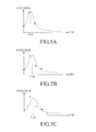
- FIG. 5A is a graph illustrating an estimation model which is estimated with three pieces of edge value data when the focus lens moves three times
- FIG. 5B is a graph illustrating an estimation model which is estimated with four pieces of edge value data when the focus lens moves four times
- FIG. 5A is a graph illustrating an estimation model which is estimated with five pieces of edge value data when the focus lens moves five times.
- step 640 it is determined if the difference between the peak value though the estimation model calculated at the previous position of the lens and the peak value though the estimation model calculated at the current position of the lens is less than or equal to a preset threshold value.
- FIGS. 5A to 5C illustrate estimation models calculated whenever the number of pieces of sample data increases in the auto-focus control method.
- FIG. 6 is a graph illustrating peak values obtained through estimation models according to the positions (steps) of the focus lens. According to an embodiment of the present invention, when a difference between a current peak value and a previous peak value is less than or equal to a preset threshold value ⁇ x th , the current position corresponding to the current peak value is determined to be a focused position. That is, referring to FIG.
- a difference between the peak value of a fourth position and the peak value of a third position, which is a previous peak value, is less than the preset threshold value, so that the focus lens is moved and stopped at the position at which the fourth peak value has been detected.
- step 640 when the difference between the peak value though the estimation model calculated at the previous position of the lens and the peak value though the estimation model calculated at the current position of the lens is greater than the preset threshold value, the procedure proceeds to step 650.
- step 650 the focus lens moves by a preset interval, and the process returns to steps 620 and 630 in which a new estimation model is calculated, a peak value is obtained, and then the procedure returns to step 640.
- step 640 When the difference between the peak value through the estimation model calculated at the previous position of the lens and the peak value through the estimation model calculated at the current position of the lens is less than or equal to the preset threshold value as a result of step 640, the calculation for the estimation is terminated, the focus lens moves to an estimated position, photographing is performed, and then the procedure is terminated.
- Equation (7) "w” represents a weight, “y” represents an estimation model, and “i” represents a sampling order from one to n.
- Equation (7) is expressed in a matrix form as shown in Equation (8) below, and a peak value can be calculated through the use of a pseudo-inverse matrix as shown in Equation (9) below.
- Equations (8) and (9) represent coefficients of an estimation model of an inverse matrix of a quadratic polynomial function. In this case, a peak value can be calculated by Equation (6) as well.
- the movement of the lens for an auto-focus control is minimized in a digital camera, so that the user of the digital camera can rapidly take a desired photograph without missing a moment.
Abstract
Description
- The present invention relates generally to a digital camera, and more particularly, to a method and apparatus for auto-focus control of a digital camera.
- Recently, digital cameras, in general, and in particular high-pixel digital cameras installed in mobile devices, such as cellular phones, have an auto-focus function for automatically focusing the lens when taking a photograph.
- Generally, such an auto-focus control method is one of a phase-difference detection scheme typically employed in Digital Single Lens Reflex (DSLR) cameras, and a contrast detection scheme typically employed in compact digital cameras and cellular phone cameras. The phase-difference detection scheme distributes light, which has passed through a lens, between a viewfinder and an auto-focus (AF) sensor through a mirror, to separate light which is incident on the AF sensor in two directions on a focus surface, to detect both beams of light by means of a line sensor, and to determine if the camera is focusing on a foreground or a background. Such a phase-difference detection scheme requires a lens system and a separate sensor for auto-focusing.
- The contrast detection scheme is based on a hill climbing method for finding a position at which an edge value is a maximum while moving a focus lens in given steps within an entire movable range of the focus lens or a part of the movable range.
FIG. 1 schematically illustrates the operation of an auto-focus control method using a normal contrast detection scheme. As shown inFIG. 1A , the contrast detection scheme is implemented in such a manner as to trace a change in an edge value, which is obtained by filtering an electrical signal given from an image sensor, according to each position while moving a focus lens at the same intervals, and to move the focus lens to a focus position where the highest focus value is obtained according to a result of the tracing, as shown inFIG. 1B . - In such conventional technologies, it is important to find a position having a maximum value without a large error while controlling an interval between positions between which a lens moves and a movement direction of the lens. However, as a higher accuracy and a high success rate are required, a processing time and the number of positions required for edge value sampling increase. In this case, an auto-focus control time increases, so that an interval between a photographing time point intended by the photographer and a time point at which a photograph is actually taken after auto-focus control may be longer. In particular, since an exposure time of an image sensor becomes longer under a low illumination, the operation time of the auto-focus control further increases.
- Accordingly, the present invention has been made to solve the above-mentioned problems occurring in the prior art, and the present invention provides an auto-focus control method and apparatus for rapidly achieving an auto-focus control in a digital camera.
- In accordance with an aspect of the present invention, there is provided a method for auto-focus control of a digital camera, the method including moving a focus lens of the digital camera to a position for a longest-distance photographing, and then extracting an edge value according to a corresponding position while moving the focus lens by a preset interval in a direction toward an image sensor; estimating a form of a preset function based on the extracted edge values, and calculating a maximum value of the estimated function; calculating a difference between a maximum value of the preset function calculated at a first current position of the focus lens and a maximum value of the preset function calculated at a previous position of the focus lens; and moving the focus lens to a position corresponding to a currently-calculated maximum value of the preset function when the difference between the maximum value of the preset function calculated at the first current position of the focus lens and the maximum value of the preset function calculated at the previous position of the focus lens is less than or equal to a preset threshold value.
- In accordance with another aspect of the present invention, there is provided an apparatus for auto-focus control of a digital camera, the apparatus including a lens unit configured with a zoom lens and a focus lens which is movable along an optical axis in order to focus an optical image formed on an image sensor, the lens unit allowing an optical image of a subject to be formed on the image sensor; an image sensor unit for converting image information of the subject into an electrical signal; an image signal processor (ISP) for extracting an edge value from the electrical signal, into which the image information has been converted; a driving unit for physically moving the lens unit according to a control signal received from a controller; and the controller for controlling the driving unit to move the focus lens of the digital camera to a position for a longest-distance photographing, extracting an edge value according to a corresponding position while moving the focus lens by a preset interval in a direction toward the image sensor, estimating a form of a preset function based on the extracted edge values, calculating a maximum value of the estimated function, calculating a difference between a maximum value of the preset function calculated at a first current position of the focus lens and a maximum value of the preset function calculated at a previous position of the focus lens, and controlling the focus lens to move to a position corresponding to a currently-calculated maximum value of the preset function when the difference between the maximum value of the preset function calculated at the first current position of the focus lens and the maximum value of the preset function calculated at the previous position of the focus lens is less than or equal to a preset threshold value.
- The above and other aspects, features and advantages of the present invention will be more apparent from the following detailed description taken in conjunction with the accompanying drawings, in which:
-
FIGs. 1A and 1B schematically illustrate the operation of an auto-focus control method using a normal contrast detection scheme; -
FIG. 2 is a block diagram illustrating the configuration of an auto-focus control apparatus according to an embodiment of the present invention; -
FIG. 3 is a flowchart illustrating the flow of the auto-focus control operation according to an embodiment of the present invention; -
FIG. 4 is a graph illustrating an example of an estimation model of the quadratic polynomial function's inverse function obtained from sample data in the auto-focus control method according to an embodiment of the present invention; -
FIGs. 5A to 5C are graphs illustrating estimation models calculated whenever the number of pieces of sample data increases in the auto-focus control method according to an embodiment of the present invention; and -
FIG. 6 is a graph illustrating peak values obtained through estimation models according to the positions (steps) of the focus lens. - Hereinafter, an apparatus and method according to embodiments of the present invention will be described with reference to the accompanying drawings. In the below description, many particular items such as a detailed component device are shown, but these are given only for providing a general understanding of the present invention. It will be understood by those skilled in the art that various changes in form and detail may be made within the scope of the present invention. Further, in the following description of the present invention, a detailed description of known functions and configurations incorporated herein will be omitted when it may make the subject matter of the present invention rather unclear.
- The present invention provides a method and apparatus for achieving rapidly an auto-focus control in a digital camera, which will be described in detail with reference to the accompanying drawings.
-
FIG. 2 is a block diagram illustrating the configuration of an auto-focus control apparatus according to an embodiment of the present invention. Referring toFIG. 2 , the auto-focus control apparatus according to an embodiment of the present invention includes alens unit 110, animage sensor unit 120, an image signal processor (ISP) 130, acontroller 140, adisplay unit 150, adriving unit 170, and aninput unit 160. - The
lens unit 110 forms an optical image of a subject on theimage sensor unit 120. Thelens unit 110 includes a zoom lens (not shown), and a focus lens (not shown) which is movable along an optical axis in order to focus the optical image formed on the image sensor unit. Through thelens unit 110, a digital image of a subject desired to be photographed by the user is obtained. - The
image sensor unit 120 may include a complementary metal-oxide semiconductor (CMOS), a charge-coupled device (CCD), etc. Theimage sensor unit 120 is implemented in a form where a plurality of photo-detectors are integrated as the respective pixels, and converts image information of a subject into an electrical signal and then transfers the electrical data to theISP 130. - The
ISP 130 processes an image signal, which has been input from theimage sensor unit 120, in units of frames. Also, according to an embodiment of the present invention, theISP 130 extracts an edge value from the electrical signal, into which the image information has been converted. - The
display unit 150 displays an image photographed according to the control of thecontroller 140. - The
input unit 160 receives and transfers the user's input to thecontroller 140. When thedisplay unit 150 is implemented with a touch screen, thedisplay unit 150 can operate as an input unit. - The
controller 140 controls the respective components of the digital camera. Thecontroller 140 estimates a position having the maximum edge value from given edge value information, and outputs a control signal to thedriving unit 170 to move the lens system to the estimated position. - Also, after controlling the
driving unit 170 to move the focus lens of the digital camera to a position for the longest-distance photographing, thecontroller 140 extracts edge values through theISP 130 according to each corresponding position while moving the focus lens by a preset interval, estimates a function having the form of an inverse function of a quadratic polynomial function based on the extracted edge values, and calculates the maximum value of the estimated function. - Then, the
controller 140 moves the focus lens by the preset interval, extracts an edge value according to a corresponding position, again estimates a form of a function through the use of data, which contains the edge value extracted according to the current position of the focus lens, and the previously-extracted edge values, and calculates a difference between the maximum value of the quadratic polynomial function's inverse function calculated/estimated at the current position of the focus lens, and the maximum value of the quadratic polynomial function's inverse function calculated/estimated at a previous position of the focus lens. - Next, when the difference between the maximum value of the quadratic polynomial function's inverse function calculated/estimated at the current position of the focus lens, and the maximum value of the quadratic polynomial function's inverse function calculated/estimated at the previous position of the focus lens is less than or equal to a preset threshold value, the
controller 140 controls thedriving unit 170 to move the focus lens to the current position having the maximum value of the quadratic polynomial function's inverse function which is currently calculated/estimated. - The
driving unit 170 physically moves thelens unit 110 according to a control signal received from thecontroller 140. - The digital camera may further include a buffer (not shown) for temporarily storing an image obtained through a photographing process.
-
FIG. 3 is a flowchart illustrating the flow of the auto-focus control operation according to an embodiment of the present invention. Referring toFIG. 3 , first, when an auto-focus control operation is executed, thecontroller 140 controls thedriving unit 170 to move a focus lens to a position for the longest-distance photographing, and measures edge value data of corresponding positions while moving the focus lens by the preset interval from a corresponding position in a direction toward theimage sensor 120 instep 610. In this case, while the focus lens moves at least three times, an edge value is extracted at each position. - Next, in
step 620, an estimation model having the form of the quadratic polynomial function's inverse function is calculated through the use of the measured edge value data, and a peak value, that represents a position having the maximum value of the estimated function, is detected. According to an embodiment of the present invention, if the focus lens moves three times, three edge values are sampled, and an estimation mode is calculated through the use of the sampled edge value data. The calculation of the estimation model is performed in such a manner as to perform a fitting to a preset function through the use of an inverse matrix, and to calculate a position having the maximum value from a coefficient value of the fitted function. An estimation model having the form of the quadratic polynomial function's inverse function may be expressed as Equation (1) below.
- In Equation (1), "a, b, c" represents the coefficient of quadratic polynomial function.
- According to an embodiment of the present invention, in order to calculate an estimation model, an operation is performed in a least square method using a pseudo-inverse matrix. First, in order to obtain an estimation model as shown in Equation (1), a function for each edge value may be expressed as Equation (2) below.

- Equation (2) represents equations for n pairs of edge values (xn, yn) and positions of n edge value points. Equation (2) may be expressed in a matrix form, as shown in Equation (3) below.

- Next, Equation (3) may be simplified to Equation (4) below.


- When Equation (3) is expressed as Equation (4), a coefficient value for an estimation model is obtained from a pseudo-inverse matrix of A, as shown in Equation (5). In this case, a position having a peak value becomes "-b/2a," as shown in Equation (6) below.

-
FIG. 4 is a graph illustrating an example of an estimation model of the quadratic polynomial function's inverse function obtained from sample data in the auto-focus control method according to an embodiment of the present invention. The estimation model as shown inFIG. 4 may be calculated through the use of edge value data. - Referring back to
FIG. 3 , instep 630, an edge value is measured after the lens moves by a preset next interval, and a new fitted estimation model is calculated through the use of edge value data including the measured edge value. As the number of sampled edge values increases according to a new step interval, the shape of a fitted graph varies, and the position of a peak value varies, too.FIGs. 5A to 5C are graphs illustrating estimation models calculated whenever the number of pieces of sample data increases in the auto-focus control method according to an embodiment of the present invention. As shown inFIGs. 5A to 5C , as the focus lens moves by a preset interval, an estimation model having the form of the quadratic polynomial function's inverse function is newly calculated, and a corresponding peak value is obtained.FIG. 5A is a graph illustrating an estimation model which is estimated with three pieces of edge value data when the focus lens moves three times,FIG. 5B is a graph illustrating an estimation model which is estimated with four pieces of edge value data when the focus lens moves four times, andFIG. 5A is a graph illustrating an estimation model which is estimated with five pieces of edge value data when the focus lens moves five times. When a new estimation model is calculated, a difference between a peak value though an estimation model calculated at a previous position of the lens and a peak value though an estimation model calculated at the current position of the lens is calculated. - Next, in
step 640, it is determined if the difference between the peak value though the estimation model calculated at the previous position of the lens and the peak value though the estimation model calculated at the current position of the lens is less than or equal to a preset threshold value. As indicated above,FIGS. 5A to 5C illustrate estimation models calculated whenever the number of pieces of sample data increases in the auto-focus control method.FIG. 6 is a graph illustrating peak values obtained through estimation models according to the positions (steps) of the focus lens. According to an embodiment of the present invention, when a difference between a current peak value and a previous peak value is less than or equal to a preset threshold value Δx th , the current position corresponding to the current peak value is determined to be a focused position. That is, referring toFIG. 6 , a difference between the peak value of a fourth position and the peak value of a third position, which is a previous peak value, is less than the preset threshold value, so that the focus lens is moved and stopped at the position at which the fourth peak value has been detected. - In
step 640, when the difference between the peak value though the estimation model calculated at the previous position of the lens and the peak value though the estimation model calculated at the current position of the lens is greater than the preset threshold value, the procedure proceeds to step 650. Instep 650, the focus lens moves by a preset interval, and the process returns tosteps - When the difference between the peak value through the estimation model calculated at the previous position of the lens and the peak value through the estimation model calculated at the current position of the lens is less than or equal to the preset threshold value as a result of
step 640, the calculation for the estimation is terminated, the focus lens moves to an estimated position, photographing is performed, and then the procedure is terminated. - Meanwhile, when an estimation model is calculated using the least square method according to an embodiment of the present invention, there is a problem in that a small error is amplified. Such a problem can be solved by giving a higher weight to the periphery of a peak through the use of a weighted least square method. The weighted least square method is calculated by Equation (7) below.

- In Equation (7), "w" represents a weight, "y" represents an estimation model, and "i" represents a sampling order from one to n.
- Equation (7) is expressed in a matrix form as shown in Equation (8) below, and a peak value can be calculated through the use of a pseudo-inverse matrix as shown in Equation (9) below.


- In Equations (8) and (9), "a," "b," and "c" represent coefficients of an estimation model of an inverse matrix of a quadratic polynomial function. In this case, a peak value can be calculated by Equation (6) as well.
- According to an embodiment of the present invention, the movement of the lens for an auto-focus control is minimized in a digital camera, so that the user of the digital camera can rapidly take a desired photograph without missing a moment.
- In addition, according to an embodiment of the present invention, it is possible to achieve a faster auto-focusing through improvement of an algorithm, even without a change in the characteristics or configuration of the basic components, including an electric actuator, an image signal processor (ISP), etc, which are used in the current camera module.
- The operation and configuration of the auto-focus control method and apparatus of a digital camera according to an embodiment of the present invention can be implemented as described above. While the invention has been shown and described with reference to certain embodiments thereof, it will be understood by those skilled in the art that various changes in form and details may be made therein without departing from the spirit and scope of the invention as defined by the appended claims.
Claims (11)
- A method for auto-focus control of a digital camera, the method comprising the steps of:moving a focus lens of the digital camera to a position for a longest-distance photographing, and then extracting an edge value according to a corresponding position while moving the focus lens by a preset interval in a direction toward an image sensor;estimating a form of a preset function based on the extracted edge values, and calculating a maximum value of the estimated function;calculating a difference between a maximum value of the preset function calculated at a first current position of the focus lens and a maximum value of the preset function calculated at a previous position of the focus lens; andmoving the focus lens to a position corresponding to a currently-calculated maximum value of the preset function when the difference between the maximum value of the preset function calculated at the first current position of the focus lens and the maximum value of the preset function calculated at the previous position of the focus lens is less than or equal to a preset threshold value.
- The method as claimed in claim 1, further comprising moving the focus lens by the preset interval when the difference between the maximum value of the preset function calculated at the first current position of the focus lens and the maximum value of the preset function calculated at the previous position of the focus lens is greater than the preset threshold value, extracting an edge value according to a corresponding position, and again estimating a form of the preset function through use of data of the edge value extracted according to a second current position of the focus lens and previously extracted edge values.
- The method as claimed in one of claims 1 to 2, wherein moving a focus lens of the digital camera to a position for a longest-distance photographing, and then extracting an edge value according to a corresponding position while moving the focus lens by a preset interval includes moving the focus lens of the digital camera to the position for the longest-distance photographing, and then extracting an edge value at every position while successively moving the focus lens by the preset interval at least three times.
- The method as claimed in one of claims 1 to 3, wherein the preset function corresponds to an inverse function of a quadratic polynomial function.
- The method as claimed in claim 4, wherein estimating a form of a preset function based on the extracted edge values and calculating a maximum value of the estimated function includes setting a model function for a matrix operation to ax 2 + bx + c=1/y and calculating values of coefficients a, b, c of the inverse function of the quadratic polynomial function through use of a pseudo-inverse matrix in order to estimate a form of the inverse function of the quadratic polynomial function based on the extracted edge values, and obtaining a maximum value from the calculated coefficient values.
- An apparatus for auto-focus control of a digital camera, the apparatus comprising:a lens unit configured with a focus lens which is movable along an optical axis in order to focus an optical image formed on an image sensor, the lens unit allowing the optical image of a subject to be formed on the image sensor;an image sensor unit for converting image information of the subject into an electrical signal;an image signal processor (ISP) for extracting an edge value from the electrical signal, into which the image information has been converted;a driving unit for physically moving the lens unit according to a control signal received from a controller; andthe controller for controlling the driving unit to move the focus lens of the digital camera to a position for a longest-distance photographing, extracting an edge value according to a corresponding position while moving the focus lens by a preset interval in a direction toward the image sensor, estimating a form of a preset function based on the extracted edge values, calculating a maximum value of the estimated function, calculating a difference between a maximum value of the preset function calculated at a first current position of the focus lens and a maximum value of the preset function calculated at a previous position of the focus lens, and controlling the focus lens to move to a position corresponding to a currently-calculated maximum value of the preset function when the difference between the maximum value of the preset function calculated at the first current position of the focus lens and the maximum value of the preset function calculated at the previous position of the focus lens is less than or equal to a preset threshold value.
- The apparatus as claimed in claim 6, wherein, when the difference between the maximum value of the preset function calculated at the first current position of the focus lens and the maximum value of the preset function calculated at the previous position of the focus lens is greater than the preset threshold value, the controller performs a control operation to move the focus lens by the preset interval, extract an edge value according to a corresponding position, and again estimate a form of the preset function through use of data of the edge value extracted according to a second current position of the focus lens and previously extracted edge values.
- The apparatus as claimed in one of claims 6 to 7, wherein, when the controller moves the focus lens of the digital camera to the position for the longest-distance photographing, and extracts an edge value according to a corresponding position while moving the focus lens by the preset interval, the controller moves the focus lens of the digital camera to the position for the longest-distance photographing, and extracts an edge value at every position while successively moving the focus lens by the preset interval at least three times.
- The apparatus as claimed in one of claims 6 to 8, wherein the preset function corresponds to an inverse function of a quadratic polynomial function.
- The apparatus as claimed in claim 9, wherein, when the controller estimates a form of a preset function based on the extracted edge values and calculates a maximum value of the estimated function, the controller sets a model function for a matrix operation to ax 2 + bx + c=1/y and calculates values of coefficients a, b, c of the inverse function of the quadratic polynomial function through use of a pseudo-inverse matrix in order to estimate a form of the inverse function of the quadratic polynomial function based on the extracted edge values, and obtains a maximum value from the calculated coefficient values.
- The apparatus as claimed in one of the claims 6 to 8, wherein the lens unit is further configured with a zoom lens.
Applications Claiming Priority (1)
| Application Number | Priority Date | Filing Date | Title |
|---|---|---|---|
| KR1020100002854A KR101137615B1 (en) | 2010-01-12 | 2010-01-12 | Auto focus method and apparatus of digital camera |
Publications (2)
| Publication Number | Publication Date |
|---|---|
| EP2357793A1 true EP2357793A1 (en) | 2011-08-17 |
| EP2357793B1 EP2357793B1 (en) | 2013-03-13 |
Family
ID=43876997
Family Applications (1)
| Application Number | Title | Priority Date | Filing Date |
|---|---|---|---|
| EP10195833A Not-in-force EP2357793B1 (en) | 2010-01-12 | 2010-12-20 | Method and apparatus for auto-focus control of digital camera |
Country Status (4)
| Country | Link |
|---|---|
| US (1) | US8315512B2 (en) |
| EP (1) | EP2357793B1 (en) |
| KR (1) | KR101137615B1 (en) |
| CN (1) | CN102131052B (en) |
Families Citing this family (11)
| Publication number | Priority date | Publication date | Assignee | Title |
|---|---|---|---|---|
| JP5919436B2 (en) * | 2013-06-06 | 2016-05-18 | 富士フイルム株式会社 | Auto-focus device and operation control method thereof |
| CN103424851B (en) * | 2013-08-22 | 2015-07-22 | 福建福光数码科技有限公司 | High-resolution and long-and-variable-focus airborne camera lens with automatic focusing and automatic dimming functions |
| JP6512814B2 (en) * | 2014-12-16 | 2019-05-15 | キヤノン株式会社 | CONTROL DEVICE, OPTICAL DEVICE, IMAGING DEVICE, CONTROL METHOD, PROGRAM, AND STORAGE MEDIUM |
| CN109889721B (en) * | 2015-12-23 | 2021-01-29 | 北京奇虎科技有限公司 | Camera automatic focusing control method and device |
| KR102484349B1 (en) * | 2016-01-11 | 2023-01-04 | 한화테크윈 주식회사 | Camera focusing method |
| KR101850363B1 (en) * | 2016-02-16 | 2018-04-20 | 주식회사 이오테크닉스 | Photographing apparatus and photographing method |
| KR101993670B1 (en) * | 2016-03-17 | 2019-06-27 | 주식회사 이오테크닉스 | Photographing method and object alignment method using the photographing method |
| CN106094162B (en) * | 2016-08-26 | 2018-05-22 | 英华达(上海)科技有限公司 | A kind of focusing method |
| CN108416281B (en) * | 2018-02-28 | 2020-11-06 | 厦门云之拓科技有限公司 | Camera applied to iris recognition |
| US11885943B2 (en) * | 2019-10-30 | 2024-01-30 | Samsung Electronics Co., Ltd. | Lens assembly and electronic device including the same |
| CN114302052B (en) * | 2021-11-24 | 2024-02-02 | 影石创新科技股份有限公司 | Lens focusing method and device of image pickup apparatus, image pickup apparatus and storage medium |
Citations (4)
| Publication number | Priority date | Publication date | Assignee | Title |
|---|---|---|---|---|
| US5040228A (en) * | 1989-08-28 | 1991-08-13 | At&T Bell Laboratories | Method and apparatus for automatically focusing an image-acquisition device |
| US20040212721A1 (en) * | 2002-08-21 | 2004-10-28 | Nikon Corporation | Method for focus adjusting and camera |
| WO2005073895A1 (en) * | 2004-01-23 | 2005-08-11 | Intermec Ip Corp. | Autofocus barcode scanner and the like employing micro-fluidic lens |
| EP1691541A2 (en) * | 2005-02-14 | 2006-08-16 | Fujifilm Electronic Imaging Limited | Method and apparatus for estimating an in-focus position |
Family Cites Families (13)
| Publication number | Priority date | Publication date | Assignee | Title |
|---|---|---|---|---|
| JPS5882211A (en) * | 1981-11-12 | 1983-05-17 | Asahi Optical Co Ltd | Auto-focusing device |
| JPS59146008A (en) * | 1983-02-10 | 1984-08-21 | Olympus Optical Co Ltd | Focusing detector |
| JP2005331690A (en) | 2004-05-19 | 2005-12-02 | Sharp Corp | Focusing apparatus |
| KR100663744B1 (en) * | 2004-10-29 | 2007-01-02 | 엠텍비젼 주식회사 | Method and Apparatus for auto focusing using hysteresis curve |
| US7538813B2 (en) * | 2005-05-11 | 2009-05-26 | Sony Ericsson Mobile Communications Ab | Digital cameras with triangulation autofocus systems and related methods |
| US7835637B2 (en) * | 2006-09-20 | 2010-11-16 | Qualcomm Incorporated | Predictive focus value calculation for image capture devices |
| KR20080081693A (en) | 2007-03-06 | 2008-09-10 | 삼성전자주식회사 | Autofocus method for a camera |
| KR100897768B1 (en) * | 2007-05-01 | 2009-05-15 | 삼성전자주식회사 | An automatic focusing method and apparatus for using the same |
| EP2006733B1 (en) * | 2007-06-19 | 2013-05-22 | Samsung Electronics Co., Ltd. | Auto focus apparatus and method for camera |
| KR101295433B1 (en) | 2007-06-19 | 2013-08-09 | 삼성전자주식회사 | Auto focus apparatus and method for camera |
| KR100935320B1 (en) * | 2007-11-07 | 2010-01-06 | 삼성전기주식회사 | Auto focusing method |
| KR20090065891A (en) * | 2007-12-18 | 2009-06-23 | 삼성전기주식회사 | Method to control auto focus |
| US8199248B2 (en) * | 2009-01-30 | 2012-06-12 | Sony Corporation | Two-dimensional polynomial model for depth estimation based on two-picture matching |
-
2010
- 2010-01-12 KR KR1020100002854A patent/KR101137615B1/en active IP Right Grant
- 2010-12-20 EP EP10195833A patent/EP2357793B1/en not_active Not-in-force
-
2011
- 2011-01-11 US US13/004,472 patent/US8315512B2/en active Active
- 2011-01-12 CN CN201110005287.3A patent/CN102131052B/en not_active Expired - Fee Related
Patent Citations (4)
| Publication number | Priority date | Publication date | Assignee | Title |
|---|---|---|---|---|
| US5040228A (en) * | 1989-08-28 | 1991-08-13 | At&T Bell Laboratories | Method and apparatus for automatically focusing an image-acquisition device |
| US20040212721A1 (en) * | 2002-08-21 | 2004-10-28 | Nikon Corporation | Method for focus adjusting and camera |
| WO2005073895A1 (en) * | 2004-01-23 | 2005-08-11 | Intermec Ip Corp. | Autofocus barcode scanner and the like employing micro-fluidic lens |
| EP1691541A2 (en) * | 2005-02-14 | 2006-08-16 | Fujifilm Electronic Imaging Limited | Method and apparatus for estimating an in-focus position |
Also Published As
| Publication number | Publication date |
|---|---|
| KR101137615B1 (en) | 2012-04-19 |
| KR20110082913A (en) | 2011-07-20 |
| US20110170846A1 (en) | 2011-07-14 |
| US8315512B2 (en) | 2012-11-20 |
| CN102131052B (en) | 2015-07-15 |
| CN102131052A (en) | 2011-07-20 |
| EP2357793B1 (en) | 2013-03-13 |
Similar Documents
| Publication | Publication Date | Title |
|---|---|---|
| EP2357793B1 (en) | Method and apparatus for auto-focus control of digital camera | |
| KR101345012B1 (en) | Two-dimensional polynomial model for depth estimation based on two-picture matching | |
| EP2615484B1 (en) | Automatic focusing apparatus and method with calibration and slope correction | |
| WO2007058100A1 (en) | In-focus detector | |
| EP2511747B1 (en) | Imaging device and imaging method | |
| US8300137B2 (en) | Image sensing apparatus providing driving direction of focus lens for attaining in-focus state and control method therefor | |
| US7630622B2 (en) | Automatic focusing methods and image capture devices utilizing the same | |
| WO2007086378A1 (en) | Best-focus detector | |
| CN110022433B (en) | Image pickup apparatus, lens apparatus, and control method thereof | |
| US9794473B2 (en) | Imaging device, imaging device body, and lens barrel | |
| KR20090028255A (en) | Method and apparatus for auto focusing of image capturing | |
| JP6366295B2 (en) | Optical apparatus and control method | |
| JP2018004918A (en) | Focus adjustment device and method, and imaging apparatus | |
| US8294810B2 (en) | Assisting focusing method for face block | |
| JP2017067857A (en) | Focus detection device, prediction method, program and storage medium | |
| US9407811B2 (en) | Focus control unit in imaging apparatus, method of controlling the focus control unit and medium for controlling the focus control unit | |
| JP6808340B2 (en) | Lens control device, control method | |
| WO2013094551A1 (en) | Imaging device, method for controlling same, and program | |
| US10747089B2 (en) | Imaging apparatus and control method of the same | |
| CN106993110B (en) | Image pickup apparatus and control method thereof | |
| KR101510104B1 (en) | Method and apparatus for controlling phase difference auto focus | |
| JP5707983B2 (en) | Focus adjustment device and imaging device | |
| US8340513B2 (en) | Camera and method for performing auto-focusing | |
| JP2005338514A (en) | Lens controlling device and imaging equipment | |
| KR20100099556A (en) | Photographing apparatus and method of processing image in photographing apparatus |
Legal Events
| Date | Code | Title | Description |
|---|---|---|---|
| PUAI | Public reference made under article 153(3) epc to a published international application that has entered the european phase |
Free format text: ORIGINAL CODE: 0009012 |
|
| AK | Designated contracting states |
Kind code of ref document: A1 Designated state(s): AL AT BE BG CH CY CZ DE DK EE ES FI FR GB GR HR HU IE IS IT LI LT LU LV MC MK MT NL NO PL PT RO RS SE SI SK SM TR |
|
| AX | Request for extension of the european patent |
Extension state: BA ME |
|
| 17P | Request for examination filed |
Effective date: 20120217 |
|
| GRAP | Despatch of communication of intention to grant a patent |
Free format text: ORIGINAL CODE: EPIDOSNIGR1 |
|
| RAP1 | Party data changed (applicant data changed or rights of an application transferred) |
Owner name: SAMSUNG ELECTRONICS CO., LTD. |
|
| GRAS | Grant fee paid |
Free format text: ORIGINAL CODE: EPIDOSNIGR3 |
|
| GRAA | (expected) grant |
Free format text: ORIGINAL CODE: 0009210 |
|
| AK | Designated contracting states |
Kind code of ref document: B1 Designated state(s): AL AT BE BG CH CY CZ DE DK EE ES FI FR GB GR HR HU IE IS IT LI LT LU LV MC MK MT NL NO PL PT RO RS SE SI SK SM TR |
|
| REG | Reference to a national code |
Ref country code: GB Ref legal event code: FG4D |
|
| REG | Reference to a national code |
Ref country code: AT Ref legal event code: REF Ref document number: 601390 Country of ref document: AT Kind code of ref document: T Effective date: 20130315 Ref country code: CH Ref legal event code: EP |
|
| REG | Reference to a national code |
Ref country code: IE Ref legal event code: FG4D |
|
| REG | Reference to a national code |
Ref country code: DE Ref legal event code: R096 Ref document number: 602010005426 Country of ref document: DE Effective date: 20130508 |
|
| PG25 | Lapsed in a contracting state [announced via postgrant information from national office to epo] |
Ref country code: SE Free format text: LAPSE BECAUSE OF FAILURE TO SUBMIT A TRANSLATION OF THE DESCRIPTION OR TO PAY THE FEE WITHIN THE PRESCRIBED TIME-LIMIT Effective date: 20130313 Ref country code: NO Free format text: LAPSE BECAUSE OF FAILURE TO SUBMIT A TRANSLATION OF THE DESCRIPTION OR TO PAY THE FEE WITHIN THE PRESCRIBED TIME-LIMIT Effective date: 20130613 Ref country code: BG Free format text: LAPSE BECAUSE OF FAILURE TO SUBMIT A TRANSLATION OF THE DESCRIPTION OR TO PAY THE FEE WITHIN THE PRESCRIBED TIME-LIMIT Effective date: 20130613 Ref country code: LT Free format text: LAPSE BECAUSE OF FAILURE TO SUBMIT A TRANSLATION OF THE DESCRIPTION OR TO PAY THE FEE WITHIN THE PRESCRIBED TIME-LIMIT Effective date: 20130313 Ref country code: ES Free format text: LAPSE BECAUSE OF FAILURE TO SUBMIT A TRANSLATION OF THE DESCRIPTION OR TO PAY THE FEE WITHIN THE PRESCRIBED TIME-LIMIT Effective date: 20130624 |
|
| REG | Reference to a national code |
Ref country code: NL Ref legal event code: T3 |
|
| REG | Reference to a national code |
Ref country code: AT Ref legal event code: MK05 Ref document number: 601390 Country of ref document: AT Kind code of ref document: T Effective date: 20130313 |
|
| REG | Reference to a national code |
Ref country code: LT Ref legal event code: MG4D |
|
| PG25 | Lapsed in a contracting state [announced via postgrant information from national office to epo] |
Ref country code: GR Free format text: LAPSE BECAUSE OF FAILURE TO SUBMIT A TRANSLATION OF THE DESCRIPTION OR TO PAY THE FEE WITHIN THE PRESCRIBED TIME-LIMIT Effective date: 20130614 Ref country code: FI Free format text: LAPSE BECAUSE OF FAILURE TO SUBMIT A TRANSLATION OF THE DESCRIPTION OR TO PAY THE FEE WITHIN THE PRESCRIBED TIME-LIMIT Effective date: 20130313 Ref country code: LV Free format text: LAPSE BECAUSE OF FAILURE TO SUBMIT A TRANSLATION OF THE DESCRIPTION OR TO PAY THE FEE WITHIN THE PRESCRIBED TIME-LIMIT Effective date: 20130313 Ref country code: SI Free format text: LAPSE BECAUSE OF FAILURE TO SUBMIT A TRANSLATION OF THE DESCRIPTION OR TO PAY THE FEE WITHIN THE PRESCRIBED TIME-LIMIT Effective date: 20130313 |
|
| PG25 | Lapsed in a contracting state [announced via postgrant information from national office to epo] |
Ref country code: HR Free format text: LAPSE BECAUSE OF FAILURE TO SUBMIT A TRANSLATION OF THE DESCRIPTION OR TO PAY THE FEE WITHIN THE PRESCRIBED TIME-LIMIT Effective date: 20130313 Ref country code: RS Free format text: LAPSE BECAUSE OF FAILURE TO SUBMIT A TRANSLATION OF THE DESCRIPTION OR TO PAY THE FEE WITHIN THE PRESCRIBED TIME-LIMIT Effective date: 20130313 Ref country code: BE Free format text: LAPSE BECAUSE OF FAILURE TO SUBMIT A TRANSLATION OF THE DESCRIPTION OR TO PAY THE FEE WITHIN THE PRESCRIBED TIME-LIMIT Effective date: 20130313 |
|
| PG25 | Lapsed in a contracting state [announced via postgrant information from national office to epo] |
Ref country code: IS Free format text: LAPSE BECAUSE OF FAILURE TO SUBMIT A TRANSLATION OF THE DESCRIPTION OR TO PAY THE FEE WITHIN THE PRESCRIBED TIME-LIMIT Effective date: 20130713 Ref country code: EE Free format text: LAPSE BECAUSE OF FAILURE TO SUBMIT A TRANSLATION OF THE DESCRIPTION OR TO PAY THE FEE WITHIN THE PRESCRIBED TIME-LIMIT Effective date: 20130313 Ref country code: AT Free format text: LAPSE BECAUSE OF FAILURE TO SUBMIT A TRANSLATION OF THE DESCRIPTION OR TO PAY THE FEE WITHIN THE PRESCRIBED TIME-LIMIT Effective date: 20130313 Ref country code: RO Free format text: LAPSE BECAUSE OF FAILURE TO SUBMIT A TRANSLATION OF THE DESCRIPTION OR TO PAY THE FEE WITHIN THE PRESCRIBED TIME-LIMIT Effective date: 20130313 Ref country code: PT Free format text: LAPSE BECAUSE OF FAILURE TO SUBMIT A TRANSLATION OF THE DESCRIPTION OR TO PAY THE FEE WITHIN THE PRESCRIBED TIME-LIMIT Effective date: 20130715 Ref country code: SK Free format text: LAPSE BECAUSE OF FAILURE TO SUBMIT A TRANSLATION OF THE DESCRIPTION OR TO PAY THE FEE WITHIN THE PRESCRIBED TIME-LIMIT Effective date: 20130313 Ref country code: CZ Free format text: LAPSE BECAUSE OF FAILURE TO SUBMIT A TRANSLATION OF THE DESCRIPTION OR TO PAY THE FEE WITHIN THE PRESCRIBED TIME-LIMIT Effective date: 20130313 |
|
| PG25 | Lapsed in a contracting state [announced via postgrant information from national office to epo] |
Ref country code: PL Free format text: LAPSE BECAUSE OF FAILURE TO SUBMIT A TRANSLATION OF THE DESCRIPTION OR TO PAY THE FEE WITHIN THE PRESCRIBED TIME-LIMIT Effective date: 20130313 |
|
| PLBE | No opposition filed within time limit |
Free format text: ORIGINAL CODE: 0009261 |
|
| STAA | Information on the status of an ep patent application or granted ep patent |
Free format text: STATUS: NO OPPOSITION FILED WITHIN TIME LIMIT |
|
| PG25 | Lapsed in a contracting state [announced via postgrant information from national office to epo] |
Ref country code: DK Free format text: LAPSE BECAUSE OF FAILURE TO SUBMIT A TRANSLATION OF THE DESCRIPTION OR TO PAY THE FEE WITHIN THE PRESCRIBED TIME-LIMIT Effective date: 20130313 |
|
| 26N | No opposition filed |
Effective date: 20131216 |
|
| PG25 | Lapsed in a contracting state [announced via postgrant information from national office to epo] |
Ref country code: IT Free format text: LAPSE BECAUSE OF FAILURE TO SUBMIT A TRANSLATION OF THE DESCRIPTION OR TO PAY THE FEE WITHIN THE PRESCRIBED TIME-LIMIT Effective date: 20130313 |
|
| REG | Reference to a national code |
Ref country code: DE Ref legal event code: R097 Ref document number: 602010005426 Country of ref document: DE Effective date: 20131216 |
|
| PG25 | Lapsed in a contracting state [announced via postgrant information from national office to epo] |
Ref country code: LU Free format text: LAPSE BECAUSE OF FAILURE TO SUBMIT A TRANSLATION OF THE DESCRIPTION OR TO PAY THE FEE WITHIN THE PRESCRIBED TIME-LIMIT Effective date: 20131220 |
|
| REG | Reference to a national code |
Ref country code: IE Ref legal event code: MM4A |
|
| REG | Reference to a national code |
Ref country code: FR Ref legal event code: ST Effective date: 20140829 |
|
| PG25 | Lapsed in a contracting state [announced via postgrant information from national office to epo] |
Ref country code: IE Free format text: LAPSE BECAUSE OF NON-PAYMENT OF DUE FEES Effective date: 20131220 |
|
| PG25 | Lapsed in a contracting state [announced via postgrant information from national office to epo] |
Ref country code: FR Free format text: LAPSE BECAUSE OF NON-PAYMENT OF DUE FEES Effective date: 20131231 |
|
| PG25 | Lapsed in a contracting state [announced via postgrant information from national office to epo] |
Ref country code: MC Free format text: LAPSE BECAUSE OF FAILURE TO SUBMIT A TRANSLATION OF THE DESCRIPTION OR TO PAY THE FEE WITHIN THE PRESCRIBED TIME-LIMIT Effective date: 20130313 |
|
| PG25 | Lapsed in a contracting state [announced via postgrant information from national office to epo] |
Ref country code: SM Free format text: LAPSE BECAUSE OF FAILURE TO SUBMIT A TRANSLATION OF THE DESCRIPTION OR TO PAY THE FEE WITHIN THE PRESCRIBED TIME-LIMIT Effective date: 20130313 |
|
| PG25 | Lapsed in a contracting state [announced via postgrant information from national office to epo] |
Ref country code: CY Free format text: LAPSE BECAUSE OF FAILURE TO SUBMIT A TRANSLATION OF THE DESCRIPTION OR TO PAY THE FEE WITHIN THE PRESCRIBED TIME-LIMIT Effective date: 20130313 Ref country code: TR Free format text: LAPSE BECAUSE OF FAILURE TO SUBMIT A TRANSLATION OF THE DESCRIPTION OR TO PAY THE FEE WITHIN THE PRESCRIBED TIME-LIMIT Effective date: 20130313 |
|
| PG25 | Lapsed in a contracting state [announced via postgrant information from national office to epo] |
Ref country code: MK Free format text: LAPSE BECAUSE OF FAILURE TO SUBMIT A TRANSLATION OF THE DESCRIPTION OR TO PAY THE FEE WITHIN THE PRESCRIBED TIME-LIMIT Effective date: 20130313 Ref country code: HU Free format text: LAPSE BECAUSE OF FAILURE TO SUBMIT A TRANSLATION OF THE DESCRIPTION OR TO PAY THE FEE WITHIN THE PRESCRIBED TIME-LIMIT; INVALID AB INITIO Effective date: 20101220 |
|
| REG | Reference to a national code |
Ref country code: CH Ref legal event code: PL |
|
| PG25 | Lapsed in a contracting state [announced via postgrant information from national office to epo] |
Ref country code: MT Free format text: LAPSE BECAUSE OF FAILURE TO SUBMIT A TRANSLATION OF THE DESCRIPTION OR TO PAY THE FEE WITHIN THE PRESCRIBED TIME-LIMIT Effective date: 20130313 |
|
| PG25 | Lapsed in a contracting state [announced via postgrant information from national office to epo] |
Ref country code: LI Free format text: LAPSE BECAUSE OF NON-PAYMENT OF DUE FEES Effective date: 20141231 Ref country code: CH Free format text: LAPSE BECAUSE OF NON-PAYMENT OF DUE FEES Effective date: 20141231 |
|
| PGFP | Annual fee paid to national office [announced via postgrant information from national office to epo] |
Ref country code: DE Payment date: 20171121 Year of fee payment: 8 Ref country code: NL Payment date: 20171121 Year of fee payment: 8 |
|
| PGFP | Annual fee paid to national office [announced via postgrant information from national office to epo] |
Ref country code: GB Payment date: 20171121 Year of fee payment: 8 |
|
| PG25 | Lapsed in a contracting state [announced via postgrant information from national office to epo] |
Ref country code: AL Free format text: LAPSE BECAUSE OF FAILURE TO SUBMIT A TRANSLATION OF THE DESCRIPTION OR TO PAY THE FEE WITHIN THE PRESCRIBED TIME-LIMIT Effective date: 20130313 |
|
| REG | Reference to a national code |
Ref country code: DE Ref legal event code: R119 Ref document number: 602010005426 Country of ref document: DE |
|
| REG | Reference to a national code |
Ref country code: NL Ref legal event code: MM Effective date: 20190101 |
|
| GBPC | Gb: european patent ceased through non-payment of renewal fee |
Effective date: 20181220 |
|
| PG25 | Lapsed in a contracting state [announced via postgrant information from national office to epo] |
Ref country code: NL Free format text: LAPSE BECAUSE OF NON-PAYMENT OF DUE FEES Effective date: 20190101 |
|
| PG25 | Lapsed in a contracting state [announced via postgrant information from national office to epo] |
Ref country code: DE Free format text: LAPSE BECAUSE OF NON-PAYMENT OF DUE FEES Effective date: 20190702 |
|
| PG25 | Lapsed in a contracting state [announced via postgrant information from national office to epo] |
Ref country code: GB Free format text: LAPSE BECAUSE OF NON-PAYMENT OF DUE FEES Effective date: 20181220 |