EP2337005A1 - Simulator for centrifugal force for paragliding - Google Patents
Simulator for centrifugal force for paragliding Download PDFInfo
- Publication number
- EP2337005A1 EP2337005A1 EP10190022A EP10190022A EP2337005A1 EP 2337005 A1 EP2337005 A1 EP 2337005A1 EP 10190022 A EP10190022 A EP 10190022A EP 10190022 A EP10190022 A EP 10190022A EP 2337005 A1 EP2337005 A1 EP 2337005A1
- Authority
- EP
- European Patent Office
- Prior art keywords
- pilot
- suspension
- centrifugal force
- pivoting
- simulator
- Prior art date
- Legal status (The legal status is an assumption and is not a legal conclusion. Google has not performed a legal analysis and makes no representation as to the accuracy of the status listed.)
- Withdrawn
Links
Images


Classifications
-
- G—PHYSICS
- G09—EDUCATION; CRYPTOGRAPHY; DISPLAY; ADVERTISING; SEALS
- G09B—EDUCATIONAL OR DEMONSTRATION APPLIANCES; APPLIANCES FOR TEACHING, OR COMMUNICATING WITH, THE BLIND, DEAF OR MUTE; MODELS; PLANETARIA; GLOBES; MAPS; DIAGRAMS
- G09B9/00—Simulators for teaching or training purposes
- G09B9/02—Simulators for teaching or training purposes for teaching control of vehicles or other craft
- G09B9/08—Simulators for teaching or training purposes for teaching control of vehicles or other craft for teaching control of aircraft, e.g. Link trainer
- G09B9/10—Simulators for teaching or training purposes for teaching control of vehicles or other craft for teaching control of aircraft, e.g. Link trainer with simulated flight- or engine-generated force being applied to aircraft occupant
-
- G—PHYSICS
- G09—EDUCATION; CRYPTOGRAPHY; DISPLAY; ADVERTISING; SEALS
- G09B—EDUCATIONAL OR DEMONSTRATION APPLIANCES; APPLIANCES FOR TEACHING, OR COMMUNICATING WITH, THE BLIND, DEAF OR MUTE; MODELS; PLANETARIA; GLOBES; MAPS; DIAGRAMS
- G09B9/00—Simulators for teaching or training purposes
-
- G—PHYSICS
- G09—EDUCATION; CRYPTOGRAPHY; DISPLAY; ADVERTISING; SEALS
- G09B—EDUCATIONAL OR DEMONSTRATION APPLIANCES; APPLIANCES FOR TEACHING, OR COMMUNICATING WITH, THE BLIND, DEAF OR MUTE; MODELS; PLANETARIA; GLOBES; MAPS; DIAGRAMS
- G09B9/00—Simulators for teaching or training purposes
- G09B9/02—Simulators for teaching or training purposes for teaching control of vehicles or other craft
- G09B9/08—Simulators for teaching or training purposes for teaching control of vehicles or other craft for teaching control of aircraft, e.g. Link trainer
Definitions
- the invention relates to a training and training device for the paragliding (paragliding), that allows the pilot to get used in a very realistic manner to the occurring g-loads (centrifugal forces) during maneuvers in paragliding, to train them and safely the body to introduce these forces and visual impressions.
- Paragliding or paragliding is a flying sport in which the pilot can take a paraglider from a mountain and, using dynamic or thermal wind-ups without an engine, can be in the air for up to several hours, covering distances of more than 100 km.
- the paraglider Due to its low airspeed, the paraglider is a very agile aircraft, but also susceptible to weather changes. Wind speeds of 30 km / h, for many aircraft no problem, are already considered borderline for the paraglider.
- a paragliding flight simulator emerges, consisting essentially of three components that move relative to each other.
- a fixed ceiling anchorage including a rotating structure that can rotate the pilot 360 ° along its vertical axis (Z-axis), a slide that can perform linear reciprocating movements back and forth, and a balance device, the pilot at Bremsleinenyak tends to increase by raising the seatboard of the harness via motors.
- the body is brought "stationary" in an inclined position, but the forces occurring on the pilot body do not correspond to the forces occurring during flight.
- the real flight behavior of a Paragleitles be simulated in the turn, ie the forward tilting of the body of the pilot in the spiral fall.
- a simulator training provides a significant increase in the effective training time compared to the time spent (about 1: 500 to 1: 1000 in real flight, and about 1:10 in simulator training).
- the cost of achieving the same training effect when comparing real flight and simulator training is about 5 to 10% on the simulator.
- a pilot can achieve an effective training time with some training sessions, which he would achieve with real flights usually only over several years.
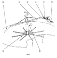
- the centrifugal simulator consists as in Fig.1 represented by the main components mounting frame (10), geared motor (20), rotor (30) connecting joint (40), coupling (50), pilot suspension (60), harness (70) and balance weight (80)
- the design of the speed of the rotor (30) and radius of the rotor (30) is chosen so that the product of radius and angular velocity, the centrifugal force, corresponds to those obtained in flight with the paraglider.
- the radius of the rotor (30) is less than the orbit radius in real flight, but the angular velocity of the geared motor (20) is greater. As a result, a smaller size of the centrifugal force simulator is achieved.
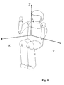
- the centrifugal force simulator is designed in such a way that the pilot, depending on the centrifugal force, occupies exactly the position in the space that he occupies during the flight. This is very important for the realistic simulation, since the centrifugal forces are divided into the three axes gx, gy and gz, which act along the axes x, y and z ( Fig. 6 ) have very different effects on the organism and therefore not only the resultant of these components may be considered but the direction of the individual components.
- a paraglider can be steered into a curve in two ways. Either by pulling on the control lines (61), or by shifting the center of gravity to one side. By this displacement, one of the two suspension points (65) moves upwards, the other down, the paraglider gets an asymmetric lift distribution and thereby rotates in the direction in which the center of gravity is shifted.
- the pilot suspension (60) is connected to the rotor (30) by the connecting joint (40).
- the lower bearing (40 X2) on the connecting joint (40) allows the pilot to apply the usual in-flight weight transfer to the centrifugal force simulator. This causes a substantial change in the distribution of the centrifugal force components gx, gy, and gz, which act on the body. Therefore, this is taken into account in the simulation. The resultant of the three g-components remains unchanged.
- each g-load is assigned a unique angle. (60 ° at 2 g, 90 ° would correspond to an infinite centrifugal force.)
- the rotation predominates around the longitudinal axis x of the pilot, at higher g loads, the pivotal movement about the vertical axis z of the pilot then predominates (view downwards).
- the pivoting of the pilot body about the longitudinal axis x in the storage (40 X1) is always smaller than 90 °, since 90 ° would correspond to a g-load of infinity.
- the rotation about the vertical axis z in the bearing (40Z) can be more than 90 °, the pilot then flies with the body in the spiral motion already with a backward component, which means the transition to the maneuver "SAT".
- a coupling (50) consisting of the coupling rod (51) and the coupling rod ( 52) between the rotor (30) and connecting joint (40) installed.
- the coupling causes the pilot body, which pivots outward with increasing rotation by the centrifugal force (40 X1), also pivots his gaze downward in flight.
- a change in the length of the coupling rod (51) and the coupling rod (52) and the angle between z-y plane of the pilot and the coupling rod (52) affects the interaction of the two rotational movements.
- the coupling of the two pivoting movements about the x- and z-axis of the pilot could also be realized by an electromechanical solution by means of servo motors and control technology.
- a paraglider has two so-called “brakes” or “steering lines” (61) to control it.
- the "control path” is the measure in centimeters how far the control line is pulled in. Basically, the brake force increase is in straight flight while pulling on the control lines (61) approximately linear, but slightly depending on the design features of the paraglider as well as the surface load (total weight relative to the projected wing)
- This braking force increase is realized by a Raffmati, in which a plurality of weights (62) are mounted one above the other and in each case the lowest weight is raised by train until it meets the next weight and this entrains.
- a stepped brake force increase is realized, but which is considered to be quasi-linear, since the human body can perceive the step-like increase in the load on the hand anyway.
- the simulation of the braking force increase with increasing control path could also be realized by an electromechanical solution by means of servo motors and control technology.
- the braking force increases with increasing g load.
- weights (62) By using weights (62) to simulate the braking force, braking force increase is achieved with increasing g-load since the same centrifugal force acts on the weights (62) as on the pilots. This would not be the case when using a spring.
- the simulation of the brake force increase with increasing g-load could also be realized by an electromechanical solution using actuators and control technology.
- the control lines (61) pass over deflection rollers (63), (64). On a pulley (64) a rotary potentiometer is attached, which provides the control signal for a frequency converter, which sets the geared motor (20) and thus the rotor (30) in rotation.
- a train at the Control line (61) causes the rotor (30) of the centrifugal force simulator to be accelerated and thereby the pilot is brought into the simulated position with corresponding g load.
- the braking force increases with increasing braking distance and increasing g-load.
- the centrifugal force simulator is able by the above-mentioned design details the position of the pilot according to the centrifugal force, the real flight according to realistic position. Only the radius and the angular velocity of the centrifugal simulator are changed in comparison to the real flight. The pilot also does not perform any real vertical movement on the centrifugal force simulator.
- the pilot does not see his immediate environment during training. He has a Virtual Reality Glasses (90), which contains two small high-resolution monitors and a corresponding optics.
- These virtual reality glasses (90) are equipped with infrared sensors, an already commercially available product, giving the pilot a virtual three-dimensional landscape. Due to the real situation, which are realized by the structural components of the centrifugal force simulator, the pilot now looks like in flight at the same angle on the landscape, as in flight.
- the receiver of the Virtual Reality glasses is located in the center of the centrifugal simulator. The slightly narrower radius on which the pilot rotates on the centrifugal simulator is irrelevant for the 3-d perception of his landscape.
- the receiver sensor of the virtual reality system is displaced about the z axis in the same direction as the rotor (30), so that the angular velocity between the pilot and the infrared receiver real angular velocity in flight equivalent.
- PC flight simulators which can also be operated with such virtual reality glasses.
- the landscape is displayed as a coordinate system and the movement in space only through the real movement of the Pilot on the centrifugal simulator results.
Abstract
Description
Die Erfindung betrifft ein Ausbildungs- und Trainingsgerät für den Bereich Paragleiten (Gleitschirmfliegen), dass es dem Piloten ermöglicht, sich in sehr realistischer Weise an die auftretenden g-Belastungen (Fliehkraftbelastungen) bei Flugmanövern beim Gleitschirmfliegen zu gewöhnen, diese zu trainieren und gefahrlos den Körper an diese Kräfte und visuellen Eindrücke heranzuführen.The invention relates to a training and training device for the paragliding (paragliding), that allows the pilot to get used in a very realistic manner to the occurring g-loads (centrifugal forces) during maneuvers in paragliding, to train them and safely the body to introduce these forces and visual impressions.
Parageiten oder auch Gleitschirmfliegen ist eine Flugsportart, bei dem der Pilot mit einem Gleitschirm von einem Berg startet und unter Nutzung von dynamischen oder thermischen Aufwinden ohne Motor bis zu mehreren Stunden in der Luft sein kann und Flugstrecken von weit mehr als 100 km zurücklegen kann.Paragliding or paragliding is a flying sport in which the pilot can take a paraglider from a mountain and, using dynamic or thermal wind-ups without an engine, can be in the air for up to several hours, covering distances of more than 100 km.
Durch seine geringe Fluggeschwindigkeit ist der Gleitschirm zum einen ein sehr wendiges Fluggerät, dadurch aber auch anfällig auf Wetteränderungen. Windgeschwindigkeiten von 30 km/h, für viele Fluggeräte kein Problem, sind für den Gleitschirm bereits als grenzwertig zu betrachten.Due to its low airspeed, the paraglider is a very agile aircraft, but also susceptible to weather changes. Wind speeds of 30 km / h, for many aircraft no problem, are already considered borderline for the paraglider.
Wetteränderungen die oft sehr schnell eintreten, zu starke thermische Aufwinde und Turbulenzen zwingen Piloten oft zum Abbruch eines Flugvorhabens. In diesem Fall ist es erforderlich so genannte Schnellabstiegshilfen gut zu beherrschen, um einen Flug rechtzeitig beenden zu können. Die mit Abstand effektivste Schnellabstiegshilfe ist die Steilspirale. Mit Sinkwerten von bis zu 20 m/s und einem Lastvielfachen von ca. 3 bis 4 g (drei bis vierfache der Erdbeschleunigung) ist sie jedoch auch eine sehr starke Belastung für den Kreislauf des Piloten. Gefahren während diesem Manöver sind Orientierungsverlust, Gray-out und Black-out (Verlust der visuellen Wahrnehmung und Bewusstlosigkeit). Eine weitere große Gefahr ist, dass viele Gleitschirme beim Überschreiten einer gewissen Sinkgeschwindigkeit die Spiralbewegung stabil fortsetzen. Die Folgen für den Piloten der seine körperlichen Grenzen nicht kennt, können fatal sein.Weather changes that often occur very quickly, too strong thermal upwinds and turbulence often force pilots to stop a flight project. In this case, it is necessary to master so-called fast descent aids in order to be able to finish a flight in time. By far the most effective fast descent aid is the steep spiral. With sink rates of up to 20 m / s and a load factor of about 3 to 4 g (three to four times the acceleration due to gravity), however, it is also a very heavy burden on the pilot's circuit. Dangers during this maneuver are loss of orientation, gray-out and black-out (loss of visual perception and unconsciousness). Another big danger is that many paragliders will continue the spiral motion when exceeding a certain rate of descent. The consequences for the pilot who does not know his physical limits can be fatal.
Das Erlernen der Schnellabstiegshilfe Steilspirale wird nur von sehr wenigen Flugschulen direkt angeboten, meist von jenen, die über ein entsprechendes Trainingsgelände verfügen in dem so genannte Sicherheitstrainings durchgeführt werden. Diese finden in der Regel über Wasser statt, werden mit Schwimmweste, Funk und Wasserrettungsboot durchgeführt. Das Erlernen kann nur in sehr kleinen Schritten erfolgen, da im Falle eines Black-out des Piloten viele Schirme die Spirale selbständig fortsetzen (stabile Spirale) und der Trainingsleiter keinen Einfluss mehr auf den drohenden Absturz des Piloten hat. Aufgrund dieser Tatsachen, gibt es immer wieder tödliche Unfälle mit Spiralsturz auch bei Spezialtrainings mit entsprechenden Sicherheitsvorkehrungen. Daher scheuen sehr viele Ausbildungszentren für Paragleiten eine Schulung von diesem Manöver aufgrund der großen Gefahren, auf die ein Trainingsleiter keinen Einfluss mehr hat. Dem Piloten verbleibt die Möglichkeit das autodidaktischen Erlernens mit noch höherem Risiko. Bis dato sind Simulatoren, die die realistische Lage und Belastungen des Piloten und die entsprechenden visuellen Eindrücken in so einem Manöver nachstellen, nicht in der Ausbildung im Einsatz oder bekannt.Learning the fast descent helix is only offered by very few flight schools directly, mostly by those who have an appropriate training ground in which so-called safety training is performed. These usually take place over water, are carried out with life jacket, radio and water rescue boat. The learning can only be done in very small steps, as in the case of a blackout of the pilot many umbrellas continue the spiral independently (stable spiral) and the training ladder has no influence on the impending crash of the pilot. Due to these facts, there are always fatal accidents with spiral fall even with special training with appropriate safety precautions. Therefore, many paragliding training centers are shying away from this maneuver because of the great dangers that a training facilitator no longer has. The pilot has the possibility of self-taught learning with even higher risk. To date, simulators that mimic the pilot's realistic position and loads and the corresponding visual impressions in such a maneuver are not in use or known in training.
Aus der BR Pl 700 526 A geht ein Simulator für den Paragleitflug hervor, der im Wesentlichen aus drei zueinander beweglichen Komponenten besteht. Oben, eine fixe Deckenverankerung, darunter eine Drehkonstruktion die den Piloten entlang seiner Hochachse (Z-Achse) um 360° drehen kann, einem Schlitten, der lineare Pendelbewegungen nach vor und zurück ausführen kann, sowie eine Balance-Vorrichtung, die bei Bremsleinenzug den Piloten neigt, indem über Motoren das Sitzbrett des Gurtzeuges angehoben wird. Der Körper wird dabei "stationär" in eine Schräglage gebracht, die auf den Pilotenkörper auftretenden Kräfte entsprechen dabei aber nicht den auftretenden Kräften im Flug. Ebenso wenig kann mit einem solchen Simulator das reale Flugverhalten eines Paragleitschirms im Kurvenflug simuliert werden, also das nach vorne Kippen des Körpers des Piloten im Spiralsturz.From the BR Pl 700 526 A, a paragliding flight simulator emerges, consisting essentially of three components that move relative to each other. Above, a fixed ceiling anchorage, including a rotating structure that can rotate the pilot 360 ° along its vertical axis (Z-axis), a slide that can perform linear reciprocating movements back and forth, and a balance device, the pilot at Bremsleinenzug tends to increase by raising the seatboard of the harness via motors. The body is brought "stationary" in an inclined position, but the forces occurring on the pilot body do not correspond to the forces occurring during flight. Nor can such a simulator the real flight behavior of a Paragleitschirms be simulated in the turn, ie the forward tilting of the body of the pilot in the spiral fall.
Ein Simulator-Training bietet eine wesentliche Steigerung der effektiven Trainingsdauer im Vergleich zur aufgewendeten Zeit (ca. 1: 500 bis 1:1000 im realen Flug, und ca. 1:10 beim Simulator - Training). Die Kosten für das Erreichen des Selben Trainingseffektes, wenn man realen Flug und Simulator-Training vergleicht, betragen am Simulator in etwa 5 bis 10 %. Ein Pilot kann mit einigen Trainingseinheiten eine effektive Trainingszeit erreichen, die er mit realen Flügen meist nur über mehrere Jahre erreichen würde.A simulator training provides a significant increase in the effective training time compared to the time spent (about 1: 500 to 1: 1000 in real flight, and about 1:10 in simulator training). The cost of achieving the same training effect when comparing real flight and simulator training is about 5 to 10% on the simulator. A pilot can achieve an effective training time with some training sessions, which he would achieve with real flights usually only over several years.
Immer wieder passieren beim autodidaktischen Training oder auch im Rahmen von Ausbildungen schwere oder tödliche Unfälle beim Training der Steilspirale. Das Training am Simulator kann tödliche Unfälle verhindern und so Menschenleben retten.Repeatedly during autodidactic training or as part of training happen serious or fatal accidents during training of the dormant spiral. Training on the simulator can prevent fatal accidents and save lives.
Durch ein zeitiges Training bereits nach der Grundausbildung würde der Pilot einen Vorsprung von einigen Jahren bezogen auf die wichtigste Abstiegshilfe beim Paragleiten erzielen. Dadurch kann der Pilot von Beginn an potentiellen wetterbedingten Gefahren rechtzeitig aus dem Weg gehen. Gerade für Piloten mit wenig Praxis besteht die Gefahr, eine Wettersituation nicht richtig einzuschätzen.By early training after the basic training, the pilot would achieve a lead of several years based on the most important relegation aid in paragliding. This allows the pilot to avoid potential weather-related hazards from the beginning in good time. Especially for pilots with little practice there is a risk, a weather situation is not properly assessed.
Die gegenständliche Erfindung wird nachfolgend anhand der schematischen, beispielhaften und nicht einschränkenden und vorteilhafte Ausgestaltungen zeigenden
- Fig. 1
- Gesamtübersicht Fliehkraftsimulator
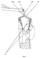
- Fig. 2
- Detail; Ruhezustand von Pilot mit Gurtzeug, Verbindungsgelenk zum Rotor, Koppelung und Pilotenaufhängung
- Fig. 3
- Detail; wie
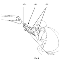
Fig. 2 jedoch unter Fliehkraftbelastung - Fig. 4
- Detail; wie
Fig. 3 mit nochmals gesteigerter Fliehkraftbelastung - Fig. 5
- Funktion Raffgewicht (Simulation der Steuerkräfte)
- Fig. 6
- Darstellung der Lage der Achsen bezogen auf den Körper des Piloten (Hochachse z, Längsachse x und Querachse y.)
- Fig. 1
- Overview of the centrifugal force simulator
- Fig. 2
- Detail; Hibernation of pilot with harness, connecting joint to the rotor, coupling and pilot suspension
- Fig. 3
- Detail; as
Fig. 2 but under centrifugal load - Fig. 4
- Detail; as
Fig. 3 with even increased centrifugal load - Fig. 5
- Raff weight function (simulation of the control forces)
- Fig. 6
- Representation of the position of the axes relative to the body of the pilot (vertical axis z, longitudinal axis x and transverse axis y.)
Der Fliehkraftsimulator besteht wie in
Die Auslegung von Drehzahl des Rotors (30) und Radius des Rotors (30) ist so gewählt, dass das Produkt aus Radius und Winkelgeschwindigkeit, die Fliehkraft, jenen Werten entspricht, die im Flug mit dem Gleitschirm erreicht werden. Der Radius des Rotors (30) ist dabei geringer als der Bahnradius im wirklichen Flug, dafür ist die Winkelgeschwindigkeit des Getriebemotors (20) größer. Dadurch wird eine kleinere Baugröße des Fliehkraftsimulators erreicht.The design of the speed of the rotor (30) and radius of the rotor (30) is chosen so that the product of radius and angular velocity, the centrifugal force, corresponds to those obtained in flight with the paraglider. The radius of the rotor (30) is less than the orbit radius in real flight, but the angular velocity of the geared motor (20) is greater. As a result, a smaller size of the centrifugal force simulator is achieved.
Der Fliehkraftsimulator ist so konzipiert, dass der Pilot in Abhängigkeit der Fliehkraft genau jene Lage im Raum einnimmt, die er auch während des Fluges einnimmt. Dies ist für die realistische Simulation von sehr großer Bedeutung, da die Fliehkräfte aufgeteilt in die drei Achsen gx, gy und gz , die entlang der Achsen x, y und z wirken (
Ein Gleitschirm kann auf zwei Weisen in eine Kurve gesteuert werden. Entweder durch Zug an den Steuerleinen (61), oder durch Verlagerung des Körperschwerpunktes nach einer Seite. Durch diese Verlagerung wandert eine der beiden Aufhängungspunkte (65) nach oben, der andere nach unten, der Gleitschirm bekommt eine asymmetrische Auftriebsverteilung und dreht dadurch in die Richtung in die der Körperschwerpunkt verlagert wird.A paraglider can be steered into a curve in two ways. Either by pulling on the control lines (61), or by shifting the center of gravity to one side. By this displacement, one of the two suspension points (65) moves upwards, the other down, the paraglider gets an asymmetric lift distribution and thereby rotates in the direction in which the center of gravity is shifted.
Die Pilotenaufhängung (60) ist durch das Verbindungsgelenk (40) mit dem Rotor (30) verbunden. Durch die untere Lagerung (40 X2) am Verbindungsgelenk (40) wird es dem Piloten ermöglicht, die im Flug übliche Gewichtsverlagerung am Fliehkraftsimulator anzuwenden. Dies bewirkt eine wesentliche Änderung der Aufteilung der Fliehkraftkomponenten gx, gy, und gz, die auf den Körper wirken. Daher ist dies bei der Simulation berücksichtigt. Die Resultierende aus den drei g-Komponenten bleibt dadurch unverändert.The pilot suspension (60) is connected to the rotor (30) by the connecting joint (40). The lower bearing (40 X2) on the connecting joint (40) allows the pilot to apply the usual in-flight weight transfer to the centrifugal force simulator. This causes a substantial change in the distribution of the centrifugal force components gx, gy, and gz, which act on the body. Therefore, this is taken into account in the simulation. The resultant of the three g-components remains unchanged.
Beim Einleiten einer Steilspirale schwenkt am Beginn der Einleitung der Pilotenkörper erst um die Längsachse x (flaches Drehen). Je hoher die g-Belastung umso stärker wird der Körper nach außen gedrückt. Dabei ist gemäß einer mathematischen Beziehung jeder g-Belastung ein eindeutiger Winkel zugeordnet. (60° bei 2 g, 90° würde einer unendlichen Fliehkraft entsprechen.)When initiating a spiral dive pivots at the beginning of the introduction of the pilot body only about the longitudinal axis x (flat turning). The higher the g-load the stronger the body is pushed outwards. In this case, according to a mathematical relationship, each g-load is assigned a unique angle. (60 ° at 2 g, 90 ° would correspond to an infinite centrifugal force.)
Diese Bewegung wird am Simulator durch die obere Lagerung (40 X1) am Verbindungsgelenk (40) realisiert.This movement is realized on the simulator by the upper bearing (40 X1) on the connecting joint (40).
Durch die gleitschirmbedingte Aerodynamik mit zunehmender g-Belastung, erfährt der Pilot auch eine Drehung um seine Hochachse z, das so genannte "auf die Nase kippen". Dadurch wandert die Blickrichtung des Piloten mit zunehmender g-Belastung nach unten. Der Schirm geht in den Spiralsturz über. Radiale Beschleunigungen auf der Kreisbahn wirken jetzt nicht mehr wie anfangs in x-Richtung wie bei der Beschleunigung eines Karussells, sondern zunehmend entlang der Querachse y.Due to the paraglider-related aerodynamics with increasing g-load, the pilot also experiences a rotation about its vertical axis z, the so-called "tipping on the nose". As a result, the direction of view of the pilot moves downwards with increasing g-load. The shade goes over into the spiral fall. Radial accelerations on the circular path no longer act as initially in the x-direction as in the acceleration of a carousel, but increasingly along the transverse axis y.
Diese Bewegung wird am Fliehkraftsimulator im Verbindungsgelenk (40) durch die Lagerung (40 Z) realisiert.This movement is realized on the centrifugal force simulator in the connecting joint (40) by the bearing (40 Z).
Das Zusammenspiel der beiden Auslenkungen des Piloten während der Beschleunigung auf seiner Bahn ist geringfügig abhängig von den Konstruktionsmerkmalen und Flugeigenschaften des Gleitschirmes. Anfänglich überwiegt die Rotation um die Längsachse x des Piloten, bei höheren g-Lasten überwiegt dann die Schwenkbewegung um die Hochachse z des Piloten (Blick nach unten). Grundsätzlich gilt aber, dass das Ausschwenken des Pilotenkörpers um die Längsachse x in der Lagerung (40 X1) immer kleiner ist als 90 °,da 90°einer g-Belastung von unendlich entsprechen würde. Im Gegensatz dazu kann die Drehung um die Hochachse z in der Lagerung (40Z) mehr als 90°betragen, der Pilot fliegt dann mit dem Körper in der Spiralbewegung bereits mit einer Rückwärtskomponente, was den Übergang in das Flugmanöver "SAT" bedeutet.The interaction of the two deflections of the pilot during the acceleration on its orbit is slightly dependent on the design features and flight characteristics of the paraglider. Initially, the rotation predominates around the longitudinal axis x of the pilot, at higher g loads, the pivotal movement about the vertical axis z of the pilot then predominates (view downwards). Basically, however, that the pivoting of the pilot body about the longitudinal axis x in the storage (40 X1) is always smaller than 90 °, since 90 ° would correspond to a g-load of infinity. In contrast, the rotation about the vertical axis z in the bearing (40Z) can be more than 90 °, the pilot then flies with the body in the spiral motion already with a backward component, which means the transition to the maneuver "SAT".
Um das Zusammenspiel der beiden Schwenkbewegungen um die Achsen (40 X1) und (40 Z) die der Pilot in der Spirale während seiner Beschleunigung vollführt am Fliehkraftsimulator zu realisieren, ist eine Koppelung (50) bestehend aus der Koppelungsstange (51) und der Koppelungsstange (52) zwischen Rotor (30) und Verbindungsgelenk (40) installiert.In order to realize the interaction of the two pivoting movements about the axes (40 X1) and (40 Z) which the pilot performs in the spiral during its acceleration at the centrifugal force simulator, a coupling (50) consisting of the coupling rod (51) and the coupling rod ( 52) between the rotor (30) and connecting joint (40) installed.
Die Koppelung bewirkt, dass der Pilotenkörper, der mit zunehmender Drehung durch die Fliehkraft nach außen schwenkt (40 X1), auch wie im Flug seine Blickrichtung nach unten schwenkt. Dabei beeinflusst eine Änderung der Länge der Koppelungsstange (51) und der Koppelungsstange (52) sowie der Winkel zwischen z-y Ebene des Piloten und der Koppelungsstange (52) das Zusammenspiel der beiden Drehbewegungen. Durch die mechanische Veränderung dieser Parameter (Winkel und Länge der Koppelungsstangen (51) und (52) kann der Fliehkraftsimulator auf das Verhalten unterschiedlicher Gleitschirmtypen abgestimmt werden.The coupling causes the pilot body, which pivots outward with increasing rotation by the centrifugal force (40 X1), also pivots his gaze downward in flight. In this case, a change in the length of the coupling rod (51) and the coupling rod (52) and the angle between z-y plane of the pilot and the coupling rod (52) affects the interaction of the two rotational movements. By mechanically changing these parameters (angle and length of the coupling rods (51) and (52) the centrifugal force simulator can be adapted to the behavior of different types of paraglider.
Die Koppelung der beiden Schwenkbewegungen um die x- und z-Achse des Piloten könnte auch durch eine elektromechanische Lösung mittels Stellmotoren und Regelungstechnik realisiert werden.The coupling of the two pivoting movements about the x- and z-axis of the pilot could also be realized by an electromechanical solution by means of servo motors and control technology.
Ein Gleitschirm verfügt über zwei so genannte "Bremsen" oder ,,Steuerleinen" (61) mit denen er gesteuert wird. Der "Steuerweg" ist das Maß in cm wie weit an der Steuerleine gezogen wird. Grundsätzlich ist der Bremskraftanstieg im geradeaus Flug beim Ziehen an den Steuerleinen (61) in etwa linear, jedoch geringfügig abhängig von den Konstruktionsmerkmalen des Gleitschirmes sowie von der Flächenbelastung (Gesamtgewicht bezogen auf die projizierte Tragfläche)A paraglider has two so-called "brakes" or "steering lines" (61) to control it.The "control path" is the measure in centimeters how far the control line is pulled in. Basically, the brake force increase is in straight flight while pulling on the control lines (61) approximately linear, but slightly depending on the design features of the paraglider as well as the surface load (total weight relative to the projected wing)
Dieser Bremskraftanstieg wird durch ein Raffgewicht realisiert, bei dem mehrere Gewichte (62) übereinander angebracht sind und jeweils das unterste Gewicht durch Zug so weit angehoben wird, bis es auf das nächste Gewicht trifft und dieses mitnimmt. Dadurch wird zwar je nach Anzahl der Gewichte ein stufenförmiger Bremskraftanstieg realisiert, der aber als quasilinear zu betrachten ist, da der menschliche Körper den stufenförmigen Anstieg der Belastung auf die Hand ohnehin schwer wahrnehmen kann.This braking force increase is realized by a Raffgewicht, in which a plurality of weights (62) are mounted one above the other and in each case the lowest weight is raised by train until it meets the next weight and this entrains. As a result, depending on the number of weights a stepped brake force increase is realized, but which is considered to be quasi-linear, since the human body can perceive the step-like increase in the load on the hand anyway.
Die Simulation des Bremskraftanstieges mit zunehmendem Steuerweg könnte auch durch eine elektromechanische Lösung mittels Stellmotoren und Regelungstechnik realisiert werden.The simulation of the braking force increase with increasing control path could also be realized by an electromechanical solution by means of servo motors and control technology.
Zusätzlich zum Bremskraftanstieg mit zunehmendem Steuerweg, nimmt die Bremskraft mit zunehmender g-Belastung zu.In addition to the brake force increase with increasing control travel, the braking force increases with increasing g load.
Durch die Verwendung von Gewichten (62) zur Simulation der Bremskraft wird ein Bremskraftanstieg mit zunehmender g-Belastung erreicht, da auf die Gewichte (62) die Selbe Fliehkraft wirkt, wie auf den Piloten. Dies wäre bei Verwendung einer Feder nicht der Fall.By using weights (62) to simulate the braking force, braking force increase is achieved with increasing g-load since the same centrifugal force acts on the weights (62) as on the pilots. This would not be the case when using a spring.
Die Simulation des Bremskraftanstieges mit zunehmender g-Belastung könnte auch durch eine elektromechanische Lösung mittels Stellmotoren und Regelungstechnik realisiert werden.The simulation of the brake force increase with increasing g-load could also be realized by an electromechanical solution using actuators and control technology.
Die Steuerleinen (61) laufen über Umlenkrollen (63), (64). An einer Umlenkrolle (64) ist ein Drehpotentiometer angebracht, welche das Steuersignal für einen Frequenzumformer liefert, der den Getriebemotor (20) und damit den Rotor (30) in Drehung versetzt. Ein Zug an der Steuerleine (61) bewirkt, dass der Rotor (30) des Fliehkraftsimulators beschleunigt und dadurch der Pilot in die simulierte Lage mit entsprechender g-Belastung gebracht wird. Dabei steigt die Bremskraft mit steigendem Bremsweg und steigender g-Last an.The control lines (61) pass over deflection rollers (63), (64). On a pulley (64) a rotary potentiometer is attached, which provides the control signal for a frequency converter, which sets the geared motor (20) and thus the rotor (30) in rotation. A train at the Control line (61) causes the rotor (30) of the centrifugal force simulator to be accelerated and thereby the pilot is brought into the simulated position with corresponding g load. The braking force increases with increasing braking distance and increasing g-load.
Der Fliehkraftsimulator ist in der Lage durch die oben angeführten Konstruktionsdetails die räumliche Lage des Piloten in Abhängigkeit von der Fliehkraft, dem realen Flug entsprechend, realistisch zu positionieren. Einzig der Radius und die Winkelgeschwindigkeit des Fliehkraftsimulators sind im Vergleich zum realen Flug verändert. Der Pilot vollführt am Fliehkraftsimulator auch keine reale Vertikalbewegung.The centrifugal force simulator is able by the above-mentioned design details the position of the pilot according to the centrifugal force, the real flight according to realistic position. Only the radius and the angular velocity of the centrifugal simulator are changed in comparison to the real flight. The pilot also does not perform any real vertical movement on the centrifugal force simulator.
Um dem Fliehkraftsimulator eine weitere reale Komponente zu geben, sieht der Pilot während des Trainings seine unmittelbare Umgebung nicht. Er hat eine Virtual Reality Brille (90) auf, die zwei kleine hochauflösende Monitore und eine entsprechende Optik enthält. Diese Virtual Reality Brille (90) ist mit Infrarot Sensoren ausgestattet, ein bereits im Handel erhältliches Produkt, womit dem Piloten eine virtuelle dreidimensionale Landschaft eingeblendet wird. Durch die reale Lage, die durch die konstruktiven Komponenten des Fliehkraftsimulators verwirklicht werden, blickt der Pilot nun wie im Flug im selben Winkel auf die Landschaft, wie im Flug. Der Empfänger der Virtual Reality Brille ist im Zentrum des Fliehkraftsimulators angeordnet. Der geringfügig engere Radius auf dem der Pilot am Fliehkraftsimulator rotiert ist für die 3-d Wahrnehmung seiner Landschaft unerheblich.To give the centrifugal simulator another real component, the pilot does not see his immediate environment during training. He has a Virtual Reality Glasses (90), which contains two small high-resolution monitors and a corresponding optics. These virtual reality glasses (90) are equipped with infrared sensors, an already commercially available product, giving the pilot a virtual three-dimensional landscape. Due to the real situation, which are realized by the structural components of the centrifugal force simulator, the pilot now looks like in flight at the same angle on the landscape, as in flight. The receiver of the Virtual Reality glasses is located in the center of the centrifugal simulator. The slightly narrower radius on which the pilot rotates on the centrifugal simulator is irrelevant for the 3-d perception of his landscape.
Die höhere Winkelgeschwindigkeit aufgrund der Bauweise des Fliehkraftsimulators (Pilotenrotation auf kleinerem Radius des Rotors (30) als im realen Flug) würde eine etwas höhere Rotation der virtuellen Landschaft als in Wirklichkeit ergeben. Dieser Unterschied zum realen Flug muss ausgeglichen werden.The higher angular velocity due to the design of the centrifugal force simulator (pilot rotation on a smaller radius of the rotor (30) than in real flight) would give a somewhat higher rotation of the virtual landscape than in reality. This difference to the real flight must be compensated.
Um die Winkelgeschwindigkeit des Fliehkraftsimulators an den entsprechenden virtuellen Eindruck anzugleichen wird der Empfängersensor des Virtual Reality Systems um die z-Achse in selber Drehrichtung wie der Rotor (30) versetzt jedoch langsamer, sodass die Winkelgeschwindigkeit zwischen Pilot und Koordinatensystem des Infrarotempfängers der realen Winkelgeschwindigkeit im Flug entspricht.However, to approximate the angular velocity of the centrifugal force simulator to the corresponding virtual impression, the receiver sensor of the virtual reality system is displaced about the z axis in the same direction as the rotor (30), so that the angular velocity between the pilot and the infrared receiver real angular velocity in flight equivalent.
Wesentlicher Unterschied zu PC-Flugsimulatoren, die ebenfalls mit solchen Virtual Reality Brillen betrieben werden können ist, dass nicht die virtuelle Landschaft durch ein elektronisches Signal gesteuert wird, sondern die Landschaft als Koordinatensystem eingeblendet wird und sich die Bewegung im Raum erst durch die reale Bewegung des Piloten am Fliehkraftsimulator ergibt.A major difference to PC flight simulators, which can also be operated with such virtual reality glasses is that not the virtual landscape is controlled by an electronic signal, but the landscape is displayed as a coordinate system and the movement in space only through the real movement of the Pilot on the centrifugal simulator results.
Claims (6)
Applications Claiming Priority (1)
| Application Number | Priority Date | Filing Date | Title |
|---|---|---|---|
| AT18862009A AT509122B1 (en) | 2009-11-26 | 2009-11-26 | FLYING POWER SIMULATOR FOR PARAGLIDERS |
Publications (1)
| Publication Number | Publication Date |
|---|---|
| EP2337005A1 true EP2337005A1 (en) | 2011-06-22 |
Family
ID=43880977
Family Applications (1)
| Application Number | Title | Priority Date | Filing Date |
|---|---|---|---|
| EP10190022A Withdrawn EP2337005A1 (en) | 2009-11-26 | 2010-11-04 | Simulator for centrifugal force for paragliding |
Country Status (2)
| Country | Link |
|---|---|
| EP (1) | EP2337005A1 (en) |
| AT (1) | AT509122B1 (en) |
Cited By (5)
| Publication number | Priority date | Publication date | Assignee | Title |
|---|---|---|---|---|
| GB2487369B (en) * | 2011-01-18 | 2013-05-01 | Maelstrom Virtual Productions Ltd | Parachute training simulators |
| RU2538996C2 (en) * | 2011-12-29 | 2015-01-10 | Федеральное государственное военное образовательное учреждение высшего профессионального образования "Военный учебно-научный центр Сухопутных войск Общевойсковая академия Вооруженных Сил Российской Федерации" | Simulator of paratrooper |
| KR20160001184A (en) * | 2014-06-26 | 2016-01-06 | 주식회사 도담시스템스 | Simulation system for paragliding |
| RU2645516C2 (en) * | 2016-05-16 | 2018-02-21 | Федеральное государственное казенное военное образовательное учреждение высшего профессионального образования Рязанское высшее воздушно-десантное командное училище (военный институт) имени генерала армии В.Ф. Маргелова МО РФ | Dynamic simulator for use of parachute systems such as “flying wing” |
| US10082439B1 (en) * | 2016-09-16 | 2018-09-25 | Rockwell Collins, Inc. | Event depiction on center of gravity curve |
Citations (6)
| Publication number | Priority date | Publication date | Assignee | Title |
|---|---|---|---|---|
| JPH08182788A (en) * | 1994-12-28 | 1996-07-16 | Ishikawajima Harima Heavy Ind Co Ltd | Skidiving and parachuting training simulator |
| JPH08244690A (en) * | 1995-03-09 | 1996-09-24 | Ishikawajima Harima Heavy Ind Co Ltd | Simulator for parachute maneuvering training |
| JPH08244691A (en) * | 1995-03-09 | 1996-09-24 | Ishikawajima Harima Heavy Ind Co Ltd | Simulator for parachute manufacturing training |
| WO2002076829A1 (en) * | 2001-03-22 | 2002-10-03 | Sung Taee Lee | Skydiving simulator and skydiving training process using the same |
| DE102006015344A1 (en) * | 2006-04-03 | 2007-10-04 | Rüger, Ulrich, Dipl.-Ing. | Simulator for e.g. parachute, has control unit to generate control information for actuator, where rope impact takes place such that requirement to generate information of actuator is in connection with impact path and actuator distance |
| BRPI0700526A (en) | 2007-02-23 | 2008-10-14 | Hans Heinrich Vogt | paragliding flight simulator |
Family Cites Families (2)
| Publication number | Priority date | Publication date | Assignee | Title |
|---|---|---|---|---|
| SU355829A1 (en) * | 1970-11-12 | 1980-06-15 | Nevskij Yu B | Device for investigating effect of overloads on man rotating on centrifuge |
| JPH07334071A (en) * | 1994-06-08 | 1995-12-22 | Shimadzu Corp | Centrifugal force generator and method for determining arm shape of the device |
-
2009
- 2009-11-26 AT AT18862009A patent/AT509122B1/en not_active IP Right Cessation
-
2010
- 2010-11-04 EP EP10190022A patent/EP2337005A1/en not_active Withdrawn
Patent Citations (6)
| Publication number | Priority date | Publication date | Assignee | Title |
|---|---|---|---|---|
| JPH08182788A (en) * | 1994-12-28 | 1996-07-16 | Ishikawajima Harima Heavy Ind Co Ltd | Skidiving and parachuting training simulator |
| JPH08244690A (en) * | 1995-03-09 | 1996-09-24 | Ishikawajima Harima Heavy Ind Co Ltd | Simulator for parachute maneuvering training |
| JPH08244691A (en) * | 1995-03-09 | 1996-09-24 | Ishikawajima Harima Heavy Ind Co Ltd | Simulator for parachute manufacturing training |
| WO2002076829A1 (en) * | 2001-03-22 | 2002-10-03 | Sung Taee Lee | Skydiving simulator and skydiving training process using the same |
| DE102006015344A1 (en) * | 2006-04-03 | 2007-10-04 | Rüger, Ulrich, Dipl.-Ing. | Simulator for e.g. parachute, has control unit to generate control information for actuator, where rope impact takes place such that requirement to generate information of actuator is in connection with impact path and actuator distance |
| BRPI0700526A (en) | 2007-02-23 | 2008-10-14 | Hans Heinrich Vogt | paragliding flight simulator |
Cited By (5)
| Publication number | Priority date | Publication date | Assignee | Title |
|---|---|---|---|---|
| GB2487369B (en) * | 2011-01-18 | 2013-05-01 | Maelstrom Virtual Productions Ltd | Parachute training simulators |
| RU2538996C2 (en) * | 2011-12-29 | 2015-01-10 | Федеральное государственное военное образовательное учреждение высшего профессионального образования "Военный учебно-научный центр Сухопутных войск Общевойсковая академия Вооруженных Сил Российской Федерации" | Simulator of paratrooper |
| KR20160001184A (en) * | 2014-06-26 | 2016-01-06 | 주식회사 도담시스템스 | Simulation system for paragliding |
| RU2645516C2 (en) * | 2016-05-16 | 2018-02-21 | Федеральное государственное казенное военное образовательное учреждение высшего профессионального образования Рязанское высшее воздушно-десантное командное училище (военный институт) имени генерала армии В.Ф. Маргелова МО РФ | Dynamic simulator for use of parachute systems such as “flying wing” |
| US10082439B1 (en) * | 2016-09-16 | 2018-09-25 | Rockwell Collins, Inc. | Event depiction on center of gravity curve |
Also Published As
| Publication number | Publication date |
|---|---|
| AT509122A1 (en) | 2011-06-15 |
| AT509122B1 (en) | 2012-01-15 |
Similar Documents
| Publication | Publication Date | Title |
|---|---|---|
| EP2715702B1 (en) | Device for spatially moving persons | |
| DE102009019628B4 (en) | Air rescue simulator | |
| EP2612311B1 (en) | Apparatus and method for operating a flight simulator with a special impression of reality | |
| DE69910344T2 (en) | Cockpit display with three-dimensional trajectory deviation symbols | |
| DE102012023925A1 (en) | Method and apparatus for combined simulation and control of remotely controlled vehicles with a user-friendly projection system | |
| DE69628410T2 (en) | IMPROVED FLIGHT SIMULATOR | |
| AT509122B1 (en) | FLYING POWER SIMULATOR FOR PARAGLIDERS | |
| EP2235712A2 (en) | Method for simulating flight statuses of a vertical take-off and/or vertical landing-capable aircraft | |
| WO2014075655A2 (en) | Method and device for the combined simulation and control of remote-controlled vehicles | |
| EP3528232A1 (en) | Training simulator for an aerial vehicle | |
| DE10140676B4 (en) | Web guiding systems for a paraglider or paraglider and trajectory planning means for planning the deployment of at least one parachute or paraglider and methods for carrying out the web guidance and planning | |
| DE202015104591U1 (en) | Helicopter with multiple rotors and variable pitch | |
| DE102012106233A1 (en) | Method for representing oscillating motion of oscillation capable load, involves detecting oscillation deflection of oscillating motion of oscillation capable load with respect to vertical axis of support system | |
| DE202012011693U1 (en) | Device for the combined simulation and control of remote-controlled vehicles with a user-friendly projection system | |
| EP3175436B1 (en) | Apparatus for spatial movement of at least one person | |
| DE4138252A1 (en) | Device using centrifugal force for subjective simulation of forces - is used to influence movement of body | |
| DE4010375C2 (en) | ||
| DE3644899A1 (en) | Aircraft | |
| Groen et al. | Motion fidelity during a simulated takeoff | |
| DE102011105155B4 (en) | Apparatus and method for dynamically adjusting an orientation of an aircraft seat | |
| DE879964C (en) | Glider pre-training apparatus | |
| Groen et al. | Pilot's Perception and Control Behavior During Simulated Take Off | |
| DE19640730A1 (en) | Flight simulator for pilot training | |
| TRAINING | S LABORATORY | |
| DE202012011015U1 (en) | Device for the combined simulation and control of remotely controlled vehicles |
Legal Events
| Date | Code | Title | Description |
|---|---|---|---|
| PUAI | Public reference made under article 153(3) epc to a published international application that has entered the european phase |
Free format text: ORIGINAL CODE: 0009012 |
|
| AK | Designated contracting states |
Kind code of ref document: A1 Designated state(s): AL AT BE BG CH CY CZ DE DK EE ES FI FR GB GR HR HU IE IS IT LI LT LU LV MC MK MT NL NO PL PT RO RS SE SI SK SM TR |
|
| AX | Request for extension of the european patent |
Extension state: BA ME |
|
| 17P | Request for examination filed |
Effective date: 20111210 |
|
| GRAP | Despatch of communication of intention to grant a patent |
Free format text: ORIGINAL CODE: EPIDOSNIGR1 |
|
| INTG | Intention to grant announced |
Effective date: 20170127 |
|
| STAA | Information on the status of an ep patent application or granted ep patent |
Free format text: STATUS: THE APPLICATION IS DEEMED TO BE WITHDRAWN |
|
| 18D | Application deemed to be withdrawn |
Effective date: 20170607 |