EP2280239A1 - Illumination device for lighting a monitored area - Google Patents
Illumination device for lighting a monitored area Download PDFInfo
- Publication number
- EP2280239A1 EP2280239A1 EP09166515A EP09166515A EP2280239A1 EP 2280239 A1 EP2280239 A1 EP 2280239A1 EP 09166515 A EP09166515 A EP 09166515A EP 09166515 A EP09166515 A EP 09166515A EP 2280239 A1 EP2280239 A1 EP 2280239A1
- Authority
- EP
- European Patent Office
- Prior art keywords
- illumination
- axis
- field
- lenses
- lighting device
- Prior art date
- Legal status (The legal status is an assumption and is not a legal conclusion. Google has not performed a legal analysis and makes no representation as to the accuracy of the status listed.)
- Granted
Links
Images


Classifications
-
- G—PHYSICS
- G01—MEASURING; TESTING
- G01B—MEASURING LENGTH, THICKNESS OR SIMILAR LINEAR DIMENSIONS; MEASURING ANGLES; MEASURING AREAS; MEASURING IRREGULARITIES OF SURFACES OR CONTOURS
- G01B11/00—Measuring arrangements characterised by the use of optical techniques
- G01B11/24—Measuring arrangements characterised by the use of optical techniques for measuring contours or curvatures
- G01B11/25—Measuring arrangements characterised by the use of optical techniques for measuring contours or curvatures by projecting a pattern, e.g. one or more lines, moiré fringes on the object
-
- F—MECHANICAL ENGINEERING; LIGHTING; HEATING; WEAPONS; BLASTING
- F16—ENGINEERING ELEMENTS AND UNITS; GENERAL MEASURES FOR PRODUCING AND MAINTAINING EFFECTIVE FUNCTIONING OF MACHINES OR INSTALLATIONS; THERMAL INSULATION IN GENERAL
- F16P—SAFETY DEVICES IN GENERAL; SAFETY DEVICES FOR PRESSES
- F16P3/00—Safety devices acting in conjunction with the control or operation of a machine; Control arrangements requiring the simultaneous use of two or more parts of the body
- F16P3/12—Safety devices acting in conjunction with the control or operation of a machine; Control arrangements requiring the simultaneous use of two or more parts of the body with means, e.g. feelers, which in case of the presence of a body part of a person in or near the danger zone influence the control or operation of the machine
- F16P3/14—Safety devices acting in conjunction with the control or operation of a machine; Control arrangements requiring the simultaneous use of two or more parts of the body with means, e.g. feelers, which in case of the presence of a body part of a person in or near the danger zone influence the control or operation of the machine the means being photocells or other devices sensitive without mechanical contact
- F16P3/142—Safety devices acting in conjunction with the control or operation of a machine; Control arrangements requiring the simultaneous use of two or more parts of the body with means, e.g. feelers, which in case of the presence of a body part of a person in or near the danger zone influence the control or operation of the machine the means being photocells or other devices sensitive without mechanical contact using image capturing devices
-
- F—MECHANICAL ENGINEERING; LIGHTING; HEATING; WEAPONS; BLASTING
- F16—ENGINEERING ELEMENTS AND UNITS; GENERAL MEASURES FOR PRODUCING AND MAINTAINING EFFECTIVE FUNCTIONING OF MACHINES OR INSTALLATIONS; THERMAL INSULATION IN GENERAL
- F16P—SAFETY DEVICES IN GENERAL; SAFETY DEVICES FOR PRESSES
- F16P3/00—Safety devices acting in conjunction with the control or operation of a machine; Control arrangements requiring the simultaneous use of two or more parts of the body
- F16P3/12—Safety devices acting in conjunction with the control or operation of a machine; Control arrangements requiring the simultaneous use of two or more parts of the body with means, e.g. feelers, which in case of the presence of a body part of a person in or near the danger zone influence the control or operation of the machine
- F16P3/14—Safety devices acting in conjunction with the control or operation of a machine; Control arrangements requiring the simultaneous use of two or more parts of the body with means, e.g. feelers, which in case of the presence of a body part of a person in or near the danger zone influence the control or operation of the machine the means being photocells or other devices sensitive without mechanical contact
- F16P3/144—Safety devices acting in conjunction with the control or operation of a machine; Control arrangements requiring the simultaneous use of two or more parts of the body with means, e.g. feelers, which in case of the presence of a body part of a person in or near the danger zone influence the control or operation of the machine the means being photocells or other devices sensitive without mechanical contact using light grids
-
- G—PHYSICS
- G02—OPTICS
- G02B—OPTICAL ELEMENTS, SYSTEMS OR APPARATUS
- G02B3/00—Simple or compound lenses
- G02B3/0006—Arrays
- G02B3/0037—Arrays characterized by the distribution or form of lenses
- G02B3/0062—Stacked lens arrays, i.e. refractive surfaces arranged in at least two planes, without structurally separate optical elements in-between
- G02B3/0068—Stacked lens arrays, i.e. refractive surfaces arranged in at least two planes, without structurally separate optical elements in-between arranged in a single integral body or plate, e.g. laminates or hybrid structures with other optical elements
Definitions
- the invention relates to a lighting apparatus and a method for illuminating a surveillance area according to the preamble of claim 1 and 12, respectively.
- a typical safety application is the protection of a dangerous machine, such as a press or a robot, where protection is provided when a body part is engaged in a hazardous area around the machine. Depending on the situation, this can be the shutdown of the machine or the move to a safe position.
- Three-dimensional monitoring procedures based on stereoscopy are particularly demanding.
- images of the scenery are obtained from slightly different perspectives.
- the same structures are identified and calculated from the disparity and the optical parameters of the camera system by means of triangulation distances and thus a three-dimensional image or a depth map.
- Stereoscopic camera systems offer the advantage compared to conventional safety-related sensors such as scanners and light grids to determine area-wide depth information from a two-dimensionally recorded observation scene.
- safety areas can be defined more variably and more accurately and more and more accurate classes of permitted object movements can be distinguished, for example, movements of the robot itself or movements of a body part on the dangerous machine in a different depth level, which in itself completely harmless is, but can not be differentiated from a two-dimensional camera.
- Active stereo measurement systems therefore use, in addition to the receiving system, ie essentially two calibrated cameras, a lighting unit whose function is to illuminate the observed scene with structured light and thus to generate features through the numerous light-dark transitions in the images the stereo algorithm can extract reliable and dense distance data from the scenery.
- Such patterns may also be self-dissimilar, that is to say that for the present monitors there are in the first place no regions which are symmetrical relative to displacements.
- lighting units with projection techniques similar to a slide projector or based on diffractive optical elements (DOE) are proposed as pattern generators.
- Light losses in the projector, for example in a slide are accepted.
- the required high light output provide halogen lamps, which are relatively short-lived.
- Semiconductor light sources have a long service life and simplify the monitoring task compared to conventional broadband lamps, because the defined narrow frequency spectrum of their useful light can be distinguished from ambient light by optical filters.
- high-power LEDs or high-power lasers can be used.
- Laser bars cost-effectively deliver the required light output.
- their illumination field and their intensity distribution with known optics does not meet the requirements for a uniform illumination of a surveillance area. Therefore, laser bars are not used in conventional projectors, but projectors are operated with conventional lamps or LEDs.
- the coherence of a laser light source is even undesirable because it leads to parasitic effects in the projected image.
- an opto-electronic sensor for determining the distance of an object with a lighting unit which has a laser stack and a DOE in order to generate a regular dot pattern.
- no measures are disclosed to form the illumination field of the laser stack.
- the illumination line of a camera-based code reader is generated by a plurality of LEDs arranged in a row.
- each LED is associated with a lens which, via an offset relative to the optical axis of the LED, a variation of the pitch or wedge surfaces, achieves a desired superimposition of the individual LEDs.
- the illumination line is unsuitable for planar monitoring tasks.
- the US 5,139,609 is an example of the use of laser bar micro-lens arrays, used here to pump a solid-state laser.
- Such conventional microlens fields do not provide rectangular illumination fields that could be used to illuminate a camera sensor.
- the invention is based on the basic idea of ensuring the most homogeneous possible illumination of the monitoring area. Then the available brightness dynamics of the sensor can be used completely to compensate for remission dynamics or external light dynamics, and only little light is lost through internal losses. For this purpose, the light of the light sources is redistributed defined, so as to obtain a lighting field of the desired shape and intensity distribution.
- the desired intensity distribution is usually homogeneous. In some situations, it may be beneficial to deviate from this purpose, for example, by increasing the light output at the edges to compensate for corresponding edge losses in the camera.
- the illumination field is formed in two steps, wherein initially in the first axis a line and then by the tilting or deflection of an illumination field respectively desired intensity distribution is formed.
- the invention has the advantage that very inexpensive and powerful light sources can be used. It is a compact design of the lighting device possible. In the illumination field a very good homogeneity with low light losses and without affecting the coherence is achieved. The light distribution can also deliberately deviate from a homogeneous distribution and is so very flexible.
- the microlens array has a dual optical effect, namely intensity redistribution in the first axis and light distribution on the illumination field in the second axis. These two effects can also be realized in two separate optical elements.
- the microlens array is then planar and provides a line of illumination of the desired intensity distribution.
- An upstream or downstream prism field that is, for example, an array of wedges of an optically transparent material, such as glass, draws the line to the illumination field. This has manufacturing advantages, but also brings a certain adjustment effort and additional interface losses with it.
- both embodiments can also be mixed by assigning a prism field to a non-planar microlens field and thus adding the deflections in the second axis.
- the light sources arranged in a line are preferably the emitters of a laser bar whose slow axis coincides with the first axis and whose fast axis coincides with the second axis, wherein the laser bar has, in particular, internal collimating optics for the collimation of the emitted light bundles in the second axis. If more than one line of light sources is provided, then correspondingly a plurality of laser bars are used, which can also be stacked to form a laser stack. This achieves even higher light outputs.
- laser bars with a large number of 10 or more emitter surfaces. They are narrow band and have high output power. In addition, the laser cost per watt output power is very low. Laser bars are thus more powerful and, above all, significantly cheaper than for single lasers (single emitters). They have a high-beam axis (fast axis) and a slow-axis axis. The laser bar is aligned so that the first axis coincides with the slow axis. The first axis is thus at the same time the Kollimtechnikslegi the lenses of the microlens array and the direction of extension of the illumination line. In addition, the laser bar is aligned so that the second axis coincides with the fast axis.
- the resulting illumination field is accordingly spanned in the direction of the first and the second axis.
- the third vertical axis is the transmission direction of the illumination device or its optical axis.
- the lenses are preferably similar to each other and in particular formed as spherical cylindrical lenses, which are aligned parallel to each other in their longitudinal axes at least up to the tilt angle, wherein the tilt angle has no share in the first axis.
- the tilt takes place only in the by the second axis and the optical axis spanned plane.
- a slight deviation from the parallelism is conceivable.
- an additional tilt in the first axis can compensate for the parallel displacement of the line segments generated by the individual light sources.
- due to the design such tilting is only possible to a very limited extent since otherwise the cylindrical lenses would have to physically overlap.
- the tilt angle is preferably constant, in particular 0.1 ° to 1 °, or the optical deflection elements are formed as wedges whose wedge angle differs between two adjacent deflection elements by the constant tilt angle. It is again emphasized that the tilt angle is defined as the relative tilt angle between adjacent microstructure elements, not as an absolute tilt angle. In a different terminology absolute tilt angle, the absolute tilt angle of microstructure element to microstructure element would increase by the same constant amount, the absolute tilt angle thus form a linear function. Either the microlens field itself or the associated prism field ensures through this uniform tilting for a correspondingly uniform winding of the illumination line and thus homogeneity of the illumination field. A particularly suitable tilt angle is 0.5 °.
- Deviations from constant tilt angles ensure a targeted deviation from homogeneous illumination in the second axis. If, for example, smaller tilt angles are selected at the edge of the microlens field or the prism field than in the middle region, this leads to an increase in intensity at the edges of the illumination field in the second axis.
- the tilt angles are advantageously set such that the illumination field has a desired aspect ratio, in particular of 4: 3 or 16: 9.
- the tilt angles directly affect the extent of the illumination field in the second axis.
- This allows setting an aspect ratio.
- This preferably corresponds to the aspect ratio of the image sensor of the camera in order to optimally utilize the full light energy as well as the full number of pixels.
- other aspect ratios are achievable if, for example, a used image sensor chip has a different aspect ratio than 4: 3 or 16: 9. It is also possible, by relative tilting of the illumination device with respect to the image sensor, to reach 90 ° so that always the longer side is the one with the better homogeneity, be it the first axis or the second axis.
- the expansion is predetermined by the number and pitch of the individual light sources and of the microstructure elements.
- the expansion in the first axis can furthermore be influenced by the curvature properties or focal lengths of the individual lenses of the microstructure element.
- an imaging element which images the illumination field in a common focal plane behind the light sources.
- the distance of the focal plane amounts to a few millimeters or centimeters, preferably between 0.1 and 20 cm or even more preferably between 0.5 and 3 cm.
- the imaging element may be formed as an imaging lens in the form of a conventional convex lens or cylindrical lens.
- a pattern generation element is provided in the illumination device, which is arranged in the beam path such that the illumination field falls onto the pattern generation element, thus illuminating the surveillance area in a substantially rectangular partial area with a structured illumination pattern.
- Such patterns increase contrast, enable light-sectioning or active stereoscopy with a lighting pattern that creates regular or locally self-dissimilar lighting structures in the surveillance area.
- the pattern generating element has an optical phase element with bumps adapted to generate local phase differences between adjacent light portions striking the phase element, in particular the bumps being irregular and provided everywhere in the area in which the illumination field falls, thus to completely illuminate the rectangular portion of the surveillance area with a self-similar illumination pattern.
- a phase element has the advantage over a slide or a mask in that the light is only redistributed and not absorbed, thus more light power is available in the monitoring area and no thermal problems arise in the lighting device. The redistribution effect of the phase element is based on the coherence of the incident light. Therefore, the lighting device according to the invention is superior to conventional fiber couplers or homogenizers, including honeycomb condensers, which could produce no or only a significantly less structured illumination pattern with a phase element.
- the lighting device is part of a security camera, in particular a 3D stereo security camera, which has a security output and an evaluation unit which is designed to detect impermissible interventions in the surveillance area and then output a shutdown signal via the security output.
- a security camera in particular a 3D stereo security camera
- the improved illumination supports the reliable detection of impermissible events, allows longer ranges and increases the immunity of the security camera.
- the evaluation unit is preferably designed for the application of a stereo algorithm in which mutually associated subareas of the images recorded by the two cameras of the stereo camera are recognized and whose distance is calculated on the basis of the disparity.
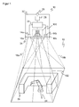
- FIG. 1 shows in a schematic three-dimensional representation of the general structure of a 3D security camera according to the invention 10 according to the stereoscopic principle, which is used for safety monitoring of a room area 12.
- Two camera modules are mounted in a known fixed distance from each other and each take pictures of the space area 12.
- an image sensor 14a, 14b is provided, usually a matrix-shaped recording chip, which receives a rectangular pixel image, for example a CCD or a CMOS sensor.
- an objective with imaging optics which are shown as lenses 16a, 16b and can be realized in practice as any known imaging objective.
- the viewing angle of these optics is in FIG. 1 represented by dashed lines, each forming a viewing pyramid 18a, 18b.
- a lighting unit 100 is shown, this spatial arrangement is to be understood only as an example and the lighting unit may also be arranged asymmetrically or even outside the security camera 3D.
- the illumination unit 100 according to the invention generates a structured illumination pattern, homogeneous illumination or illumination with a different desired intensity distribution in an illumination area 102 in the spatial area 12, and will be described below in various embodiments in connection with FIGS FIGS. 2 to 10 explained in more detail.
- a controller 22 is connected to the two image sensors 14a, 14b and the illumination unit 100.
- the controller 22 controls the lighting unit 100 and, on the other hand, receives image data of the image sensors 14a, 14b. From these image data the controller 22 computes three-dimensional image data (range image, depth map) of the spatial region 12 by means of stereoscopic disparity estimation.
- the illumination pattern provides good contrast and, especially if it is self-similar, a unique structure of each pixel in the illuminated spatial region 12. The most important The aspect of self-dissimilarity is the at least local, better global lack of translational symmetries, so that no apparent shifts of picture elements in the images respectively taken from different perspectives are recognized due to the same illumination pattern elements that would cause errors in the disparity estimation.
- the space area 12 monitored by the 3D security camera 10 may contain known and unexpected objects. This may be, for example, a robot arm 24, a machine, an operator and others.
- the room area 12 provides access to a source of danger, be it because it is an access area or because a dangerous machine 24 is in the room area 12 itself.
- one or more virtual protection and warning fields 26 may be configured. They form a virtual fence around the dangerous machine 24. Due to the three-dimensional evaluation, it is possible to define protection and warning fields 26 three-dimensionally, so that a great flexibility arises.
- the controller 22 evaluates the three-dimensional image data for impermissible interventions.
- the evaluation rules may stipulate that no object may exist in protected fields at all. More flexible evaluation rules provide differentiation between allowed and non-permitted objects, such as trajectories, patterns or contours, speeds or general workflows that are both learned in advance as well as evaluated on the basis of assessments, heuristics or classifications during operation.
- a warning or shutdown device 28 which in turn can be integrated in the controller 22, issues a warning or safeguards the source of danger, for example the robot arm 24 is stopped.
- Safety-related signals in particular the shutdown signal, are output via a safety output 30 (OSSD, Output Signal Switching Device). It depends on the application, whether a warning is sufficient, or it is a two-stage hedge provided in the first warned and only with continued object engagement or even deeper penetration is switched off. Instead of a shutdown, the appropriate response may also be the immediate transfer to a safe parking position.
- the 3D security camera 10 is surrounded by a housing 32 and protected. Through a front screen 34, light can pass in and out of the space area 12.
- the 3D safety camera 10 is designed to be fail-safe. Among other things, this means that the 3D security camera 10 can test itself, even in cycles below the required response time, in particular also detects defects of the illumination unit 100 and thus ensures that the illumination pattern is available in an expected minimum intensity, and that the security output 30 and the warning or shutdown 26 safe, for example, two channels are designed. Likewise, the controller 22 is self-confident, thus evaluating two-channel or uses algorithms that can check themselves. Such regulations are standardized for general non-contact protective devices in EN 61496-1 or IEC 61496 as well as in DIN EN ISO 13849 and EN 61508. A corresponding standard for security cameras is in preparation.
- the invention is explained using the example of the 3D security camera 10.
- the lighting unit 100 can also be used for other cameras, other sensors or in other applications.
- FIG. 2 shows a simplified plan view of a lighting unit 100 according to the invention.
- a laser bar 104 has a plurality of individual emitters 106, which are arranged in a row.
- other semiconductor light sources for example LEDs or single-emitter lasers, can in principle also be used; the optics described below then work in the same way.
- a laser bar 104 is a particularly inexpensive, high-performance source of coherent light.
- the slow axis of the single emitter 106 forms an in FIG. 2 X axis called first axis.
- Emissive light beams 108 are collimated in the X-axis by a microlens array 110.
- the intensity distribution 114 of the individual light bundles 108 as well as the superimposition 116 of all the individual intensity distributions 114 are shown above the resulting illumination line 112.
- the gaussian drop of the intensity distributions 114 as well as the collimation is exaggerated. In practice, the individual intensity distributions 114 are wider and thus themselves line-shaped.
- the fast axis of the laser bar 104 is in FIG. 2 perpendicular to the paper plane.
- this second axis referred to as the Y-axis
- the beams 108 of the individual emitters 106 are collimated by an internal optics (not shown).
- the thickness of the illumination line 112 is ultimately adjusted.
- FIG. 2 how a plurality of illumination lines are superimposed by a microlens array 110 in a first step to form a homogeneous common illumination line.
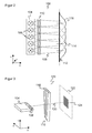
- FIG. 3 shows a three-dimensional representation of the illumination unit 100, in which case as in the following like reference numerals designate the same features.
- the individual lenses 118 of the microlens array 110 are elongated spherical cylindrical lenses whose optically effective curvature provides for collimation in the slow axis.
- the lenses 118 are aligned substantially parallel to one another, but at the same time tilted relative to one another in the plane spanned by the Y axis and the Z axis coinciding with the optical axis 120 of the illumination unit 100.
- This tilting increases, as viewed from the laser bar 104, from left to right, for example, with tiltings of -1 °, -0.5 °, 0 °, 0.5 ° and 1 ° for the five illustrated lenses 118.
- the tilt angle of two adjacent lenses 118 is thus 0.5 °.
- Other, even irregularly distributed and not monotonically increasing or decreasing tilt angle are conceivable.
- a rectangular illumination field 124 then forms on a fictitious projection plane 122 shortly behind the illumination unit 100.
- the extent of the opening angle of the individual emitter 106 in the X direction, the slow axis, and the curvature or focal length of the lenses 118 is determined. This determines the length of the lighting lines.
- the expansion results from the tilt angles.
- Each lens 118 deflects an associated line of illumination of a single emitter 106 in the Y direction. From the lighting lines thus arranged one above the other, the illumination field 124 is composed.
- the lens properties of the microlens array 110 thus cause the beam shaping of the individual emitter 106 to a line of illumination 112, while the tilting this illumination line 112 mitigates to the flat, rectangular illumination field 124.
- FIG. 4 shows an embodiment in which the two optical effects are separated in reality and are generated by their own optical elements.
- the microlens array 110a is planar here and thus does not deflect the illumination lines in the Y direction. This occurs only in a pre- or subordinate prism or keel field 126. It consists for example of mutually tilted wedges 128 made of glass or other optical material. Each wedge 128 has a different wedge angle analogous to the tilt angles in the microlens array 110 of FIG FIG. 3 on. Also conceivable is a combination in which a microlens array 110 with tilted lenses 118 is combined with the prism field 126 and thus the deflection in the Y direction is added.
- a homogeneous illumination field 124 is created.
- suitable choice of the individual tilt angles and by supplementing the shape of the lenses 118 with aspherical portions it is possible to perform a targeted redistribution of the light within the illumination field 124 ,
- the vignetting of the receiving optics 116 or losses due to grazing incidence of the light can be partially compensated.
- This homogeneous illumination field 124 is used to project a pattern in the space area 12.
- This homogeneous illumination field 124 is used to project a pattern in the space area 12.
- the microlens array 110 with tilted lenses 118 is shown here, another embodiment having a planar microlens array 118 and a prism array 126 operates quite analogously.
- An imaging lens 130 which may be embodied as a convex cylindrical lens, collects the individually differently deflected ray bundles 108 and images them off in a focal plane a few centimeters behind the laser bar 104. In the rear focal plane of the imaging lens 130 thus the homogeneous light distribution is generated.
- the homogeneous illumination field 124 is projected through a phase element 132 into the spatial region 12.
- the phase element 132 is for example a phase plate with bumps formed over the area in which it is illuminated by the illumination field 124.
- a self-similar, structured illumination pattern 134 is created in the spatial region 12. In order to generate these interference effects, the coherence of the light of the laser bar 104 should be preserved.
- FIGS. 6 to 8 show in three-dimensional views from different perspectives a representation of the microlens array 110.
- the individual lenses 118 are shown simplified without curvature in order to better recognize the tilt angle.
- At the back further optical elements, such as the imaging lens 130, can be directly connected to this block in order to at least largely avoid an air gap and nevertheless to set the desired distance.
- the Figures 9 and 10 show simulation results of the illumination line 112 and the illumination field 124, respectively FIG. 9 Accordingly, the tilt angle is set to 0 °, so that only one illumination line 112 is formed. In FIG. 10 On the other hand, a finite tilt angle is set.
- the illumination lines belonging to a respective single emitter 106 are offset from one another in the Y direction and together form a rectangular illumination field 124 of high homogeneity. About the amount of tilt angle, the aspect ratios are changeable.
- the individual emitters 106 have a small distance to one another, however, the individual illumination lines that make up the illumination field 124 are slightly shifted from one another.
- the illumination field 124 thereby becomes slightly diamond-shaped. It is conceivable to make a compensating shear, for example by additional tilting of the lenses 118 in the plane spanned by the X-axis and Y-axis, or by another prism field. Practically this is only necessary in particularly demanding applications, since the rhombic effect is often very small and the shear entails the risk of additional optical disturbances or losses.
- the invention enables the defined redistribution of the light of a laser bar 104 into a homogeneous, rectangular light field 124 of variably adjustable aspect ratios with the aid of simple microstructure elements.
- laser bars 104 can be used as the illumination source of a lighting device 100 for a camera sensor 10.
- the illuminated field of a laser bar 104 is adapted to the projection field of a laser illumination.
- the losses are kept low and achieved a high illumination homogeneity.
- the microstructure elements 110, 110a and 126 are very cost-effective and simple to manufacture, since a casting mold can be produced once and the microstructure element 110, 110a and 126 can be molded from it in any desired number.
Abstract
Description
Die Erfindung betrifft eine Beleuchtungsvorrichtung und ein Verfahren zur Beleuchtung eines Überwachungsbereichs nach dem Oberbegriff von Anspruch1 beziehungsweise 12.The invention relates to a lighting apparatus and a method for illuminating a surveillance area according to the preamble of
Seit langem werden Kameras zur Überwachung eingesetzt und finden zunehmend auch Anwendung in der Sicherheitstechnik. Eine typische sicherheitstechnische Anwendung ist die Absicherung einer gefährlichen Maschine, wie etwa einer Presse oder eines Roboters, wo bei Eingriff eines Körperteils in einen Gefahrenbereich um die Maschine herum eine Absicherung erfolgt. Dies kann je nach Situation die Abschaltung der Maschine oder das Verbringen in eine sichere Position sein.Cameras have long been used for surveillance and are increasingly being used in security technology. A typical safety application is the protection of a dangerous machine, such as a press or a robot, where protection is provided when a body part is engaged in a hazardous area around the machine. Depending on the situation, this can be the shutdown of the machine or the move to a safe position.
Besonders hohe Anforderungen stellen dreidimensionale Überwachungsverfahren, die auf Stereoskopie beruhen. Dabei werden Bilder der Szenerie aus leicht unterschiedlichen Perspektiven gewonnen. In den überlappenden Bildbereichen werden gleiche Strukturen identifiziert und aus der Disparität und den optischen Parametern des Kamerasystems mittels Triangulation Entfernungen und somit ein dreidimensionales Bild beziehungsweise eine Tiefenkarte berechnet.Three-dimensional monitoring procedures based on stereoscopy are particularly demanding. In the process, images of the scenery are obtained from slightly different perspectives. In the overlapping image areas, the same structures are identified and calculated from the disparity and the optical parameters of the camera system by means of triangulation distances and thus a three-dimensional image or a depth map.
Stereoskopische Kamerasysteme bieten gegenüber herkömmlichen sicherheitstechnischen Sensoren wie Scannern und Lichtgittern den Vorteil, flächendeckend Tiefeninformationen aus einer zweidimensional aufgenommenen Beobachtungsszenerie zu ermitteln. Mit Hilfe der Tiefeninformationen können in sicherheitstechnischen Anwendungen Schutzbereiche variabler und genauer festgelegt und mehr und genauere Klassen von erlaubten Objektbewegungen unterschieden werden, also beispielsweise Bewegungen des Roboters selbst oder Vorbeibewegungen eines Körperteils an der gefährlichen Maschine in einer unterschiedlichen Tiefenebene, die an sich völlig ungefährlich ist, aber von einer zweidimensionalen Kamera nicht differenziert werden kann. Im Rahmen der Sicherheitstechnik besteht jedoch für eine zuverlässige Sicherheitsfunktion über das sichere Erkennen eines Eingriffs in den bereitgestellten Bilddaten der zusätzliche Anspruch, diese dreidimensionalen Bilddaten in Form einer dichten Tiefenkarte zu erzeugen, also einen zuverlässigen Abstandswert für jeden Bildbereich und bevorzugt nahezu jeden Bildpunkt verfügbar zu haben.Stereoscopic camera systems offer the advantage compared to conventional safety-related sensors such as scanners and light grids to determine area-wide depth information from a two-dimensionally recorded observation scene. With the help of the depth information, safety areas can be defined more variably and more accurately and more and more accurate classes of permitted object movements can be distinguished, for example, movements of the robot itself or movements of a body part on the dangerous machine in a different depth level, which in itself completely harmless is, but can not be differentiated from a two-dimensional camera. In the context of safety technology, however, there is the additional requirement for a reliable safety function via the reliable detection of an intervention in the provided image data to generate this three-dimensional image data in the form of a dense depth map, ie to have a reliable distance value for each image area and preferably almost every pixel available ,
Große strukturlose Flächen oder zueinander ähnliche Strukturmerkmale können eine eindeutige Zuordnung von Bildbereichen beim Auffinden der Korrespondenzen zwischen den Strukturelementen der Bilder verhindern. Dabei sind zumindest zwei Arten von Fehlern denkbar, nämlich ein Scheitern des Auffindens einander entsprechender Strukturelemente oder eine fehlerhafte Zuordnung. Die Folge sind Lücken in den dreidimensionalen Bildern oder fehlerhafte Berechnungen der Entfernungen. Beides ist für sicherheitstechnische Anwendungen höchst gefährlich, da ein unzulässiger Eingriff unerkannt bleiben oder eine falsche Entfernung zugeordnet werden könnte. Die Abschaltung der Gefährdungsquelle unterbleibt dann möglicherweise, weil der Eingriff fehlerhaft als unkritisch eingestuft wird.Large structureless areas or structure features similar to one another can prevent an unambiguous assignment of image areas when locating the correspondences between the structural elements of the images. At least two types of errors are conceivable, namely a failure to find corresponding structural elements or an incorrect assignment. The result is gaps in the three-dimensional images or erroneous calculations of the distances. Both are extremely dangerous for safety applications, as an inadmissible procedure could go undetected or an incorrect distance could be assigned. The shutdown of the source of danger may then be omitted, because the intervention is erroneously classified as uncritical.
Aktive Stereomesssysteme verwenden deshalb zusätzlich zu dem Empfangssystem, also im Wesentlichen zwei zueinander kalibrierten Kameras, eine Beleuchtungseinheit, deren Funktion ist, die beobachtete Szenerie mit strukturiertem Licht zu beleuchten und so durch die zahlreichen Hell-Dunkel-Übergänge in den Bildern Merkmale zu erzeugen, anhand derer der Stereoalgorithmus zuverlässige und dichte Abstandsdaten aus der Szenerie extrahieren kann. Solche Muster können auch selbstunähnlich sein, also für die vorliegenden Überwachungen in erster Linie keine bezüglich Verschiebungen zueinander symmetrischen Bereiche aufweisen.Active stereo measurement systems therefore use, in addition to the receiving system, ie essentially two calibrated cameras, a lighting unit whose function is to illuminate the observed scene with structured light and thus to generate features through the numerous light-dark transitions in the images the stereo algorithm can extract reliable and dense distance data from the scenery. Such patterns may also be self-dissimilar, that is to say that for the present monitors there are in the first place no regions which are symmetrical relative to displacements.
Herkömmlich werden Beleuchtungseinheiten mit Projektionstechniken ähnlich einem Diaprojektor oder auf Basis diffraktiver optischer Elemente (DOE) als Mustergeneratoren vorgeschlagen. Lichtverluste in dem Projektor, beispielsweise in einem Dia, werden in Kauf genommen. Die erforderliche hohe Lichtleistung liefern Halogenlampen, die relativ kurzlebig sind. Halbleiterlichtquellen dagegen sind langlebig und erleichtern gegenüber breitbandigen konventionellen Lampen die Überwachungsaufgabe, denn das definierte schmale Frequenzspektrum ihres Nutzlichts ist durch optische Filter von Umgebungslicht unterscheidbar.Conventionally, lighting units with projection techniques similar to a slide projector or based on diffractive optical elements (DOE) are proposed as pattern generators. Light losses in the projector, for example in a slide, are accepted. The required high light output provide halogen lamps, which are relatively short-lived. Semiconductor light sources, on the other hand, have a long service life and simplify the monitoring task compared to conventional broadband lamps, because the defined narrow frequency spectrum of their useful light can be distinguished from ambient light by optical filters.
Um auch mit Halbleiterlichtquellen hohe Lichtleistungen zu erreichen, können Hochleistungs-LEDs oder Hochleistungslaser verwendet werden. Als Einzellichtquelle (Single Emitter) mit Leistungen beispielsweise oberhalb von 10 Watt oder noch mehr sind sie aber kostenaufwändig. Laserbarren dagegen liefern kostengünstig die erforderliche Lichtleistung. Ihr Beleuchtungsfeld und ihre Intensitätsverteilung entspricht jedoch mit bekannten Optiken nicht den Anforderungen an eine gleichmäßige Ausleuchtung eines Überwachungsbereichs. Deshalb finden Laserbarren in herkömmlichen Projektoren keine Verwendung, sondern Projektoren werden mit konventionellen Lampen oder LEDs betrieben. Für viele Projektionsanwendungen ist die Kohärenz einer Laserlichtquelle sogar unerwünscht, da sie zu Störeffekten im projizierten Bild führt.In order to achieve high light outputs with semiconductor light sources, high-power LEDs or high-power lasers can be used. As a single light source (single emitter) with powers, for example above 10 watts or even more, they are costly. Laser bars, on the other hand, cost-effectively deliver the required light output. However, their illumination field and their intensity distribution with known optics does not meet the requirements for a uniform illumination of a surveillance area. Therefore, laser bars are not used in conventional projectors, but projectors are operated with conventional lamps or LEDs. For many projection applications, the coherence of a laser light source is even undesirable because it leads to parasitic effects in the projected image.
Es ist bekannt, Licht von Laserbarren mittels Faserkopplung oder in einem Wabenkondensor zu einem gewünschten Beleuchtungsfeld zu formen und zu homogenisieren. Dabei allerdings wird das Licht nicht nur umverteilt, sondern gemischt. Deshalb bleibt die Kohärenz nicht hinreichend erhalten. Sofern die Beleuchtungsvorrichtung anders als ein üblicher Projektor ein Mustererzeugungselement enthält, welches auf die Kohärenz angewiesen ist, sind solche Lichtquellen ungeeignet.It is known to shape and homogenize light from laser bars by fiber coupling or in a honeycomb condenser to a desired illumination field. However, the light is not only redistributed, but mixed. Therefore, coherence is not sufficiently maintained. Unless the lighting apparatus includes a pattern generating element other than a conventional projector, which relies on coherence, such light sources are unsuitable.
Aus der
In der
Die
Es ist daher Aufgabe der Erfindung, eine lichtstarke Beleuchtungsvorrichtung mit geeigneter Lichtverteilung anzugeben.It is therefore an object of the invention to provide a high-intensity lighting device with suitable light distribution.
Diese Aufgabe wird durch eine Beleuchtungsvorrichtung gemäß Anspruch 1 und ein Verfahren zur Beleuchtung eines Überwachungsbereichs gemäß Anspruch 12 gelöst.This object is achieved by a lighting device according to claim 1 and a method for illuminating a monitoring range according to
Dabei geht die Erfindung von dem Grundgedanken aus, eine möglichst homogene Beleuchtung des Überwachungsbereichs zu gewährleisten. Dann kann die verfügbare Helligkeitsdynamik des Sensors komplett zum Ausgleich von Remissionsdynamik oder Fremdlichtdynamik genutzt werden, und nur wenig Licht geht durch interne Verluste verloren. Dazu wird das Licht der Lichtquellen definiert umverteilt, um so ein Beleuchtungsfeld der gewünschten Form und Intensitätsverteilung zu erhalten. Die gewünschte Intensitätsverteilung ist in der Regel homogen. In manchen Situationen kann es günstig sein, hiervon gezielt abzuweichen, beispielsweise durch eine Erhöhung der Lichtleistung an den Rändern, um entsprechende Randverluste in der Kamera auszugleichen. Das Beleuchtungsfeld entsteht in zwei Schritten, wobei zunächst in der ersten Achse eine Linie und dann durch die Verkippung bzw. Ablenkung ein Beleuchtungsfeld jeweils gewünschter Intensitätsverteilung entsteht.The invention is based on the basic idea of ensuring the most homogeneous possible illumination of the monitoring area. Then the available brightness dynamics of the sensor can be used completely to compensate for remission dynamics or external light dynamics, and only little light is lost through internal losses. For this purpose, the light of the light sources is redistributed defined, so as to obtain a lighting field of the desired shape and intensity distribution. The desired intensity distribution is usually homogeneous. In some situations, it may be beneficial to deviate from this purpose, for example, by increasing the light output at the edges to compensate for corresponding edge losses in the camera. The illumination field is formed in two steps, wherein initially in the first axis a line and then by the tilting or deflection of an illumination field respectively desired intensity distribution is formed.
Die Erfindung hat den Vorteil, dass sehr kostengünstige und leistungsstarke Lichtquellen verwendet werden können. Es ist ein kompakter Aufbau der Beleuchtungsvorrichtung möglich. In dem Beleuchtungsfeld wird eine sehr gute Homogenität bei geringen Lichtverlusten und ohne Beeinträchtigung der Kohärenz erreicht. Die Lichtverteilung kann auch gezielt von einer homogenen Verteilung abweichen und ist so sehr flexibel.The invention has the advantage that very inexpensive and powerful light sources can be used. It is a compact design of the lighting device possible. In the illumination field a very good homogeneity with low light losses and without affecting the coherence is achieved. The light distribution can also deliberately deviate from a homogeneous distribution and is so very flexible.
Das Mikrolinsenfeld hat eine zweifache optische Wirkung, nämlich eine Intensitätsumverteilung in der ersten Achse und eine Lichtverteilung auf das Beleuchtungsfeld in der zweiten Achse. Diese beiden Wirkungen können auch in zwei getrennten optischen Elementen verwirklicht werden. Das Mikrolinsenfeld ist dann planar und sorgt für eine Beleuchtungslinie der gewünschten Intensitätsverteilung. Ein vor- oder nachgeordnetes Prismenfeld, also beispielsweise ein Array aus Keilen eines optisch transparenten Materials wie Glas, zieht die Linie zu dem Beleuchtungsfeld auf. Das hat fertigungstechnische Vorteile, bringt aber auch einen gewissen Justageaufwand und zusätzliche Grenzflächenverluste mit sich. Beide Ausführungsformen lassen sich prinzipiell auch mischen, indem einem nicht planaren Mikrolinsenfeld ein Prismenfeld zugeordnet wird und sich die Ablenkungen in der zweiten Achse somit addieren.The microlens array has a dual optical effect, namely intensity redistribution in the first axis and light distribution on the illumination field in the second axis. These two effects can also be realized in two separate optical elements. The microlens array is then planar and provides a line of illumination of the desired intensity distribution. An upstream or downstream prism field, that is, for example, an array of wedges of an optically transparent material, such as glass, draws the line to the illumination field. This has manufacturing advantages, but also brings a certain adjustment effort and additional interface losses with it. In principle, both embodiments can also be mixed by assigning a prism field to a non-planar microlens field and thus adding the deflections in the second axis.
Die zu einer Linie angeordneten Lichtquellen sind bevorzugt die Emitter eines Laserbarrens, dessen slow axis mit der ersten Achse und dessen fast axis mit der zweiten Achse zusammenfällt, wobei der Laserbarren insbesondere eine interne Kollimierungsoptik für die Kollimierung der ausgesandten Lichtbündel in der zweiten Achse aufweist. Ist mehr als eine Linie von Lichtquellen vorgesehen, so werden entsprechend mehrere Laserbarren eingesetzt, die auch zu einem Laserstack gestapelt sein können. Damit werden noch höhere Lichtleistungen erreicht.The light sources arranged in a line are preferably the emitters of a laser bar whose slow axis coincides with the first axis and whose fast axis coincides with the second axis, wherein the laser bar has, in particular, internal collimating optics for the collimation of the emitted light bundles in the second axis. If more than one line of light sources is provided, then correspondingly a plurality of laser bars are used, which can also be stacked to form a laser stack. This achieves even higher light outputs.
Es gibt Laserbarren auch mit einer großen Anzahl von 10 oder mehr Emitterflächen. Sie sind schmalbandig und haben hohe Ausgangsleistungen. Außerdem sind die Laserkosten pro Watt Ausgangsleistung sehr gering. Laserbarren sind damit leistungsstärker und vor allem deutlich günstiger als für Einzellaser (Single Emitter). Sie haben eine Achse mit hoher Strahlqualität (fast axis) und eine Achse mit geringer Strahlqualität (slow axis). Der Laserbarren wird so ausgerichtet, dass die erste Achse mit der slow axis zusammenfällt. Die erste Achse ist damit zugleich die Kollimierungsrichtung der Linsen des Mikrolinsenfeldes und die Richtung der Ausdehnung der Beleuchtungslinie. Außerdem wird der Laserbarren so ausgerichtet, dass die zweite Achse mit der fast axis zusammenfällt. In dieser Richtung findet durch eine interne Optik des Laserbarrens schon vor dem Mikrolinsenfeld eine Kollimierung statt, und es ist zugleich die Richtung, in welcher die Linsen des Mikrolinsenfelds beziehungsweise die Keilflächen des Prismenfelds bevorzugt verkippt sind. Das entstehende Beleuchtungsfeld wird dementsprechend in Richtung der ersten und der zweiten Achse aufgespannt. Die dritte senkrechte Achse ist die Senderichtung der Beleuchtungsvorrichtung beziehungsweise ihre optische Achse.There are also laser bars with a large number of 10 or more emitter surfaces. They are narrow band and have high output power. In addition, the laser cost per watt output power is very low. Laser bars are thus more powerful and, above all, significantly cheaper than for single lasers (single emitters). They have a high-beam axis (fast axis) and a slow-axis axis. The laser bar is aligned so that the first axis coincides with the slow axis. The first axis is thus at the same time the Kollimierungsrichtung the lenses of the microlens array and the direction of extension of the illumination line. In addition, the laser bar is aligned so that the second axis coincides with the fast axis. Collimation takes place in this direction by an internal optic of the laser bar even before the microlens field, and it is at the same time the direction in which the lenses of the microlens field or the wedge surfaces of the prism field are preferably tilted. The resulting illumination field is accordingly spanned in the direction of the first and the second axis. The third vertical axis is the transmission direction of the illumination device or its optical axis.
Zwischen den Lichtquellen und dem Mikrolinsenfeld oder dem Prismenfeld besteht bevorzugt ein direkter optischer Pfad. Es sind also dazwischen keine weiteren optischen Elemente, insbesondere keine Faserkopplungen vorgesehen. Einfache Linsen oder dergleichen, wie die interne Kollimierungsoptik eines Laserbarrens, sind denkbar. Wichtig ist der Erhalt der räumlichen Kohärenz der Lichtquellen.There is preferably a direct optical path between the light sources and the microlens field or the prism field. In other words, there are no further optical elements, in particular no fiber couplings. Simple lenses or the like, such as the internal Kollimierungsoptik a laser bar, are conceivable. It is important to preserve the spatial coherence of the light sources.
Die Linsen sind bevorzugt untereinander gleichartig und insbesondere als sphärische Zylinderlinsen ausgebildet, die in ihren Längsachsen zumindest bis auf den Kippwinkel zueinander parallel ausgerichtet sind, wobei der Kippwinkel keinen Anteil in der ersten Achse aufweist. Anders ausgedrückt erfolgt die Verkippung somit nur in der durch die zweite Achse und die optische Achse aufgespannte Ebene. Eine leichte Abweichung von der Parallelität ist dabei denkbar. Beispielsweise kann eine zusätzliche Verkippung in der ersten Achse die Parallelverschiebung der von den einzelnen Lichtquellen erzeugten Linienstücke ausgleichen. Derartige Verkippungen sind aber konstruktionsbedingt nur sehr begrenzt möglich, da sich sonst die Zylinderlinsen physisch überlappen müssten.The lenses are preferably similar to each other and in particular formed as spherical cylindrical lenses, which are aligned parallel to each other in their longitudinal axes at least up to the tilt angle, wherein the tilt angle has no share in the first axis. In other words, the tilt takes place only in the by the second axis and the optical axis spanned plane. A slight deviation from the parallelism is conceivable. For example, an additional tilt in the first axis can compensate for the parallel displacement of the line segments generated by the individual light sources. However, due to the design, such tilting is only possible to a very limited extent since otherwise the cylindrical lenses would have to physically overlap.
Der Kippwinkel ist vorzugsweise konstant, beträgt insbesondere 0,1° bis 1 °, oder die optischen Ablenkelemente sind als Keile ausgebildet, deren Keilwinkel sich zwischen zwei benachbarten Ablenkelementen um den konstanten Kippwinkel unterscheidet. Dabei wird nochmals betont, dass der Kippwinkel als der relative Kippwinkel zwischen benachbarten Mikrostrukturelementen definiert ist, nicht als absoluter Kippwinkel. In einer abweichenden Terminologie absoluter Kippwinkel würde der absolute Kippwinkel von Mikrostrukturelement zu Mikrostrukturelement um denselben konstanten Betrag anwachsen, die absoluten Kippwinkel also eine lineare Funktion bilden. Entweder das Mikrolinsenfeld selbst oder das zugeordnete Prismenfeld sorgt durch diese gleichmäßige Verkippung für ein entsprechend gleichmäßiges Aufziehen der Beleuchtungslinie und damit Homogenität des Beleuchtungsfeldes. Ein besonders geeigneter Kippwinkel ist 0,5°. Abweichungen von konstanten Kippwinkeln sorgen für eine gezielte Abweichung von homogener Ausleuchtung in der zweiten Achse. Wenn beispielsweise am Rand des Mikrolinsenfeldes beziehungsweise des Prismenfeldes gezielt kleinere Kippwinkel gewählt werden als im mittleren Bereich, so führt dies zu einer Intensitätsüberhöhung an den Rändern des Beleuchtungsfeldes in der zweiten Achse.The tilt angle is preferably constant, in particular 0.1 ° to 1 °, or the optical deflection elements are formed as wedges whose wedge angle differs between two adjacent deflection elements by the constant tilt angle. It is again emphasized that the tilt angle is defined as the relative tilt angle between adjacent microstructure elements, not as an absolute tilt angle. In a different terminology absolute tilt angle, the absolute tilt angle of microstructure element to microstructure element would increase by the same constant amount, the absolute tilt angle thus form a linear function. Either the microlens field itself or the associated prism field ensures through this uniform tilting for a correspondingly uniform winding of the illumination line and thus homogeneity of the illumination field. A particularly suitable tilt angle is 0.5 °. Deviations from constant tilt angles ensure a targeted deviation from homogeneous illumination in the second axis. If, for example, smaller tilt angles are selected at the edge of the microlens field or the prism field than in the middle region, this leads to an increase in intensity at the edges of the illumination field in the second axis.
Die Kippwinkel sind vorteilhafterweise so vorgegeben, dass das Beleuchtungsfeld ein gewünschtes Seitenverhältnis insbesondere von 4:3 oder von 16:9 aufweist. Die Kippwinkel beeinflussen direkt die Ausdehnung des Beleuchtungsfeldes in der zweiten Achse. So lässt sich ein Seitenverhältnis (aspect ratio) einstellen. Dieses entspricht bevorzugt dem Seitenverhältnis des Bildsensors der Kamera, um die volle Lichtenergie als auch die volle Pixelanzahl optimal auszunutzen. Selbstverständlich sind auch andere Seitenverhältnisse erreichbar, wenn beispielsweise ein verwendeter Bildsensorchip ein anderes Seitenverhältnis aufweist als 4:3 oder 16:9. Man kann außerdem durch relatives Verkippen der Beleuchtungsvorrichtung gegenüber dem Bildsensor um 90° erreichen, dass stets die längere Seite diejenige mit der besseren Homogenität ist, sei es die erste Achse oder die zweite Achse.The tilt angles are advantageously set such that the illumination field has a desired aspect ratio, in particular of 4: 3 or 16: 9. The tilt angles directly affect the extent of the illumination field in the second axis. This allows setting an aspect ratio. This preferably corresponds to the aspect ratio of the image sensor of the camera in order to optimally utilize the full light energy as well as the full number of pixels. Of course, other aspect ratios are achievable if, for example, a used image sensor chip has a different aspect ratio than 4: 3 or 16: 9. It is also possible, by relative tilting of the illumination device with respect to the image sensor, to reach 90 ° so that always the longer side is the one with the better homogeneity, be it the first axis or the second axis.
In der ersten Achse dagegen wird die Ausdehnung durch Anzahl und Abstand (pitch) der einzelnen Lichtquellen sowie der Mikrostrukturelemente vorgegeben. Die Ausdehnung in der ersten Achse kann weiterhin durch die Krümmungseigenschaften beziehungsweise Brennweiten der einzelnen Linsen des Mikrostrukturelements beeinflusst werden.In the first axis, on the other hand, the expansion is predetermined by the number and pitch of the individual light sources and of the microstructure elements. The expansion in the first axis can furthermore be influenced by the curvature properties or focal lengths of the individual lenses of the microstructure element.
Vorteilhafterweise ist ein Abbildungselement vorgesehen, welches das Beleuchtungsfeld in eine gemeinsame Brennebene hinter den Lichtquellen abbildet. Der Abstand der Brennebene beträgt dabei einige Millimeter oder Zentimeter, bevorzugt zwischen 0,1 und 20 cm oder noch bevorzugter zwischen 0,5 und 3 cm. Das Abbildungselement kann als Abbildungslinse etwa in Form einer herkömmlichen konvexen Linse oder Zylinderlinse ausgebildet sein.Advantageously, an imaging element is provided, which images the illumination field in a common focal plane behind the light sources. The distance of the focal plane amounts to a few millimeters or centimeters, preferably between 0.1 and 20 cm or even more preferably between 0.5 and 3 cm. The imaging element may be formed as an imaging lens in the form of a conventional convex lens or cylindrical lens.
In einer bevorzugten Weiterbildung ist in der Beleuchtungsvorrichtung ein Mustererzeugungselement vorgesehen, welches derart im Strahlengang angeordnet ist, dass das Beleuchtungsfeld auf das Mustererzeugungselement fällt, um somit den Überwachungsbereich in einem im Wesentlichen rechteckigen Teilbereich mit einem strukturierten Beleuchtungsmuster auszuleuchten. Derartige Muster erhöhen den Kontrast, ermöglichen Lichtschnittverfahren oder aktive Stereoskopie mit einem Beleuchtungsmuster, welches regelmäßige oder lokal selbstunähnliche Beleuchtungsstrukturen in dem Überwachungsbereich erzeugt.In a preferred refinement, a pattern generation element is provided in the illumination device, which is arranged in the beam path such that the illumination field falls onto the pattern generation element, thus illuminating the surveillance area in a substantially rectangular partial area with a structured illumination pattern. Such patterns increase contrast, enable light-sectioning or active stereoscopy with a lighting pattern that creates regular or locally self-dissimilar lighting structures in the surveillance area.
Das Mustererzeugungselement weist noch bevorzugter ein optisches Phasenelement mit Unebenheiten auf, die dafür ausgebildet sind, lokale Phasendifferenzen zwischen benachbart auf das Phasenelement treffenden Lichtanteilen zu erzeugen, wobei insbesondere die Unebenheiten unregelmäßig und überall in dem Bereich vorgesehen sind, in den das Beleuchtungsfeld fällt, um somit durch Interferenzen den rechteckigen Teilbereich des Überwachungsbereichs vollständig mit einem selbstunähnlichen Beleuchtungsmuster auszuleuchten. Ein Phasenelement hat gegenüber einem Dia oder einer Maske den Vorteil, dass das Licht nur umverteilt und nicht absorbiert wird, somit mehr Lichtleistung in dem Überwachungsbereich verfügbar ist und keine thermischen Probleme in der Beleuchtungsvorrichtung entstehen. Der Umverteilungseffekt des Phasenelements basiert auf der Kohärenz des einfallenden Lichts. Deshalb ist die erfindungsgemäße Beleuchtungsvorrichtung herkömmlichen Faserkopplungen oder Homogenisierern einschließlich Wabenkondensoren überlegen, die mit einem Phasenelement kein oder nur ein deutlich strukturärmeres Beleuchtungsmuster erzeugen könnten.More preferably, the pattern generating element has an optical phase element with bumps adapted to generate local phase differences between adjacent light portions striking the phase element, in particular the bumps being irregular and provided everywhere in the area in which the illumination field falls, thus to completely illuminate the rectangular portion of the surveillance area with a self-similar illumination pattern. A phase element has the advantage over a slide or a mask in that the light is only redistributed and not absorbed, thus more light power is available in the monitoring area and no thermal problems arise in the lighting device. The redistribution effect of the phase element is based on the coherence of the incident light. Therefore, the lighting device according to the invention is superior to conventional fiber couplers or homogenizers, including honeycomb condensers, which could produce no or only a significantly less structured illumination pattern with a phase element.
Bevorzugt ist die Beleuchtungsvorrichtung Teil einer Sicherheitskamera, insbesondere einer 3D-Stereo-Sicherheitskamera, die einen Sicherheitsausgang und eine Auswertungseinheit aufweist, die dafür ausgebildet ist, unzulässige Eingriffe in den Überwachungsbereich zu erkennen und daraufhin ein Abschaltsignal über den Sicherheitsausgang auszugeben. Die verbesserte Beleuchtung unterstützt die sichere Erkennung von unzulässigen Ereignissen, ermöglicht größere Reichweiten und erhöht die Störfestigkeit der Sicherheitskamera.Preferably, the lighting device is part of a security camera, in particular a 3D stereo security camera, which has a security output and an evaluation unit which is designed to detect impermissible interventions in the surveillance area and then output a shutdown signal via the security output. The improved illumination supports the reliable detection of impermissible events, allows longer ranges and increases the immunity of the security camera.
Die Auswertungseinheit ist dabei bevorzugt für die Anwendung eines Stereoalgorithmus ausgebildet, in dem einander zugehörige Teilbereiche der von den beiden Kameras der Stereokamera aufgenommenen Bilder erkannt und deren Abstand anhand der Disparität berechnet wird. Die Vorteile einer homogenen, leistungsstarken Beleuchtung kommen bei aktiver Stereoskopie besonders zum Tragen.The evaluation unit is preferably designed for the application of a stereo algorithm in which mutually associated subareas of the images recorded by the two cameras of the stereo camera are recognized and whose distance is calculated on the basis of the disparity. The advantages of homogeneous, high-performance illumination are particularly noticeable in active stereoscopy.
Das erfindungsgemäße Verfahren kann auf ähnliche Weise weitergebildet werden und zeigt dabei ähnliche Vorteile. Derartige vorteilhafte Merkmale sind beispielhaft, aber nicht abschließend in den sich an die unabhängigen Ansprüche anschließenden Unteransprüchen beschrieben.The method according to the invention can be developed in a similar manner and shows similar advantages. Such advantageous features are described by way of example but not exhaustively in the subclaims following the independent claims.
Die Erfindung wird nachstehend auch hinsichtlich weiterer Merkmale und Vorteile beispielhaft anhand von Ausführungsformen und unter Bezug auf die beigefügte Zeichnung näher erläutert. Die Abbildungen der Zeichnung zeigen in:
- Fig. 1
- eine schematische räumliche Gesamtdarstellung einer Ausführungsform einer erfindungsgemäßen Beleuchtungseinheit in einer 3D- Sicherheitskamera zur Überwachung einer Gefahrenquelle;
- Fig. 2
- eine Draufsicht auf eine Beleuchtungsvorrichtung zur Erläuterung der Strahlformung in einer ersten Achse;
- Fig. 3
- eine vereinfachte dreidimensionale Darstellung einer Beleuchtungsvorrich- tung gemäß einer Ausführungsform der Erfindung mit einem verkippten Zy- linderlinsenfeld;
- Fig. 4
- eine vereinfachte dreidimensionale Darstellung einer Beleuchtungsvorrich- tung gemäß einer Ausführungsform der Erfindung mit einem planaren Zy- linderlinsenfeld und einem nachgeordneten Prismen- oder Keilfeld;
- Fig. 5
- eine vereinfachte dreidimensionale Draufsicht auf eine Beleuchtungsvor- richtung gemäß einer weiteren Ausführungsform der Erfindung zur Erzeu- gung eines Beleuchtungsmusters;
- Fig. 6
- eine dreidimensionale Ansicht auf ein erfindungsgemäßes Mikrolinsenfeld;
- Fig. 7
- eine weitere, in der X-Y-Ebene um 90° gedrehte dreidimensionale Ansicht des Mikrolinsenfeldes gemäß
Figur 6 ; - Fig. 8
- eine dreidimensionale Ansicht in Richtung der optischen Achse auf das Mikrolinsenfeld gemäß
Figur 6 ; - Fig. 9
- eine Ansicht des Beleuchtungsfeldes ohne Verkippung oder Ablenkung durch Mikrostrukturelemente; und
- Fig. 10
- eine Ansicht des Beleuchtungsfeldes gemäß
Figur 9 , welches aufgrund der erfindungsgemäßen Verkippung oder Ablenkung durch Mikrostrukturele- mente zu einem homogenen Rechteck aufgezogen ist.
- Fig. 1
- a schematic overall view of an embodiment of a lighting unit according to the invention in a 3D security camera for monitoring a source of danger;
- Fig. 2
- a plan view of a lighting device for explaining the beam shaping in a first axis;
- Fig. 3
- a simplified three-dimensional representation of a lighting device according to an embodiment of the invention with a tilted cylinder lens field;
- Fig. 4
- a simplified three-dimensional representation of a lighting device according to an embodiment of the invention with a planar Zylinsenlinsenfeld and a downstream prism or Keilfeld;
- Fig. 5
- a simplified three-dimensional plan view of an illumination device according to another embodiment of the invention for generating a lighting pattern;
- Fig. 6
- a three-dimensional view of a microlens array according to the invention;
- Fig. 7
- a further, in the XY plane rotated by 90 ° three-dimensional view of the microlens field according to
FIG. 6 ; - Fig. 8
- a three-dimensional view in the direction of the optical axis on the microlens array according to
FIG. 6 ; - Fig. 9
- a view of the illumination field without tilting or deflection by microstructure elements; and
- Fig. 10
- a view of the illumination field according to
FIG. 9 , which due to the tilting or deflection according to the invention by microstructure elements is raised to a homogeneous rectangle.
In der Mitte zwischen den beiden Bildsensoren 14a, 14b ist eine Beleuchtungseinheit 100 dargestellt, wobei diese räumliche Anordnung nur als Beispiel zu verstehen ist und die Beleuchtungseinheit ebenso asymmetrisch oder sogar außerhalb der Sicherheitskamera 3D angeordnet sein kann. Die erfindungsgemäße Beleuchtungseinheit 100 erzeugt in einem Beleuchtungsbereich 102 in dem Raumbereich 12 ein strukturiertes Beleuchtungsmuster, eine homogene Beleuchtung oder eine Beleuchtung mit einer sonstigen gewünschten Intensitätsverteilung, und wird weiter unten in verschiedenen Ausführungsformen im Zusammenhang mit den
Mit den beiden Bildsensoren 14a, 14b und der Beleuchtungseinheit 100 ist eine Steuerung 22 verbunden. Die Steuerung 22 steuert einerseits die Beleuchtungseinheit 100 und empfängt andererseits Bilddaten der Bildsensoren 14a, 14b. Aus diesen Bilddaten berechnet die Steuerung 22 mit Hilfe einer stereoskopischen Disparitätsschätzung dreidimensionale Bilddaten (Entfernungsbild, Tiefenkarte) des Raumbereichs 12. Das Beleuchtungsmuster sorgt dabei für einen guten Kontrast und, besonders wenn es selbstunähnlich ist, eine eindeutig zuordenbare Struktur jedes Bildelements in dem beleuchteten Raumbereich 12. Der wichtigste Aspekt der Selbstunähnlichkeit ist das zumindest lokale, besser globale Fehlen von Translationssymmetrien, so dass keine scheinbaren Verschiebungen von Bildelementen in den jeweils aus unterschiedlicher Perspektive aufgenommenen Bildern aufgrund gleicher Beleuchtungsmusterelemente erkannt werden, welche Fehler in der Disparitätsschätzung verursachen würden.A
Im von der 3D-Sicherheitskamera 10 überwachten Raumbereich 12 können sich bekannte und unerwartete Objekte befinden. Dabei kann es sich beispielsweise um einen Roboterarm 24, eine Maschine, eine Bedienperson und anderes handeln. Der Raumbereich 12 bietet Zugang zu einer Gefahrenquelle, sei es weil es ein Zugangsbereich ist oder weil sich eine gefährliche Maschine 24 in dem Raumbereich 12 selbst befindet. Um diese Gefahrenquelle 24 abzusichern, können ein oder mehrere virtuelle Schutz- und Warnfelder 26 konfiguriert werden. Sie bilden einen virtuellen Zaun um die gefährliche Maschine 24. Aufgrund der dreidimensionalen Auswertung ist es möglich, Schutz- und Warnfelder 26 dreidimensional zu definieren, so dass eine große Flexibilität entsteht.The
Die Steuerung 22 wertet die dreidimensionalen Bilddaten auf unzulässige Eingriffe aus. Die Auswertungsregeln können beispielsweise vorschreiben, dass in Schutzfeldern überhaupt kein Objekt vorhanden sein darf. Flexiblere Auswertungsregeln sehen vor, zwischen erlaubten und nicht erlaubten Objekten zu differenzieren, etwa anhand von Bewegungsbahnen, Mustern oder Konturen, Geschwindigkeiten oder allgemeinen Arbeitsabläufen, die sowohl vorab als erlaubt eingelernt als auch anhand von Bewertungen, Heuristiken oder Klassifikationen noch während des Betriebs eingeschätzt werden.The
Erkennt die Steuerung 22 einen unzulässigen Eingriff in ein Schutzfeld 26, so wird über eine Warn- oder Abschalteinrichtung 28, die wiederum in die Steuerung 22 integriert sein kann, eine Warnung ausgegeben oder die Gefahrenquelle abgesichert, beispielsweise der Roboterarm 24 angehalten. Sicherheitsrelevante Signale, also vor allem das Abschaltsignal, werden über einen Sicherheitsausgang 30 ausgegeben (OSSD, Output Signal Switching Device). Dabei hängt es von der Anwendung ab, ob eine Warnung genügt, beziehungsweise es ist eine zweistufige Absicherung vorgesehen, bei der zunächst gewarnt und erst bei fortgesetztem Objekteingriff oder noch tieferem Eindringen abgeschaltet wird. Statt einer Abschaltung kann die angemessene Reaktion auch das sofortige Verbringen in eine ungefährliche Parkposition sein. Die 3D-Sicherheitskamera 10 wird von einem Gehäuse 32 umgeben und geschützt. Durch eine Frontscheibe 34 kann Licht in und aus dem Raumbereich 12 hindurchtreten.If the
Um für sicherheitstechnische Anwendungen geeignet zu sein, ist die 3D-Sicherheitskamera 10 fehlersicher ausgelegt. Dies bedeutet unter anderem, dass sich die 3D-Sicherheitskamera 10 selber, auch in Zyklen unterhalb der geforderten Ansprechzeit, testen kann, insbesondere auch Defekte der Beleuchtungseinheit 100 erkennt und somit sicherstellt, dass das Beleuchtungsmuster in einer erwarteten Mindestintensität verfügbar ist, und dass der Sicherheitsausgang 30 sowie die Warn- oder Abschalteinrichtung 26 sicher, beispielsweise zweikanalig ausgelegt sind. Ebenso ist auch die Steuerung 22 selbstsicher, wertet also zweikanalig aus oder verwendet Algorithmen, die sich selbst prüfen können. Derartige Vorschriften sind für allgemeine berührungslos wirkende Schutzeinrichtungen in der EN 61496-1 bzw. der IEC 61496 sowie in der DIN EN ISO 13849 und EN 61508 normiert. Eine entsprechende Norm für Sicherheitskameras befindet sich in der Vorbereitung.To be suitable for safety-related applications, the
Die Erfindung wird am Beispiel der 3D-Sicherheitskamera 10 erläutert. Die Beleuchtungseinheit 100 ist aber auch für andere Kameras, andere Sensoren oder in weiteren Anwendungen einsetzbar.The invention is explained using the example of the
Die slow axis der Einzelemitter 106 bildet eine in
Die fast axis des Laserbarrens 104 steht in
Auf einer fiktiven Projektionsebene 122 kurz hinter der Beleuchtungseinheit 100 bildet sich dann ein rechteckiges Beleuchtungsfeld 124 aus. In X-Richtung des Beleuchtungsfelds 124 ist die Ausdehnung von dem Öffnungswinkel der Einzelemitter 106 in X-Richtung, der slow axis, und der Krümmung beziehungsweise Brennweite der Linsen 118 bestimmt. Dies legt nämlich die Länge der Beleuchtungslinien fest. In Y-Richtung resultiert die Ausdehnung aus den Kippwinkeln. Jede Linse 118 lenkt eine zugehörige Beleuchtungslinie eines Einzelemitters 106 in Y-Richtung ab. Aus den somit übereinander angeordneten Beleuchtungslinien setzt sich das Beleuchtungsfeld 124 zusammen. Die Linseneigenschaften des Mikrolinsenfelds 110 bewirken somit die Strahlformung der Einzelemitter 106 zu einer Beleuchtungslinie 112, während die Verkippung diese Beleuchtungslinie 112 zu dem flächigen, rechteckigen Beleuchtungsfeld 124 aufzieht.A
Die beiden anhand der
Somit entsteht bei regelmäßiger Anordnung und Verkippung der Linsen 118 beziehungsweise der Keile 128 ein homogenes Beleuchtungsfeld 124. Durch geeignete Wahl der individuellen Kippwinkel und durch Ergänzung der Form der Linsen 118 mit asphärischen Anteilen besteht die Möglichkeit, eine gezielte Umverteilung des Lichts innerhalb des Beleuchtungsfelds 124 durchzuführen. Damit kann zum Beispiel zusätzlich die Vignettierung der Empfangsoptik 116 oder Verluste durch streifendes Auftreffen des Lichts teilweise kompensiert werden.Thus, with regular arrangement and tilting of the
In einer weiteren Ausführungsform gemäß
Eine Abbildungslinse 130, die als konvexe Zylinderlinse ausgeführt sein kann, sammelt die individuell unterschiedlich abgelenkten Strahlbündel 108 und bildet sie in einer Brennebene wenige Zentimeter hinter dem Laserbarren 104 ab. In der hinteren Brennebene der Abbildungslinse 130 wird somit die homogene Lichtverteilung erzeugt. Das homogene Beleuchtungsfeld 124 wird durch ein Phasenelement 132 in den Raumbereich 12 projiziert. Das Phasenelement 132 ist beispielsweise als Phasenplatte mit Unebenheiten über den Bereich ausgebildet, in dem es von dem Beleuchtungsfeld 124 ausgeleuchtet wird. Durch Interferenzeffekte entsteht in dem Raumbereich 12 ein selbstunähnliches, strukturiertes Beleuchtungsmuster 134. Um diese Interferenzeffekte zu erzeugen, sollte die Kohärenz des Lichts des Laserbarrens 104 erhalten bleiben.An
Die
Die
Da die Einzelemitter 106 einen wenn auch kleinen Abstand zueinander aufweisen, sind die einzelnen Beleuchtungslinien, aus denen sich das Beleuchtungsfeld 124 zusammensetzt, leicht gegeneinander verschoben. Das Beleuchtungsfeld 124 wird dadurch leicht rautenförmig. Es ist denkbar, eine ausgleichende Scherung vorzunehmen, beispielsweise durch zusätzliche Verkippung der Linsen 118 in der durch die X-Achse und Y-Achse aufgespannten Ebene, oder durch ein weiteres Prismenfeld. Praktisch erforderlich ist das nur in besonders anspruchsvollen Anwendungen, da der Rauteneffekt häufig sehr klein ist und die Scherung die Gefahr zusätzlicher optischer Störungen oder Verluste in sich birgt.Since the
Die Erfindung ermöglicht die definierte Umverteilung des Lichts eines Laserbarrens 104 in ein homogenes, rechteckiges Lichtfeld 124 variabel einstellbarer Seitenverhältnisse mit Hilfe einfacher Mikrostrukturelemente. Auf diese Weise werden Laserbarren 104 als Beleuchtungsquelle einer Beleuchtungsvorrichtung 100 für einen Kamerasensor 10 einsetzbar. Das ausgeleuchtete Feld eines Laserbarrens 104 wird an das Projektionsfeld einer Laserbeleuchtung angepasst. Dadurch werden die Verluste gering gehalten und eine hohe Beleuchtungshomogenität erreicht. Besonders bei Verwendung von Zylinderlinsen 108 sind die Mikrostrukturelemente 110, 110a und 126 in der Herstellung sehr kostengünstig und einfach, denn es kann einmalig eine Gussform gefertigt und das Mikrostrukturelement 110, 110a und 126 in beliebiger Anzahl daraus abgeformt werden.The invention enables the defined redistribution of the light of a
Claims (15)
dadurch gekennzeichnet,
dass jeweils zwei benachbarte Linsen (118) in dem Mikrolinsenfeld (110) zueinander um einen Kippwinkel verkippt angeordnet sind, oder dass dem Mikrolinsenfeld (110a) ein Prismenfeld (126) mit einem optischen Ablenkelement (128) je Linse (118) zugeordnet ist, um somit die Beleuchtungslinie (112) in einer zweiten Achse quer zu der ersten Achse zu einem Beleuchtungsfeld (124) aufzuziehen.A lighting device (100) for illuminating a surveillance area (12) having a plurality of light sources (106) arranged in at least one line and a microlens array (110) upstream of the light sources (106) having a plurality of lenses (118), each lens (118) is adapted to collimate a light beam (108) emitted by in each case one light source (106) in a first axis, thus producing at least one illumination line (112),
characterized,
in that in each case two adjacent lenses (118) in the microlens array (110) are tilted relative to one another by a tilt angle, or in that a prism field (126) is associated with the microlens array (110a) with an optical deflection element (128) per lens (118) thus drawing up the illumination line (112) in a second axis transverse to the first axis to form an illumination field (124).
wobei die zu einer Linie angeordneten Lichtquellen (106) die Emitter eines Laserbarrens (104) sind, dessen slow axis mit der ersten Achse und dessen fast axis mit der zweiten Achse zusammenfällt, und wobei der Laserbarren (104) insbesondere eine interne Kollimierungsoptik für die Kollimierung der ausgesandten Lichtbündel (108) in der zweiten Achse aufweist.Lighting device (100) according to claim 1,
wherein the light sources (106) arranged in line are the emitters of a laser bar (104) whose slow axis coincides with the first axis and whose fast axis coincides with the second axis, and wherein the laser bar (104) in particular has internal collimating optics for collimation the emitted light beam (108) has in the second axis.
wobei das Mustererzeugungselement (132) ein optisches Phasenelement mit Unebenheiten aufweist, die dafür ausgebildet sind, lokale Phasendifferenzen zwischen benachbart auf das Phasenelement (132) treffenden Lichtanteilen zu erzeugen, wobei insbesondere die Unebenheiten unregelmäßig und überall in dem Bereich vorgesehen sind, in den das Beleuchtungsfeld (124) fällt, um somit durch Interferenzen den rechteckigen Teilbereich des Überwachungsbereichs vollständig mit einem selbstunähnlichen Beleuchtungsmuster (134) auszuleuchten.Lighting device (100) according to claim 8,
wherein the pattern generating element (132) comprises an unevenness optical phase element adapted to generate local phase differences between adjacent portions of light incident on the phase element (132), in particular the irregularities being irregular and located throughout the area in which the illumination field (124) so as to fully illuminate the rectangular portion of the surveillance area with a self-similar illumination pattern (134) by interference.
wobei die Auswertungseinheit (22) für die Anwendung eines Stereoalgorithmus ausgebildet ist, in dem einander zugehörige Teilbereiche der von den beiden Kameras (14a-b, 16a-b) der Stereokamera (10) aufgenommenen Bilder erkannt und deren Abstand anhand der Disparität berechnet wird.Security camera (10) according to claim 10,
wherein the evaluation unit (22) is designed for the application of a stereo algorithm in which mutually associated partial areas of the images recorded by the two cameras (14a-b, 16a-b) of the stereo camera (10) are detected and whose distance is calculated on the basis of the disparity.
dadurch gekennzeichnet,
dass die Beleuchtungslinie (112) durch Verkippen jeweils zweier benachbarter Linsen (118) in dem Mikrolinsenfeld (110) zueinander um einen Kippwinkel, oder durch ein dem Mikrolinsenfeld (110a) zugeordnetes Prismenfeld (126) mit einem optischen Ablenkelement (128) je Linse (118), in einer zweiten Achse quer zu der ersten Achse zu einem Beleuchtungsfeld (124) aufgezogen wird.Method for illuminating a monitoring region (12), in which light bundles (108) emitted by one respective light source (106) from a multiplicity of light sources (106), in particular at least one laser bar (104) arranged in at least one line, in a microlens field (110 ) are collimated with a plurality of lenses (118) in a first axis so as to produce at least one illumination line (112)
characterized,
in that the illumination line (112) is tilted by tilting respectively two adjacent lenses (118) in the microlens array (110) relative to one another by a tilt angle, or by a prism field (126) associated with the microlens array (110a) with an optical deflection element (128) per lens (118 ), in a second axis transverse to the first axis to a lighting field (124) is raised.
wobei die Längsausdehnung der Beleuchtungslinie (112) in Richtung der ersten Achse durch die Krümmung der Linsen (118) des Mikrolinsenfelds (110) und die Querausdehnung des Beleuchtungsfelds (124) in Richtung der zweiten Achse durch den Kippwinkel oder einen Unterschiedswinkel des Ablenkungswinkels zweier benachbarter optischer Ablenkelemente (128) des Prismenfelds (126) und damit insbesondere ein gewünschtes Seitenverhältnis des Beleuchtungsfelds (124) von 4:3 oder von 16:9 eingestellt wird.Method according to claim 12,
wherein the longitudinal extent of the illumination line (112) in the direction of the first axis by the curvature of the lenses (118) of the microlens array (110) and the transverse extent of the illumination field (124) in the direction of the second axis by the tilt angle or a difference angle of the deflection angle of two adjacent optical Deflection elements (128) of the prism field (126) and thus in particular a desired aspect ratio of the illumination field (124) of 4: 3 or 16: 9 is set.
Priority Applications (2)
| Application Number | Priority Date | Filing Date | Title |
|---|---|---|---|
| AT09166515T ATE514050T1 (en) | 2009-07-27 | 2009-07-27 | LIGHTING DEVICE FOR LIGHTING A MONITORING AREA |
| EP09166515A EP2280239B1 (en) | 2009-07-27 | 2009-07-27 | Illumination device for illuminating a monitored area |
Applications Claiming Priority (1)
| Application Number | Priority Date | Filing Date | Title |
|---|---|---|---|
| EP09166515A EP2280239B1 (en) | 2009-07-27 | 2009-07-27 | Illumination device for illuminating a monitored area |
Publications (2)
| Publication Number | Publication Date |
|---|---|
| EP2280239A1 true EP2280239A1 (en) | 2011-02-02 |
| EP2280239B1 EP2280239B1 (en) | 2011-06-22 |
Family
ID=41170109
Family Applications (1)
| Application Number | Title | Priority Date | Filing Date |
|---|---|---|---|
| EP09166515A Active EP2280239B1 (en) | 2009-07-27 | 2009-07-27 | Illumination device for illuminating a monitored area |
Country Status (2)
| Country | Link |
|---|---|
| EP (1) | EP2280239B1 (en) |
| AT (1) | ATE514050T1 (en) |
Cited By (8)
| Publication number | Priority date | Publication date | Assignee | Title |
|---|---|---|---|---|
| DE102011052802A1 (en) * | 2011-08-18 | 2013-02-21 | Sick Ag | 3D camera and method for monitoring a room area |
| CN103225984A (en) * | 2012-01-26 | 2013-07-31 | 西克股份公司 | Optoelectronic sensor and method for recording object information |
| DE102013002399A1 (en) * | 2013-02-13 | 2014-08-14 | Otto-Von Guericke-Universität Magdeburg Technologie-Transfer-Zentrum | Device for generating light patterns with a one-dimensionally focused illumination device |
| DE102013103251A1 (en) * | 2013-03-28 | 2014-10-16 | Data M Sheet Metal Solutions Gmbh | Increase the accuracy of a measurement with light-section sensors by simultaneously calibrating and avoiding speckles |
| DE102013214997A1 (en) * | 2013-07-31 | 2015-02-05 | Siemens Aktiengesellschaft | Arrangement for three-dimensional detection of an elongated interior |
| DE102014119126B3 (en) * | 2014-12-19 | 2015-08-06 | Sick Ag | Strip projector to illuminate a scene with a variable stripe pattern |
| WO2016026733A1 (en) * | 2014-08-19 | 2016-02-25 | Siemens Aktiengesellschaft | Projector |
| CN112596332A (en) * | 2020-12-23 | 2021-04-02 | 广景视睿科技(深圳)有限公司 | Projection system and projector |
Citations (6)
| Publication number | Priority date | Publication date | Assignee | Title |
|---|---|---|---|---|
| JPS60242419A (en) * | 1985-04-19 | 1985-12-02 | Ricoh Co Ltd | In-prism lens array |
| US5139609A (en) | 1991-02-11 | 1992-08-18 | The Aerospace Corporation | Apparatus and method for longitudinal diode bar pumping of solid state lasers |
| EP1742168A1 (en) | 2005-07-05 | 2007-01-10 | Sick Ag | Optoelectronic sensor |
| DE102006001634B3 (en) * | 2006-01-11 | 2007-03-01 | Tropf, Hermann | Creation of distance-image from correspondence between pixels from two cameras, by illuminating with random grid, and comparing brightness ratios of pixels |
| DE202007010884U1 (en) * | 2007-08-03 | 2007-09-27 | Sick Ag | Monitoring device with tracking of the image sensor to keep a hazardous moving machine part in the field of view |
| EP1933167A2 (en) | 2006-12-15 | 2008-06-18 | Sick Ag | Optoelectronic sensor and method for recording and determining the distance of an object |
-
2009
- 2009-07-27 EP EP09166515A patent/EP2280239B1/en active Active
- 2009-07-27 AT AT09166515T patent/ATE514050T1/en active
Patent Citations (6)
| Publication number | Priority date | Publication date | Assignee | Title |
|---|---|---|---|---|
| JPS60242419A (en) * | 1985-04-19 | 1985-12-02 | Ricoh Co Ltd | In-prism lens array |
| US5139609A (en) | 1991-02-11 | 1992-08-18 | The Aerospace Corporation | Apparatus and method for longitudinal diode bar pumping of solid state lasers |
| EP1742168A1 (en) | 2005-07-05 | 2007-01-10 | Sick Ag | Optoelectronic sensor |
| DE102006001634B3 (en) * | 2006-01-11 | 2007-03-01 | Tropf, Hermann | Creation of distance-image from correspondence between pixels from two cameras, by illuminating with random grid, and comparing brightness ratios of pixels |
| EP1933167A2 (en) | 2006-12-15 | 2008-06-18 | Sick Ag | Optoelectronic sensor and method for recording and determining the distance of an object |
| DE202007010884U1 (en) * | 2007-08-03 | 2007-09-27 | Sick Ag | Monitoring device with tracking of the image sensor to keep a hazardous moving machine part in the field of view |
Cited By (15)
| Publication number | Priority date | Publication date | Assignee | Title |
|---|---|---|---|---|
| EP2560366A3 (en) * | 2011-08-18 | 2013-03-06 | Sick Ag | 3D camera and method for monitoring a room |
| DE102011052802B4 (en) * | 2011-08-18 | 2014-03-13 | Sick Ag | 3D camera and method for monitoring a room area |
| DE102011052802A1 (en) * | 2011-08-18 | 2013-02-21 | Sick Ag | 3D camera and method for monitoring a room area |
| CN103225984A (en) * | 2012-01-26 | 2013-07-31 | 西克股份公司 | Optoelectronic sensor and method for recording object information |
| EP2620894A1 (en) * | 2012-01-26 | 2013-07-31 | Sick AG | Optoelectronic sensor and method for recording object information |
| DE102013002399B4 (en) * | 2013-02-13 | 2016-12-22 | Chromasens Gmbh | Device for generating light patterns with a one-dimensionally focused illumination device |
| DE102013002399A1 (en) * | 2013-02-13 | 2014-08-14 | Otto-Von Guericke-Universität Magdeburg Technologie-Transfer-Zentrum | Device for generating light patterns with a one-dimensionally focused illumination device |
| DE102013103251A1 (en) * | 2013-03-28 | 2014-10-16 | Data M Sheet Metal Solutions Gmbh | Increase the accuracy of a measurement with light-section sensors by simultaneously calibrating and avoiding speckles |
| DE102013103251B4 (en) * | 2013-03-28 | 2016-05-12 | Data M Sheet Metal Solutions Gmbh | Increase the accuracy of a measurement with light-section sensors by simultaneously calibrating and avoiding speckles |
| DE102013214997A1 (en) * | 2013-07-31 | 2015-02-05 | Siemens Aktiengesellschaft | Arrangement for three-dimensional detection of an elongated interior |
| WO2016026733A1 (en) * | 2014-08-19 | 2016-02-25 | Siemens Aktiengesellschaft | Projector |
| DE102014216390A1 (en) * | 2014-08-19 | 2016-02-25 | Siemens Aktiengesellschaft | projector |
| DE102014119126B3 (en) * | 2014-12-19 | 2015-08-06 | Sick Ag | Strip projector to illuminate a scene with a variable stripe pattern |
| CN112596332A (en) * | 2020-12-23 | 2021-04-02 | 广景视睿科技(深圳)有限公司 | Projection system and projector |
| CN112596332B (en) * | 2020-12-23 | 2022-03-11 | 广景视睿科技(深圳)有限公司 | Projection system and projector |
Also Published As
| Publication number | Publication date |
|---|---|
| EP2280239B1 (en) | 2011-06-22 |
| ATE514050T1 (en) | 2011-07-15 |
Similar Documents
| Publication | Publication Date | Title |
|---|---|---|
| EP2280239B1 (en) | Illumination device for illuminating a monitored area | |
| EP2560366B1 (en) | 3D camera and method for monitoring a room | |
| EP2772676B1 (en) | 3D camera and method for three dimensional surveillance of a surveillance area | |
| EP3403393B1 (en) | Multi-aperture imaging devices, method for producing same, and imaging system | |
| EP2166304A1 (en) | Lighting unit and method for creating a pattern dissimilar to itself | |
| EP2202994B1 (en) | 3D camera for monitoring an area | |
| EP1933167B1 (en) | Optoelectronic sensor and method for detecting and determining the distance of an object | |
| EP2469300B1 (en) | 3D camera and method for three dimensional surveillance of a surveillance area | |
| DE102015215836B4 (en) | Multiaperture imaging device with a reflective facet beam deflection device | |
| EP2166305B1 (en) | Illumination unit and method for projecting an illumination pattern. | |
| DE102009031732B3 (en) | Distance measuring optoelectronic sensor e.g. laser scanner, for monitoring operating area, has illumination unit activated with increased power, when no impermissible object contact is recognized | |
| EP2835973B1 (en) | 3D camera and method for capturing of three-dimensional image data | |
| DE102015215845B4 (en) | Multi-aperture imaging device with channel-specific adjustability | |
| DE102013105105B3 (en) | 3D camera with at least one lighting device | |
| DE202008013217U1 (en) | Illumination for generating a contrast pattern | |
| EP2275990A1 (en) | 3D sensor | |
| DE202008017729U1 (en) | Three-dimensional monitoring and protection of a room area | |
| EP1947481A2 (en) | Optoelectronic sensor and method for recording objects in a monitoring area | |
| EP1931133A1 (en) | Method and device for optical acquisition of a structure | |
| EP2199737B1 (en) | 3d camera illumination unit | |
| DE102010036852B4 (en) | stereo camera | |
| DE202012101965U1 (en) | stereo camera | |
| EP2270424B1 (en) | Opto-electronic sensor and monitoring method | |
| EP2860714B1 (en) | Optoelectronic device and method for monitoring of a surveillance area | |
| WO2018228912A1 (en) | Scanning head device and method for reflecting or transmitting beams for a scanner, scanning device with a scanning head device and scanner with a scanning head device |
Legal Events
| Date | Code | Title | Description |
|---|---|---|---|
| PUAI | Public reference made under article 153(3) epc to a published international application that has entered the european phase |
Free format text: ORIGINAL CODE: 0009012 |
|
| 17P | Request for examination filed |
Effective date: 20100521 |
|
| AK | Designated contracting states |
Kind code of ref document: A1 Designated state(s): AT BE BG CH CY CZ DE DK EE ES FI FR GB GR HR HU IE IS IT LI LT LU LV MC MK MT NL NO PL PT RO SE SI SK SM TR |
|
| AX | Request for extension of the european patent |
Extension state: AL BA RS |
|
| GRAP | Despatch of communication of intention to grant a patent |
Free format text: ORIGINAL CODE: EPIDOSNIGR1 |
|
| RTI1 | Title (correction) |
Free format text: ILLUMINATION DEVICE FOR ILLUMINATING A MONITORED AREA |
|
| GRAS | Grant fee paid |
Free format text: ORIGINAL CODE: EPIDOSNIGR3 |
|
| GRAA | (expected) grant |
Free format text: ORIGINAL CODE: 0009210 |
|
| AK | Designated contracting states |
Kind code of ref document: B1 Designated state(s): AT BE BG CH CY CZ DE DK EE ES FI FR GB GR HR HU IE IS IT LI LT LU LV MC MK MT NL NO PL PT RO SE SI SK SM TR |
|
| REG | Reference to a national code |
Ref country code: GB Ref legal event code: FG4D Free format text: NOT ENGLISH |
|
| REG | Reference to a national code |
Ref country code: CH Ref legal event code: EP |
|
| REG | Reference to a national code |
Ref country code: IE Ref legal event code: FG4D Free format text: LANGUAGE OF EP DOCUMENT: GERMAN |
|
| REG | Reference to a national code |
Ref country code: DE Ref legal event code: R096 Ref document number: 502009000823 Country of ref document: DE Effective date: 20110811 |
|
| REG | Reference to a national code |
Ref country code: NL Ref legal event code: VDEP Effective date: 20110622 |
|
| PG25 | Lapsed in a contracting state [announced via postgrant information from national office to epo] |
Ref country code: SE Free format text: LAPSE BECAUSE OF FAILURE TO SUBMIT A TRANSLATION OF THE DESCRIPTION OR TO PAY THE FEE WITHIN THE PRESCRIBED TIME-LIMIT Effective date: 20110622 Ref country code: LT Free format text: LAPSE BECAUSE OF FAILURE TO SUBMIT A TRANSLATION OF THE DESCRIPTION OR TO PAY THE FEE WITHIN THE PRESCRIBED TIME-LIMIT Effective date: 20110622 Ref country code: HR Free format text: LAPSE BECAUSE OF FAILURE TO SUBMIT A TRANSLATION OF THE DESCRIPTION OR TO PAY THE FEE WITHIN THE PRESCRIBED TIME-LIMIT Effective date: 20110622 Ref country code: NO Free format text: LAPSE BECAUSE OF FAILURE TO SUBMIT A TRANSLATION OF THE DESCRIPTION OR TO PAY THE FEE WITHIN THE PRESCRIBED TIME-LIMIT Effective date: 20110922 |
|
| PG25 | Lapsed in a contracting state [announced via postgrant information from national office to epo] |
Ref country code: FI Free format text: LAPSE BECAUSE OF FAILURE TO SUBMIT A TRANSLATION OF THE DESCRIPTION OR TO PAY THE FEE WITHIN THE PRESCRIBED TIME-LIMIT Effective date: 20110622 Ref country code: GR Free format text: LAPSE BECAUSE OF FAILURE TO SUBMIT A TRANSLATION OF THE DESCRIPTION OR TO PAY THE FEE WITHIN THE PRESCRIBED TIME-LIMIT Effective date: 20110923 Ref country code: SI Free format text: LAPSE BECAUSE OF FAILURE TO SUBMIT A TRANSLATION OF THE DESCRIPTION OR TO PAY THE FEE WITHIN THE PRESCRIBED TIME-LIMIT Effective date: 20110622 Ref country code: LV Free format text: LAPSE BECAUSE OF FAILURE TO SUBMIT A TRANSLATION OF THE DESCRIPTION OR TO PAY THE FEE WITHIN THE PRESCRIBED TIME-LIMIT Effective date: 20110622 Ref country code: CY Free format text: LAPSE BECAUSE OF FAILURE TO SUBMIT A TRANSLATION OF THE DESCRIPTION OR TO PAY THE FEE WITHIN THE PRESCRIBED TIME-LIMIT Effective date: 20110622 |
|
| PG25 | Lapsed in a contracting state [announced via postgrant information from national office to epo] |
Ref country code: MT Free format text: LAPSE BECAUSE OF FAILURE TO SUBMIT A TRANSLATION OF THE DESCRIPTION OR TO PAY THE FEE WITHIN THE PRESCRIBED TIME-LIMIT Effective date: 20110622 Ref country code: NL Free format text: LAPSE BECAUSE OF FAILURE TO SUBMIT A TRANSLATION OF THE DESCRIPTION OR TO PAY THE FEE WITHIN THE PRESCRIBED TIME-LIMIT Effective date: 20110622 |
|
| REG | Reference to a national code |
Ref country code: IE Ref legal event code: FD4D |
|
| BERE | Be: lapsed |
Owner name: SICK A.G. Effective date: 20110731 |
|
| PG25 | Lapsed in a contracting state [announced via postgrant information from national office to epo] |
Ref country code: IS Free format text: LAPSE BECAUSE OF FAILURE TO SUBMIT A TRANSLATION OF THE DESCRIPTION OR TO PAY THE FEE WITHIN THE PRESCRIBED TIME-LIMIT Effective date: 20111022 Ref country code: PT Free format text: LAPSE BECAUSE OF FAILURE TO SUBMIT A TRANSLATION OF THE DESCRIPTION OR TO PAY THE FEE WITHIN THE PRESCRIBED TIME-LIMIT Effective date: 20111024 Ref country code: EE Free format text: LAPSE BECAUSE OF FAILURE TO SUBMIT A TRANSLATION OF THE DESCRIPTION OR TO PAY THE FEE WITHIN THE PRESCRIBED TIME-LIMIT Effective date: 20110622 Ref country code: CZ Free format text: LAPSE BECAUSE OF FAILURE TO SUBMIT A TRANSLATION OF THE DESCRIPTION OR TO PAY THE FEE WITHIN THE PRESCRIBED TIME-LIMIT Effective date: 20110622 Ref country code: IE Free format text: LAPSE BECAUSE OF FAILURE TO SUBMIT A TRANSLATION OF THE DESCRIPTION OR TO PAY THE FEE WITHIN THE PRESCRIBED TIME-LIMIT Effective date: 20110622 |
|
| PG25 | Lapsed in a contracting state [announced via postgrant information from national office to epo] |
Ref country code: PL Free format text: LAPSE BECAUSE OF FAILURE TO SUBMIT A TRANSLATION OF THE DESCRIPTION OR TO PAY THE FEE WITHIN THE PRESCRIBED TIME-LIMIT Effective date: 20110622 Ref country code: SK Free format text: LAPSE BECAUSE OF FAILURE TO SUBMIT A TRANSLATION OF THE DESCRIPTION OR TO PAY THE FEE WITHIN THE PRESCRIBED TIME-LIMIT Effective date: 20110622 Ref country code: MC Free format text: LAPSE BECAUSE OF NON-PAYMENT OF DUE FEES Effective date: 20110731 |
|
| PLBE | No opposition filed within time limit |
Free format text: ORIGINAL CODE: 0009261 |
|
| STAA | Information on the status of an ep patent application or granted ep patent |
Free format text: STATUS: NO OPPOSITION FILED WITHIN TIME LIMIT |
|
| PG25 | Lapsed in a contracting state [announced via postgrant information from national office to epo] |
Ref country code: BE Free format text: LAPSE BECAUSE OF NON-PAYMENT OF DUE FEES Effective date: 20110731 |
|
| REG | Reference to a national code |
Ref country code: FR Ref legal event code: ST Effective date: 20120406 |
|
| 26N | No opposition filed |
Effective date: 20120323 |
|
| PG25 | Lapsed in a contracting state [announced via postgrant information from national office to epo] |
Ref country code: DK Free format text: LAPSE BECAUSE OF FAILURE TO SUBMIT A TRANSLATION OF THE DESCRIPTION OR TO PAY THE FEE WITHIN THE PRESCRIBED TIME-LIMIT Effective date: 20110622 |
|
| REG | Reference to a national code |
Ref country code: DE Ref legal event code: R097 Ref document number: 502009000823 Country of ref document: DE Effective date: 20120323 |
|
| PG25 | Lapsed in a contracting state [announced via postgrant information from national office to epo] |
Ref country code: FR Free format text: LAPSE BECAUSE OF NON-PAYMENT OF DUE FEES Effective date: 20110822 |
|
| PG25 | Lapsed in a contracting state [announced via postgrant information from national office to epo] |
Ref country code: MK Free format text: LAPSE BECAUSE OF FAILURE TO SUBMIT A TRANSLATION OF THE DESCRIPTION OR TO PAY THE FEE WITHIN THE PRESCRIBED TIME-LIMIT Effective date: 20110622 |
|
| PG25 | Lapsed in a contracting state [announced via postgrant information from national office to epo] |
Ref country code: ES Free format text: LAPSE BECAUSE OF FAILURE TO SUBMIT A TRANSLATION OF THE DESCRIPTION OR TO PAY THE FEE WITHIN THE PRESCRIBED TIME-LIMIT Effective date: 20111003 Ref country code: SM Free format text: LAPSE BECAUSE OF FAILURE TO SUBMIT A TRANSLATION OF THE DESCRIPTION OR TO PAY THE FEE WITHIN THE PRESCRIBED TIME-LIMIT Effective date: 20110622 |
|
| PG25 | Lapsed in a contracting state [announced via postgrant information from national office to epo] |
Ref country code: LU Free format text: LAPSE BECAUSE OF NON-PAYMENT OF DUE FEES Effective date: 20110727 |
|
| PG25 | Lapsed in a contracting state [announced via postgrant information from national office to epo] |
Ref country code: BG Free format text: LAPSE BECAUSE OF FAILURE TO SUBMIT A TRANSLATION OF THE DESCRIPTION OR TO PAY THE FEE WITHIN THE PRESCRIBED TIME-LIMIT Effective date: 20110922 |
|
| PG25 | Lapsed in a contracting state [announced via postgrant information from national office to epo] |
Ref country code: TR Free format text: LAPSE BECAUSE OF FAILURE TO SUBMIT A TRANSLATION OF THE DESCRIPTION OR TO PAY THE FEE WITHIN THE PRESCRIBED TIME-LIMIT Effective date: 20110622 |
|
| PG25 | Lapsed in a contracting state [announced via postgrant information from national office to epo] |
Ref country code: HU Free format text: LAPSE BECAUSE OF FAILURE TO SUBMIT A TRANSLATION OF THE DESCRIPTION OR TO PAY THE FEE WITHIN THE PRESCRIBED TIME-LIMIT Effective date: 20110622 |
|
| GBPC | Gb: european patent ceased through non-payment of renewal fee |
Effective date: 20130727 |
|
| PG25 | Lapsed in a contracting state [announced via postgrant information from national office to epo] |
Ref country code: GB Free format text: LAPSE BECAUSE OF NON-PAYMENT OF DUE FEES Effective date: 20130727 |
|
| REG | Reference to a national code |
Ref country code: AT Ref legal event code: MM01 Ref document number: 514050 Country of ref document: AT Kind code of ref document: T Effective date: 20140727 |
|
| PG25 | Lapsed in a contracting state [announced via postgrant information from national office to epo] |
Ref country code: AT Free format text: LAPSE BECAUSE OF NON-PAYMENT OF DUE FEES Effective date: 20140727 |
|
| PGFP | Annual fee paid to national office [announced via postgrant information from national office to epo] |
Ref country code: GB Payment date: 20170823 Year of fee payment: 17 Ref country code: CH Payment date: 20170724 Year of fee payment: 9 |
|
| REG | Reference to a national code |
Ref country code: CH Ref legal event code: PL |
|
| PG25 | Lapsed in a contracting state [announced via postgrant information from national office to epo] |
Ref country code: LI Free format text: LAPSE BECAUSE OF NON-PAYMENT OF DUE FEES Effective date: 20180731 Ref country code: CH Free format text: LAPSE BECAUSE OF NON-PAYMENT OF DUE FEES Effective date: 20180731 |
|
| PG25 | Lapsed in a contracting state [announced via postgrant information from national office to epo] |
Ref country code: IT Free format text: LAPSE BECAUSE OF NON-PAYMENT OF DUE FEES Effective date: 20180727 |
|
| PGFP | Annual fee paid to national office [announced via postgrant information from national office to epo] |
Ref country code: DE Payment date: 20190723 Year of fee payment: 11 |
|
| REG | Reference to a national code |
Ref country code: DE Ref legal event code: R119 Ref document number: 502009000823 Country of ref document: DE |
|
| PG25 | Lapsed in a contracting state [announced via postgrant information from national office to epo] |
Ref country code: DE Free format text: LAPSE BECAUSE OF NON-PAYMENT OF DUE FEES Effective date: 20210202 |