EP2217958B1 - Objectif de type téléobjectif ayant une lentille liquide dans un groupe fixe - Google Patents
Objectif de type téléobjectif ayant une lentille liquide dans un groupe fixe Download PDFInfo
- Publication number
- EP2217958B1 EP2217958B1 EP08856236.8A EP08856236A EP2217958B1 EP 2217958 B1 EP2217958 B1 EP 2217958B1 EP 08856236 A EP08856236 A EP 08856236A EP 2217958 B1 EP2217958 B1 EP 2217958B1
- Authority
- EP
- European Patent Office
- Prior art keywords
- lens
- zoom lens
- lens group
- zoom
- optical
- Prior art date
- Legal status (The legal status is an assumption and is not a legal conclusion. Google has not performed a legal analysis and makes no representation as to the accuracy of the status listed.)
- Not-in-force
Links
Images


Classifications
-
- G—PHYSICS
- G02—OPTICS
- G02B—OPTICAL ELEMENTS, SYSTEMS OR APPARATUS
- G02B15/00—Optical objectives with means for varying the magnification
- G02B15/14—Optical objectives with means for varying the magnification by axial movement of one or more lenses or groups of lenses relative to the image plane for continuously varying the equivalent focal length of the objective
- G02B15/143—Optical objectives with means for varying the magnification by axial movement of one or more lenses or groups of lenses relative to the image plane for continuously varying the equivalent focal length of the objective having three groups only
- G02B15/1431—Optical objectives with means for varying the magnification by axial movement of one or more lenses or groups of lenses relative to the image plane for continuously varying the equivalent focal length of the objective having three groups only the first group being positive
- G02B15/143105—Optical objectives with means for varying the magnification by axial movement of one or more lenses or groups of lenses relative to the image plane for continuously varying the equivalent focal length of the objective having three groups only the first group being positive arranged +-+
-
- G—PHYSICS
- G02—OPTICS
- G02B—OPTICAL ELEMENTS, SYSTEMS OR APPARATUS
- G02B15/00—Optical objectives with means for varying the magnification
- G02B15/14—Optical objectives with means for varying the magnification by axial movement of one or more lenses or groups of lenses relative to the image plane for continuously varying the equivalent focal length of the objective
- G02B15/142—Optical objectives with means for varying the magnification by axial movement of one or more lenses or groups of lenses relative to the image plane for continuously varying the equivalent focal length of the objective having two groups only
-
- G—PHYSICS
- G02—OPTICS
- G02B—OPTICAL ELEMENTS, SYSTEMS OR APPARATUS
- G02B13/00—Optical objectives specially designed for the purposes specified below
- G02B13/001—Miniaturised objectives for electronic devices, e.g. portable telephones, webcams, PDAs, small digital cameras
- G02B13/0055—Miniaturised objectives for electronic devices, e.g. portable telephones, webcams, PDAs, small digital cameras employing a special optical element
- G02B13/0075—Miniaturised objectives for electronic devices, e.g. portable telephones, webcams, PDAs, small digital cameras employing a special optical element having an element with variable optical properties
-
- G—PHYSICS
- G02—OPTICS
- G02B—OPTICAL ELEMENTS, SYSTEMS OR APPARATUS
- G02B13/00—Optical objectives specially designed for the purposes specified below
- G02B13/001—Miniaturised objectives for electronic devices, e.g. portable telephones, webcams, PDAs, small digital cameras
- G02B13/009—Miniaturised objectives for electronic devices, e.g. portable telephones, webcams, PDAs, small digital cameras having zoom function
-
- G—PHYSICS
- G02—OPTICS
- G02B—OPTICAL ELEMENTS, SYSTEMS OR APPARATUS
- G02B15/00—Optical objectives with means for varying the magnification
- G02B15/14—Optical objectives with means for varying the magnification by axial movement of one or more lenses or groups of lenses relative to the image plane for continuously varying the equivalent focal length of the objective
- G02B15/143—Optical objectives with means for varying the magnification by axial movement of one or more lenses or groups of lenses relative to the image plane for continuously varying the equivalent focal length of the objective having three groups only
-
- G—PHYSICS
- G02—OPTICS
- G02B—OPTICAL ELEMENTS, SYSTEMS OR APPARATUS
- G02B26/00—Optical devices or arrangements for the control of light using movable or deformable optical elements
- G02B26/004—Optical devices or arrangements for the control of light using movable or deformable optical elements based on a displacement or a deformation of a fluid
-
- G—PHYSICS
- G02—OPTICS
- G02B—OPTICAL ELEMENTS, SYSTEMS OR APPARATUS
- G02B3/00—Simple or compound lenses
- G02B3/12—Fluid-filled or evacuated lenses
- G02B3/14—Fluid-filled or evacuated lenses of variable focal length
-
- G—PHYSICS
- G03—PHOTOGRAPHY; CINEMATOGRAPHY; ANALOGOUS TECHNIQUES USING WAVES OTHER THAN OPTICAL WAVES; ELECTROGRAPHY; HOLOGRAPHY
- G03B—APPARATUS OR ARRANGEMENTS FOR TAKING PHOTOGRAPHS OR FOR PROJECTING OR VIEWING THEM; APPARATUS OR ARRANGEMENTS EMPLOYING ANALOGOUS TECHNIQUES USING WAVES OTHER THAN OPTICAL WAVES; ACCESSORIES THEREFOR
- G03B17/00—Details of cameras or camera bodies; Accessories therefor
- G03B17/02—Bodies
- G03B17/12—Bodies with means for supporting objectives, supplementary lenses, filters, masks, or turrets
-
- H—ELECTRICITY
- H04—ELECTRIC COMMUNICATION TECHNIQUE
- H04N—PICTORIAL COMMUNICATION, e.g. TELEVISION
- H04N23/00—Cameras or camera modules comprising electronic image sensors; Control thereof
- H04N23/50—Constructional details
- H04N23/55—Optical parts specially adapted for electronic image sensors; Mounting thereof
-
- G—PHYSICS
- G02—OPTICS
- G02B—OPTICAL ELEMENTS, SYSTEMS OR APPARATUS
- G02B7/00—Mountings, adjusting means, or light-tight connections, for optical elements
- G02B7/008—Mountings, adjusting means, or light-tight connections, for optical elements with means for compensating for changes in temperature or for controlling the temperature; thermal stabilisation
Definitions
- This invention relates to an optical lens system employing liquid optics and redirection of a radiation axis.
- Imaging applications have historically used two or more movable zoom lens groups to provide zooming and different focal lengths. An additional lens group for focusing may also be needed.
- Liquid lens cells comprise two or more fluids in a chamber. The fluids contact to form a surface that variable by, for example, electrical nodes.
- a fluid may be, for example, one or more gases, one or more liquids, or a mixture of one or more solids and one or more liquids.
- Using liquid lens cells to replace one or more moving lens groups results in additional configuration options for the optical path. Replacing moving lens groups with liquid lens cells results in a more compact system. However, a linear optical design may result in a lens that is longer than desired.
- the use of liquid lens cells instead of a moving group facilitates the use of optical elements such as folds to reduce the physical length of a lens.
- the liquid lens cells provide strategic space for redirection of the radiation axis that reduces the length in one or more directions. This allows longer overall lens lengths to be used in smaller camera packages. For example, many point and shoot cameras and cell phone cameras do not have large amounts of space for a long lens. Using liquid cells in combination with folds or redirection of the radiation axis allows for better lens systems in these small camera packages. Larger cameras can also benefit from reducing the camera package length that would be required for a lens system that do not redirect the radiation axis.
- FIG. 1 illustrates a block diagram of a camera 100 with a zoom lens 102.
- a zoom lens is an assembly of lens elements with the ability to vary focal length. The individual lens elements may be fixed in place, or slide axially along the body of the lens.
- a lens group may consist of one or more lens elements. At least one movable lens group provides variation of the magnification of an object. As the at least one lens group moves to accomplish magnification, the position of the focal plane may also move. At least one other movable lens group may move to compensate for the movement of the focal plane to maintain a constant focal plane position. Compensation for the movement of the focal plane may also be achieved mechanically by moving the complete lens assembly as the magnification of the lens changes.
- the individual lens elements may be constructed from solid-phase materials, such as glass, plastic, crystalline, or semiconductor materials, or they may be constructed using liquid or gaseous materials such as water or oil.
- the space between lens elements could contain one or more gases. For example normal air, nitrogen or helium could be used. Alternatively the space between the lens elements could be a vacuum.
- Air is used in this disclosure, it is to be understood that it is used in a broad sense and may include one or more gases, or a vacuum.
- a zoom lens will often have three or more moving lens groups to achieve the zoom and focusing functions.
- a mechanical cam may link two movable lens groups to perform zooming, and a third movable lens group maybe used for focus.
- the zoom range is determined in part by the range of movement for the movable lens elements. Greater zoom ranges require additional space for movement of the lens elements.
- One or more of the movable lens groups may be replaced by a lens group that implements liquid cell technology. Because liquid cells do not require space for axial movement, the length of the lens design which contains the movable lens groups may be reduced. Alternatively, the space that would have been used for axial movement of the movable lens groups can be used to include additional optical elements or folds. Although a liquid cell does not require space for movement, it may be part of a movable lens group.
- a liquid cell may be used for both zooming and focusing.
- a movable lens group is used with a lens group that implements liquid cell technology. There is no need for a mechanical cam with one movable lens group. Not having a cam allows for additional movements.
- One or more movable lens groups are used with one or more liquid cells to achieve zooming and focusing.
- a single movable lens group and a single liquid cell can perform both zooming, focusing and compensation for thermal effects.
- a zoom system has at least a first and second lens group.
- the first lens group is relatively high power
- the second lens group is relatively low power, the lens power being equivalent to the inverse of the focal length of the lens.
- the first lens group comprises conventional glass or other solid lenses and the second lens group comprises at least one liquid lens.
- a liquid cell uses two or more liquids to form a lens.
- the focal length of the lens is partly determined by the angle of contact between the liquids and the difference in the refractive index of the liquids.
- the range of power variation is limited by the difference in the refractive index of the liquids employed and the finite range of radius of curvature at the surface interface between the liquids due to space constraints.
- U.S. Patent Application Publication No. 2006/0126190 discloses a lens employing the deformation of a drop of liquid through electrowetting.
- liquid lens systems will have a difference in refractive index of at least about 0.2, preferably at least about 0.3, and in some embodiments at least about 0.4.
- Water has a refractive index of about 1.3, and adding salt may allow varying the refractive index to about 1.48.
- Suitable optical oils may have a refractive index of at least about 1.5.
- most of the magnification change may be provided by one movable lens group and most of the compensation of defocus at the image plane during the magnification change may be provided by one liquid cell.
- more movable lens groups or more liquid cells, or both, may be utilized.
- the movable lens group can have a positive or negative power.
- the liquid cell can have a range of variable power where the power is always positive, always negative or goes from positive to negative, or vice versa.
- Proper arrangement of the movable lens group and the liquid cell provides an extended zoom ratio of greater than 2x and preferably greater than 3x while offering good image quality throughout the zoom range.
- the arrangement in addition to zooming, may also provide focusing at different object distances over an extended focus range by utilizing additional available power variation from the liquid cell, the movable lens group or both. This additional power variation provided by the liquid cell or the movable lens group or both for focusing is readily available.
- one movable lens group does not necessarily require a cam with a fixed locus of movement, the position of the movable zoom lens group can be adjusted for zooming and focusing.
- High performance imaging is achieved by utilizing both the movable zoom lens group and the liquid cell for zooming and focusing.
- FIG. 1 also illustrates a lens control module 104 that controls the movement and operation of the lens groups in lens 102.
- the control module 104 includes electronic circuitry that controls the radius of curvature in the liquid lens cell. Electronic circuitry may also control the position of the movable lens group.
- the appropriate electronic signal levels for various focus positions and zoom positions can be determined in advance and placed in a lookup table. Alternatively, analog circuitry or a combination of circuitry and a lookup table can generate the appropriate signal levels.
- a polynomial is used to determine the appropriate electronic signal levels. Points along the polynomial could be stored in a lookup table or the polynomial could be implemented with circuitry.
- Thermal effects may also be considered in the control of the radius of curvature of surface between the liquids or the position of movable lens groups or both.
- the polynomial or lookup table may include an additional variable related to the thermal effects.
- the control module 104 may include preset controls for specific zoom settings or focal lengths. These settings may be stored by the user or camera manufacturer.
- FIG. 1 further illustrates an image capture module 106 that receives an optical image corresponding to an external object.
- the image is transmitted along an optical axis through the lens 102 to the image capture module 106.
- the image capture module 106 may use a variety of formats, such as film (e.g., film stock or still picture film), or electronic image detection technology (e.g., a CCD array, CMOS device or video pickup circuit).
- the optical axis may be linear, or it may include folds or other redirection of the radiation axis. It should be understood that a fold as used herein is intended to be interpreted broadly.
- a variety of optical elements are available that redirect the radiation axis, and the scope of the invention should not be limited to a specific type of optical element.
- Image storage module 108 maintains the captured image in, for example, on-board memory or on film, tape or disk.
- the storage medium is removable (e.g., flash memory, film canister, tape cartridge or disk).
- Image transfer module 110 provides transferring of the captured image to other devices.
- the image transfer module 110 may use one or a variety of connections such as a USB port, IEEE 1394 multimedia connection, Ethernet port, Bluetooth wireless connection, IEEE 802.11 wireless connection, video component connection, or S-Video connection.
- the camera 100 may be implemented in a variety of ways, such as a video camera, a cell phone camera, a digital photographic camera, or a film camera.
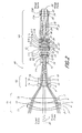
- each lens element is identified by the letter “E” followed by a numeral from 1 through 20 and the general configuration of each lens element is depicted, but the actual radius of each lens surface is set forth below in TABLE 1.
- the lens, object, stop or iris and image surfaces are identified by a numeral from 1 through 36.
- the three lens groups are identified in FIG. 2 by the letter “G” followed by a numeral from 1 through 3 and the liquid lens cell is identified by the letters "LC" and comprises optical surfaces 19 through 23.
- the optical axis is identified in FIG. 2 by a numeral 38.
- Each lens element has its opposite surfaces identified by a separate but consecutive surface number as, for example, lens element E1 has lens surfaces 2 and 3, lens element E9 has lens surfaces 17 and 18 and so forth, as shown in FIG. 2 .
- the location of the object to be imaged, particularly as it relates to focus distance, is identified by a vertical line and the numeral 1 on the optical axis 38 and the real image surface is identified by the numeral 36.
- All of the lens surfaces are spherical or plano except lens surfaces 4 and 8 which are aspheric surfaces that are non-spherical, non-plano but rotationally symmetrical about the optical axis.
- each lens group is defined as the inverse of the focal length.
- the resultant optical power of each group of lenses is as follows: the objective lens group G1 is positive, the zoom lens group G2 is negative and the rear lens group G3 is positive, from a lower positive value to a higher positive value as the shape of the surface in the liquid cell is varied.
- the horizontal arrow with arrowheads on both ends in the upper portion of FIG. 2 indicates that the zoom lens group G2 is movable in both axial directions.
- lens elements While only the lens elements are physically shown in FIG. 2 , it is to be understood that mechanical devices and mechanisms are provided for supporting the lens elements and for causing axial movement of the movable zoom lens group in a lens housing or barrel.
- electronic circuitry changes the profile of the variably shaped optical surface in the liquid lens cell.
- the lens construction and fabrication data for the above described zoom lens system 60 is set forth below in TABLE 1.
- the data in TABLE 1 is given at a temperature of 25° C. (77° F.) and standard atmospheric pressure (760 mm Hg). Throughout this specification measurements are in millimeters (mm) with the exception of wavelengths which are in nanometers (nm).
- the first column "Item” identifies each optical element and each location, i.e. object plane, image plane, etc., with the same numeral or label as used in FIG. 2 .
- the second column identifies the "Group" to which that optical element (lens) belongs with the same numerals used in FIG. 2 .
- the third column “Surface” is a list of the surface numbers of the object (line “1” in FIG. 2 and “Object” in TABLE 1), the Stop (iris) 13 and each of the actual surfaces of the lenses, as identified in FIG. 2 .
- the fourth column “Focus Position” identifies three typical focus positions (F1, F2 and F3) for the zoom lens system 60 wherein there are changes in the distance (separation) between some of the surfaces listed in the third column and there are changes in the radius of curvature of the surface 21 listed in the third column, as described below more thoroughly.
- the fifth column “Separation” is the axial distance between that surface (third column) and the next surface. For example, the distance between surface S2 and surface S3 is 1.725 mm.
- the sixth column is a list of the optical surface radius of curvature for each surface, with a minus sign (-) meaning the center of the radius of curvature is to the left of the surface, as viewed in FIG. 2 and "Infinity” meaning an optically flat surface.
- the asterisk (*) for surfaces 4 and 8 indicate these are aspheric surfaces for which the "radius of curvature” is a base radius. Use of aspherical surfaces provides for the correction of aberrations in the zoom lens while enabling a smaller overall size and a simpler configuration.
- the coefficients for surface 8 are:
- the lens liquid of oil has been selected from a liquid available from Cargille Laboratories, Inc., and water is commonly available from various sources, but it is to be understood that any equivalent, similar or adequate liquid may be used.
- the water liquid at surface 20 has the following refractive indices 1.331152, 1.332987, 1.334468 and 1.337129 at respective wavelengths 656.27, 589.29, 546.07 and 486.13 nanometers.
- the oil liquid at surface 21 has the following refractive indices 1.511501, 1.515000, 1.518002 and 1.523796 at respective wavelengths 656.27, 589.29, 546.07 and 486.13 nanometers.
- the last column of TABLE 1 headed "Aperture Diameter” provides the maximum diameter for each surface through which the light rays pass. All of the maximum aperture diameters, except for the Stop surface 13, are given at a wavelength of 546.1 nanometers for a maximum image diameter of about 6mm and F-numbers of F/2.8 to F/4.0 at the Image Plane, for all Zoom and Focus Positions.
- the maximum aperture diameter of the Stop surface 13 is given in TABLE 1 at a wavelength of 546.1 nanometers and an F-number of F/2.8 at the Image Plane for Zoom Position Z1 and Focus Position F1.
- the Maximum Aperture Diameter is given as an approximate value.
- Zoom lens system 60 is provided with an optical stop at the surface 13 which controls the diameter of the aperture through which light rays may pass at that point.
- the optical stop is the location at which a physical iris (or diaphragm) is located.
- the iris is located before the rear lens group G3 and is axially stationary with that lens group. Note that in FIG. 4A , the rim rays pass through the axis side of the tic marks of the optical stop surface 13 such that the zoom lens system has no vignetting of light beams at any field position, zoom position and focus position. However, note that the F-number varies through zoom and focus positions and the iris opens or closes accordingly.
- the diameter of the iris at zoom positions Z1-Z8 for focus position F1 is 6.71, 6.39, 5.96, 5.53, 5.18, 4.84, 4.63 and 4.61. This shows that the iris located at 13 should close as the focal length increases.
- the diameter of the iris at zoom positions Z1-Z8 for focus positions F2 and F3 changes by a small amount of less than 0.3 mm diameter to maintain the same F-numbers as for focus position F1.
- the focal lengths of zoom lens system 60 for zoom positions Z1-Z8 at focus position F1, at a wavelength of 546.1 nanometers are; 5.89, 7.50, 11.25, 15.00, 18.75, 30.00, 41.25 and 45.00 mm, respectively.
- the corresponding F-numbers for the focal lengths for data positions Z1-Z8, at a wavelength of 546.1 nanometers are; 2.80, 2.90, 3.05, 3.25, 3.45, 3.70, 3.95 and 4.00, respectively.
- Focus Position F1 the Object Plane 1 is assumed to be at infinity, for F2 the Object Plane 1 is at an intermediate distance of about 1016.25 mm, and for F3 the Object Plane 1 is at a close distance of about 378.75 mm (i.e., 378.75 mm away from the image plane).
- the lens groups G1 and G3 remain in the same position throughout the full range of movement of the zoom lens group G2.
- TABLES 2 and 3 provide separation values of surfaces 7 and 12 and TABLE 4 provides the radii of curvature of surface 21 for zoom positions Z1-Z8 and F1-F3.
- the zoom lens system 60 shown in FIG. 2 and prescribed in TABLE 1 has focal lengths for lens groups G1 and G2 of 54.30 and -12.25 mm respectively.
- lens group G3 due to the variable shape of the optical surface 21 between the liquids, has a variable focal length which has a minimum value of +30.18 mm and a maximum value of +38.97 mm at zoom position Z1 and focus position F1, and, zoom position Z8 and focus position F3 respectively.
- the liquid cell LC of zoom lens system 60 is shown in FIGS. 3A and 3B , demonstrating the two extreme radii of curvature from TABLE 1 of the variable shape optical surface 21 between the liquids. In FIGS.
- the two radii of curvature of surface 21 are about -33.99 and +115.80 mm respectively.
- the two extreme focal lengths of the liquid cell LC, in FIGS. 3A and 3B are -185.20 and 630.97 mm respectively. This difference happens at zoom position Z1 and focus position F1, and, zoom position Z8 and focus position F3.
- the volume of the two liquids between surfaces 20, 21 and 21, 22 varies as the shape of the variable surface changes.
- it is also possible to maintain a constant volume for each liquid by applying small, equal but opposite, changes to the axial separation between surfaces 20, 21 and 21,22.
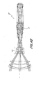
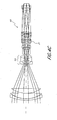
- FIGS. 4A , 4B , and 4C the zoom lens system 60 is shown with the zoom lens group in various positions, the shape of the variable surface in the liquid cell in various positions and with light ray traces for those positions.
- FIG. 4A represents the focus position F1 and zoom position Z1 for which data is set forth above in TABLE 1 with infinity focus and a small focal length of about 5.9 mm.
- FIG. 4B represents the focus position F2 and zoom position Z3 from TABLE 1 with an intermediate focus and a focal length of about 11.3 mm.
- FIG. 4C represents the focus position F3 and zoom position Z8 from TABLE 1 with close focus and a focal length of about 44.8 mm.
- FIGS. 4A , 4B and 4C show three axial locations of the zoom lens group G2 with corresponding three surface shapes for the variable optical surface 21 for the respective zoom and focus positions; Z1, F1 and Z3, F2 and Z8, F3.
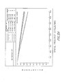
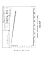
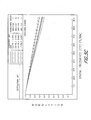
- zoom lens system 60 The optical performance of zoom lens system 60 is given in FIGS. 5A , 5B and 5C wherein the diffraction based polychromatic modulation transfer function ("MTF") data (modulation versus spatial frequency) is shown in percent (%) for five different Field Positions in three different combinations of the zoom and focus positions set forth in TABLE 1, namely (Z1, F1), (Z3, F2) and (Z8, F3) which are representative examples.
- the Field Positions are set forth in two values, both the normalized image height (mm) and the actual object space angle (degree) from the optical axis.
- the MTF percentages are at the wavelengths and weightings set forth in the top right-hand corner of FIGS.
- 5A , 5B and 5C are graphically shown for tangential (T) and radial (R) directions of measurement at the image plane 36. Note that the tangential and radial values are equal at the axial field position (AXIS) and are depicted with only one plot.
- the maximum spatial frequency shown is 90 cycles/mm which given the image diameter of about 6 mm and choice of detector pixel size may provide high quality images at least up to high definition television (HDTV) resolution, namely 1920 pixels horizontally by 1080 pixels vertically.
- HDTV high definition television
- MTF at a spatial frequency is a relatively standard measurement of optical performance, wherein the value "90 cycles/mm" means 90 pairs of black and white lines per millimeter on a chart from which the clarity is determined.
- the highest MTF value is about 89% at the full radial field for zoom position Z1 and focus position F2.
- the lowest MTF value is about 58% at the full tangential field for zoom position Z8 and focus position F3.
- the minimum relative illumination is about 75% at zoom position Z1 and focus position F1.
- higher relative illumination values are better, because a low number means that light is falling off in the corners of the picture.
- High full field relative illumination is preferred for state of the art detectors, which have a constant response to light in all areas and will faithfully reproduce shading in the corners of the image along with changes to the image during zooming. Illumination less than 50% may result in shading in an electronic detector, but will likely be acceptable for film.
- the highest positive distortion is +3.04% at zoom position Z3 and focus position F1 and the lowest negative distortion is -2.98% at zoom position Z1 and focus position F3.
- the so-called "breathing" problem of lenses in general (but which may be more prevalent in zoom lenses) wherein the image changes size from far to close focus is virtually absent in zoom lens system 60 at the short focal length of the zoom range where it is most noticeable due to the large depth of field.
- the lowest breathing is -0.2% at zoom position Z1 and focus position F3 and the highest breathing is -19.5% at zoom position Z8 and focus position F3. Breathing is the percentage change in maximum field angle from infinity focus to a selected focus. Accordingly, at infinity focus (F1), breathing is zero because that is the reference field of view.
- the zoom lens system 60 does provide substantially constant performance, as for example the MTF values, over a temperature range of 0° to 40° C. (32° to 104° F.) and, if a small degradation in performance (MTF) is acceptable, the operable temperature range can be extended to -10° to 50° C. (14° to 122° F.) or more.
- the optimum performance may be achieved by further axial adjustment of the zoom lens group G2 or further change of shape of the contacting optical surface 21 or a combination of both together.
- the liquids may need to be heated or be replaced with doped liquids in a similar way to anti-freeze being added to water in a car radiator for low temperature operation.
- these material temperature changes preferably should not significantly change the optical characteristics of the liquids.
- zoom lens system 60 is of the appropriate dimensions for use with a 6 mm diameter (so called third inch chip sensor), the dimensions of this zoom lens system may be appropriately scaled up or down for use with various film and electronic detector image formats.
- Liquid lens cells may have a limited clear aperture diameter. If a sufficiently small detector is used, the liquid lens cell may be located near the detector. Alternatively, the liquid lens cell may be located near an intermediate image where the light beam "waist" is sufficiently narrow. The liquid lens cell could be placed before the intermediate image, after the intermediate image, or liquid lens cells could be placed both before and after the intermediate image. The waist effect can happen near the stop or the iris. As shown in Table 2, the diameter at the iris is approximately 6.7 mm. Because of the small diameter at the stop or iris, it may be appropriate to place a liquid lens cell in the vicinity of the stop or iris.
- the zoom lens system 60 Among the many advantages of the zoom lens system 60 is that of providing zooming over a wide range of focal lengths utilizing only one axially moving zoom lens group.
- the design of the zoom lens system 60 creates a high performance and mechanically less complex lens system than most conventional high performance zoom lens systems which require at least two axially movable zoom lens groups and corresponding mechanics.
- the unique lens design of the zoom lens system 60 provides focusing over a large region of focus distance without additional movable lens groups and corresponding mechanics.
- the disclosed design of zoom lens system 60 is exemplary, and other designs will fall within the scope of the invention. Other features and advantages of the zoom lens system 60 will appear to those skilled in the art from the foregoing description and the accompanying drawings.
- liquid lens cells to replace one or more moving lens groups results in additional configuration options for the optical path.
- Replacing moving lens groups with liquid lens cells results in a more compact system.
- a linear optical design may result in a lens that is longer than desired.
- the use of liquid lens cells instead of a moving group facilitates the use of optical elements such as folds to redirect of the radiation axis reduce the physical length of a lens.
- the liquid lens cells provide strategic space for folding that reduces the length in one or more directions. This allows longer overall lens lengths to be used in smaller camera packages. For example, many point and shoot cameras and cell phone cameras do not have large amounts of space for a long lens.
- Using liquid cells in combination with folds allows for better lens systems in these small camera packages. Larger cameras can also benefit from reducing the camera package length that would be required for a lens system that did not use folds.
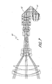
- Fig. 6 shows an optical diagram of a zoom lens system employing liquids and a single fold 41.
- liquids instead of movable lens groups reduces the space requirements and provides additional options for strategic placement of airspaces for fold mirrors or prisms. This figure shows placement of folds where they will not interfere with moving lens groups.
- FIG. 6 shows a single 45 degree fold 41 in the large airspace in the rear lens group G3, to redirect the radiation path by 90 degrees.
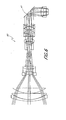
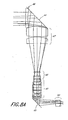
- FIG. 7 is an optical diagram of a zoom lens system employing liquids and a dual fold.
- FIG. 7 shows dual 45 degree folds 42 and 43 in the large airspace in the rear lens group G3, to redirect the radiation path two times by a total of 180 degrees so that the radiation has reversed direction.
- This arrangement may be preferred for packaging of the zoom lens system 60 in a camera box.
- the zoom lens system may have a constant aperture of F/2.8 through all zoom and focus positions but to maintain about the same zoom lens system diameter, some vignetting may occur. In this case, some degradation of image quality may appear but may be partially corrected by re-optimization of the prescription of the zoom lens system.
- the zoom lens system may be arranged so that vignetting does not occur.
- FIGS. 8A and 8B are optical diagrams of a zoom lens system illustrating redirection of the radiation axis with different positions of the zoom lens group and surface shapes between the liquids. This embodiment is illustrative of an alternative lens layout.
- FIG. 8A illustrates a zoom position that enlarges the image to a point that the optic traces exceed parameters of the lens system. This embodiment is illustrative of one design option, and minor changes could be made to the design to correct this effect.
- Folds 44 and 45 are substantially parallel, so that light rays leaving lens elements 50 are substantially parallel to light rays entering the lens system through lens 46.
- Lens group 47 remains fixed, while lens group 48 moves to substantially provide zooming.
- Lens group 49 comprises a liquid lens cell that performs zooming and focusing functions.
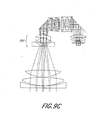
- FIGS. 9A , 9B and 9C are optical diagrams of a zoom lens system where the liquid lens cells and folds have been strategically placed to advantageously shorten the length of the lens system.
- Light enters the lens system through lens group 200.
- Lens group 201 moves to substantially provide zooming.
- the light rays pass through the iris or stop 202 and enter lens group 203 comprising a liquid lens cell.
- Fold 204 directs the light through lens group 205, which comprises a liquid lens cell having a variable surface 206.
- the light rays then pass through lens group 207.
- Fold 208 redirects the light rays through lens group 209 and towards an image plane 210.
- FIG. 9A illustrates a focal length of approximately 6 mm, F/2.8, and infinity focus.
- FIG. 9B illustrates a focal length of approximately 15 mm, F/2.8, and infinity focus.
- FIG. 9C illustrates a focal length of approximately 51 mm, F/2.8 and infinity focus.
- the first liquid lens cell in lens group 203 has a largest clear aperture diameter of approximately 10 mm.
- the second liquid lens cell in lens group 205 has a largest clear aperture diameter of approximately 16 mm.
Claims (6)
- Un système à lentille zoom (60) comprenant :un groupe à lentille d'objectif (G1) qui est stationnaire dans la direction axiale et qui a une puissance optique positive ;un groupe à lentille zoom mobile dans la direction axiale (G2) placé du côté image du groupe à lentille d'objectif (G1) ;un groupe à lentille arrière (G3) stationnaire dans la direction axiale placé du côté image du groupe à lentille zoom mobile dans la direction axiale, le groupe à lentille arrière stationnaire dans la direction axiale comprenant au moins une cellule à lentille liquide, la au moins une cellule à lentille liquide comprenant un premier et un deuxième liquides de contact, une surface optique de contact entre les liquides de contact ayant une forme variable ;un élément d'arrêt optique stationnaire dans la direction axiale placé entre le groupe à lentille zoom mobile dans la direction axiale et le groupe à lentille arrière stationnaire dans la direction axiale ; etun élément optique qui réoriente l'axe de rayonnement, l'élément optique placé à l'intérieur du groupe à lentille arrière stationnaire dans la direction axiale (G3) ;dans lequel le groupe à lentille d'objectif (G1) et le groupe à lentille zoom mobile dans la direction axiale (G2) sont alignés sur un axe optique commun et disposés de manière à collecter le rayonnement émanant d'un espace côté objet du système à lentille zoom et délivrer le rayonnement à un espace côté image.
- Le système à lentille zoom de la revendication 1, dans lequel l'élément optique qui réoriente l'axe du rayonnement comprend un miroir.
- Le système à lentille zoom de la revendication 1, dans lequel l'élément optique qui réoriente l'axe du rayonnement comprend un prisme.
- Le système à lentille zoom de la revendication 1, dans lequel le groupe à lentille zoom mobile (G2), une première partie du groupe à lentille arrière stationnaire dans la direction axiale (G3) et l'élément optique qui réoriente l'axe de rayonnement sont alignés sur un axe optique commun.
- Le système de prise de vues comprenant le système à lentille zoom de la revendication 1, comprenant en outre un élément de capture d'image placé à un point focal du système à lentille zoom, ledit élément de capture d'image étant un CCD.
- Le système de prise de vues comprenant le système à lentille zoom de la revendication 1, comprenant en outre un élément de capture d'image placé à un point focal du système à lentille zoom, ledit élément de capture d'image étant un film.
Applications Claiming Priority (2)
| Application Number | Priority Date | Filing Date | Title |
|---|---|---|---|
| US99224407P | 2007-12-04 | 2007-12-04 | |
| PCT/US2008/084232 WO2009073387A1 (fr) | 2007-12-04 | 2008-11-20 | Objectif de type téléobjectif ayant une lentille liquide dans un groupe fixe |
Publications (2)
| Publication Number | Publication Date |
|---|---|
| EP2217958A1 EP2217958A1 (fr) | 2010-08-18 |
| EP2217958B1 true EP2217958B1 (fr) | 2015-01-07 |
Family
ID=40342169
Family Applications (1)
| Application Number | Title | Priority Date | Filing Date |
|---|---|---|---|
| EP08856236.8A Not-in-force EP2217958B1 (fr) | 2007-12-04 | 2008-11-20 | Objectif de type téléobjectif ayant une lentille liquide dans un groupe fixe |
Country Status (10)
| Country | Link |
|---|---|
| US (2) | US8773766B2 (fr) |
| EP (1) | EP2217958B1 (fr) |
| JP (1) | JP2011509415A (fr) |
| KR (1) | KR101537123B1 (fr) |
| CN (1) | CN101821658B (fr) |
| AU (1) | AU2008331642B2 (fr) |
| CA (1) | CA2703246C (fr) |
| ES (1) | ES2528124T3 (fr) |
| TW (1) | TWI454734B (fr) |
| WO (1) | WO2009073387A1 (fr) |
Families Citing this family (70)
| Publication number | Priority date | Publication date | Assignee | Title |
|---|---|---|---|---|
| JP5635404B2 (ja) | 2007-10-08 | 2014-12-03 | ブラックアイ オプティクス,エルエルシー | 液体光学ズームレンズ及び撮像装置 |
| JP2011509416A (ja) | 2007-12-04 | 2011-03-24 | ブラックアイ オプティクス,エルエルシー | 液体光学による像の安定化 |
| ES2528124T3 (es) | 2007-12-04 | 2015-02-04 | Blackeye Optics, Llc | Lente de zoom de tipo telefoto que tiene una lente líquida en un grupo fijo |
| JP5738841B2 (ja) | 2009-04-10 | 2015-06-24 | ブラックアイ オプティクス,エルエルシー | 可変屈折力光学系 |
| JP5695028B2 (ja) | 2009-04-10 | 2015-04-01 | ブラックアイ オプティクス,エルエルシー | 可変屈折力光学系 |
| US9116295B2 (en) | 2011-06-01 | 2015-08-25 | Hong Kong Applied Science And Technology Research Institute Co. Ltd. | Deformable lens assembly |
| JP6227539B2 (ja) * | 2012-09-20 | 2017-11-08 | 株式会社nittoh | ズームレンズシステムおよび撮像装置 |
| US9715612B2 (en) | 2012-12-26 | 2017-07-25 | Cognex Corporation | Constant magnification lens for vision system camera |
| US10712529B2 (en) | 2013-03-13 | 2020-07-14 | Cognex Corporation | Lens assembly with integrated feedback loop for focus adjustment |
| US11002854B2 (en) | 2013-03-13 | 2021-05-11 | Cognex Corporation | Lens assembly with integrated feedback loop and time-of-flight sensor |
| JP6139713B2 (ja) | 2013-06-13 | 2017-05-31 | コアフォトニクス リミテッド | デュアルアパーチャズームデジタルカメラ |
| CN108549119A (zh) | 2013-07-04 | 2018-09-18 | 核心光电有限公司 | 小型长焦透镜套件 |
| US9857568B2 (en) | 2013-07-04 | 2018-01-02 | Corephotonics Ltd. | Miniature telephoto lens assembly |
| EP3036579A1 (fr) * | 2013-08-20 | 2016-06-29 | Optotune AG | Objectif à focale variable comprenant deux lentilles liquides |
| TWI494599B (zh) | 2014-03-12 | 2015-08-01 | Silicon Touch Tech Inc | 光學變焦結構 |
| CN105025219A (zh) * | 2014-04-30 | 2015-11-04 | 齐发光电股份有限公司 | 图像获取方法 |
| US10830927B2 (en) | 2014-05-06 | 2020-11-10 | Cognex Corporation | System and method for reduction of drift in a vision system variable lens |
| US10795060B2 (en) | 2014-05-06 | 2020-10-06 | Cognex Corporation | System and method for reduction of drift in a vision system variable lens |
| WO2016014655A2 (fr) * | 2014-07-22 | 2016-01-28 | N2 Imaging Systems, LLC | Combinaison de vidéo et de viseur optique |
| US9392188B2 (en) | 2014-08-10 | 2016-07-12 | Corephotonics Ltd. | Zoom dual-aperture camera with folded lens |
| WO2016108093A1 (fr) | 2015-01-03 | 2016-07-07 | Corephotonics Ltd. | Module de lentille de téléobjectif miniature et appareil photographique utilisant un tel module de lentille |
| CN104749755B (zh) * | 2015-03-31 | 2017-07-25 | 中国科学院长春光学精密机械与物理研究所 | 紧凑型三组元大变倍比连续变焦距镜头 |
| JP6618268B2 (ja) * | 2015-04-07 | 2019-12-11 | キヤノン株式会社 | 撮像装置 |
| US10116870B1 (en) * | 2015-06-25 | 2018-10-30 | Cognex Corporation | Single camera vision system for logistics applications |
| CN208060922U (zh) | 2015-09-29 | 2018-11-06 | 富士胶片株式会社 | 投影镜头及投影仪 |
| US10113837B2 (en) | 2015-11-03 | 2018-10-30 | N2 Imaging Systems, LLC | Non-contact optical connections for firearm accessories |
| US10619826B2 (en) * | 2016-08-04 | 2020-04-14 | Abl Ip Holding Llc | Configurable lighting device using a light source, optical modulator, and one or more lenses |
| US10466470B2 (en) | 2016-08-04 | 2019-11-05 | Abl Ip Holding Llc | Configurable optical transducers using an optical modulator and one or more lenses |
| KR101963547B1 (ko) | 2017-02-23 | 2019-03-28 | 코어포토닉스 리미티드 | 폴디드 카메라 렌즈 설계 |
| CN108983403B (zh) * | 2017-06-01 | 2021-02-26 | 诚瑞光学(苏州)有限公司 | 变焦距光学系统 |
| JP2020509420A (ja) | 2017-07-07 | 2020-03-26 | コアフォトニクス リミテッド | 迷光を防止するための屈曲式カメラプリズム設計 |
| IL300459A (en) | 2017-07-23 | 2023-04-01 | Corephotonics Ltd | Compact folded lenses with a large entry key |
| DE102018132699B4 (de) * | 2017-12-19 | 2020-06-18 | Cognex Corporation | Sichtsystem sowie Verstelllinsensystem für ein Sichtsystem |
| KR20220156109A (ko) | 2018-03-02 | 2022-11-24 | 코어포토닉스 리미티드 | 미광을 완화시키기 위한 스페이서 설계 |
| KR20200144552A (ko) * | 2018-04-19 | 2020-12-29 | 옵토튠 컨슈머 아게 | 특히 자동 초점을 위한 얇은 렌즈 광학 모듈 |
| WO2019220255A1 (fr) * | 2018-05-14 | 2019-11-21 | Corephotonics Ltd. | Modèles de lentille de caméra pliée |
| US10753709B2 (en) | 2018-05-17 | 2020-08-25 | Sensors Unlimited, Inc. | Tactical rails, tactical rail systems, and firearm assemblies having tactical rails |
| US10645348B2 (en) | 2018-07-07 | 2020-05-05 | Sensors Unlimited, Inc. | Data communication between image sensors and image displays |
| US11079202B2 (en) | 2018-07-07 | 2021-08-03 | Sensors Unlimited, Inc. | Boresighting peripherals to digital weapon sights |
| US10742913B2 (en) | 2018-08-08 | 2020-08-11 | N2 Imaging Systems, LLC | Shutterless calibration |
| US10921578B2 (en) | 2018-09-07 | 2021-02-16 | Sensors Unlimited, Inc. | Eyecups for optics |
| US11122698B2 (en) | 2018-11-06 | 2021-09-14 | N2 Imaging Systems, LLC | Low stress electronic board retainers and assemblies |
| US10801813B2 (en) | 2018-11-07 | 2020-10-13 | N2 Imaging Systems, LLC | Adjustable-power data rail on a digital weapon sight |
| US10796860B2 (en) | 2018-12-12 | 2020-10-06 | N2 Imaging Systems, LLC | Hermetically sealed over-molded button assembly |
| US11340418B2 (en) * | 2018-12-27 | 2022-05-24 | Tdk Taiwan Corp. | Optical member driving mechanism |
| CN111615822B (zh) | 2019-01-03 | 2022-02-08 | 核心光电有限公司 | 一种双重相机 |
| US11143838B2 (en) | 2019-01-08 | 2021-10-12 | N2 Imaging Systems, LLC | Optical element retainers |
| WO2020172453A1 (fr) * | 2019-02-20 | 2020-08-27 | Mems Optical Zoom Corporation | Ensemble objectif à focale variable |
| CN113167986B (zh) | 2019-02-25 | 2023-09-01 | 核心光电有限公司 | 多光圈相机,具有至少一个两种状态变焦的相机 |
| CN109782380B (zh) * | 2019-03-15 | 2021-05-25 | 苏州思源科安信息技术有限公司 | 一种虹膜成像系统以及虹膜识别模组 |
| CN114578519A (zh) | 2019-08-21 | 2022-06-03 | 核心光电有限公司 | 镜头组件 |
| US11656538B2 (en) | 2019-11-25 | 2023-05-23 | Corephotonics Ltd. | Folded zoom camera module with adaptive aperture |
| CN114667729A (zh) | 2020-01-08 | 2022-06-24 | 核心光电有限公司 | 多孔变焦数码摄像头及其使用方法 |
| US20210263290A1 (en) * | 2020-02-25 | 2021-08-26 | Zebra Technologies Corporation | Optical arrangement for small size wide angle auto focus imaging lens for high resolution sensors |
| KR20210121543A (ko) * | 2020-03-30 | 2021-10-08 | 엘지이노텍 주식회사 | 광학계 및 이를 포함하는 카메라 모듈 |
| KR20210129910A (ko) * | 2020-04-21 | 2021-10-29 | 엘지이노텍 주식회사 | 광학계 및 이를 포함하는 카메라 모듈 |
| KR20210129911A (ko) * | 2020-04-21 | 2021-10-29 | 엘지이노텍 주식회사 | 광학계 및 이를 포함하는 카메라 모듈 |
| US11770609B2 (en) | 2020-05-30 | 2023-09-26 | Corephotonics Ltd. | Systems and methods for obtaining a super macro image |
| CN111854635B (zh) * | 2020-07-06 | 2022-11-11 | 中国科学院光电技术研究所 | 一种基于液体透镜的非球面检测方法 |
| US11914117B2 (en) | 2020-07-31 | 2024-02-27 | Corephotonics Ltd. | Folded macro-tele camera lens designs including six lenses of ++−+−+ or +−++−+, seven lenses of ++−++−+, or eight lenses of ++−++−++ refractive powers |
| TWI767395B (zh) * | 2020-11-04 | 2022-06-11 | 財團法人國家實驗研究院 | 光學取像透鏡組合及包含其之電子取像裝置 |
| KR20220079874A (ko) | 2020-12-01 | 2022-06-14 | 코어포토닉스 리미티드 | 연속적으로 적응하는 줌 팩터를 갖는 폴디드 카메라 |
| CN112649951B (zh) * | 2020-12-23 | 2022-11-01 | 福建福光股份有限公司 | 低畸变广角变焦镜头 |
| KR102474934B1 (ko) | 2021-01-25 | 2022-12-05 | 코어포토닉스 리미티드 | 슬림 팝-아웃 와이드 카메라 렌즈 |
| CN114967079B (zh) * | 2021-02-26 | 2024-02-06 | 北京小米移动软件有限公司 | 微型长焦成像系统、镜头、摄像模组及电子设备 |
| CN113267883B (zh) * | 2021-05-20 | 2022-05-27 | 上海理工大学 | 具有液体透镜的变焦镜头 |
| CN114192972B (zh) * | 2021-12-07 | 2023-09-19 | 潍坊新松机器人自动化有限公司 | 型材表面焊前处理装置 |
| CN114415360B (zh) * | 2021-12-17 | 2024-03-08 | 浙江清华长三角研究院 | 一种新型显微成像系统 |
| US20230273499A1 (en) | 2022-02-28 | 2023-08-31 | Opto Engineering S.P.A. | Zoom lens |
| CN114967086B (zh) * | 2022-07-28 | 2023-01-06 | 歌尔光学科技有限公司 | 投影镜头及投影设备 |
Family Cites Families (88)
| Publication number | Priority date | Publication date | Assignee | Title |
|---|---|---|---|---|
| US3161718A (en) * | 1961-07-12 | 1964-12-15 | William Kurasch | Variable power fluid lens |
| US3366437A (en) * | 1963-03-23 | 1968-01-30 | Sankyo Kigaku Kogyo Kabushiki | Zoom lens having two movable negative lens members disposed between two positive lens members |
| FR2425085A1 (fr) * | 1978-05-05 | 1979-11-30 | Quantel Sa | Objectif a longueur focale variable |
| JPS59116712A (ja) * | 1982-12-24 | 1984-07-05 | Canon Inc | 変倍光学系 |
| US4784479A (en) * | 1984-05-30 | 1988-11-15 | Canon Kabushiki Kaisha | Varifocal optical system |
| JPH0629901B2 (ja) * | 1984-05-30 | 1994-04-20 | キヤノン株式会社 | 変倍光学系 |
| JPS60254014A (ja) | 1984-05-30 | 1985-12-14 | Canon Inc | 変倍光学系 |
| US4871240A (en) * | 1986-12-22 | 1989-10-03 | Canon Kabushiki Kaisha | Zoom lens system having a lens unit with a variable refractive power |
| JPS63208817A (ja) * | 1987-02-25 | 1988-08-30 | Canon Inc | 屈折力可変レンズを有した変倍光学系 |
| JPH01129221A (ja) | 1987-11-13 | 1989-05-22 | Canon Inc | 屈折力可変レンズを有した変倍光学系 |
| JP3109815B2 (ja) * | 1990-05-16 | 2000-11-20 | キヤノン株式会社 | 像安定撮影レンズ系 |
| JPH06160779A (ja) | 1992-11-25 | 1994-06-07 | Canon Inc | 可変頂角プリズム装置を有した防振光学系 |
| JPH09138345A (ja) | 1994-12-28 | 1997-05-27 | Konica Corp | カメラ |
| FR2769375B1 (fr) * | 1997-10-08 | 2001-01-19 | Univ Joseph Fourier | Lentille a focale variable |
| JP3673634B2 (ja) * | 1997-12-22 | 2005-07-20 | キヤノン株式会社 | 撮像装置およびズーム制御方法 |
| US6166864A (en) * | 1998-03-10 | 2000-12-26 | Canon Kabushiki Kaisha | Zoom lens and optical apparatus using the same |
| US6781622B1 (en) * | 1998-06-26 | 2004-08-24 | Ricoh Company, Ltd. | Apparatus for correction based upon detecting a camera shaking |
| DE19942900B4 (de) * | 1998-09-08 | 2004-01-22 | Ricoh Company, Ltd. | Vorrichtung zur Korrektur von Bildfehlern, die durch ein Kameraverwackeln hervorgerufen werden |
| JP2000338533A (ja) * | 1999-05-28 | 2000-12-08 | Olympus Optical Co Ltd | 手ぶれ補正装置 |
| US6449081B1 (en) * | 1999-06-16 | 2002-09-10 | Canon Kabushiki Kaisha | Optical element and optical device having it |
| JP4360504B2 (ja) * | 1999-07-26 | 2009-11-11 | オリンパス株式会社 | ズームレンズ |
| JP4083355B2 (ja) * | 1999-10-08 | 2008-04-30 | オリンパス株式会社 | 撮像装置 |
| US6373640B1 (en) | 2000-01-28 | 2002-04-16 | Concord Camera Corp. | Optical systems for digital cameras |
| US6702483B2 (en) * | 2000-02-17 | 2004-03-09 | Canon Kabushiki Kaisha | Optical element |
| JP4521919B2 (ja) | 2000-03-03 | 2010-08-11 | キヤノン株式会社 | 光学装置 |
| US6806988B2 (en) * | 2000-03-03 | 2004-10-19 | Canon Kabushiki Kaisha | Optical apparatus |
| US7072086B2 (en) * | 2001-10-19 | 2006-07-04 | Batchko Robert G | Digital focus lens system |
| US7672059B2 (en) * | 2000-10-20 | 2010-03-02 | Holochip Corporation | Fluidic lens with electrostatic actuation |
| US6538823B2 (en) * | 2001-06-19 | 2003-03-25 | Lucent Technologies Inc. | Tunable liquid microlens |
| US6965480B2 (en) * | 2001-06-19 | 2005-11-15 | Lucent Technologies Inc. | Method and apparatus for calibrating a tunable microlens |
| JP2003057410A (ja) | 2001-08-21 | 2003-02-26 | Canon Inc | 光学素子および光学機器 |
| JP2003228003A (ja) * | 2002-02-04 | 2003-08-15 | Olympus Optical Co Ltd | 観察光学系 |
| JP4311905B2 (ja) * | 2002-02-05 | 2009-08-12 | オリンパス株式会社 | 光学系 |
| JP2003233007A (ja) * | 2002-02-07 | 2003-08-22 | Olympus Optical Co Ltd | ズーム光学系及びそれを用いた撮像装置 |
| KR101016253B1 (ko) * | 2002-02-14 | 2011-02-25 | 코닌클리케 필립스 일렉트로닉스 엔.브이. | 가변 포커스 렌즈 |
| EP1523691B1 (fr) | 2002-07-22 | 2006-09-06 | Panavision, Inc. | Zoom à très fort rapport de grandissement |
| JP2004064947A (ja) | 2002-07-31 | 2004-02-26 | Meidensha Corp | 電圧形pwmインバータの電圧制御装置 |
| EP1567903B1 (fr) * | 2002-10-25 | 2010-09-01 | Koninklijke Philips Electronics N.V. | Objectif a focale variable |
| WO2004084262A2 (fr) * | 2003-03-17 | 2004-09-30 | Nokia Corporation | Procede et dispositif d'ajustement lateral d'une image |
| ATE499624T1 (de) * | 2003-03-17 | 2011-03-15 | Nokia Corp | Verfahren und einrichtung zum bild-zoomen |
| JP3924546B2 (ja) | 2003-04-04 | 2007-06-06 | 三菱電機株式会社 | 撮像装置 |
| JP2004333640A (ja) * | 2003-05-01 | 2004-11-25 | Olympus Corp | 可変光学素子、光学ユニット及び撮像装置 |
| JP4046163B2 (ja) | 2003-05-27 | 2008-02-13 | 松下電器産業株式会社 | 撮像装置 |
| KR20050033308A (ko) | 2003-10-06 | 2005-04-12 | 삼성전기주식회사 | 액체 렌즈를 이용한 휴대용 단말기의 줌 카메라 및 그제어 시스템과 제어방법 |
| WO2005040866A2 (fr) * | 2003-10-23 | 2005-05-06 | Zeiss Carl Ag | Optique de representation au pouvoir refringent reglable et procede de reglage du pouvoir refringent d'une optique |
| US7141290B2 (en) * | 2003-12-01 | 2006-11-28 | Xymid, Llc | Stitch-bonded fabrics utilizing stretchable substrates |
| GB0406337D0 (en) * | 2004-01-07 | 2004-04-21 | Koninkl Philips Electronics Nv | Zoom optical system |
| EP1709477A1 (fr) | 2004-01-30 | 2006-10-11 | Koninklijke Philips Electronics N.V. | Objectif a focale variable |
| US7535649B2 (en) * | 2004-03-09 | 2009-05-19 | Tang Yin S | Motionless lens systems and methods |
| US7317580B2 (en) * | 2004-03-12 | 2008-01-08 | Konica Minolta Opto, Inc. | Zoom lens |
| GB0408480D0 (en) * | 2004-04-16 | 2004-05-19 | Koninkl Philips Electronics Nv | Variable focus lens having two liquids and electronic device |
| KR20070005689A (ko) * | 2004-04-24 | 2007-01-10 | 코닌클리케 필립스 일렉트로닉스 엔.브이. | 유체 기반 광학 디바이스, 이 디바이스를 제어하는 방법 및전자 디바이스 |
| JP5027661B2 (ja) * | 2004-08-25 | 2012-09-19 | パナビジョン イメージング リミテッド ライアビリティ カンパニー | レンズ制御方法および装置ならびに、これを組み込んだカメラモジュール |
| JP2006064946A (ja) * | 2004-08-26 | 2006-03-09 | Fuji Photo Film Co Ltd | 光学素子、レンズユニット、および撮像装置 |
| JP2006064947A (ja) | 2004-08-26 | 2006-03-09 | Fuji Photo Film Co Ltd | 光学素子、レンズユニット、および撮像装置 |
| KR100616616B1 (ko) * | 2004-09-01 | 2006-08-28 | 삼성전기주식회사 | 카메라 모듈의 자동 초점조절 광학계 |
| US20060072019A1 (en) | 2004-09-29 | 2006-04-06 | Stavely Donald J | System and method for detecting image capture device movement with two dual axis linear accelerometers |
| JP5119567B2 (ja) * | 2004-09-30 | 2013-01-16 | カシオ計算機株式会社 | カメラ |
| US7413306B2 (en) * | 2004-11-18 | 2008-08-19 | Amo Manufacturing Usa, Llc | Sphero cylindrical eye refraction system using fluid focus electrostatically variable lenses |
| FR2878338B1 (fr) * | 2004-11-24 | 2007-03-02 | Varioptic Sa | Monture de lentille a focale variable |
| JP2006178077A (ja) | 2004-12-21 | 2006-07-06 | Sony Corp | ズームレンズ及び撮像装置 |
| US7253966B2 (en) * | 2004-12-24 | 2007-08-07 | Pentax Corporation | Zoom lens system |
| US7403344B2 (en) * | 2005-02-28 | 2008-07-22 | Siimpel Corporation | Lens Assembly |
| JP2006235476A (ja) * | 2005-02-28 | 2006-09-07 | Fuji Photo Film Co Ltd | 光学素子、光学ユニット、および撮像装置 |
| FR2883987B1 (fr) | 2005-03-31 | 2008-02-01 | Varioptic Sa | Systeme optique de formation d'image a reglage de puissance |
| US7227682B2 (en) | 2005-04-08 | 2007-06-05 | Panavision International, L.P. | Wide-range, wide-angle compound zoom with simplified zooming structure |
| US7224535B2 (en) | 2005-07-29 | 2007-05-29 | Panavision International, L.P. | Zoom lens system |
| US7265911B2 (en) * | 2005-08-22 | 2007-09-04 | Eastman Kodak Company | Zoom lens system having variable power element |
| JP2007094170A (ja) | 2005-09-29 | 2007-04-12 | Nikon Corp | 正立変倍アフォーカル光学系 |
| JP2007121821A (ja) * | 2005-10-31 | 2007-05-17 | Sony Corp | 光学素子 |
| KR100711254B1 (ko) * | 2005-11-01 | 2007-04-25 | 삼성전기주식회사 | 액체 줌 렌즈 |
| JP4884783B2 (ja) | 2006-01-19 | 2012-02-29 | 富士フイルム株式会社 | 結像変倍光学系およびこれを用いた撮像装置 |
| EP1993120A1 (fr) * | 2006-03-03 | 2008-11-19 | Nikon Corporation | Appareil et procede d'exposition, et procede de fabrication de l'appareil |
| KR100759510B1 (ko) * | 2006-03-08 | 2007-09-18 | 삼성전기주식회사 | 액체 렌즈 |
| KR100771795B1 (ko) * | 2006-04-20 | 2007-10-30 | 삼성전기주식회사 | 액체렌즈를 구비하는 줌 광학계 |
| EP1870740A1 (fr) * | 2006-06-20 | 2007-12-26 | Varioptic | Commande pour plusieures lentilles liquides |
| US20090185281A1 (en) * | 2006-07-13 | 2009-07-23 | Koninklijke Philips Electronics N.V. | Zoom optical system, and camera and device therewith |
| US7724347B2 (en) | 2006-09-05 | 2010-05-25 | Tunable Optix Corporation | Tunable liquid crystal lens module |
| US7324287B1 (en) | 2006-11-07 | 2008-01-29 | Corning Incorporated | Multi-fluid lenses and optical devices incorporating the same |
| US8027096B2 (en) * | 2006-12-15 | 2011-09-27 | Hand Held Products, Inc. | Focus module and components with actuator polymer control |
| JP2008170874A (ja) | 2007-01-15 | 2008-07-24 | Sony Corp | ズームレンズ及び撮像装置 |
| JP5635404B2 (ja) * | 2007-10-08 | 2014-12-03 | ブラックアイ オプティクス,エルエルシー | 液体光学ズームレンズ及び撮像装置 |
| ES2528124T3 (es) | 2007-12-04 | 2015-02-04 | Blackeye Optics, Llc | Lente de zoom de tipo telefoto que tiene una lente líquida en un grupo fijo |
| JP2011509416A (ja) | 2007-12-04 | 2011-03-24 | ブラックアイ オプティクス,エルエルシー | 液体光学による像の安定化 |
| EP2071367A1 (fr) | 2007-12-13 | 2009-06-17 | Varioptic | Circuit de stabilisation d'image pour lentille liquide |
| JP5738841B2 (ja) * | 2009-04-10 | 2015-06-24 | ブラックアイ オプティクス,エルエルシー | 可変屈折力光学系 |
| JP5695028B2 (ja) | 2009-04-10 | 2015-04-01 | ブラックアイ オプティクス,エルエルシー | 可変屈折力光学系 |
| TWI420140B (zh) * | 2009-09-09 | 2013-12-21 | Ind Tech Res Inst | 變焦鏡頭模組 |
-
2008
- 2008-11-20 ES ES08856236.8T patent/ES2528124T3/es active Active
- 2008-11-20 KR KR1020107009051A patent/KR101537123B1/ko active IP Right Grant
- 2008-11-20 CN CN200880111594.6A patent/CN101821658B/zh not_active Expired - Fee Related
- 2008-11-20 WO PCT/US2008/084232 patent/WO2009073387A1/fr active Application Filing
- 2008-11-20 EP EP08856236.8A patent/EP2217958B1/fr not_active Not-in-force
- 2008-11-20 CA CA2703246A patent/CA2703246C/fr not_active Expired - Fee Related
- 2008-11-20 JP JP2010536971A patent/JP2011509415A/ja active Pending
- 2008-11-20 AU AU2008331642A patent/AU2008331642B2/en not_active Ceased
- 2008-12-02 TW TW097146762A patent/TWI454734B/zh not_active IP Right Cessation
- 2008-12-03 US US12/327,651 patent/US8773766B2/en not_active Expired - Fee Related
-
2014
- 2014-05-23 US US14/286,346 patent/US9658436B2/en not_active Expired - Fee Related
Also Published As
| Publication number | Publication date |
|---|---|
| CN101821658A (zh) | 2010-09-01 |
| AU2008331642A1 (en) | 2009-06-11 |
| JP2011509415A (ja) | 2011-03-24 |
| TWI454734B (zh) | 2014-10-01 |
| AU2008331642B2 (en) | 2014-06-26 |
| CN101821658B (zh) | 2014-02-26 |
| US8773766B2 (en) | 2014-07-08 |
| US20140254025A1 (en) | 2014-09-11 |
| KR101537123B1 (ko) | 2015-07-16 |
| ES2528124T3 (es) | 2015-02-04 |
| EP2217958A1 (fr) | 2010-08-18 |
| US9658436B2 (en) | 2017-05-23 |
| CA2703246C (fr) | 2017-07-11 |
| CA2703246A1 (fr) | 2009-06-11 |
| TW200931059A (en) | 2009-07-16 |
| US20090141365A1 (en) | 2009-06-04 |
| WO2009073387A1 (fr) | 2009-06-11 |
| KR20100082785A (ko) | 2010-07-19 |
| AU2008331642A2 (en) | 2010-05-27 |
Similar Documents
| Publication | Publication Date | Title |
|---|---|---|
| EP2217958B1 (fr) | Objectif de type téléobjectif ayant une lentille liquide dans un groupe fixe | |
| AU2008311114B2 (en) | Liquid optics zoom lens and imaging apparatus | |
| EP2217960B1 (fr) | Système de stabilisation d'image comprenant deux lentilles liquides | |
| US8638496B2 (en) | Variable power optical system |
Legal Events
| Date | Code | Title | Description |
|---|---|---|---|
| PUAI | Public reference made under article 153(3) epc to a published international application that has entered the european phase |
Free format text: ORIGINAL CODE: 0009012 |
|
| 17P | Request for examination filed |
Effective date: 20100616 |
|
| AK | Designated contracting states |
Kind code of ref document: A1 Designated state(s): AT BE BG CH CY CZ DE DK EE ES FI FR GB GR HR HU IE IS IT LI LT LU LV MC MT NL NO PL PT RO SE SI SK TR |
|
| AX | Request for extension of the european patent |
Extension state: AL BA MK RS |
|
| RIN1 | Information on inventor provided before grant (corrected) |
Inventor name: NEIL, IAIN, A. Inventor name: JANNARD, JAMES, H. C/O KNOBBE MARTENS OLSON & BEAR |
|
| DAX | Request for extension of the european patent (deleted) | ||
| 17Q | First examination report despatched |
Effective date: 20140102 |
|
| REG | Reference to a national code |
Ref country code: DE Ref legal event code: R079 Ref document number: 602008036292 Country of ref document: DE Free format text: PREVIOUS MAIN CLASS: G02B0015173000 Ipc: G02B0026000000 |
|
| RIC1 | Information provided on ipc code assigned before grant |
Ipc: G02B 3/14 20060101ALI20140528BHEP Ipc: G02B 7/00 20060101ALI20140528BHEP Ipc: G02B 15/173 20060101ALI20140528BHEP Ipc: G02B 26/00 20060101AFI20140528BHEP |
|
| GRAP | Despatch of communication of intention to grant a patent |
Free format text: ORIGINAL CODE: EPIDOSNIGR1 |
|
| INTG | Intention to grant announced |
Effective date: 20140815 |
|
| RAP1 | Party data changed (applicant data changed or rights of an application transferred) |
Owner name: BLACKEYE OPTICS, LLC |
|
| GRAS | Grant fee paid |
Free format text: ORIGINAL CODE: EPIDOSNIGR3 |
|
| GRAA | (expected) grant |
Free format text: ORIGINAL CODE: 0009210 |
|
| AK | Designated contracting states |
Kind code of ref document: B1 Designated state(s): AT BE BG CH CY CZ DE DK EE ES FI FR GB GR HR HU IE IS IT LI LT LU LV MC MT NL NO PL PT RO SE SI SK TR |
|
| REG | Reference to a national code |
Ref country code: GB Ref legal event code: FG4D |
|
| REG | Reference to a national code |
Ref country code: CH Ref legal event code: EP |
|
| REG | Reference to a national code |
Ref country code: IE Ref legal event code: FG4D |
|
| REG | Reference to a national code |
Ref country code: ES Ref legal event code: FG2A Ref document number: 2528124 Country of ref document: ES Kind code of ref document: T3 Effective date: 20150204 |
|
| REG | Reference to a national code |
Ref country code: NL Ref legal event code: T3 |
|
| REG | Reference to a national code |
Ref country code: AT Ref legal event code: REF Ref document number: 706111 Country of ref document: AT Kind code of ref document: T Effective date: 20150215 |
|
| REG | Reference to a national code |
Ref country code: SE Ref legal event code: TRGR |
|
| REG | Reference to a national code |
Ref country code: DE Ref legal event code: R096 Ref document number: 602008036292 Country of ref document: DE Effective date: 20150226 |
|
| REG | Reference to a national code |
Ref country code: AT Ref legal event code: MK05 Ref document number: 706111 Country of ref document: AT Kind code of ref document: T Effective date: 20150107 |
|
| REG | Reference to a national code |
Ref country code: LT Ref legal event code: MG4D |
|
| PG25 | Lapsed in a contracting state [announced via postgrant information from national office to epo] |
Ref country code: NO Free format text: LAPSE BECAUSE OF FAILURE TO SUBMIT A TRANSLATION OF THE DESCRIPTION OR TO PAY THE FEE WITHIN THE PRESCRIBED TIME-LIMIT Effective date: 20150407 Ref country code: BG Free format text: LAPSE BECAUSE OF FAILURE TO SUBMIT A TRANSLATION OF THE DESCRIPTION OR TO PAY THE FEE WITHIN THE PRESCRIBED TIME-LIMIT Effective date: 20150407 Ref country code: HR Free format text: LAPSE BECAUSE OF FAILURE TO SUBMIT A TRANSLATION OF THE DESCRIPTION OR TO PAY THE FEE WITHIN THE PRESCRIBED TIME-LIMIT Effective date: 20150107 Ref country code: LT Free format text: LAPSE BECAUSE OF FAILURE TO SUBMIT A TRANSLATION OF THE DESCRIPTION OR TO PAY THE FEE WITHIN THE PRESCRIBED TIME-LIMIT Effective date: 20150107 |
|
| PG25 | Lapsed in a contracting state [announced via postgrant information from national office to epo] |
Ref country code: PL Free format text: LAPSE BECAUSE OF FAILURE TO SUBMIT A TRANSLATION OF THE DESCRIPTION OR TO PAY THE FEE WITHIN THE PRESCRIBED TIME-LIMIT Effective date: 20150107 Ref country code: LV Free format text: LAPSE BECAUSE OF FAILURE TO SUBMIT A TRANSLATION OF THE DESCRIPTION OR TO PAY THE FEE WITHIN THE PRESCRIBED TIME-LIMIT Effective date: 20150107 Ref country code: GR Free format text: LAPSE BECAUSE OF FAILURE TO SUBMIT A TRANSLATION OF THE DESCRIPTION OR TO PAY THE FEE WITHIN THE PRESCRIBED TIME-LIMIT Effective date: 20150408 Ref country code: IS Free format text: LAPSE BECAUSE OF FAILURE TO SUBMIT A TRANSLATION OF THE DESCRIPTION OR TO PAY THE FEE WITHIN THE PRESCRIBED TIME-LIMIT Effective date: 20150507 Ref country code: AT Free format text: LAPSE BECAUSE OF FAILURE TO SUBMIT A TRANSLATION OF THE DESCRIPTION OR TO PAY THE FEE WITHIN THE PRESCRIBED TIME-LIMIT Effective date: 20150107 |
|
| REG | Reference to a national code |
Ref country code: FR Ref legal event code: PLFP Year of fee payment: 8 Ref country code: DE Ref legal event code: R097 Ref document number: 602008036292 Country of ref document: DE |
|
| PG25 | Lapsed in a contracting state [announced via postgrant information from national office to epo] |
Ref country code: CZ Free format text: LAPSE BECAUSE OF FAILURE TO SUBMIT A TRANSLATION OF THE DESCRIPTION OR TO PAY THE FEE WITHIN THE PRESCRIBED TIME-LIMIT Effective date: 20150107 Ref country code: RO Free format text: LAPSE BECAUSE OF FAILURE TO SUBMIT A TRANSLATION OF THE DESCRIPTION OR TO PAY THE FEE WITHIN THE PRESCRIBED TIME-LIMIT Effective date: 20150107 Ref country code: EE Free format text: LAPSE BECAUSE OF FAILURE TO SUBMIT A TRANSLATION OF THE DESCRIPTION OR TO PAY THE FEE WITHIN THE PRESCRIBED TIME-LIMIT Effective date: 20150107 Ref country code: SK Free format text: LAPSE BECAUSE OF FAILURE TO SUBMIT A TRANSLATION OF THE DESCRIPTION OR TO PAY THE FEE WITHIN THE PRESCRIBED TIME-LIMIT Effective date: 20150107 Ref country code: DK Free format text: LAPSE BECAUSE OF FAILURE TO SUBMIT A TRANSLATION OF THE DESCRIPTION OR TO PAY THE FEE WITHIN THE PRESCRIBED TIME-LIMIT Effective date: 20150107 |
|
| PLBE | No opposition filed within time limit |
Free format text: ORIGINAL CODE: 0009261 |
|
| STAA | Information on the status of an ep patent application or granted ep patent |
Free format text: STATUS: NO OPPOSITION FILED WITHIN TIME LIMIT |
|
| 26N | No opposition filed |
Effective date: 20151008 |
|
| PG25 | Lapsed in a contracting state [announced via postgrant information from national office to epo] |
Ref country code: SI Free format text: LAPSE BECAUSE OF FAILURE TO SUBMIT A TRANSLATION OF THE DESCRIPTION OR TO PAY THE FEE WITHIN THE PRESCRIBED TIME-LIMIT Effective date: 20150107 |
|
| PG25 | Lapsed in a contracting state [announced via postgrant information from national office to epo] |
Ref country code: BE Free format text: LAPSE BECAUSE OF FAILURE TO SUBMIT A TRANSLATION OF THE DESCRIPTION OR TO PAY THE FEE WITHIN THE PRESCRIBED TIME-LIMIT Effective date: 20150107 |
|
| PG25 | Lapsed in a contracting state [announced via postgrant information from national office to epo] |
Ref country code: MC Free format text: LAPSE BECAUSE OF FAILURE TO SUBMIT A TRANSLATION OF THE DESCRIPTION OR TO PAY THE FEE WITHIN THE PRESCRIBED TIME-LIMIT Effective date: 20150107 Ref country code: LU Free format text: LAPSE BECAUSE OF FAILURE TO SUBMIT A TRANSLATION OF THE DESCRIPTION OR TO PAY THE FEE WITHIN THE PRESCRIBED TIME-LIMIT Effective date: 20151120 |
|
| REG | Reference to a national code |
Ref country code: CH Ref legal event code: PL |
|
| PG25 | Lapsed in a contracting state [announced via postgrant information from national office to epo] |
Ref country code: LI Free format text: LAPSE BECAUSE OF NON-PAYMENT OF DUE FEES Effective date: 20151130 Ref country code: CH Free format text: LAPSE BECAUSE OF NON-PAYMENT OF DUE FEES Effective date: 20151130 |
|
| REG | Reference to a national code |
Ref country code: IE Ref legal event code: MM4A |
|
| REG | Reference to a national code |
Ref country code: FR Ref legal event code: PLFP Year of fee payment: 9 |
|
| PG25 | Lapsed in a contracting state [announced via postgrant information from national office to epo] |
Ref country code: IE Free format text: LAPSE BECAUSE OF NON-PAYMENT OF DUE FEES Effective date: 20151120 |
|
| PG25 | Lapsed in a contracting state [announced via postgrant information from national office to epo] |
Ref country code: HU Free format text: LAPSE BECAUSE OF FAILURE TO SUBMIT A TRANSLATION OF THE DESCRIPTION OR TO PAY THE FEE WITHIN THE PRESCRIBED TIME-LIMIT; INVALID AB INITIO Effective date: 20081120 |
|
| PG25 | Lapsed in a contracting state [announced via postgrant information from national office to epo] |
Ref country code: CY Free format text: LAPSE BECAUSE OF FAILURE TO SUBMIT A TRANSLATION OF THE DESCRIPTION OR TO PAY THE FEE WITHIN THE PRESCRIBED TIME-LIMIT Effective date: 20150107 |
|
| PG25 | Lapsed in a contracting state [announced via postgrant information from national office to epo] |
Ref country code: MT Free format text: LAPSE BECAUSE OF FAILURE TO SUBMIT A TRANSLATION OF THE DESCRIPTION OR TO PAY THE FEE WITHIN THE PRESCRIBED TIME-LIMIT Effective date: 20150107 Ref country code: TR Free format text: LAPSE BECAUSE OF FAILURE TO SUBMIT A TRANSLATION OF THE DESCRIPTION OR TO PAY THE FEE WITHIN THE PRESCRIBED TIME-LIMIT Effective date: 20150107 |
|
| REG | Reference to a national code |
Ref country code: FR Ref legal event code: PLFP Year of fee payment: 10 |
|
| PG25 | Lapsed in a contracting state [announced via postgrant information from national office to epo] |
Ref country code: PT Free format text: LAPSE BECAUSE OF FAILURE TO SUBMIT A TRANSLATION OF THE DESCRIPTION OR TO PAY THE FEE WITHIN THE PRESCRIBED TIME-LIMIT Effective date: 20150107 |
|
| REG | Reference to a national code |
Ref country code: FR Ref legal event code: PLFP Year of fee payment: 11 |
|
| PGFP | Annual fee paid to national office [announced via postgrant information from national office to epo] |
Ref country code: ES Payment date: 20181203 Year of fee payment: 11 |
|
| PGFP | Annual fee paid to national office [announced via postgrant information from national office to epo] |
Ref country code: SE Payment date: 20191111 Year of fee payment: 12 Ref country code: FI Payment date: 20191111 Year of fee payment: 12 Ref country code: DE Payment date: 20191105 Year of fee payment: 12 Ref country code: NL Payment date: 20191114 Year of fee payment: 12 |
|
| PGFP | Annual fee paid to national office [announced via postgrant information from national office to epo] |
Ref country code: FR Payment date: 20191014 Year of fee payment: 12 Ref country code: IT Payment date: 20191108 Year of fee payment: 12 |
|
| PGFP | Annual fee paid to national office [announced via postgrant information from national office to epo] |
Ref country code: GB Payment date: 20191122 Year of fee payment: 12 |
|
| REG | Reference to a national code |
Ref country code: DE Ref legal event code: R082 Ref document number: 602008036292 Country of ref document: DE |
|
| REG | Reference to a national code |
Ref country code: ES Ref legal event code: FD2A Effective date: 20210601 Ref country code: DE Ref legal event code: R119 Ref document number: 602008036292 Country of ref document: DE |
|
| REG | Reference to a national code |
Ref country code: FI Ref legal event code: MAE |
|
| REG | Reference to a national code |
Ref country code: SE Ref legal event code: EUG |
|
| REG | Reference to a national code |
Ref country code: NL Ref legal event code: MM Effective date: 20201201 |
|
| GBPC | Gb: european patent ceased through non-payment of renewal fee |
Effective date: 20201120 |
|
| PG25 | Lapsed in a contracting state [announced via postgrant information from national office to epo] |
Ref country code: FI Free format text: LAPSE BECAUSE OF NON-PAYMENT OF DUE FEES Effective date: 20201120 |
|
| PG25 | Lapsed in a contracting state [announced via postgrant information from national office to epo] |
Ref country code: NL Free format text: LAPSE BECAUSE OF NON-PAYMENT OF DUE FEES Effective date: 20201201 Ref country code: SE Free format text: LAPSE BECAUSE OF NON-PAYMENT OF DUE FEES Effective date: 20201121 Ref country code: ES Free format text: LAPSE BECAUSE OF NON-PAYMENT OF DUE FEES Effective date: 20191121 |
|
| PG25 | Lapsed in a contracting state [announced via postgrant information from national office to epo] |
Ref country code: FR Free format text: LAPSE BECAUSE OF NON-PAYMENT OF DUE FEES Effective date: 20201130 Ref country code: IT Free format text: LAPSE BECAUSE OF NON-PAYMENT OF DUE FEES Effective date: 20201120 |
|
| PG25 | Lapsed in a contracting state [announced via postgrant information from national office to epo] |
Ref country code: GB Free format text: LAPSE BECAUSE OF NON-PAYMENT OF DUE FEES Effective date: 20201120 Ref country code: DE Free format text: LAPSE BECAUSE OF NON-PAYMENT OF DUE FEES Effective date: 20210601 |