EP2135667A1 - Cavitator - Google Patents
Cavitator Download PDFInfo
- Publication number
- EP2135667A1 EP2135667A1 EP09163116A EP09163116A EP2135667A1 EP 2135667 A1 EP2135667 A1 EP 2135667A1 EP 09163116 A EP09163116 A EP 09163116A EP 09163116 A EP09163116 A EP 09163116A EP 2135667 A1 EP2135667 A1 EP 2135667A1
- Authority
- EP
- European Patent Office
- Prior art keywords
- cavitator
- obstacle
- axial
- cross
- bodies
- Prior art date
- Legal status (The legal status is an assumption and is not a legal conclusion. Google has not performed a legal analysis and makes no representation as to the accuracy of the status listed.)
- Granted
Links
- 239000000203 mixture Substances 0.000 claims abstract description 16
- 238000004140 cleaning Methods 0.000 claims description 9
- 230000003247 decreasing effect Effects 0.000 claims description 4
- 239000007788 liquid Substances 0.000 claims description 4
- 239000011148 porous material Substances 0.000 claims description 4
- 238000007373 indentation Methods 0.000 claims description 3
- 239000007787 solid Substances 0.000 claims description 3
- 230000007704 transition Effects 0.000 claims description 3
- 230000004323 axial length Effects 0.000 claims description 2
- 238000006073 displacement reaction Methods 0.000 claims description 2
- 238000011144 upstream manufacturing Methods 0.000 claims description 2
- 230000000087 stabilizing effect Effects 0.000 claims 1
- 230000004888 barrier function Effects 0.000 abstract 3
- 238000007599 discharging Methods 0.000 abstract 1
- 230000000694 effects Effects 0.000 description 9
- 244000052616 bacterial pathogen Species 0.000 description 6
- 238000004519 manufacturing process Methods 0.000 description 5
- 230000015572 biosynthetic process Effects 0.000 description 4
- 230000003068 static effect Effects 0.000 description 4
- 239000000839 emulsion Substances 0.000 description 3
- 239000000725 suspension Substances 0.000 description 3
- 230000001154 acute effect Effects 0.000 description 2
- 238000013459 approach Methods 0.000 description 2
- 230000001419 dependent effect Effects 0.000 description 2
- 230000008021 deposition Effects 0.000 description 2
- 239000000463 material Substances 0.000 description 2
- XLYOFNOQVPJJNP-UHFFFAOYSA-N water Substances O XLYOFNOQVPJJNP-UHFFFAOYSA-N 0.000 description 2
- 238000003466 welding Methods 0.000 description 2
- 241000792859 Enema Species 0.000 description 1
- 238000009825 accumulation Methods 0.000 description 1
- 230000001914 calming effect Effects 0.000 description 1
- 239000012459 cleaning agent Substances 0.000 description 1
- 238000011109 contamination Methods 0.000 description 1
- 238000005520 cutting process Methods 0.000 description 1
- 230000007423 decrease Effects 0.000 description 1
- 230000018109 developmental process Effects 0.000 description 1
- 239000007920 enema Substances 0.000 description 1
- 229940095399 enema Drugs 0.000 description 1
- 230000007613 environmental effect Effects 0.000 description 1
- 239000012530 fluid Substances 0.000 description 1
- 238000011031 large-scale manufacturing process Methods 0.000 description 1
- 239000002184 metal Substances 0.000 description 1
- 230000006911 nucleation Effects 0.000 description 1
- 238000010899 nucleation Methods 0.000 description 1
- 230000002093 peripheral effect Effects 0.000 description 1
- 230000006641 stabilisation Effects 0.000 description 1
- 238000011105 stabilization Methods 0.000 description 1
- 229910001220 stainless steel Inorganic materials 0.000 description 1
- 239000010935 stainless steel Substances 0.000 description 1
Images
Classifications
-
- B—PERFORMING OPERATIONS; TRANSPORTING
- B01—PHYSICAL OR CHEMICAL PROCESSES OR APPARATUS IN GENERAL
- B01F—MIXING, e.g. DISSOLVING, EMULSIFYING OR DISPERSING
- B01F25/00—Flow mixers; Mixers for falling materials, e.g. solid particles
- B01F25/40—Static mixers
- B01F25/42—Static mixers in which the mixing is affected by moving the components jointly in changing directions, e.g. in tubes provided with baffles or obstructions
- B01F25/43—Mixing tubes, e.g. wherein the material is moved in a radial or partly reversed direction
- B01F25/433—Mixing tubes wherein the shape of the tube influences the mixing, e.g. mixing tubes with varying cross-section or provided with inwardly extending profiles
- B01F25/4335—Mixers with a converging-diverging cross-section
-
- B—PERFORMING OPERATIONS; TRANSPORTING
- B01—PHYSICAL OR CHEMICAL PROCESSES OR APPARATUS IN GENERAL
- B01F—MIXING, e.g. DISSOLVING, EMULSIFYING OR DISPERSING
- B01F25/00—Flow mixers; Mixers for falling materials, e.g. solid particles
- B01F25/40—Static mixers
- B01F25/42—Static mixers in which the mixing is affected by moving the components jointly in changing directions, e.g. in tubes provided with baffles or obstructions
- B01F25/43—Mixing tubes, e.g. wherein the material is moved in a radial or partly reversed direction
- B01F25/431—Straight mixing tubes with baffles or obstructions that do not cause substantial pressure drop; Baffles therefor
- B01F25/4316—Straight mixing tubes with baffles or obstructions that do not cause substantial pressure drop; Baffles therefor the baffles being flat pieces of material, e.g. intermeshing, fixed to the wall or fixed on a central rod
- B01F25/43163—Straight mixing tubes with baffles or obstructions that do not cause substantial pressure drop; Baffles therefor the baffles being flat pieces of material, e.g. intermeshing, fixed to the wall or fixed on a central rod in the form of small flat plate-like elements
-
- B—PERFORMING OPERATIONS; TRANSPORTING
- B01—PHYSICAL OR CHEMICAL PROCESSES OR APPARATUS IN GENERAL
- B01F—MIXING, e.g. DISSOLVING, EMULSIFYING OR DISPERSING
- B01F25/00—Flow mixers; Mixers for falling materials, e.g. solid particles
- B01F25/40—Static mixers
- B01F25/42—Static mixers in which the mixing is affected by moving the components jointly in changing directions, e.g. in tubes provided with baffles or obstructions
- B01F25/43—Mixing tubes, e.g. wherein the material is moved in a radial or partly reversed direction
- B01F25/431—Straight mixing tubes with baffles or obstructions that do not cause substantial pressure drop; Baffles therefor
- B01F25/43197—Straight mixing tubes with baffles or obstructions that do not cause substantial pressure drop; Baffles therefor characterised by the mounting of the baffles or obstructions
- B01F25/431972—Mounted on an axial support member, e.g. a rod or bar
-
- B—PERFORMING OPERATIONS; TRANSPORTING
- B01—PHYSICAL OR CHEMICAL PROCESSES OR APPARATUS IN GENERAL
- B01F—MIXING, e.g. DISSOLVING, EMULSIFYING OR DISPERSING
- B01F25/00—Flow mixers; Mixers for falling materials, e.g. solid particles
- B01F25/40—Static mixers
- B01F25/42—Static mixers in which the mixing is affected by moving the components jointly in changing directions, e.g. in tubes provided with baffles or obstructions
- B01F25/43—Mixing tubes, e.g. wherein the material is moved in a radial or partly reversed direction
- B01F25/433—Mixing tubes wherein the shape of the tube influences the mixing, e.g. mixing tubes with varying cross-section or provided with inwardly extending profiles
- B01F25/4338—Mixers with a succession of converging-diverging cross-sections, i.e. undulating cross-section
Definitions
- the invention relates to a hydrodynamic cavitation mixer.
- the so-called cavitation bubbles occurs near the interface between two phase regions, say large oil droplets in water, the second component, in this case the oil droplets, is torn into smaller units and thereby a very fine mixing of the two components and thus produces a very stable suspension or emulsion.
- cavitation bubbles is done in a flowing liquid by a drop in the static pressure below the vapor pressure of the liquid, thereby forming vapor-filled gas bubbles, eg. B. due to a current narrowing.
- the static pressure becomes zero or negative in the case of water when the flow velocity reaches a certain value dependent on environmental conditions, e.g. B. at the trailing edges about 14 m / sec., Exceeds.
- the constriction and subsequent expansion of the flow cross section can be achieved by an obstacle body is arranged in a flow chamber, wherein the remaining gap z. B. between obstacle body and surrounding housing of the flow chamber forms the bottleneck.
- cavitation fields forming in the cavities field form in the cavities between the obstacle bodies, and the spatial superposition of the individual cavitation fields creates a so-called super-cavitation field, which causes a multiplication of the cavitation effect of each individual cavitation field.
- the reduction of the annular gap area in the direction of flow is z. B. caused by a decreasing in the pressure flow direction cross section of the Kavitatorrohres and a particular smaller analog diameter obstacle, so the obstacle body on the axial rod, and the axial displacement of the entire Obstisbäumchens relative to Kavitatorrohr by the Axialstange of Obstacle tree axially from a closed end the Cavitatorrohres is led out and can be adjusted axially there.
- Kavitatorrohr composed of several individual parts, especially in the axial direction adjoining individual parts, but also from two split in the longitudinal half shells, so must be arranged between gaskets that leave between seal and surrounding material smallest cavities in which collect and multiply germs can.
- the individual parts which are to be joined together usually to be screwed, must fit tightly against one another and as cavity-free as possible in order to reduce these possibilities of contamination as far as possible.
- the cavitator tube is made from as few as possible, in particular a single piece, then either the production effort is very high or the assembly of the obstacle tree to be arranged therein is not possible or very expensive.
- welds are in areas in which only laminar flows prevail during operation of the cavitator, these areas are not optimally self-cleaned by the flow of the medium.
- Kavitatorrohr consists of individual sections, in particular separate sections for product inlet, Kavitationskonus and AxialstangenDurch Insert in the flow direction one behind the other, arranged on these individual pipe sections welds can be achieved before Georgiaflanschen well and the welds are reworked, in particular sanded or otherwise and manner of the surface of the weld to be eliminated to the interior of the cavitator out.
- the Befest onlysfla n cal are not welded to these individual pipe sections but made in one piece with these pipe sections from the solid, in particular turned from solid, so that no welds arise that can raise the problems described.
- the discharge chamber which contains the radially outflowing product outlet, is a purchased as a purchased part tee, which thus may indeed have a weld between the radial pipe section and extending in the longitudinal direction pipe section, but this weld was pore-free treated by the manufacturer, which is possible in mass production and specialized devices.
- the required flanges are welded and the welds aftertreated to close pores.
- gap-free seals in particular so-called germ-free seals, are used, which prevent the deposition of germs for lack of residual space between seal and surrounding material and in the seal.
- the arrangement of seals is recommended in such a manner that the main flow direction does not coincide with the direction of the seals, so the seals are preferably arranged in the circumferential direction or radial transverse direction of the main flow direction, and thus the individual sections of which the Kavitatorrohr consists , connect to each other in the axial direction.
- the transitions between the obstacle bodies and the axial bar carrying them executed rounded, in particular with a radius of curvature of at least 1 mm, better at least 10 mm, and also all inner edges , In particular annular inner edges, on the inner surfaces of the cavitator, in particular the inner edges between cylindrical and conical sections of the cavitator.
- a very critical area from a hygienic point of view is still the passage of the axial rod through the front end of the closed Kavitatorrohres, namely the portion of the Axialstangen take arrangement.
- the annular gap between the axial rod and the receiving, surrounding component is preferably sealed with a gap-free, in particular germ-free, seal such as a lip seal and only in the simple case of an O-ring seal.
- the product inlet preferably takes place for the main component in the axial direction through a corresponding opening in the product inlet, wherein the components to be added are supplied at a lower proportion than the main component preferably via corresponding radially outflowing supply lines in the product inlet, and preferably in or before the first cross-sectional constriction in the section of product enema.
- baffle By forming the first obstacle body as a baffle plate, so with one of the flow direction of the first component as strong a obstacle bidding, baffle, which is even or concave against the onflowing first component, alternatively by this first obstacle body through countercurrent second Component be supplied so that the two components in the area at or immediately before the Already by the impact of the first component, the impact surface should be strongly mixed with the baffle plate.
- an already existing mixture may be processed with an analogous device for the purpose of stabilization, by then supplying the mixture to be stabilized instead of the first component, and no further component being supplied beyond, thus also no inlet opening for the second Component as well as a supply piping is needed.
- the impact and the mixing is therefore particularly strong mixing, because beyond the first obstacle body, the flow direction of the first component counteracting, no support the flow is opposed, because this first as well as the following obstacle bodies can be formed on a particular in the form of a central axis Holder, which approaches from the opposite direction, ie opposite to the flow direction of the first component, are held in the center of the flow chamber.
- a cross-sectional constriction and then a cross-sectional expansion both preferably in a cone shape, passes through the cross-sectional expansion, a negative pressure generated by the first component in the flow chamber in front of the baffle plate, which supplies the second component into the flow chamber sucked in and also improves the mixing.
- a smaller in terms of its area flow gap measured in the main flow direction ie the flow direction of both the first component alone and the mixture from the supply of the second component, can be achieved in particular in combination with the impact of the first component on the first obstacle body that the Remove obstacle body in its cross section in the main flow direction and so that the length of the annular gap around the obstacle body around, and thus form a narrowing in the flow direction cone.
- the wall of the surrounding housing can run parallel to the cone of the obstacle body or even be formed more conical (larger angle at the apex of the cone), which further increases the effect of the decreasing annular surface.
- a weaker cone shape (lesser angle) at the top of the cone of the housing is possible, which weakens the effect caused by the conical shape of the obstacle body somewhat.
- the concavely formed impact surface causes - above all with more or less centric impingement of the first component on the baffle plate and centric feeding of the second component - an approximately toroidal turbulence of the mixture and thereby a new approach of the rebounded from the baffle mixture to the baffle, where the mixture is additionally mixed again by the again impinging first component.
- the effect can be further improved by the supply of the second component on the baffle of the first obstacle body is not distributed centrally, but decentralized distributed at several input openings annularly around the center of the baffle, and the impact of the first component remains central.
- the central axis for fixing the obstacle body can be used at the same time hollow as a pipe for feeding the second component to the baffle.
- the mixture produced is discharged via an outlet opening, which flows out of the housing preferably radially, in particular in the form of a radial annular gap.
- the efficiency of the device which is usually used in an existing pipeline, can be increased by - for example, depending on the flow rate in the feeding tube, the viscosity of the individual components and their miscibility - the obstacle bodies are axially adjusted, in their Distance to each other and / or in groups or even total relative to the surrounding housing, whereby in a conical housing and the absolute size of the annular gap surfaces is changed.
- the obstacle bodies are on the one hand plate-shaped in order to simplify and reduce production, and in particular are made so thin that they can oscillate at their free edges in the direction of flow, which facilitates the generation and tearing off of vapor bubbles.
- the flow gap between obstacle bodies and housing can at z.
- the plate-shaped obstacle body at its radially outermost point quite reach the housing and are connected to this, but not for example over the entire circumference, but only in segments, and in the segments between radially extending slots or gaps are present, which can be offset from each other in the axial direction from one obstacle body to the next and serve as flow-through gaps.
- the surrounding housing - viewed in the axial direction - may be formed analogously, so that over the entire circumference a respective constant cross section between the housing and spoiler edge is met or the housing is formed inside continuously round, so that change in the circumferential direction, the distances to the trailing edge.
- the cross-sectional constriction should be dimensioned after the inlet opening so that the flow velocity at the narrowest point of the cross-sectional constriction corresponds to the flow velocity in the flow gap of the last obstacle body.
- the flow rate behind it, at the outlet after the last obstacle body should be slightly higher than in the flow gap at the last obstacle body.
- a particularly simple embodiment is provided when round disks with a diameter that remains the same in the flow direction are used as obstacle bodies, and the decreasing annular gap is achieved by the housing tapering in the main flow direction.
- this effect is less pronounced than with conically smaller obstacle bodies, in particular slices.
- a strong cross-sectional constriction downstream of the inlet opening is particularly advantageous, so that the flow velocity increases by a factor of 9-13, in particular by a factor of 10.sup.-12, in particular by a factor of 10.5-11, from the inlet opening to the narrowest point of the cross-sectional constriction. 5, increased.
- the obstacle bodies are positioned and dimensioned relative to one another and / or to the surrounding housing in such a way that the flow velocity in the flow gap at the last obstacle body in the flow direction is 1.8 to 2.5 compared to the passage gap for the first obstacle body. in particular increased by 2.0 - 2.3.
- the thickness is between 1 and 4 mm, in particular between 2 and 3 mm, in the case of metal disks, in particular made of stainless steel, the production is very simple, in particular a cutting edge standing at right angles to the main plane of the plates can be used. and the plates are still sufficiently elastic.
- the axial distance from center to center of two adjacent obstacle body should be between two and seven times the thickness of the plates, in particular three times to five times.
- the radial width of the annular gap between the outer circumference of the plate-shaped obstacle body and the housing should be between 1 and 5 mm, in particular between 1.5 and 3.8 mm.
- an axial length of the constant cross-section of the housing between the cross-sectional expansion and the baffle plate of 0.7 to 1.4 times the diameter after cross-sectional expansion, that is, the constant cross-section, has been found to be advantageous.
- the inner free diameter after the cross-sectional expansion so on the route with a constant cross section between 0.9 and 2.0 times, in particular between 0.9 and 1.1 times, the free cross section of supply and / or discharge piping amount.
- the first obstacle body formed as a baffle plate will have a substantially greater extent in the axial direction than the remaining, rather plate-shaped obstacle bodies.
- These thicker in the axial direction first obstacle body preferably have on its outer circumference on an annular circumferential concave indentation, so that they each have two annular circumferential, axially spaced Abrisskanten, the indentation should correspond to at least the size of the radial width of the annular gap, preferably a multiple of this gap.
- the demolition edges are particularly effective when viewed in cross-section have an acute angle of less than 60 °, in particular less than 50 ° or even 45 °, and thus are particularly sharp.
- the first tear-off edge of the first obstacle body in the main flow direction should preferably still be in the range of the constant inner diameter of the housing, and only the second and all following tear-off edges are already in the axial region of the tapering inner diameter of the housing.
- the device should be dimensioned and designed so that over the entire length of the device, a pressure drop of 2.5 - 6 bar, in particular from 5 - 6 bar adjusts.
- a plurality of obstacle bodies can be combined to form a group and can only be displaced together along the central axis in the longitudinal direction, in particular in the area of the last obstacle bodies, which reduces the structural complexity but only subordinately degrades the efficiency.
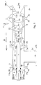
- Fig. 1 shows a longitudinal section through the Kavitatorrohr 1, which consists of several screwed against each other sections, namely the product inlet 2, the Kavitationskonus 3, the discharge chamber 5 and the Axial notebook entry 4, which follow each other in this order in the flow direction 10, the longitudinal direction of the Kavitatorrohrs 1 ,
- the individual pipe sections are conventionally screwed against one another by means of radially outwardly projecting flanges 2 a, b, 3 a, b, 4 a, 5 a, b, c.
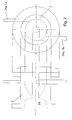
- the discharge chamber 5 has a third flange, since there takes place the product outlet 19 of the medium, that is usually a mixture, radially to the side, as better in Fig. 2 seen.
- this discharge chamber 5 is still closed by the Axial notebook Entry 4, through which the axial rod 7 is guided to the outside, which forms the obstacle trees 9 in the interior 1a in the length range of Kavitationskonus 3 together with the obstacle bodies 8a, b located on it, and which can be adjusted and fixed in the longitudinal direction 10, which happens in the Axial die entry 4.
- the cavitation cone 3 is a substantially straight piece of pipe, but here again the free inner central passage from the beginning of the cavitation cone 3 over about 80% of its length a conical taper to a cross-sectional constriction 21 ', and in this axial constriction section are also in the central free space 1a, the obstacle bodies 8a-e of the obstacle tree 9th
- the interior 1a of the cavitation cone 3 performs a much faster cross-sectional widening 22 ', so that at the end of the cavitation cone 3 the free passage is only slightly smaller than at the beginning of the cavitation cone 3.
- the first two obstacle bodies 8a, b are preferably provided with not only one but two consecutively arranged tear-off edges 23, between which there is a circumferential, concave arc-shaped groove, so that the tear-off edges 23 are viewed in cross-section each form an acute angle.
- the further obstacle bodies 8c-8e are designed as radially outwardly projecting discs of different radius on the axial rod 7, so that between the individual fissure edges 23 of the individual obstacle bodies 8a-8e with respect to the conically narrowing inner wall of the cavitation cone 3 a substantially constant radial Distance as annular gap 18 remains.
- the obstacle bodies 8a-8e are each fixed axially fixed on the axial rod 7 and can only be moved together in the longitudinal direction 10 by means of the axial rod 7.
- another product inlet 3b may be present for a minor component to be admixed.
- This can be as indicated in the cross-sectional constriction of the product inlet 2 or in the formed as a concave baffle front end face of the first obstacle body 8a, in the latter case, then the supply is centrally through the hollow axial rod 7 from the rear end through a pipe.
- the relief chamber 5 is flanged to the cavitation cone 3, which also passes through in the axial direction 10 of the axial rod 7 is, from which the mixture, however, withdrawn in the radial direction through the radially attached outlet nozzle as the outlet opening 19 and is conveyed away.
- the view shows the Fig. 2 of the cavitator in the flow direction that at several product inlets 24b1a and 24b1b in the cross-sectional taper of the product inlet 2 in this tangentially open and are offset from each other so that the réelle meetingsden components have the same direction of rotation.
- Fig. 2 also shows that can connect to the output port 19 of the radial product outlet 19 of the discharge chamber 5 alternatively again a segment in the form of the product inlet 2 ', in turn with the corresponding interior design contour and the described radial product inlets.
- the rear end of the discharge chamber 5 in the axial direction 10 is closed for the product flowing therethrough.
- the axial feedthrough 4 is arranged in the form of a straight piece of pipe with only a flange for flanging on the discharge chamber 5, which has a free diameter corresponding to the thickness of the axial rod 7, the tight, but axially movable, through the cylindrical passage 14 of the axial feedthrough. 4 through and out of the rear end is led out.
- this inner circumference of the axial passage 4 is axially spaced via a respective annular seal, in this case at the rear end of an O-ring seal and at the front, the discharge chamber 5 facing side, a lip seal 16, sealed.
- annular space 18 in the form of an annular recess formed in the passage 14 in the axial distance therebetween in the inner periphery of the passage 14 in which cleaning lines 17a, b supplied from the outside of the axial duct 4 open over the circumference, via which a cleaning agent, for example steam, can be supplied continuously or at certain time intervals for cleaning purposes.
- a cleaning agent for example steam
- a clamping cone 25 is used, which can be biased axially relative to the Axial notebook arrangement 4 by means of screwing. Since the clamping cone 25 also has an axial passage opening corresponding to the thickness of the axial rod 7, thereby the set axial position of the axial rod 7 is fixed by clamping the clamping cone 25 between the axial rod 7 and the axial feedthrough 4.
- Fig. 1 shows further that all inner corners 13a, b, ... are formed in the interior 1a of the Kavitatorrohrs 1 strongly rounded, to avoid the formation of calming zones of the medium to be passed there and thus the deposition and nucleation by longer-term whereabouts of medium in these inner corners. For the same reason, the transitions 12 between the individual obstacle bodies and the axial rod 7 are also formed strongly rounded.
- the corresponding flanges 2a, b, ..., 4a are not welded to the pipe sections, but integrally together with them at least in the individually manufactured for the cavitator sections product inlet 2, cavitation cone 3 and axial feedthrough 4 educated.
- the discharge chamber 5 is usually a purchased part, since it is a simple T-piece of a pipe connection.
- These mass produced Tees are usually made by welding the flanges on the pipe sections, however, in such a large-scale production, the non-porous aftertreatment of welds is possible, so that pore-free welded tees are commercially available. Otherwise, this element would have to be made from scratch.
Abstract
Description
Die Erfindung betrifft einen hydrodynamischen Kavitationsmischer.The invention relates to a hydrodynamic cavitation mixer.
Bekanntermaßen wird mit derartigen Mischern eine Suspension oder Emulsion mit geringem Aufwand und ohne mechanisch angetriebene Teile hergestellt, indem in der dahinströmenden Flüssigkeit zunächst dampfgefüllte Gasblasen erzeugt werden, die anschließend implosionsartig wieder zusammenbrechen.As is known, with such mixers, a suspension or emulsion is produced with little effort and without mechanically driven parts, by initially generating vapor-filled gas bubbles in the liquid flowing along, which subsequently collapse again in an implosion-like manner.
Wenn dieses Zusammenbrechen einer großen Anzahl von Blasen, der so genannten Kavitationsblasen, in der Nähe der Grenzfläche zwischen zwei Phasenbereichen, also etwa großen Öltröpfchen in Wasser, geschieht, wird dadurch die zweite Komponente, in diesem Fall die Öltröpfchen, in kleinere Einheiten zerrissen und dadurch eine sehr feine Vermischung der beiden Komponenten und damit eine sehr stabile Suspension oder Emulsion erzeugt.When this collapse of a large number of bubbles, the so-called cavitation bubbles, occurs near the interface between two phase regions, say large oil droplets in water, the second component, in this case the oil droplets, is torn into smaller units and thereby a very fine mixing of the two components and thus produces a very stable suspension or emulsion.
Die Erzeugung der Kavitationsblasen geschieht in einer strömenden Flüssigkeit durch einen Abfall des statischen Druckes unter den Dampfdruck der Flüssigkeit, wodurch sich dampfgefüllte Gasblasen bilden, z. B. aufgrund einer Stromeinengung.The generation of cavitation bubbles is done in a flowing liquid by a drop in the static pressure below the vapor pressure of the liquid, thereby forming vapor-filled gas bubbles, eg. B. due to a current narrowing.
Wenn anschließend der statische Druck durch eine Aufweitung des Strömungsquerschnitts wieder zunimmt und der statische Druck wieder den Dampfdruck übersteigt, brechen die Gasblasen zusammen.When the static pressure then increases again due to a widening of the flow cross-section and the static pressure again exceeds the vapor pressure, the gas bubbles collapse.
Der statische Druck wird bei Wasser null oder negativ, wenn die Strömungsgeschwindigkeit einen bestimmten, von Umgebungsbedingungen abhängigen Wert, z. B. an den Abrisskanten etwa 14 m/sec., überschreitet.The static pressure becomes zero or negative in the case of water when the flow velocity reaches a certain value dependent on environmental conditions, e.g. B. at the trailing edges about 14 m / sec., Exceeds.
Die Einengung und anschließende Aufweitung des Strömungsquerschnitts kann erreicht werden, indem in einer Durchflusskammer ein Hinderniskörper angeordnet wird, wobei der verbleibende Spalt z. B. zwischen Hinderniskörper und umgebendem Gehäuse der Durchflusskammer die Engstelle bildet.The constriction and subsequent expansion of the flow cross section can be achieved by an obstacle body is arranged in a flow chamber, wherein the remaining gap z. B. between obstacle body and surrounding housing of the flow chamber forms the bottleneck.
Durch mehrfache Anordnung solcher Hinderniskörper hintereinander, aus Platzgründen vorzugsweise in Form von quer zur Strömungsrichtung stehenden Scheiben, wird der Kavitationseffekt vervielfacht, besondern indem in Strömungsrichtung die Ringspaltfläche von einer Scheibe zur nächsten jeweils abnimmt.By multiple arrangement of such obstacle bodies behind each other, for reasons of space preferably in the form of transverse to the flow direction discs, the cavitation effect is multiplied, special in the flow direction, the annular gap area decreases from one disc to the next respectively.
Zusätzlich entstehen dabei zu dem ersten, sich im Ringspaltbereich ausbildenden, Kavitationsfeld ergänzende Kavitationsfelder in den durchströmbaren Hohlräumen zwischen den Hinderniskörpern, und durch die räumliche Überlagerung der einzelnen Kavitationsfelder entsteht ein so genanntes Super-Kavitationsfeld, was eine Vervielfachung der Kavitationswirkung jedes einzelnen Kavitationsfeldes bewirkt.In addition, cavitation fields forming in the cavities field form in the cavities between the obstacle bodies, and the spatial superposition of the individual cavitation fields creates a so-called super-cavitation field, which causes a multiplication of the cavitation effect of each individual cavitation field.
Die Verkleinerung der Ringspaltfläche in Durchströmungsrichtung wird z. B. bewirkt durch einen in Druckströmungsrichtung kleiner werdenden Querschnitt des Kavitatorrohres und einen insbesondere analog kleiner werdenden Durchmesser des Hindernisbäumchens, also der Hinderniskörper auf der Axialstange, sowie die axiale Verschiebbarkeit des gesamten Hindernisbäumchens relativ zum Kavitatorrohr, indem die Axialstange des Hindernisbäumchens axial aus einer geschlossen Stirnseite des Kavitatorrohres herausgeführt wird und dort axial verstellt werden kann.The reduction of the annular gap area in the direction of flow is z. B. caused by a decreasing in the pressure flow direction cross section of the Kavitatorrohres and a particular smaller analog diameter obstacle, so the obstacle body on the axial rod, and the axial displacement of the entire Obstisbäumchens relative to Kavitatorrohr by the Axialstange of Obstacle tree axially from a closed end the Cavitatorrohres is led out and can be adjusted axially there.
Wenn es sich bei der zu bearbeitenden Emulsion oder Suspension um ein Lebensmittel handelt, oder aus anderen Gründen hygienische Zustände unbedingt eingehalten werden müssen, ergeben sich zusätzliche Probleme:If the emulsion or suspension to be processed is a foodstuff, or if it is necessary to comply with hygienic conditions for other reasons, additional problems arise:
Wird das Kavitatorrohr aus mehreren Einzelteilen zusammengesetzt, vor allem in axialer Richtung aneinander anschließenden Einzelteilen, aber auch aus zwei in Längsrichtung geteilten Halbschalen, so müssen dazwischen Dichtungen angeordnet werden, die zwischen Dichtung und umgebenden Material kleinste Hohlräume belassen, in denen sich Keime sammeln und vermehren können. Zusätzlich müssen die miteinander zu verbindenden, meist zu verschraubenden, Einzelteile dicht und möglichst hohlraumfrei aneinander passen, um diese Möglichkeiten für die Verkeimung soweit als möglich zu verringern.If the Kavitatorrohr composed of several individual parts, especially in the axial direction adjoining individual parts, but also from two split in the longitudinal half shells, so must be arranged between gaskets that leave between seal and surrounding material smallest cavities in which collect and multiply germs can. In addition, the individual parts which are to be joined together, usually to be screwed, must fit tightly against one another and as cavity-free as possible in order to reduce these possibilities of contamination as far as possible.
Wird das Kavitatorrohr dagegen aus möglichst wenigen, insbesondere einem einzigen Stück hergestellt, so ist entweder der Herstellungsaufwand sehr hoch oder die Montage des darin anzuordnenden Hindernisbäumchens nicht möglich bzw. sehr aufwendig.On the other hand, if the cavitator tube is made from as few as possible, in particular a single piece, then either the production effort is very high or the assembly of the obstacle tree to be arranged therein is not possible or very expensive.
Werden die einzelnen Abschnitte des Kavitatorrohres nachträglich mit Flanschteilen verschweißt, mit denen die einzelnen Abschnitte des Kavitatiorrohres später gegeneinander verschraubt werden können, so können je nach Unterteilung des Kavitatorrohres die Schweißnähte zwischen Flanschteil und eigentlichem Rohrabschnitt nicht nachbehandelt, insbesondere verschliffen oder auf andere Art und Weise die Schweißnähte geglättet werden mangels Zugänglichkeit im verschweißten Zustand. Dadurch entsteht wiederum das Risiko von in der Schweißnaht verbleibenden, zum Innenraum des Kavitatorrohres offenen Poren, die wiederum als Ablagerungsstätte und Vermehrungsstätte für Keime dienen können.If the individual sections of the Kavitatorrohres welded later with flange, with which the individual sections of Kavitatiorrohres can be screwed against each other later, so depending on the subdivision of Kavitatorrohres the welds between the flange and actual pipe section not treated, in particular sanded or other ways the Welds are smoothed for lack of accessibility in the welded state. This in turn creates the risk of remaining in the weld, the interior of the Kavitatorrohres open pores, which in turn can serve as a deposit site and propagation for germs.
Zusätzlich verlängert das Anschweißen von Flanschen die Gesamtlänge des Kavitatorrohres und damit zwangsweise auch die Länge des Hindernisbäumchens, welches jedoch ohnehin hinsichtlich seiner Stabilität auf Grund der hohen im Betrieb auftretenden Kräfte immer bereits an der Stabilitätsgrenze liegt.In addition, the welding of flanges extends the total length of the Kavitatorrohres and thus forcibly also the length of the Obstisbäumchens, which, however, anyway in terms of its stability Reason the high forces occurring in the operation is always already at the stability limit.
Sofern sich die Schweißnähte in Bereichen befinden, in denen lediglich laminare Strömungen während des Betriebs des Kavitators herrschen, werden diese Bereiche durch die Strömung des Mediums nicht optimal selbst gereinigt.If the welds are in areas in which only laminar flows prevail during operation of the cavitator, these areas are not optimally self-cleaned by the flow of the medium.
Es ist daher die Aufgabe gemäß der Erfindung, einen Kavitator zu schaffen, der einfach und kostengünstig herzustellen ist und dennoch die gestellten Hygieneanforderungen erfüllt.It is therefore the object of the invention to provide a cavitator, which is simple and inexpensive to manufacture and yet meets the stated hygiene requirements.
Diese Aufgabe wird durch die Merkmale des Anspruches 1 gelöst. Vorteilhafte Ausführungsformen ergeben sich aus den Unteransprüchen.This object is solved by the features of
Dadurch, dass das Kavitatorrohr aus einzelnen Abschnitten, insbesondere getrennten Abschnitten für Produkteinlauf, Kavitationskonus und AxialstangenDurchführung in Fließrichtung hintereinander besteht, können die an diesen einzelnen Rohrabschnitten angeordneten Schweißnähte vor dem Zusammenflanschen gut erreicht werden und die Schweißnähte nachbearbeitet werden, insbesondere verschliffen werden oder auf andere Art und Weise der Oberfläche der Schweißnaht zum Innenraum des Kavitators hin beseitigt werden.Characterized in that the Kavitatorrohr consists of individual sections, in particular separate sections for product inlet, Kavitationskonus and AxialstangenDurchführung in the flow direction one behind the other, arranged on these individual pipe sections welds can be achieved before Zusammenflanschen well and the welds are reworked, in particular sanded or otherwise and manner of the surface of the weld to be eliminated to the interior of the cavitator out.
Vorzugsweise werden die Befestigungsflansche an diesen einzelnen Rohrabschnitten jedoch nicht angeschweißt sondern einstückig zusammen mit diesen Rohrabschnitten aus dem Vollen gefertigt, insbesondere aus dem Vollen gedreht, so dass gar keine Schweißnähte entstehen, die die beschriebenen Problemen aufwerfen können.Preferably, however, the Befestigungsfla n cal are not welded to these individual pipe sections but made in one piece with these pipe sections from the solid, in particular turned from solid, so that no welds arise that can raise the problems described.
Die Entlastungskammer, die den radial abfließenden Produktauslauf enthält, ist dabei ein als Zukaufteil beschafftes T-Stück, welches somit zwar in der Regel eine Schweißnaht zwischen dem radialen Rohrstück und dem in Längsrichtung verlaufenden Rohrstück besitzen kann, diese Schweißnaht jedoch vom Hersteller porenfrei nachbehandelt wurde, was bei einer Massenfertigung und spezialisierten Vorrichtungen möglich ist. An die axialen Enden dieses T-Rohrstückes werden die benötigten Flansche angeschweißt und die Schweißnähte nachbehandelt zum Verschließen von Poren.The discharge chamber, which contains the radially outflowing product outlet, is a purchased as a purchased part tee, which thus may indeed have a weld between the radial pipe section and extending in the longitudinal direction pipe section, but this weld was pore-free treated by the manufacturer, which is possible in mass production and specialized devices. At the axial ends of this T-tube piece, the required flanges are welded and the welds aftertreated to close pores.
Zwischen den einzelnen Rohrabschnitten, die vorzugsweise durch Verschrauben der Flansche axial gegeneinander fixiert werden, werden spaltfreie Dichtungen, insbesondere so genannte Keimfrei-Dichtungen, eingesetzt, die das Ablagern von Keimen mangels vorhandener Resträume zwischen Dichtung und umgebenden Material und auch in der Dichtung verhindern.Between the individual pipe sections, which are preferably fixed axially against each other by screwing the flanges, gap-free seals, in particular so-called germ-free seals, are used, which prevent the deposition of germs for lack of residual space between seal and surrounding material and in the seal.
Dabei empfiehlt sich die Anordnung von Dichtungen in solcher Art und Weise, dass die Hauptströmungsrichtung nicht mit der Richtung der Dichtungen zusammenfällt, also die Dichtungen vorzugsweise in Umfangsrichtung bzw. radialer Querrichtung der Hauptströmungsrichtung angeordnet werden, und somit die einzelnen Abschnitte, aus denen das Kavitatorrohr besteht, sich in axialer Richtung aneinander anschließen.In this case, the arrangement of seals is recommended in such a manner that the main flow direction does not coincide with the direction of the seals, so the seals are preferably arranged in the circumferential direction or radial transverse direction of the main flow direction, and thus the individual sections of which the Kavitatorrohr consists , connect to each other in the axial direction.
Ebenfalls um Ablagerungen zu vermeiden und die Selbstreinigungseffekte beim Betrieb des Kavitators zu verbessern, werden am Hindernisbäumchen, die Übergänge zwischen den Hinderniskörpern und der sie tragenden Axialstange gerundet ausgeführt, insbesondere mit einem Rundungsradius von wenigstens 1 mm, besser mindestens 10 mm, und ebenso alle Innenkanten, insbesondere ringförmigen Innenkanten, an den Innenflächen des Kavitators, insbesondere die Innenkanten zwischen zylindrischen und konischen Abschnitten des Kavitators.Also, to avoid deposits and to improve the self-cleaning effects in the operation of the cavitator, the Obstisbäumchen, the transitions between the obstacle bodies and the axial bar carrying them executed rounded, in particular with a radius of curvature of at least 1 mm, better at least 10 mm, and also all inner edges , In particular annular inner edges, on the inner surfaces of the cavitator, in particular the inner edges between cylindrical and conical sections of the cavitator.
Ein unter hygienischen Gesichtspunkten sehr kritischer Bereich ist weiterhin die Durchführung der Axialstange durch das stirnseitig geschlossene Ende des Kavitatorrohres, nämlich den Abschnitt der Axialstangendurchführung.A very critical area from a hygienic point of view is still the passage of the axial rod through the front end of the closed Kavitatorrohres, namely the portion of the Axialstangendurchführung.
Der Ringspalt zwischen der Axialstange und dem aufnehmenden, umgebenden Bauteil wird dabei vorzugsweise mit einer spaltfreien, insbesondere keimfreien, Dichtung wie etwa einer Lippendichtung abgedichtet und nur im einfachen Fall von einer O-Ring-Dichtung.The annular gap between the axial rod and the receiving, surrounding component is preferably sealed with a gap-free, in particular germ-free, seal such as a lip seal and only in the simple case of an O-ring seal.
Um dennoch dort sich bildende Keime entfernen zu können, ohne den Kavitator zerlegen zu müssen, mündet in dem Bereich der Stangendurchführung durch das Gehäuse hindurch in dem Ringspalt eine oder besser zwei einander gegenüberliegende Reinigungsleitungen, durch welche ein Reinigungsfluid, beispielsweise Dampf, in den Ringspalt zu- und abgeführt werden kann und dadurch dort gebildete Keime abtötet.In order nevertheless to be able to remove there forming germs without having to disassemble the cavitator, in the region of the rod passage through the housing in the annular gap opens one or better two opposing cleaning lines, through which a cleaning fluid, such as steam, in the annular gap - And can be dissipated and thereby kills germs formed there.
Stromaufwärts und stromabwärts der Mündungen der Reinigungsleitungen wird dieser Ringsspalt durch entsprechende Dichtungen abgedichtet.Upstream and downstream of the mouths of the cleaning lines of this annular gap is sealed by appropriate seals.
Der Produkteinlauf erfolgt vorzugsweise für die Hauptkomponente in axialer Richtung durch eine entsprechende Öffnung im Produkteinlauf, wobei die zuzusetzenden Komponenten mit geringerem Mengenanteil als die Hauptkomponente vorzugsweise über entsprechende radial mündende Zufuhrleitungen im Produkteinlauf zugeführt werden, und vorzugsweise in oder noch vor der ersten Querschnittsverengung im Abschnitt des Produkteinlaufes.The product inlet preferably takes place for the main component in the axial direction through a corresponding opening in the product inlet, wherein the components to be added are supplied at a lower proportion than the main component preferably via corresponding radially outflowing supply lines in the product inlet, and preferably in or before the first cross-sectional constriction in the section of product enema.
Durch die Ausbildung des ersten Hinderniskörpers als Prallplatte, also mit einer der Strömungsrichtung der ersten Komponente ein möglichst starkes Hindernis bietende, Prallfläche, die eben oder sogar gegen die anströmende erste Komponente konkav ausgebildet ist, kann alternativ auch durch diesen ersten Hinderniskörper hindurch im Gegenstrom die zweite Komponente zugeführt werden, so dass die beiden Komponenten im Bereich an oder unmittelbar vor der Prallfläche allein schon durch den Aufprall der ersten Komponente auf die Prallplatte stark vermischen.By forming the first obstacle body as a baffle plate, so with one of the flow direction of the first component as strong a obstacle bidding, baffle, which is even or concave against the onflowing first component, alternatively by this first obstacle body through countercurrent second Component be supplied so that the two components in the area at or immediately before the Already by the impact of the first component, the impact surface should be strongly mixed with the baffle plate.
Anstelle des Herstellens eines Gemisches kann ein bereits bestehendes Gemisch mit einer analogen Vorrichtung zum Zwecke des Stabilisierens bearbeitet werden, indem dann anstelle der ersten Komponente das zu stabilisierende Gemisch zugeführt wird, und keine weitere Komponente darüber hinaus zugeführt wird, somit auch keine Eingangsöffnung für die zweite Komponente sowie eine hierfür zuführende Rohrleitung benötigt wird.Instead of preparing a mixture, an already existing mixture may be processed with an analogous device for the purpose of stabilization, by then supplying the mixture to be stabilized instead of the first component, and no further component being supplied beyond, thus also no inlet opening for the second Component as well as a supply piping is needed.
Der Aufprall und das Vermischen ist deswegen besonders stark mischend, weil über den ersten Hinderniskörper hinaus, der Strömungsrichtung der ersten Komponente entgegen ragend, keine Halterung der Strömung entgegensteht, denn dieser erste wie auch die folgenden Hinderniskörper können an einer insbesondere in Form einer zentralen Achse ausgebildeten Halterung, die sich von der Gegenrichtung, also entgegen der Strömungsrichtung der ersten Komponente, annähert, im Zentrum der Durchflusskammer gehalten werden.The impact and the mixing is therefore particularly strong mixing, because beyond the first obstacle body, the flow direction of the first component counteracting, no support the flow is opposed, because this first as well as the following obstacle bodies can be formed on a particular in the form of a central axis Holder, which approaches from the opposite direction, ie opposite to the flow direction of the first component, are held in the center of the flow chamber.
Indem die erste Komponente in Strömungsrichtung nach der Eingangsöffnung zunächst eine Querschnittsverengung und anschließend eine Querschnittsaufweitung, beide vorzugsweise jeweils konusförmig, durchläuft, wird durch die Querschnittsaufweitung ein Unterdruck mittels der ersten Komponente in der Durchflusskammer vor der Prallplatte erzeugt, der die zugeführte zweite Komponente in die Durchflusskammer hineinsaugt und zusätzlich die Durchmischung verbessert.By the first component in the flow direction after the inlet opening first a cross-sectional constriction and then a cross-sectional expansion, both preferably in a cone shape, passes through the cross-sectional expansion, a negative pressure generated by the first component in the flow chamber in front of the baffle plate, which supplies the second component into the flow chamber sucked in and also improves the mixing.
Ein hinsichtlich seiner Fläche kleiner werdender Durchflussspalt gemessen in Hauptströmungsrichtung, also der Strömungsrichtung sowohl der ersten Komponente allein als auch des Gemisches ab der Zuführung der zweiten Komponente, kann besonders in Kombination mit dem Aufprall der ersten Komponente auf dem ersten Hinderniskörper dadurch erzielt werden, dass die Hinderniskörper in ihrem Querschnitt in Hauptströmungsrichtung abnehmen und damit auch die Länge des Ringspalters um die Hinderniskörper herum, und damit einen in Strömungsrichtung schmaler werdenden Konus bilden.A smaller in terms of its area flow gap measured in the main flow direction, ie the flow direction of both the first component alone and the mixture from the supply of the second component, can be achieved in particular in combination with the impact of the first component on the first obstacle body that the Remove obstacle body in its cross section in the main flow direction and so that the length of the annular gap around the obstacle body around, and thus form a narrowing in the flow direction cone.
Dabei kann die Wandung des umgebenden Gehäuses parallel zu dem Konus der Hinderniskörper verlaufen oder sogar stärker kegelig ausgebildet sein (größerer Winkel an der Kegelspitze), was den Effekt der abnehmenden Ringfläche noch vergrößert. Aber auch eine schwächere Kegelform (geringerer Winkel) an der Spitze des Kegels des Gehäuses ist möglich, was den durch die Kegelform der Hinderniskörper bewirkten Effekt etwas abschwächt.In this case, the wall of the surrounding housing can run parallel to the cone of the obstacle body or even be formed more conical (larger angle at the apex of the cone), which further increases the effect of the decreasing annular surface. But also a weaker cone shape (lesser angle) at the top of the cone of the housing is possible, which weakens the effect caused by the conical shape of the obstacle body somewhat.
Die konkav ausgebildete Prallfläche bewirkt - vor allem bei mehr oder weniger zentrischem Auftreffen der ersten Komponente auf der Prallplatte und auch zentrischen Zuführen der zweiten Komponente - eine etwa torusförmige Verwirbelung des Gemisches und dadurch eine erneute Annäherung des von der Prallfläche abgeprallten Gemisches an die Prallfläche, wo das Gemisch durch die wiederum auftreffende erste Komponente zusätzlich erneut durchgemischt wird.The concavely formed impact surface causes - above all with more or less centric impingement of the first component on the baffle plate and centric feeding of the second component - an approximately toroidal turbulence of the mixture and thereby a new approach of the rebounded from the baffle mixture to the baffle, where the mixture is additionally mixed again by the again impinging first component.
Der Effekt kann noch verbessert werden, indem die Zuführung der zweiten Komponente auf der Prallfläche des ersten Hinderniskörpers nicht zentral, sondern dezentral an mehreren Eingangsöffnungen ringförmig um das Zentrum der Prallfläche herum verteilt erfolgt, und das Auftreffen der ersten Komponente dafür zentral verbleibt.The effect can be further improved by the supply of the second component on the baffle of the first obstacle body is not distributed centrally, but decentralized distributed at several input openings annularly around the center of the baffle, and the impact of the first component remains central.
Die zentrale Achse zur Fixierung der Hinderniskörper kann dabei gleichzeitig hohl als Rohrleitung zum Zuführung der zweiten Komponente auf die Prallfläche benutzt werden.The central axis for fixing the obstacle body can be used at the same time hollow as a pipe for feeding the second component to the baffle.
Die Wirkung der Querschnittsaufweitung und der Verwirbelung ist umso besser, wenn zwischen der Querschnittsaufweitung und der Prallplatte eine Strecke mit etwa konstantem Querschnitt des Gehäuses liegt, um auf dieser Strecke die Druckverhältnisse über den Querschnitt in der ersten Komponente stabilisieren zu lassen.The effect of cross-sectional expansion and turbulence is all the better when between the cross-sectional expansion and the baffle plate is a distance of approximately constant cross-section of the housing in order to stabilize the pressure conditions over the cross section in the first component on this route.
Das hergestellte Gemisch wird über eine Ausgangsöffnung abgeführt, die vorzugsweise radial, insbesondere in Form eines radialen Ringspaltes, aus dem Gehäuse herausfliesst.The mixture produced is discharged via an outlet opening, which flows out of the housing preferably radially, in particular in the form of a radial annular gap.
Die Effizienz der Vorrichtung, die in der Regel in eine bestehende Rohrleitung eingesetzt wird, lässt sich steigern, indem - beispielsweise in Abhängigkeit der Fließgeschwindigkeit im zuführenden Rohr, der Viskosität der einzelnen Komponenten und deren Mischbarkeit - die Hinderniskörper axial verstellt werden, und zwar in ihrem Abstand zueinander und/oder gruppenweise oder gar insgesamt relativ zum umgebenden Gehäuse, wodurch bei einem kegelförmigen Gehäuse auch das Absolutmaß der Ringspaltflächen verändert wird.The efficiency of the device, which is usually used in an existing pipeline, can be increased by - for example, depending on the flow rate in the feeding tube, the viscosity of the individual components and their miscibility - the obstacle bodies are axially adjusted, in their Distance to each other and / or in groups or even total relative to the surrounding housing, whereby in a conical housing and the absolute size of the annular gap surfaces is changed.
Weiterhin ist es vorteilhaft, wenn die Hinderniskörper zum einen plattenförmig sind, um die Herstellung zu vereinfachen und zu verbilligen, und insbesondere so dünn ausgebildet sind, dass sie an ihren freien Kanten in Strömungsrichtung schwingen können, was das Erzeugen und Abreißen von Dampfblasen erleichtert.Furthermore, it is advantageous if the obstacle bodies are on the one hand plate-shaped in order to simplify and reduce production, and in particular are made so thin that they can oscillate at their free edges in the direction of flow, which facilitates the generation and tearing off of vapor bubbles.
Ebenso wird diese Entwicklung erleichtert durch eine möglichst scharfkantige Ausbildung der Abrisskanten der Hinderniskörper, also z. B. der Platten.Likewise, this development is facilitated by a possible sharp-edged formation of the trailing edges of the obstacle body, ie z. B. the plates.
Der Durchflussspalt zwischen Hinderniskörpern und Gehäuse kann bei z. B. runden Hinderniskörpern, also Scheiben, der radiale Spalt zwischen der freien außen umlaufenden Kante der Scheiben und dem umgebenden Gehäuse sein.The flow gap between obstacle bodies and housing can at z. B. round obstacle bodies, ie discs, the radial gap between the free outer peripheral edge of the discs and the surrounding housing.
Es sind jedoch auch andere Ausbildungen möglich, bei denen beispielsweise die plattenförmigen Hinderniskörper an ihrem radial äußersten Punkt durchaus das Gehäuse erreichen und dort mit diesem verbunden sind, aber beispielsweise nicht über den gesamten Umfang, sondern nur segmentweise, und in den Segmenten dazwischen radial verlaufende Schlitze oder Spalte vorhanden sind, die in axialer Richtung zueinander von einem Hinderniskörper zum nächsten versetzt sein können und als Durchflussspalte dienen.However, other embodiments are possible in which, for example, the plate-shaped obstacle body at its radially outermost point quite reach the housing and are connected to this, but not for example over the entire circumference, but only in segments, and in the segments between radially extending slots or gaps are present, which can be offset from each other in the axial direction from one obstacle body to the next and serve as flow-through gaps.
Die Bildung von Dampfblasen und damit das Auftreten der Kavitation wird ferner gefördert durch eine möglichst große Länge der Abrisskanten.The formation of vapor bubbles and thus the occurrence of cavitation is further promoted by the largest possible length of the fouling edges.
Zu diesem Zweck können gerade bei scheibenförmigen Hinderniskörpern mit dem Umfang als Abrisskante diese durch gewellte oder gezackte Ausbildung in ihrer Länge vergrößert werden, wobei der ungerade Verlauf entweder bei Betrachtung in Axialrichtung oder in Querrichtung hierzu oder in beide Richtungen vorhanden sein kann.For this purpose, especially in the case of disk-shaped obstacle bodies with the circumference as a spoiler lip, these can be increased in their length by corrugated or jagged formation, wherein the odd course can be present either in axial direction or in transverse direction thereto or in both directions.
Falls die ungerade, also gewellte oder gezackte, Form sich bei Betrachtung in Axialrichtung erschließt, kann auch das umgebende Gehäuse - betrachtet in axialer Richtung - analog ausgebildet sein, so dass über den gesamten Umfang ein jeweils gleich bleibender Querschnitt zwischen Gehäuse und Abrisskante eingehalten wird, oder das Gehäuse ist innen durchgehend rund ausgebildet, so dass in Umfangsrichtung die Abstände zur Abrisskante wechseln.If the odd, so wavy or jagged shape opens up when viewed in the axial direction, and the surrounding housing - viewed in the axial direction - may be formed analogously, so that over the entire circumference a respective constant cross section between the housing and spoiler edge is met or the housing is formed inside continuously round, so that change in the circumferential direction, the distances to the trailing edge.
Wenn zusätzlich die Vorrichtung so gestaltet ist, dass in deren Betrieb bestimmte strömungstechnische Bedingungen eingehalten werden, ist der Kavitationseffekt besonders ausgeprägt:In addition, if the device is designed so that in their operation certain flow conditions are met, the cavitation effect is particularly pronounced:
So sollte die Querschnittsverengung nach der Eingangsöffnung so bemessen sein, dass die Fließgeschwindigkeit an der engsten Stelle der Querschnittsverengung der Fließgeschwindigkeit im Durchflussspalt des letzten Hinderniskörpers entspricht. Demgegenüber sollte die Fließgeschwindigkeit dahinter, am Auslass nach dem letzten Hinderniskörper, etwas höher liegen als im Durchflussspalt beim letzten Hinderniskörper.Thus, the cross-sectional constriction should be dimensioned after the inlet opening so that the flow velocity at the narrowest point of the cross-sectional constriction corresponds to the flow velocity in the flow gap of the last obstacle body. In contrast, the flow rate behind it, at the outlet after the last obstacle body, should be slightly higher than in the flow gap at the last obstacle body.
Eine besonders einfache Ausführungsform ist dann gegeben, wenn als Hinderniskörper runde Scheiben mit in Strömungsrichtung gleich bleibendem Durchmesser verwendet werden, und der abnehmende Ringspalt erzielt wird, indem sich das Gehäuse in Hauptdurchflussrichtung verjüngt. Allerdings ist dieser Effekt weniger stark als bei kegelförmig kleiner werdenden Hinderniskörpern, insbesondere Scheiben.A particularly simple embodiment is provided when round disks with a diameter that remains the same in the flow direction are used as obstacle bodies, and the decreasing annular gap is achieved by the housing tapering in the main flow direction. However, this effect is less pronounced than with conically smaller obstacle bodies, in particular slices.
Besonders vorteilhaft ist weiterhin eine starke Querschnittsverengung nach der Eingangsöffnung, so dass sich von der Eingangsöffnung bis zur engsten Stelle der Querschnittsverengung die Fließgeschwindigkeit um den Faktor 9 - 13, insbesondere um den Faktor 10 - 12, insbesondere um den Faktor 10,5 - 11,5, erhöht.Furthermore, a strong cross-sectional constriction downstream of the inlet opening is particularly advantageous, so that the flow velocity increases by a factor of 9-13, in particular by a factor of 10.sup.-12, in particular by a factor of 10.5-11, from the inlet opening to the narrowest point of the cross-sectional constriction. 5, increased.
Vorteilhaft ist ferner, wenn die Hinderniskörper zueinander und/oder zu dem umgebenden Gehäuse so positioniert und dimensioniert werden, dass sich die Fließgeschwindigkeit im Durchflussspalt beim letzten Hinderniskörper in Strömungsrichtung verglichen zu dem Durchgangsspalt beim ersten Hinderniskörper um den Faktor 1,8 - 2,5, insbesondere um 2,0 - 2,3, erhöht.It is also advantageous if the obstacle bodies are positioned and dimensioned relative to one another and / or to the surrounding housing in such a way that the flow velocity in the flow gap at the last obstacle body in the flow direction is 1.8 to 2.5 compared to the passage gap for the first obstacle body. in particular increased by 2.0 - 2.3.
Gleiches gilt, wenn erreicht wird, dass die Fließgeschwindigkeit vom einen zum nächsten Hinderniskörper im jeweiligen Durchgangsspalt jeweils um den Faktor 1,1 - 1,4 zunimmt.The same applies if it is achieved that the flow velocity increases from one to the next obstacle body in the respective passage gap by a factor of 1.1 - 1.4 in each case.
Als optimales Verhältnis zwischen einfacher Bauform und hoher Effizienz der Vorrichtung hat sich eine Anzahl von Hinderniskörpern zwischen 3 und 10, insbesondere zwischen 5 und 7, herausgestellt.As the optimal ratio between simple design and high efficiency of the device, a number of obstacle bodies between 3 and 10, in particular between 5 and 7, has been found.
Wenn bei Scheiben aus Metall, insbesondere aus Edelstahl, die Dicke zwischen 1 und 4 mm, insbesondere zwischen 2 und 3 mm, beträgt, ist die Herstellung sehr einfach, insbesondere kann dabei noch eine im rechten Winkel zur Hauptebene der Platten stehende Schneidkante verwendet werden, und die Platten sind dennoch ausreichend elastisch.If the thickness is between 1 and 4 mm, in particular between 2 and 3 mm, in the case of metal disks, in particular made of stainless steel, the production is very simple, in particular a cutting edge standing at right angles to the main plane of the plates can be used. and the plates are still sufficiently elastic.
Der axiale Abstand von Mitte zu Mitte zweier benachbarter Hinderniskörper sollte dabei zwischen dem Zweifachen und dem Siebenfachen der Dicke der Platten betragen, insbesondere das Dreifache bis Fünffache.The axial distance from center to center of two adjacent obstacle body should be between two and seven times the thickness of the plates, in particular three times to five times.
Die radiale Breite des Ringspaltes zwischen dem Außenumfang der plattenförmigen Hinderniskörper und dem Gehäuse sollte dabei zwischen 1 und 5 mm, insbesondere zwischen 1,5 und 3,8 mm, betragen.The radial width of the annular gap between the outer circumference of the plate-shaped obstacle body and the housing should be between 1 and 5 mm, in particular between 1.5 and 3.8 mm.
Darüber hinaus hat sich eine axiale Länge der Strecke mit konstantem Querschnitt des Gehäuses zwischen der Querschnittsaufweitung und der Prallplatte von einem 0,7 - 1,4-fachen des Durchmessers nach der Querschnittsaufweitung, also des konstanten Querschnitts, als vorteilhaft erwiesen.Moreover, an axial length of the constant cross-section of the housing between the cross-sectional expansion and the baffle plate of 0.7 to 1.4 times the diameter after cross-sectional expansion, that is, the constant cross-section, has been found to be advantageous.
Ebenso sollte der innere freie Durchmesser nach der Querschnittsaufweitung, also auf der Strecke mit konstantem Querschnitt zwischen dem 0,9-fachen und 2,0-fachen, insbesondere zwischen dem 0,9-fachen und 1,1-fachen, des freien Querschnitts der zu- und/oder abführenden Rohrleitung betragen.Likewise, the inner free diameter after the cross-sectional expansion, so on the route with a constant cross section between 0.9 and 2.0 times, in particular between 0.9 and 1.1 times, the free cross section of supply and / or discharge piping amount.
Vorzugsweise wird dabei vor allem der erste, als Prallplatte ausgebildete, Hinderniskörper, ggf. auch der zweite Hinderniskörper, eine wesentlich größere Erstreckung in axialer Richtung aufweisen als die übrigen, eher plattenförmigen Hinderniskörper. Diese in axialer Richtung dickeren ersten Hinderniskörper weisen vorzugsweise an ihrem Außenumfang eine ringförmig umlaufende konkave Einbuchtung auf, so dass sie jeweils zwei ringförmig umlaufende, axial beabstandete Abrisskanten besitzen, wobei die Einbuchtung mindestens der Größe der radialen Breite des Ringspaltes entsprechen sollte, vorzugsweise einem Vielfachen dieses Spaltes.Preferably, in particular, the first obstacle body formed as a baffle plate, possibly also the second obstacle body, will have a substantially greater extent in the axial direction than the remaining, rather plate-shaped obstacle bodies. These thicker in the axial direction first obstacle body preferably have on its outer circumference on an annular circumferential concave indentation, so that they each have two annular circumferential, axially spaced Abrisskanten, the indentation should correspond to at least the size of the radial width of the annular gap, preferably a multiple of this gap.
Die Abrisskanten wirken dann besonders gut, wenn sie im Querschnitt betrachtet einen spitzen Winkel von weniger als 60°, insbesondere weniger als 50° oder gar 45°, besitzen und damit besonders scharf sind.The demolition edges are particularly effective when viewed in cross-section have an acute angle of less than 60 °, in particular less than 50 ° or even 45 °, and thus are particularly sharp.
Dabei soll bevorzugt die in Hauptströmungsrichtung erste Abrisskante des ersten Hinderniskörpers noch im Bereich des konstanten Innendurchmessers des Gehäuses liegen, und nur die zweite sowie alle folgenden Abrisskanten sich bereits im axialen Bereich des sich verjüngenden Innendurchmessers des Gehäuses liegen.In this case, the first tear-off edge of the first obstacle body in the main flow direction should preferably still be in the range of the constant inner diameter of the housing, and only the second and all following tear-off edges are already in the axial region of the tapering inner diameter of the housing.
Insgesamt sollte die Vorrichtung so dimensioniert und gestaltet sein, dass sich über die Gesamtlänge der Vorrichtung ein Druckabfall von 2,5 - 6 bar, insbesondere von 5 - 6 bar, einstellt.Overall, the device should be dimensioned and designed so that over the entire length of the device, a pressure drop of 2.5 - 6 bar, in particular from 5 - 6 bar adjusts.
Für die Verfügbarkeit in Längsrichtung können mehrere Hinderniskörper zu einer Gruppe zusammengefasst und nur gemeinsam in Längsrichtung entlang der zentralen Achse verlagerbar sein, vor allem im Bereich der letzten Hinderniskörper, was den baulichen Aufwand reduziert, die Effizienz aber nur untergeordnet verschlechtert.For availability in the longitudinal direction, a plurality of obstacle bodies can be combined to form a group and can only be displaced together along the central axis in the longitudinal direction, in particular in the area of the last obstacle bodies, which reduces the structural complexity but only subordinately degrades the efficiency.
Ausführungsformen gemäß der Erfindung sind im Folgenden beispielhaft näher beschrieben. Es zeigen:
- Fig. 1:
- den Kavitator im Längsschnitt und
- Fig. 2:
- den Kavitator betrachtet in Fließrichtung.
- Fig. 1:
- the cavitator in longitudinal section and
- Fig. 2:
- the cavitator viewed in the flow direction.
Die einzelnen Rohrstücke sind konventionell mittels radial von diesen nach außen vorstehenden Flansche 2a,b, 3a,b, 4a, 5a,b,c gegeneinander verschraubt. Dabei weist die Entlastungskammer 5 einen dritten Flansch auf, da dort der Produktauslauf 19 des Mediums, also in der Regel eines Gemisches, radial zur Seite stattfindet, wie besser in
In axialer Richtung wird diese Entlastungskammer 5 dennoch verschlossen durch die Axialdurchführung 4, durch welche hindurch die Axialstange 7 nach außen geführt wird, die zusammen mit den auf ihr befindlichen Hinderniskörpern 8a,b das Hindernisbäumchen 9 im Innenraum 1a im Längenbereich des Kavitationskonus 3 bildet, und welche in Längsrichtung 10 verstellt und fixiert werden kann, was in der Axialdurchführung 4 geschieht.In the axial direction, this
In Längsrichtung 10 beginnend stellt der Produkteinlauf 2 ein im wesentlich gerades Rohrstück dar, in dessen zentrale Öffnung, in
Der rotationssymmetrische Innenquerschnitt dieses Produkteinlaufes 2 verengt sich zunächst konusförmig zu einer Querschnittsverengung 21 hin, und vollzieht danach eine noch schnellere Querschnittsaufweitung 22, so dass der freie innere Querschnitt am Ende des Produkteinlaufes 2 dem am Anfang, der Eingangsöffnung 24, entspricht.The rotationally symmetrical inner cross-section of this
Zwischen der Querschnittsaufweitung 22 und dem Ende des Produkteinlaufes 2 befindet sich eine Strecke mit gleich bleibendem freien inneren Querschnitt, die etwa 20 - 30% der Länge des Produkteinlaufes 2 beträgt, und sich auch in den anschließenden Kavitationskonus 3 hinein noch etwas fortsetzen kann.Between the cross-sectional widening 22 and the end of the
An den Produkteinlauf 2 ist der so genannte Kavitationskonus 3 angeflanscht, und die Fuge dazwischen ist über eine Keimfreidichtung 20 abgedichtet, wie dies zwischen allen Komponenten des Kavitatorrohres 1 der Fall ist.At the
Auch der Kavitationskonus 3 ist ein im Wesentlichen gerades Rohrstück, jedoch vollzieht auch hier der freie innere zentrale Durchlass vom Beginn des Kavitationskonus 3 über etwa 80% seiner Länge eine konusförmige Verjüngung bis zu einer Querschnittsverengung 21', und in diesem axialen Verengungsabschnitt befinden sich auch im zentralen freien Innenraum 1a die Hinderniskörper 8a-e des Hindernisbäumchens 9.Also, the
Anschließend vollzieht der Innenraum 1a des Kavitationskonus 3 eine sehr viel schnellere Querschnittsaufweitung 22', so dass am Ende des Kavitationskonus 3 der freie Durchlass nur geringfügig kleiner ist als am Anfang des Kavitationskonus 3.Subsequently, the interior 1a of the
Dabei sind die ersten beiden Hinderniskörper 8a,b vorzugsweise mit in axialer Richtung 10 nicht nur einer, sondern zwei hintereinander angeordneten Abrisskanten 23 ausgestattet, zwischen denen sich eine umlaufende, vom Querschnitt her konkav bogenförmige, Nut befindet, so dass die Abrisskanten 23 im Querschnitt betrachtet jeweils einen spitzen Winkel bilden.In this case, the first two
Die weiteren Hinderniskörper 8c - 8e sind als radial nach außen ragende Scheiben mit unterschiedlichem Radius an der Axialstange 7 ausgebildet, so dass zwischen den einzelnen Abrisskanten 23 der einzelnen Hinderniskörper 8a - 8e gegenüber der sich konusförmig verengenden Innenwandung des Kavitationskonus 3 ein im Wesentlichen gleich bleibender radialer Abstand als Ringspalt 18 verbleibt.The
In diesem Fall sind die Hinderniskörper 8a - 8e jeweils axial fest auf der Axialstange 7 befestigt und können nur gemeinsam in Längsrichtung 10 mittels der Axialstange 7 bewegt werden.In this case, the
Bei diesem Kavitator kann ein weiterer Produkteinlauf 3b für eine zuzumischende Minder-Komponente vorhanden sein. Dieser kann sich wie angedeutet in der Querschnittsverengung des Produkteinlaufes 2 befinden oder auch in der als konkave Prallplatte ausgebildeten vorderen Stirnfläche des ersten Hinderniskörpers 8a, wobei in letzterem Fall dann die Zuführung zentral durch die hohle Axialstange 7 von deren hinterem Ende her durch eine Rohrleitung erfolgt.In this cavitator, another
In Durchflussrichtung 10 ist an den Kavitationskonus 3 die Entlastungskammer 5 angeflanscht, die in axialer Richtung 10 ebenfalls von der Axialstange 7 durchsetzt ist, aus der das Gemisch jedoch in radialer Richtung durch den radial angesetzten Ausgangsstutzen als Ausgangsöffnung 19 abgezogen und abgefördert wird.In the
Dabei zeigt die Ansicht der
Dieser zusätzliche Produkteinlauf 2' kann unter anderem dazu benutzt werden, um für spezielle Anwendungen den Kavitator auch mit einer umgekehrten Fließrichtung zu betreiben, was jedoch nicht Gegenstand der vorliegenden Beschreibung ist.This additional product inlet 2 'can be used, inter alia, to operate the cavitator also with a reverse flow direction for special applications, but this is not the subject of the present description.
Das in axialer Richtung 10 hintere Ende der Entlastungskammer 5 ist für das hindurchfließende Produkt verschlossen. Dort ist die Axialdurchführung 4 in Form eines ebenfalls geraden Rohrstückes mit nur einem Flansch zum Anflanschen an der Entlastungskammer 5 angeordnet, die einen freien Durchmesser entsprechend der Dicke der Axialstange 7 aufweist, die dicht, jedoch axial beweglich, durch die zylindrische Durchführung 14 der Axialdurchführung 4 hindurch und aus deren hinteren Ende herausgeführt wird.The rear end of the
Zur Abdichtung dieser Durchführung 14 ist dieser Innenumfang der Axialdurchführung 4 axial beabstandet über jeweils eine Ringdichtung, in diesem Fall am hinteren Ende eine O-Ringdichtung und an der vorderen, der Entlastungskammer 5 zugewandten Seite, eine Lippendichtung 16, abgedichtet.To seal this passage 14, this inner circumference of the
Um das Ansammeln von Keimen etc. im Raum dazwischen und auch im Bereich der Dichtungen zu vermeiden bzw. diese anschließend abtöten und beseitigen zu können ist im axialen Abstand dazwischen im Innenumfang der Durchführung 14 ein Ringraum 18 in Form einer ringförmigen Vertiefung in der Durchführung 14 ausgebildet, in der von der Außenseite der Axialdurchführung 4 zugeführte Reinigungsleitungen 17a,b über den Umfang verteilt münden, über die ein Reinigungsmittel, beispielsweise Dampf, kontinuierlich oder in bestimmten Zeitabständen zu Reinigungszwecken zugeführt werden kann.In order to avoid the accumulation of germs, etc. in the space between and in the area of the seals or to kill and eliminate them is an
Hinter der Durchführung 14 weitet sich der Innenraum der Axialdurchführung 4 konusförmig auf und in diesen ist ein Klemmkonus 25 eingesetzt, der axial gegenüber der Axialdurchführung 4 mittels Verschraubung vorgespannt werden kann. Da der Klemmkonus 25 ebenfalls eine axiale Durchgangsöffnung entsprechend der Dicke der Axialstange 7 aufweist, wird hierdurch die eingestellte Axialposition der Axialstange 7 durch Verklemmen des Klemmkonus 25 zwischen Axialstange 7 und der Axialdurchführung 4 fixiert.Behind the passage 14, the interior of the
Um Ablagerungen in Poren von Schweißnähten zu vermeiden, sind wenigstens bei den individuell für den Kavitator hergestellten Abschnitten Produkteinlauf 2, Kavitationskonus 3 und Axialdurchführung 4 die entsprechenden Flansche 2a,b,..., 4a nicht an den Rohrstücken verschweißt, sondern einstückig zusammen mit diesen ausgebildet.In order to avoid deposits in pores of welds, the corresponding
Die Entlastungskammer 5 ist dagegen meist ein Zukaufteil, da es sich um ein einfaches T-Stück einer Rohrverbindung handelt. Diese in Großserie hergestellten T-Stücke sind zwar meist durch Schweißen der Flansche an den Rohrstücken hergestellt, jedoch ist bei einer solchen großtechnischen Herstellung die porenfreie Nachbehandlung von Schweißnähten möglich, so dass porenfrei geschweißte T-Stücke im Handel verfügbar sind. Ansonsten müsste auch dieses Element aus dem Vollen hergestellt werden.The
- 11
- KavitatorrohrKavitatorrohr
- 1 a1 a
- Innenrauminner space
- 2, 2'2, 2 '
- Produkteinlaufproduct inlet
- 2a,b2a, b
- Befestigungsflanschmounting flange
- 3a,b3a, b
- Befestigungsflanschmounting flange
- 33
- KavitationskonusKavitationskonus
- 4a,b4a, b
- Befestigungsflanschmounting flange
- 44
- Axialdurchführungaxial passage
- 5a,b5a, b
- Befestigungsflanschmounting flange
- 55
- Entlastungskammerrelief chamber
- 6a,b6a, b
- SchweißnahtWeld
- 77
- AxialstangeAxial rod
- 8a,b8a, b
- Hinderniskörperobstacle body
- 99
- Hindernisbäumchenobstacle trees
- 1010
- Längsrichtung, FließrichtungLongitudinal direction, flow direction
- 1111
- Querrichtungtransversely
- 1212
- Übergangcrossing
- 13a,b13a, b
- Inneneckeinside corner
- 1414
- Durchführungexecution
- 1515
- O-RingO-ring
- 1616
- Lippendichtunglip seal
- 17a,b17a, b
- Reinigungsleitungcleaning line
- 1818
- Ringspaltannular gap
- 1919
- Ausgangsöffnungoutput port
- 2020
- Keimfrei-DichtungSterile seal
- 21, 21'21, 21 '
- QuerschnittsverengungCross-sectional narrowing
- 2222
- QuerschnittsaufweitungSectional widening
- 2323
- Abrisskantetear-off edge
- 2424
- Eingangsöffnungentrance opening
- 2525
- Klemmkonusclamping cone
Claims (16)
das Kavitatorrohr (1) aus einzelnen, insbesondere axialen, Rohrabschnitten zusammengeflanscht ist und insbesondere wenigstens die Rohrabschnitte Produkteinlauf (2), Kavitationskonus (3) und Axialdurchführung (4) Einzelteile, insbesondere Drehteile, sind.Tubular cavitator for mixing or for stabilizing at least two components flowing through, of which at least one is liquid, by means of a hydrodynamic cavitation field, with
the Kavitatorrohr (1) from individual, in particular axial, pipe sections is flanged together and in particular at least the pipe sections product inlet (2), Kavitationskonus (3) and axial feedthrough (4) items, in particular rotating parts are.
dadurch gekennzeichnet, dass
die Befestigungsflansche (2a, b, 3a,b, 4a) an den Rohrabschnitten Produkteinlauf (2), Kavitationskonus (3), Axialdurchführung (4) ohne Schweißnaht aus dem Vollen mitgefertigt, insbesondere mitgedreht sind.Cavitator according to claim 1,
characterized in that
the mounting flanges (2a, b, 3a, b, 4a) on the pipe sections product inlet (2), cavitation cone (3), axial feedthrough (4) without weld welded from the solid, in particular rotated.
dadurch gekennzeichnet, dass
die Entlastungskammer (5) ein T-Rohrstück mit angeschweißten Flanschen (5a,b, c) und nachbearbeiteten Schweißnähten (6a,b,c) zum Verschließen von Poren in der Schweißnaht (6a,b,c) sind.Cavitator according to one of the preceding claims,
characterized in that
the relief chamber (5) is a T-tube piece with welded-on flanges (5a, b, c) and reworked welds (6a, b, c) for closing pores in the weld seam (6a, b, c).
dadurch gekennzeichnet, dass
characterized in that
dadurch gekennzeichnet, dass
characterized in that
dadurch gekennzeichnet, dass
characterized in that
dadurch gekennzeichnet, dass
dass die Produkteinlauföffnungen (3b) für die Minder-Komponente im Produkteinlaufrohr (2) in oder stromaufwärts der Verengung des Innenraumes (1a) tangential und in die gleiche Umfangsrichtung weisend mündet.Cavitator according to one of the preceding claims,
characterized in that
in that the product inlet openings (3b) for the under-component in the product inlet pipe (2) opens tangentially and in the same circumferential direction in or upstream of the narrowing of the interior space (1a).
dadurch gekennzeichnet, dass
characterized in that
dadurch gekennzeichnet, dass
characterized in that
dadurch gekennzeichnet, dass
characterized in that
dadurch gekennzeichnet, dass
characterized in that
dadurch gekennzeichnet, dass
die Hinderniskörper (8a, ...) runde Scheiben sind mit in Hauptströmungsrichtung (10) abnehmendem Durchmesser und insbesondere die Gehäusewandung in immer dem gleichen radialen Abstand zu den radialen Außenkanten der Scheiben verläuft.Cavitator according to one of the preceding claims,
characterized in that
the obstacle bodies (8a,...) are circular disks with a diameter decreasing in the main flow direction (10) and in particular the housing wall is always at the same radial distance from the radial outer edges of the disks.
dadurch gekennzeichnet, dass
characterized in that
dadurch gekennzeichnet, dass
characterized in that
dadurch gekennzeichnet, dass
characterized in that
dadurch gekennzeichnet, dass
der Kavitator so gestaltet ist, dass im Betrieb des Kavitators sich ein Druckabfall von 2,5 - 6 bar, besser 5 - 6 bar, einstellt.Cavitator according to one of the preceding claims,
characterized in that
the cavitator is designed so that during operation of the cavitator, a pressure drop of 2.5 - 6 bar, better 5 - 6 bar, adjusts.
Applications Claiming Priority (2)
| Application Number | Priority Date | Filing Date | Title |
|---|---|---|---|
| DE202008008254 | 2008-06-19 | ||
| DE202008009204U DE202008009204U1 (en) | 2008-06-19 | 2008-07-09 | cavitator |
Publications (2)
| Publication Number | Publication Date |
|---|---|
| EP2135667A1 true EP2135667A1 (en) | 2009-12-23 |
| EP2135667B1 EP2135667B1 (en) | 2010-12-08 |
Family
ID=39736811
Family Applications (1)
| Application Number | Title | Priority Date | Filing Date |
|---|---|---|---|
| EP09163116A Not-in-force EP2135667B1 (en) | 2008-06-19 | 2009-06-18 | Cavitator |
Country Status (3)
| Country | Link |
|---|---|
| EP (1) | EP2135667B1 (en) |
| AT (1) | ATE490815T1 (en) |
| DE (2) | DE202008009204U1 (en) |
Cited By (3)
| Publication number | Priority date | Publication date | Assignee | Title |
|---|---|---|---|---|
| US9732068B1 (en) | 2013-03-15 | 2017-08-15 | GenSyn Technologies, Inc. | System for crystalizing chemical compounds and methodologies for utilizing the same |
| DE102018105138B3 (en) | 2018-03-06 | 2019-06-27 | Egm-Holding-International Gmbh | cavitator |
| DE202022102005U1 (en) | 2022-04-13 | 2022-05-23 | Cvt Gmbh & Co. Kg | Device for purifying water and system for purifying water |
Families Citing this family (4)
| Publication number | Priority date | Publication date | Assignee | Title |
|---|---|---|---|---|
| DE102013102593B4 (en) * | 2013-03-14 | 2019-05-23 | Cavitatorsystems Gmbh Mediale Mischsysteme & Anlagen | Method for adjusting the flow of a cavitation mixer for a hygienically produced fluid mixture |
| EP3187257A1 (en) * | 2015-12-29 | 2017-07-05 | AVARUS Suisse Holding AG | Cavitation reactor device for treating flowable substances |
| RU197014U1 (en) * | 2018-05-07 | 2020-03-24 | Федеральное государственное бюджетное образовательное учреждение высшего образования Нижегородская государственная сельскохозяйственная академия (ФГБОУ ВО Нижегородская ГСХА) | Vortex cavitator for presowing seed treatment |
| WO2020124263A1 (en) * | 2018-12-21 | 2020-06-25 | Nanorial Technologies Ltd. | Apparatus, methods, and systems for mixing, dispersing substances |
Citations (5)
| Publication number | Priority date | Publication date | Assignee | Title |
|---|---|---|---|---|
| FR1381821A (en) * | 1964-02-04 | 1964-12-14 | Ultrasonics Ltd | Process and atomizer device for the production of aerosols or other intimate mixtures of liquids and gases |
| EP1359997A2 (en) * | 2000-11-20 | 2003-11-12 | Five Star Technologies, Inc. | A device and method for creating hydrodynamic cavitation in fluids |
| US20060050608A1 (en) * | 2004-09-07 | 2006-03-09 | Kozyuk Oleg V | Device and method for creating hydrodynamic cavitation in fluids |
| EP1780176A1 (en) * | 2005-10-25 | 2007-05-02 | Wagner, Manfred | Disinfection by cavitation |
| US20070205307A1 (en) * | 2006-03-03 | 2007-09-06 | Kozyuk Oleg V | Device and method for creating hydrodynamic cavitation in fluids |
-
2008
- 2008-07-09 DE DE202008009204U patent/DE202008009204U1/en not_active Expired - Lifetime
-
2009
- 2009-06-18 DE DE502009000223T patent/DE502009000223D1/en active Active
- 2009-06-18 EP EP09163116A patent/EP2135667B1/en not_active Not-in-force
- 2009-06-18 AT AT09163116T patent/ATE490815T1/en active
Patent Citations (5)
| Publication number | Priority date | Publication date | Assignee | Title |
|---|---|---|---|---|
| FR1381821A (en) * | 1964-02-04 | 1964-12-14 | Ultrasonics Ltd | Process and atomizer device for the production of aerosols or other intimate mixtures of liquids and gases |
| EP1359997A2 (en) * | 2000-11-20 | 2003-11-12 | Five Star Technologies, Inc. | A device and method for creating hydrodynamic cavitation in fluids |
| US20060050608A1 (en) * | 2004-09-07 | 2006-03-09 | Kozyuk Oleg V | Device and method for creating hydrodynamic cavitation in fluids |
| EP1780176A1 (en) * | 2005-10-25 | 2007-05-02 | Wagner, Manfred | Disinfection by cavitation |
| US20070205307A1 (en) * | 2006-03-03 | 2007-09-06 | Kozyuk Oleg V | Device and method for creating hydrodynamic cavitation in fluids |
Cited By (3)
| Publication number | Priority date | Publication date | Assignee | Title |
|---|---|---|---|---|
| US9732068B1 (en) | 2013-03-15 | 2017-08-15 | GenSyn Technologies, Inc. | System for crystalizing chemical compounds and methodologies for utilizing the same |
| DE102018105138B3 (en) | 2018-03-06 | 2019-06-27 | Egm-Holding-International Gmbh | cavitator |
| DE202022102005U1 (en) | 2022-04-13 | 2022-05-23 | Cvt Gmbh & Co. Kg | Device for purifying water and system for purifying water |
Also Published As
| Publication number | Publication date |
|---|---|
| DE202008009204U1 (en) | 2008-09-04 |
| EP2135667B1 (en) | 2010-12-08 |
| DE502009000223D1 (en) | 2011-01-20 |
| ATE490815T1 (en) | 2010-12-15 |
Similar Documents
| Publication | Publication Date | Title |
|---|---|---|
| EP1749564B1 (en) | Stabilizer for mixing or stabilizing a mixture in a hydrodynamic cavitation field | |
| EP2135667B1 (en) | Cavitator | |
| EP1780176B1 (en) | Disinfection by cavitation | |
| EP1924346B1 (en) | Mixing element for the inversion and mixture of flowing materials in a flow channel, as well as kit and mixer comprising such mixing elements | |
| EP1891390B1 (en) | Device for influencing the flow in the region of a tube support plate of a tubular heat exchanger | |
| DE102011007003B4 (en) | Bernoulli filter and method for filtering liquids | |
| DE102010047782B3 (en) | Flow rectifier for closed pipes | |
| DE3717128C2 (en) | ||
| EP1945337A1 (en) | Eddy chamber | |
| EP1604162B1 (en) | Tube bundle heat exchanger | |
| DE102014009015A1 (en) | Mixing device of an exhaust gas purification system of a motor vehicle internal combustion engine | |
| DE3123873C2 (en) | Device for mixing treatment medium into a suspension | |
| WO2016062610A1 (en) | Jet pump | |
| EP2382435B1 (en) | Tube bundle heat exchanger with device for influencing the flow in the area of a pipe manifold plate | |
| DE1776175B1 (en) | REMOVABLE HEAT EXCHANGER | |
| WO2005013715A2 (en) | Steam injection module for heating pumped products | |
| DE102011082702A1 (en) | Nozzle assembly for cleaning inside surfaces of hollow chamber of e.g. bottle, has outlet openings distributed in circumferential direction of housing and laterally arranged at central longitudinal axis of nozzle housing | |
| EP1926539A1 (en) | Cavitation degasifier | |
| DE102013102593B4 (en) | Method for adjusting the flow of a cavitation mixer for a hygienically produced fluid mixture | |
| DE102011106494A1 (en) | Nozzle device, useful in strand guide device that is useful in continuous casting plant for guiding cast strand, comprises nozzle head for atomizing fluid, hydraulic line for supplying fluid to nozzle head, and replaceable tubular insert | |
| EP4286037A2 (en) | Compact mixing device for mixing fluids | |
| EP3189887A1 (en) | Cavitation reactor for treating flowable substances | |
| DE102023108344A1 (en) | Pipeline component and method for conveying a fluid in a pipeline component | |
| DD270813A3 (en) | DEVICE FOR THE HOMOGENEOUS DISTRIBUTION OF A GAS / LIQUID MIXTURE | |
| DE202011052417U1 (en) | Section of a gas flowed pipe |
Legal Events
| Date | Code | Title | Description |
|---|---|---|---|
| PUAI | Public reference made under article 153(3) epc to a published international application that has entered the european phase |
Free format text: ORIGINAL CODE: 0009012 |
|
| AK | Designated contracting states |
Kind code of ref document: A1 Designated state(s): AT BE BG CH CY CZ DE DK EE ES FI FR GB GR HR HU IE IS IT LI LT LU LV MC MK MT NL NO PL PT RO SE SI SK TR |
|
| 17P | Request for examination filed |
Effective date: 20091208 |
|
| 17Q | First examination report despatched |
Effective date: 20100108 |
|
| GRAP | Despatch of communication of intention to grant a patent |
Free format text: ORIGINAL CODE: EPIDOSNIGR1 |
|
| RIC1 | Information provided on ipc code assigned before grant |
Ipc: B01F 5/06 20060101AFI20100624BHEP |
|
| GRAS | Grant fee paid |
Free format text: ORIGINAL CODE: EPIDOSNIGR3 |
|
| GRAA | (expected) grant |
Free format text: ORIGINAL CODE: 0009210 |
|
| AK | Designated contracting states |
Kind code of ref document: B1 Designated state(s): AT BE BG CH CY CZ DE DK EE ES FI FR GB GR HR HU IE IS IT LI LT LU LV MC MK MT NL NO PL PT RO SE SI SK TR |
|
| REG | Reference to a national code |
Ref country code: GB Ref legal event code: FG4D Free format text: NOT ENGLISH |
|
| REG | Reference to a national code |
Ref country code: CH Ref legal event code: EP |
|
| REG | Reference to a national code |
Ref country code: IE Ref legal event code: FG4D |
|
| REF | Corresponds to: |
Ref document number: 502009000223 Country of ref document: DE Date of ref document: 20110120 Kind code of ref document: P |
|
| REG | Reference to a national code |
Ref country code: NL Ref legal event code: VDEP Effective date: 20101208 |
|
| PG25 | Lapsed in a contracting state [announced via postgrant information from national office to epo] |
Ref country code: LT Free format text: LAPSE BECAUSE OF FAILURE TO SUBMIT A TRANSLATION OF THE DESCRIPTION OR TO PAY THE FEE WITHIN THE PRESCRIBED TIME-LIMIT Effective date: 20101208 Ref country code: NO Free format text: LAPSE BECAUSE OF FAILURE TO SUBMIT A TRANSLATION OF THE DESCRIPTION OR TO PAY THE FEE WITHIN THE PRESCRIBED TIME-LIMIT Effective date: 20110308 |
|
| LTIE | Lt: invalidation of european patent or patent extension |
Effective date: 20101208 |
|
| PG25 | Lapsed in a contracting state [announced via postgrant information from national office to epo] |
Ref country code: LV Free format text: LAPSE BECAUSE OF FAILURE TO SUBMIT A TRANSLATION OF THE DESCRIPTION OR TO PAY THE FEE WITHIN THE PRESCRIBED TIME-LIMIT Effective date: 20101208 Ref country code: CY Free format text: LAPSE BECAUSE OF FAILURE TO SUBMIT A TRANSLATION OF THE DESCRIPTION OR TO PAY THE FEE WITHIN THE PRESCRIBED TIME-LIMIT Effective date: 20101208 Ref country code: HR Free format text: LAPSE BECAUSE OF FAILURE TO SUBMIT A TRANSLATION OF THE DESCRIPTION OR TO PAY THE FEE WITHIN THE PRESCRIBED TIME-LIMIT Effective date: 20101208 Ref country code: FI Free format text: LAPSE BECAUSE OF FAILURE TO SUBMIT A TRANSLATION OF THE DESCRIPTION OR TO PAY THE FEE WITHIN THE PRESCRIBED TIME-LIMIT Effective date: 20101208 Ref country code: SI Free format text: LAPSE BECAUSE OF FAILURE TO SUBMIT A TRANSLATION OF THE DESCRIPTION OR TO PAY THE FEE WITHIN THE PRESCRIBED TIME-LIMIT Effective date: 20101208 Ref country code: SE Free format text: LAPSE BECAUSE OF FAILURE TO SUBMIT A TRANSLATION OF THE DESCRIPTION OR TO PAY THE FEE WITHIN THE PRESCRIBED TIME-LIMIT Effective date: 20101208 Ref country code: BG Free format text: LAPSE BECAUSE OF FAILURE TO SUBMIT A TRANSLATION OF THE DESCRIPTION OR TO PAY THE FEE WITHIN THE PRESCRIBED TIME-LIMIT Effective date: 20110308 Ref country code: NL Free format text: LAPSE BECAUSE OF FAILURE TO SUBMIT A TRANSLATION OF THE DESCRIPTION OR TO PAY THE FEE WITHIN THE PRESCRIBED TIME-LIMIT Effective date: 20101208 |
|
| REG | Reference to a national code |
Ref country code: IE Ref legal event code: FD4D |
|
| PG25 | Lapsed in a contracting state [announced via postgrant information from national office to epo] |
Ref country code: EE Free format text: LAPSE BECAUSE OF FAILURE TO SUBMIT A TRANSLATION OF THE DESCRIPTION OR TO PAY THE FEE WITHIN THE PRESCRIBED TIME-LIMIT Effective date: 20101208 Ref country code: IS Free format text: LAPSE BECAUSE OF FAILURE TO SUBMIT A TRANSLATION OF THE DESCRIPTION OR TO PAY THE FEE WITHIN THE PRESCRIBED TIME-LIMIT Effective date: 20110408 Ref country code: GR Free format text: LAPSE BECAUSE OF FAILURE TO SUBMIT A TRANSLATION OF THE DESCRIPTION OR TO PAY THE FEE WITHIN THE PRESCRIBED TIME-LIMIT Effective date: 20110309 Ref country code: CZ Free format text: LAPSE BECAUSE OF FAILURE TO SUBMIT A TRANSLATION OF THE DESCRIPTION OR TO PAY THE FEE WITHIN THE PRESCRIBED TIME-LIMIT Effective date: 20101208 Ref country code: PT Free format text: LAPSE BECAUSE OF FAILURE TO SUBMIT A TRANSLATION OF THE DESCRIPTION OR TO PAY THE FEE WITHIN THE PRESCRIBED TIME-LIMIT Effective date: 20110408 Ref country code: ES Free format text: LAPSE BECAUSE OF FAILURE TO SUBMIT A TRANSLATION OF THE DESCRIPTION OR TO PAY THE FEE WITHIN THE PRESCRIBED TIME-LIMIT Effective date: 20110319 Ref country code: IE Free format text: LAPSE BECAUSE OF FAILURE TO SUBMIT A TRANSLATION OF THE DESCRIPTION OR TO PAY THE FEE WITHIN THE PRESCRIBED TIME-LIMIT Effective date: 20101208 |
|
| PG25 | Lapsed in a contracting state [announced via postgrant information from national office to epo] |
Ref country code: SK Free format text: LAPSE BECAUSE OF FAILURE TO SUBMIT A TRANSLATION OF THE DESCRIPTION OR TO PAY THE FEE WITHIN THE PRESCRIBED TIME-LIMIT Effective date: 20101208 Ref country code: PL Free format text: LAPSE BECAUSE OF FAILURE TO SUBMIT A TRANSLATION OF THE DESCRIPTION OR TO PAY THE FEE WITHIN THE PRESCRIBED TIME-LIMIT Effective date: 20101208 Ref country code: RO Free format text: LAPSE BECAUSE OF FAILURE TO SUBMIT A TRANSLATION OF THE DESCRIPTION OR TO PAY THE FEE WITHIN THE PRESCRIBED TIME-LIMIT Effective date: 20101208 |
|
| PLBE | No opposition filed within time limit |
Free format text: ORIGINAL CODE: 0009261 |
|
| STAA | Information on the status of an ep patent application or granted ep patent |
Free format text: STATUS: NO OPPOSITION FILED WITHIN TIME LIMIT |
|
| PG25 | Lapsed in a contracting state [announced via postgrant information from national office to epo] |
Ref country code: DK Free format text: LAPSE BECAUSE OF FAILURE TO SUBMIT A TRANSLATION OF THE DESCRIPTION OR TO PAY THE FEE WITHIN THE PRESCRIBED TIME-LIMIT Effective date: 20101208 |
|
| 26N | No opposition filed |
Effective date: 20110909 |
|
| PG25 | Lapsed in a contracting state [announced via postgrant information from national office to epo] |
Ref country code: IT Free format text: LAPSE BECAUSE OF FAILURE TO SUBMIT A TRANSLATION OF THE DESCRIPTION OR TO PAY THE FEE WITHIN THE PRESCRIBED TIME-LIMIT Effective date: 20101208 Ref country code: MT Free format text: LAPSE BECAUSE OF FAILURE TO SUBMIT A TRANSLATION OF THE DESCRIPTION OR TO PAY THE FEE WITHIN THE PRESCRIBED TIME-LIMIT Effective date: 20101208 |
|
| BERE | Be: lapsed |
Owner name: CAVITATOR SYSTEMS G.M.B.H. Effective date: 20110630 |
|
| REG | Reference to a national code |
Ref country code: DE Ref legal event code: R097 Ref document number: 502009000223 Country of ref document: DE Effective date: 20110909 |
|
| PG25 | Lapsed in a contracting state [announced via postgrant information from national office to epo] |
Ref country code: BE Free format text: LAPSE BECAUSE OF NON-PAYMENT OF DUE FEES Effective date: 20110630 |
|
| PG25 | Lapsed in a contracting state [announced via postgrant information from national office to epo] |
Ref country code: MK Free format text: LAPSE BECAUSE OF FAILURE TO SUBMIT A TRANSLATION OF THE DESCRIPTION OR TO PAY THE FEE WITHIN THE PRESCRIBED TIME-LIMIT Effective date: 20101208 |
|
| PG25 | Lapsed in a contracting state [announced via postgrant information from national office to epo] |
Ref country code: MC Free format text: LAPSE BECAUSE OF NON-PAYMENT OF DUE FEES Effective date: 20110630 |
|
| PG25 | Lapsed in a contracting state [announced via postgrant information from national office to epo] |
Ref country code: LU Free format text: LAPSE BECAUSE OF NON-PAYMENT OF DUE FEES Effective date: 20110618 |
|
| PG25 | Lapsed in a contracting state [announced via postgrant information from national office to epo] |
Ref country code: TR Free format text: LAPSE BECAUSE OF FAILURE TO SUBMIT A TRANSLATION OF THE DESCRIPTION OR TO PAY THE FEE WITHIN THE PRESCRIBED TIME-LIMIT Effective date: 20101208 |
|
| PG25 | Lapsed in a contracting state [announced via postgrant information from national office to epo] |
Ref country code: HU Free format text: LAPSE BECAUSE OF FAILURE TO SUBMIT A TRANSLATION OF THE DESCRIPTION OR TO PAY THE FEE WITHIN THE PRESCRIBED TIME-LIMIT Effective date: 20101208 |
|
| REG | Reference to a national code |
Ref country code: CH Ref legal event code: PL |
|
| PG25 | Lapsed in a contracting state [announced via postgrant information from national office to epo] |
Ref country code: CH Free format text: LAPSE BECAUSE OF NON-PAYMENT OF DUE FEES Effective date: 20130630 Ref country code: LI Free format text: LAPSE BECAUSE OF NON-PAYMENT OF DUE FEES Effective date: 20130630 |
|
| REG | Reference to a national code |
Ref country code: DE Ref legal event code: R082 Ref document number: 502009000223 Country of ref document: DE Representative=s name: PATENTANWAELTE WEICKMANN & WEICKMANN, DE Ref country code: DE Ref legal event code: R082 Ref document number: 502009000223 Country of ref document: DE Representative=s name: WEICKMANN & WEICKMANN PATENTANWAELTE - RECHTSA, DE Ref country code: DE Ref legal event code: R082 Ref document number: 502009000223 Country of ref document: DE Representative=s name: WEICKMANN & WEICKMANN PATENT- UND RECHTSANWAEL, DE |
|
| REG | Reference to a national code |
Ref country code: FR Ref legal event code: PLFP Year of fee payment: 8 |
|
| REG | Reference to a national code |
Ref country code: DE Ref legal event code: R082 Ref document number: 502009000223 Country of ref document: DE Representative=s name: WEICKMANN & WEICKMANN PATENTANWAELTE - RECHTSA, DE Ref country code: DE Ref legal event code: R081 Ref document number: 502009000223 Country of ref document: DE Owner name: CAVITATORSYSTEMS GMBH MEDIALE MISCHSYSTEME & A, DE Free format text: FORMER OWNER: CAVITATOR SYSTEMS GMBH, 84036 LANDSHUT, DE Ref country code: DE Ref legal event code: R082 Ref document number: 502009000223 Country of ref document: DE Representative=s name: WEICKMANN & WEICKMANN PATENT- UND RECHTSANWAEL, DE |
|
| REG | Reference to a national code |
Ref country code: FR Ref legal event code: PLFP Year of fee payment: 9 |
|
| REG | Reference to a national code |
Ref country code: FR Ref legal event code: PLFP Year of fee payment: 10 |
|
| PGFP | Annual fee paid to national office [announced via postgrant information from national office to epo] |
Ref country code: FR Payment date: 20200623 Year of fee payment: 12 |
|
| PGFP | Annual fee paid to national office [announced via postgrant information from national office to epo] |
Ref country code: GB Payment date: 20200625 Year of fee payment: 12 |
|
| PGFP | Annual fee paid to national office [announced via postgrant information from national office to epo] |
Ref country code: AT Payment date: 20200618 Year of fee payment: 12 |
|
| PGFP | Annual fee paid to national office [announced via postgrant information from national office to epo] |
Ref country code: DE Payment date: 20200819 Year of fee payment: 12 |
|
| REG | Reference to a national code |
Ref country code: DE Ref legal event code: R079 Ref document number: 502009000223 Country of ref document: DE Free format text: PREVIOUS MAIN CLASS: B01F0005060000 Ipc: B01F0025400000 |
|
| REG | Reference to a national code |
Ref country code: DE Ref legal event code: R119 Ref document number: 502009000223 Country of ref document: DE |
|
| REG | Reference to a national code |
Ref country code: AT Ref legal event code: MM01 Ref document number: 490815 Country of ref document: AT Kind code of ref document: T Effective date: 20210618 |
|
| GBPC | Gb: european patent ceased through non-payment of renewal fee |
Effective date: 20210618 |
|
| PG25 | Lapsed in a contracting state [announced via postgrant information from national office to epo] |
Ref country code: GB Free format text: LAPSE BECAUSE OF NON-PAYMENT OF DUE FEES Effective date: 20210618 Ref country code: DE Free format text: LAPSE BECAUSE OF NON-PAYMENT OF DUE FEES Effective date: 20220101 Ref country code: AT Free format text: LAPSE BECAUSE OF NON-PAYMENT OF DUE FEES Effective date: 20210618 |
|
| PG25 | Lapsed in a contracting state [announced via postgrant information from national office to epo] |
Ref country code: FR Free format text: LAPSE BECAUSE OF NON-PAYMENT OF DUE FEES Effective date: 20210630 |