EP1931135A1 - Apparatus and method for correcting shake of image photographing device - Google Patents
Apparatus and method for correcting shake of image photographing device Download PDFInfo
- Publication number
- EP1931135A1 EP1931135A1 EP07122227A EP07122227A EP1931135A1 EP 1931135 A1 EP1931135 A1 EP 1931135A1 EP 07122227 A EP07122227 A EP 07122227A EP 07122227 A EP07122227 A EP 07122227A EP 1931135 A1 EP1931135 A1 EP 1931135A1
- Authority
- EP
- European Patent Office
- Prior art keywords
- optical path
- light
- image
- shake
- changing
- Prior art date
- Legal status (The legal status is an assumption and is not a legal conclusion. Google has not performed a legal analysis and makes no representation as to the accuracy of the status listed.)
- Ceased
Links
Images


Classifications
-
- G—PHYSICS
- G02—OPTICS
- G02B—OPTICAL ELEMENTS, SYSTEMS OR APPARATUS
- G02B27/00—Optical systems or apparatus not provided for by any of the groups G02B1/00 - G02B26/00, G02B30/00
- G02B27/64—Imaging systems using optical elements for stabilisation of the lateral and angular position of the image
- G02B27/646—Imaging systems using optical elements for stabilisation of the lateral and angular position of the image compensating for small deviations, e.g. due to vibration or shake
-
- G—PHYSICS
- G03—PHOTOGRAPHY; CINEMATOGRAPHY; ANALOGOUS TECHNIQUES USING WAVES OTHER THAN OPTICAL WAVES; ELECTROGRAPHY; HOLOGRAPHY
- G03B—APPARATUS OR ARRANGEMENTS FOR TAKING PHOTOGRAPHS OR FOR PROJECTING OR VIEWING THEM; APPARATUS OR ARRANGEMENTS EMPLOYING ANALOGOUS TECHNIQUES USING WAVES OTHER THAN OPTICAL WAVES; ACCESSORIES THEREFOR
- G03B17/00—Details of cameras or camera bodies; Accessories therefor
- G03B17/02—Bodies
- G03B17/17—Bodies with reflectors arranged in beam forming the photographic image, e.g. for reducing dimensions of camera
-
- G—PHYSICS
- G03—PHOTOGRAPHY; CINEMATOGRAPHY; ANALOGOUS TECHNIQUES USING WAVES OTHER THAN OPTICAL WAVES; ELECTROGRAPHY; HOLOGRAPHY
- G03B—APPARATUS OR ARRANGEMENTS FOR TAKING PHOTOGRAPHS OR FOR PROJECTING OR VIEWING THEM; APPARATUS OR ARRANGEMENTS EMPLOYING ANALOGOUS TECHNIQUES USING WAVES OTHER THAN OPTICAL WAVES; ACCESSORIES THEREFOR
- G03B5/00—Adjustment of optical system relative to image or object surface other than for focusing
-
- H—ELECTRICITY
- H04—ELECTRIC COMMUNICATION TECHNIQUE
- H04N—PICTORIAL COMMUNICATION, e.g. TELEVISION
- H04N23/00—Cameras or camera modules comprising electronic image sensors; Control thereof
- H04N23/60—Control of cameras or camera modules
- H04N23/68—Control of cameras or camera modules for stable pick-up of the scene, e.g. compensating for camera body vibrations
- H04N23/681—Motion detection
- H04N23/6812—Motion detection based on additional sensors, e.g. acceleration sensors
-
- H—ELECTRICITY
- H04—ELECTRIC COMMUNICATION TECHNIQUE
- H04N—PICTORIAL COMMUNICATION, e.g. TELEVISION
- H04N23/00—Cameras or camera modules comprising electronic image sensors; Control thereof
- H04N23/60—Control of cameras or camera modules
- H04N23/68—Control of cameras or camera modules for stable pick-up of the scene, e.g. compensating for camera body vibrations
- H04N23/682—Vibration or motion blur correction
- H04N23/685—Vibration or motion blur correction performed by mechanical compensation
- H04N23/687—Vibration or motion blur correction performed by mechanical compensation by shifting the lens or sensor position
-
- G—PHYSICS
- G03—PHOTOGRAPHY; CINEMATOGRAPHY; ANALOGOUS TECHNIQUES USING WAVES OTHER THAN OPTICAL WAVES; ELECTROGRAPHY; HOLOGRAPHY
- G03B—APPARATUS OR ARRANGEMENTS FOR TAKING PHOTOGRAPHS OR FOR PROJECTING OR VIEWING THEM; APPARATUS OR ARRANGEMENTS EMPLOYING ANALOGOUS TECHNIQUES USING WAVES OTHER THAN OPTICAL WAVES; ACCESSORIES THEREFOR
- G03B2205/00—Adjustment of optical system relative to image or object surface other than for focusing
- G03B2205/0007—Movement of one or more optical elements for control of motion blur
- G03B2205/0023—Movement of one or more optical elements for control of motion blur by tilting or inclining one or more optical elements with respect to the optical axis
-
- G—PHYSICS
- G03—PHOTOGRAPHY; CINEMATOGRAPHY; ANALOGOUS TECHNIQUES USING WAVES OTHER THAN OPTICAL WAVES; ELECTROGRAPHY; HOLOGRAPHY
- G03B—APPARATUS OR ARRANGEMENTS FOR TAKING PHOTOGRAPHS OR FOR PROJECTING OR VIEWING THEM; APPARATUS OR ARRANGEMENTS EMPLOYING ANALOGOUS TECHNIQUES USING WAVES OTHER THAN OPTICAL WAVES; ACCESSORIES THEREFOR
- G03B2217/00—Details of cameras or camera bodies; Accessories therefor
- G03B2217/005—Blur detection
Definitions
- the present invention relates generally to an apparatus and a method for correcting a shake of an image photographing device, and more particularly to an apparatus and a method for correcting a shake of an image photographing device, which enables miniaturization and thin-shaping of the image photographing device, and yet can implement an anti-shake function.
- a camera such as a digital camera, a camera module for mounting on a portable appliance (e.g., a cellular phone), etc.
- a portable appliance e.g., a cellular phone
- a camera continues to advance in optical performance to the extent that it has recently been equipped with an auto focusing function, and introducing a zoom lens becomes an important issue for enhancing the performance of a camera. Therefore, it is required to correct a shake occurring according to the introduction of a high magnification zoom.
- OIS optical image stabilizer
- EIS electrical image stabilizer
- DIS digital image stabilizer
- This OIS may be classified into an active prism type, a lens shift type and a sensor movement type, but every type of OIS has a problem in that when it is employed in a camera, a camera barrel becomes complex in structure and large in size. Thus, dissimilar to a digital camera, there are many difficulties in applying the OIS to a camera module for mounting on a portable appliance where importance is attached to miniaturization and thin-shaping of the camera module, rather than shake correction.
- the active prism type OIS is accompanied with an increase in thickness, caused by the addition of an active prism
- the lens shift type OIS is accompanied with complexity in structure, caused by the addition of a component for shifting a lens
- the sensor movement type OIS is accompanied with an increase in thickness, caused by the addition of a component for moving a sensor.
- Japanese Patent Application Laid-open No. 2005-352240 discloses a camera optical system, in which an optical path dividing means is provided, an object to be photographed is incident to a finder optical system after reflected twice, and a camera shake is corrected by changing the tilt angle of one mirror.
- a shake of a camera module for mounting on a portable appliance is corrected without increasing the size of the camera module.
- an object of the present invention is to provide an apparatus and a method for correcting a shake of an image photographing device, which can prevent the thickness of the image photographing device and simultaneously correct a shake of the image photographing device by changing the optical path of light incident to the image photographing device.
- an apparatus for correcting a shake of an image photographing device including: a shake sensing unit sensing the shake of the image photographing device which photographs an image of a subject; a first optical path changing unit changing an optical path of light incident to the image photographing device; an angle adjusting unit adjusting an angle of a light-incident surface of the first optical path changing unit according to the sensed shake; and an image generating unit generating the image of the subject through the light, the optical path of which has been changed by the first optical path changing unit.
- an apparatus for correcting a shake of an image photographing device including: a shake sensing unit sensing the shake of the image photographing device which photographs an image of a subject; a first optical path changing unit changing an optical path of light incident to the image photographing device; an angle adjusting unit adjusting an angle of a light-incident surface of the first optical path changing unit in a first direction according to the sensed shake; and an image generating unit generating the image of the subject by changing a position of an area receiving the light, the optical path of which has been changed by the first optical path changing unit, in a second direction.
- an apparatus for correcting a shake of an image photographing device including: a shake sensing unit sensing the shake of the image photographing device which photographs an image of a subject; a first optical path changing unit changing an optical path of light incident to the image photographing device; a second optical path changing unit changing an optical path, to which the optical path of the light has been changed by the first optical path changing unit, once again; and an image generating unit generating the image of the subject through the light, the optical path of which has been changed again by the second optical path changing unit.
- a method of correcting a shake of an image photographing device including: sensing the shake of the image photographing device which photographs an image of a subject; changing an optical path of light incident to the image photographing device; when the optical path of the light is changed, adjusting an angle of an optical path, to which the optical path of the light is changed, according to the sensed shake; and generating the image of the subject through the light, the optical path of which has been changed.
- a method of correcting a shake of an image photographing device including: sensing the shake of the image photographing device which photographs an image of a subject; changing an optical path of light incident to the image photographing device; when the optical path of the light is changed, adjusting an angle of an optical path, to which the optical path of the light is changed, in a first direction according to the sensed shake; and generating the image of the subject by changing a position of an area receiving the light, the optical path of which has been changed, in a second direction.
- a method of correcting a shake of an image photographing device including: sensing the shake of the image photographing device which photographs an image of a subject; changing an optical path of light incident to the image photographing device; changing the changed optical path of the light once again; and generating the image of the subject through the light, the optical path of which has been changed again.
- These computer program instructions may be stored in a computer-usable or computer-readable memory, capable of being directed to a computer or other programmable data processing equipment, in order to implement such functions in a specific manner, so it is also possible to produce a system including instruction means for executing the functions described in each block or each step of the block diagrams or the flowcharts by means of the instructions stored in the computer-usable or computer-readable memory.
- the computer program instructions may be loaded into a computer or other programmable data processing equipment, it is also possible to provide stages for executing the functions described in each block or each step of the block diagrams or the flowcharts by means of the instructions which operate the computer or other programmable data processing equipment by executing a series of operational stages in the computer or other programmable data processing equipment to generate a computer-executed process.
- each block or each step may represent a part of a module, a segment or a code, including one or more executable instructions for executing a specific logical function or specific logical functions.
- the functions mentioned in the blocks or steps may occur out of order in several alternative embodiments. For example, two blocks or steps shown in succession may be executed substantially concurrently, or may be executed in reverse order according to corresponding functions.
- FIG. 1 is a block diagram illustrating an apparatus for correcting a shake of an image photographing device according to a first preferred embodiment of the present invention
- FIG. 2 is a schematic view illustrating the same.
- the apparatus 100 for correcting a shake of an image photographing device includes a shake sensing unit 110 sensing a shake of the image photographing device which photographs an image of a given subject, a first optical path changing unit 120 changing an optical path of light incident to the image photographing device, an angle adjusting unit 130 adjusting an angle of a light-incident surface (hereinafter referred to as "incident surface") of the first optical path changing unit 120, and an image generating unit 140 generating the image of the subject through light, the optical path of which has been changed by the first optical path changing unit 120.
- a shake sensing unit 110 sensing a shake of the image photographing device which photographs an image of a given subject
- a first optical path changing unit 120 changing an optical path of light incident to the image photographing device
- an angle adjusting unit 130 adjusting an angle of a light-incident surface (hereinafter referred to as "incident surface") of the first optical path changing unit 120
- image generating unit 140 generating the image of the subject through light,
- the shake sensing unit 110 may include a gyro sensor, an acceleration sensor, a terrestrial magnetism sensor, an image analysis algorithm and so forth which are provided in the image photographing device to sense a shake of a user who uses the image photographing device, but the present invention is not limited thereto.
- the image photographing device may include a camera, a portable appliance with a camera module, etc., but the present invention is also not limited thereto.
- the first optical path changing unit 120 may be formed of a prism, a mirror and the like, so that it can change an optical path of light incident through an objective 120a.
- an optical path, to which the optical path of the incident light is changed, can be determined according to an angle of the incident surface, and an angle of the incident surface can be adjusted by the angle adjusting unit 130.
- the angle adjusting unit 130 adjusts an angle of the incident surface in at least one of a first direction and a second direction.
- the first direction will be assumed to be a vertical direction
- the second direction will be assumed to be a horizontal direction
- the vertical direction refers to a direction perpendicular to an optical axis incident onto the objective 120a
- the horizontal direction refers to a direction horizontal to the optical axis incident onto the objective 120a.
- the angle adjusting unit 130 adjusts an angle of the incident surface in the vertical and horizontal directions is merely an example for promoting the understanding of the present invention, and a direction in which an angle of the incident surface is adjusted may vary according to the actual environments where the image photographing device is used.
- an angle of the incident surface of the first optical path changing unit 120 is adjusted in the vertical direction, and the width (t) of the image generating unit 140 corresponds to the thickness of the image photographing device.
- the thickness of image photographing devices in most ordinary cameras extends in a direction horizontal to an optical axis incident onto the objective 120a, and light incident through the objective 120a turns to the vertical direction by the first optical path changing unit 120 and reaches the image generating unit 140 in this embodiment of the present invention, by reason of which it can be understood that the width (t) of the image generating unit 140 corresponds to the thickness of the image photographing device.
- an anti-shake function can be implemented through the first optical path changing unit 120 without increasing the thickness of the image photographing device.
- the angle adjusting unit 130 can determine in which direction an angle of the incident surface of the first optical path changing unit 120 is changed, based on a sensing result from the shake sensing unit 110, and can change the optical path of the incident light by adjusting an angle of the incident surface according to a result of the determination.
- Changing the optical path of the incident light in this way is aimed at correcting a shake occurring while the incident light, the optical path of which has been changed by the first optical path changing unit 120, passes through a variator 120b and a compensator 120c, and reaches the image generating unit 140 provided with an image sensor.
- an optical path, to which the optical path of the incident light is changed by the first optical path changing unit 120 may vary according to the size of the image sensor.
- the positions of the respective lenses 120a, 120b, 120c, as illustrated in FIG. 2 are merely an example for promoting the understanding of the present invention, and may vary according to the type and specification of the image photographing device.
- a VCM Vehicle Coil Module
- a stepping motor a DC/AC motor
- an ultrasonic motor an organic/plastic driver and so forth
- an organic/plastic driver an organic/plastic driver and so forth
- the present invention is not limited thereto.
- FIG. 2 illustrates that the first optical path changing unit 120 adjusts an angle of its incident surface in the vertical direction
- this is merely an example for promoting the understanding of the present invention, and any type of modification may be made to the direction in which an angle of the incident surface is adjusted.
- FIG. 3 is a schematic view illustrating an apparatus for correcting a shake of an image photographing device according to a second preferred embodiment of the present invention.
- the second embodiment of FIG. 3 can be understood as an embodiment where, in the above-mentioned shake correction apparatus of FIGS. 1 and 2 , a shake of the image photographing device is corrected in such a manner that the first optical path changing unit 120 changes an optical path in the first direction, and a position of an image sensor included in the image generating unit 140 is changed in the second direction.
- the first optical path changing unit 120 may be formed of a prism, a mirror and the like, so that it can change an optical path of light incident through an objective 120a.
- an optical path, to which the optical path of the incident light is changed can be determined according to an angle of the incident surface, and an angle of the incident surface can be adjusted by the angle adjusting unit 130.
- the angle adjusting unit 130 can adjust an angle of the incident surface, based on the shake sensed by the shake sensing unit 110, and an optical path, to which the optical path of the incident light is changed, can be determined according to the adjusted angle.
- the image generating unit 140 may include an image sensor 141 receiving light and a driver 142 changing a position of the image sensor 141.
- the driver 142 can correct the shake by changing a position of the image sensor 141 in the second direction.
- a shake component in the first direction that is, the vertical direction
- a shake component in the second direction that is, the horizontal direction
- the directions in which an angle of the incident surface of the first optical path changing unit 120 and a position of the image sensor 141 in the image generating unit 140 may be reversed to each other.
- FIG. 4 is a block diagram illustrating an apparatus for correcting a shake of an image photographing device according to a third preferred embodiment of the present invention
- FIG. 5 is a schematic view illustrating the same.
- the apparatus 100 for correcting a shake of an image photographing device includes a shake sensing unit 110 sensing a shake of the image photographing device which photographs an image of a given subject, a first optical path changing unit 120 changing an optical path of light incident to the image photographing device, a second optical path changing unit 150 changing an optical path, to which the optical path of the incident light has been changed by the first optical path changing unit 120, once again, and a image generating unit 140 generating the image of the subject through light, the optical path of which has been changed again by the second optical path changing unit 150.
- the shake sensing unit 110 may include a gyro sensor, an acceleration sensor, a terrestrial magnetism sensor, an image analysis algorithm and so forth which are provided in the image photographing device to sense a shake of a user who uses the image photographing device, but the present invention is not limited thereto.
- the first optical path changing unit 120 changes an optical path of light, which is incident through the objective 120a, in a direction perpendicular to an optical axis incident onto the objective 120a
- the second optical path changing unit 150 changes on optical path, to which the optical path of the incident light has been changed by the first optical path changing unit 120, once again in a direction horizontal to the optical axis incident onto the objective 120a.
- a light receiving area, at which light arrives in the image generating unit 140 is positioned in a direction perpendicular to the optical axis incident onto the objective 120a. In this case, that is, when the image generating unit 140 is positioned in a direction perpendicular to the ground in this way, a limitation on increasing the width of the image generating unit 140 is relieved.
- the apparatus 100 for correcting a shake of an image photographing device may include an angle adjusting unit 130 capable of adjusting an angle of an incident surface in the first and second optical path changing units 120, 150, respectively.
- This angle adjusting unit 130 can adjust an angle of the incident surface of the first optical path changing unit 120 in the first direction, and adjust an angle of the incident surface of the second optical path changing unit 150 in the second direction, according to a sensing result from the shake sensing unit 110.
- this embodiment of the present invention is described by exemplifying a case where the first and second optical path changing units 120, 150 adjust angles of their incident surfaces in different directions, the present invention is not limited thereto.
- one of the first and second optical path changing units 120, 150 is fixed, and the other adjusts an angle in both the first and second directions, but the present invention is also not limited thereto.
- the first direction corresponds to a vertical direction
- the second direction corresponds to a horizontal direction.
- a position of the image sensor which receives light in the image generating unit 140, may be adjusted in order to correct a shake, in addition to adjusting angles of the incident surfaces of the first and second optical path changing units 120, 150.
- the image generating unit 140 may include the image sensor 141 and a driver 142 changing a position of the image sensor 141.
- the driver 142 can correct a shake by changing a position of the image sensor 141 according to a sensing result from the shake sensing unit 110.
- the image generating unit 140 is disposed in a direction perpendicular to the optical axis incident onto the objective 120a, an increase in the thickness of the image photographing device can be prevented even when the driver 142 changing a position of the image sensor 141 is provided.
- FIG. 7 is a flowchart illustrating a method of correcting a shake of an image photographing device according to the first embodiment of the present invention.
- this method of FIG. 7 can be understood as a method of operating the apparatus described in FIGS. 1 and 2 .
- the method of correcting a shake of an image photographing device begins with sensing a shake, occurring in the image photographing device, by the shake sensing unit 110 (S110).
- the shake sensing unit 110 includes a gyro sensor, an acceleration sensor, a terrestrial magnetism sensor, an image analysis algorithm and so forth, so that it can sense shake occurrence.
- the angle adjusting unit 130 determines in which direction an angle of the incident surface of the first optical path changing unit 120 is adjusted (S120), and adjusts an angle of the incident surface of the first optical path changing unit 120 in the determined direction (S130).
- S120 an angle of the incident surface of the first optical path changing unit 120 is adjusted
- S130 adjusts an angle of the incident surface of the first optical path changing unit 120 in the determined direction
- the first optical path changing unit 120 may adjust an angle of its incident surface in at least one of the first and second directions. For example, if the first direction corresponds to a direction perpendicular to an optical axis incident onto the objective 120a, and the second direction corresponds to a direction horizontal to the optical axis incident onto the objective 120a, as assumed above, the first optical path changing unit 120 can correct the shake occurring in the image photographing device by adjusting an angle of its incident surface in at least one of the vertical and horizontal directions.
- the image generating unit 140 receives light, the optical path of which has been changed by the first optical path changing unit 120, to thereby generate an image of a subject (S140).
- FIG. 8 is a flowchart illustrating a method of correcting a shake of an image photographing device according to the second embodiment of the present invention.
- this method of FIG. 8 can be understood as a method of operating the apparatus described in FIG. 3 .
- the method of correcting a shake of an image photographing device begins with sensing a shake, occurring in the image photographing device, by the shake sensing unit 110 (S210).
- the shake sensing unit 110 includes a gyro sensor, an acceleration sensor, a terrestrial magnetism sensor, an image analysis algorithm and so forth, so that it can sense shake occurrence.
- FIG. 8 by way of example, a description will be given of a case where the shake sensing unit 110 senses both a shake component in the first direction and a shake component in the second direction.
- the first direction corresponds to a direction perpendicular to an optical axis incident onto the objective 120a
- the second direction corresponds to a direction horizontal to the optical axis incident onto the objective 120a.
- FIG. 8 by way of example, a description will also be given of a case where the first optical path changing unit 120 corrects the shake component in the first direction, and the image generating unit 140 corrects the shake component in the second direction.
- the angle adjusting unit 130 adjusts an angle of the incident surface of the first optical path changing unit 120 in the first direction according to the shake component in the first direction among the shake sensed in the shake sensing unit 110 (S220).
- the driver 142 adjusts a position of the image sensor 141 in the second direction according to the shake component in the second direction among the shake sensed in the shake sensing unit 110 (S230).
- the image generating unit 140 generates an image of a subject through light reaching the image sensor 141 (S240).
- FIG. 9 is a flowchart illustrating a method of correcting a shake of an image photographing device according to the third embodiment of the present invention.
- this method of FIG. 8 can be understood as a method of operating the apparatus described in FIGS. 4 to 6 .
- the method of correcting a shake of an image photographing device begins with sensing a shake, occurring in the image photographing device, by the shake sensing unit 110 (S310).
- the shake sensing unit 110 includes a gyro sensor, an acceleration sensor, a terrestrial magnetism sensor, an image analysis algorithm and so forth, so that it can sense shake occurrence.
- the angle adjusting unit 130 corrects the sensed shake by adjusting an angle of the incident surface of the first optical path changing unit 120 in the first direction (S320) and adjusting an angle of the incident surface of the second optical path changing unit 150 in the second direction (S330).
- S320 an angle of the incident surface of the first optical path changing unit 120 in the first direction
- S330 an angle of the incident surface of the second optical path changing unit 150 in the second direction
- the angle adjusting unit 130 may correct the sensed shake by setting one of the incident surfaces of the first and second optical path changing units 120, 150 at a fixed angle and adjusting an angle of the other incident surface.
- the image generating unit 140 generates an image of a subject through light reaching the image sensor 141 (S340).
- the light receiving area, at which light arrives in the image generating unit 140 is positioned in a direction perpendicular to the optical axis incident onto the objective 120a in order that light, the optical path of which is changed twice by the first and second optical path changing units 120, 150, can reach the image sensor 141.
- the image generating unit 140 is positioned perpendicular to the optical axis in this way, the thickness of the image photographing device does not increase even when the width of the image generating unit 140 increases.
- the shake occurring in the image photographing device may be corrected by providing the image generating unit 140 with the driver 142 to change a position of the image sensor 141.
- FIG. 9 the light receiving area, at which light arrives in the image generating unit 140, is positioned in a direction perpendicular to the optical axis incident onto the objective 120a in order that light, the optical path of which is changed twice by the first and second optical path changing units 120, 150, can reach the image sensor 141.
- - unit means a software component or a hardware component such as a FPGA (Field Programmable Gate Array) or an ASIC (Application Specific Integrated Circuit), which performs certain tasks, but is not limited to software or hardware.
- a module may be configured in such a manner as to reside on an addressable storage medium or may be configured in such a manner as to execute one or more processors.
- a module may include, by way of example, components such as software components, object-oriented software components, class components and task components, processes, functions, attributes, procedures, subroutines, segments of program codes, drivers, firmware, microcode, circuitry, data, databases, data architectures, tables, arrays, and variables.
- the functionality provided by the components and modules may be incorporated into fewer components and modules or may be further separated into additional components and modules.
- an optical path of light incident to the image photographing device is appropriately changed through a prism, a mirror and the like, so that an increase in the thickness of the image photographing device can be prevented, and simultaneously an anti-shake function can be implemented.
Abstract
Description
- This application claims priority from
Korean Patent Application No. 10-2006-0121741 filed on December 4, 2006 - The present invention relates generally to an apparatus and a method for correcting a shake of an image photographing device, and more particularly to an apparatus and a method for correcting a shake of an image photographing device, which enables miniaturization and thin-shaping of the image photographing device, and yet can implement an anti-shake function.
- With an increasing demand from consumers, a camera, such as a digital camera, a camera module for mounting on a portable appliance (e.g., a cellular phone), etc., has been more and more miniaturized and thinned over recent years, and its performance has also been improved by leaps and bounds.
- A camera continues to advance in optical performance to the extent that it has recently been equipped with an auto focusing function, and introducing a zoom lens becomes an important issue for enhancing the performance of a camera. Therefore, it is required to correct a shake occurring according to the introduction of a high magnification zoom.
- An optical image stabilizer (OIS), an electrical image stabilizer (EIS) and a digital image stabilizer (DIS) are mainly used for correcting such a shake. Of them, the OIS has the best shake correction performance and is less affected by various limitations on performance.
- This OIS may be classified into an active prism type, a lens shift type and a sensor movement type, but every type of OIS has a problem in that when it is employed in a camera, a camera barrel becomes complex in structure and large in size. Thus, dissimilar to a digital camera, there are many difficulties in applying the OIS to a camera module for mounting on a portable appliance where importance is attached to miniaturization and thin-shaping of the camera module, rather than shake correction.
- For example, the active prism type OIS is accompanied with an increase in thickness, caused by the addition of an active prism, the lens shift type OIS is accompanied with complexity in structure, caused by the addition of a component for shifting a lens, and the sensor movement type OIS is accompanied with an increase in thickness, caused by the addition of a component for moving a sensor.
- Therefore, there is a need for a way to allow a shake of a camera module for mounting on a portable appliance to be corrected without increasing the size of the camera module.
-
Japanese Patent Application Laid-open No. 2005-352240 - Accordingly, the present invention has been made to solve the above-mentioned problems occurring in the prior art, and an object of the present invention is to provide an apparatus and a method for correcting a shake of an image photographing device, which can prevent the thickness of the image photographing device and simultaneously correct a shake of the image photographing device by changing the optical path of light incident to the image photographing device.
- It should be noted that objects of the present invention are not limited to that previously mentioned, and other objects not mentioned herein will be apparent to those skilled in the art from the following description.
- To accomplish the above-mentioned object of the present invention, in accordance with one aspect of the present invention, there is provided an apparatus for correcting a shake of an image photographing device, the apparatus including: a shake sensing unit sensing the shake of the image photographing device which photographs an image of a subject; a first optical path changing unit changing an optical path of light incident to the image photographing device; an angle adjusting unit adjusting an angle of a light-incident surface of the first optical path changing unit according to the sensed shake; and an image generating unit generating the image of the subject through the light, the optical path of which has been changed by the first optical path changing unit.
- In accordance with another aspect of the present invention, there is provided an apparatus for correcting a shake of an image photographing device, the apparatus including: a shake sensing unit sensing the shake of the image photographing device which photographs an image of a subject; a first optical path changing unit changing an optical path of light incident to the image photographing device; an angle adjusting unit adjusting an angle of a light-incident surface of the first optical path changing unit in a first direction according to the sensed shake; and an image generating unit generating the image of the subject by changing a position of an area receiving the light, the optical path of which has been changed by the first optical path changing unit, in a second direction.
- In accordance with yet another aspect of the present invention, there is provided an apparatus for correcting a shake of an image photographing device, the apparatus including: a shake sensing unit sensing the shake of the image photographing device which photographs an image of a subject; a first optical path changing unit changing an optical path of light incident to the image photographing device; a second optical path changing unit changing an optical path, to which the optical path of the light has been changed by the first optical path changing unit, once again; and an image generating unit generating the image of the subject through the light, the optical path of which has been changed again by the second optical path changing unit.
- In accordance with still yet another aspect of the present invention, there is provided a method of correcting a shake of an image photographing device, the method including: sensing the shake of the image photographing device which photographs an image of a subject; changing an optical path of light incident to the image photographing device; when the optical path of the light is changed, adjusting an angle of an optical path, to which the optical path of the light is changed, according to the sensed shake; and generating the image of the subject through the light, the optical path of which has been changed.
- In accordance with still yet another aspect of the present invention, there is provided a method of correcting a shake of an image photographing device, the method including: sensing the shake of the image photographing device which photographs an image of a subject; changing an optical path of light incident to the image photographing device; when the optical path of the light is changed, adjusting an angle of an optical path, to which the optical path of the light is changed, in a first direction according to the sensed shake; and generating the image of the subject by changing a position of an area receiving the light, the optical path of which has been changed, in a second direction.
- In accordance with still yet another aspect of the present invention, there is provided a method of correcting a shake of an image photographing device, the method including: sensing the shake of the image photographing device which photographs an image of a subject; changing an optical path of light incident to the image photographing device; changing the changed optical path of the light once again; and generating the image of the subject through the light, the optical path of which has been changed again.
- Details about other embodiments of the present invention are included in the following detailed description and the accompanying drawings.
- The above and other objects, features and advantages of the present invention will be more apparent from the following detailed description taken in conjunction with the accompanying drawings, in which:
-
FIG. 1 is a block diagram illustrating an apparatus for correcting a shake of an image photographing device in accordance with a first preferred embodiment of the present invention; -
FIG. 2 is a schematic view illustrating the apparatus for correcting a shake of an image photographing device in accordance with the first embodiment of the present invention; -
FIG. 3 is a schematic view illustrating an apparatus for correcting a shake of an image photographing device in accordance with a second preferred embodiment of the present invention; -
FIG. 4 is a block diagram illustrating an apparatus for correcting a shake of an image photographing device in accordance with a third preferred embodiment of the present invention; -
FIG. 5 is a schematic view illustrating first and second optical path changing units in the apparatus for correcting a shake of an image photographing device in accordance with the third embodiment of the present invention; -
FIG. 6 is a schematic view illustrating the first and second optical path changing units, where an angle of an incident surface of light is adjusted, in the apparatus for correcting a shake of an image photographing device in accordance with the third embodiment of the present invention; -
FIG. 7 is a flowchart illustrating a method of correcting a shake of an image photographing device in accordance with the first embodiment of the present invention; -
FIG. 8 is a flowchart illustrating a method of correcting a shake of an image photographing device in accordance with the second embodiment of the present invention; and -
FIG. 9 is a flowchart illustrating a method of correcting a shake of an image photographing device in accordance with the third embodiment of the present invention. - Advantages and features of the present invention, and ways to achieve them will be apparent from embodiments of the present invention described with reference to the accompanying drawings in the following. However, the scope of the present invention is not limited to such embodiments and the present invention may be realized in various forms. The embodiments disclosed in the specification are nothing but examples provided to disclose the present invention and assist those skilled in the art to completely understand the present invention. The present invention is defined only by the scope of the appended claims. Also, the same reference numerals are used to designate the same elements throughout the specification and drawings.
- Hereinafter, preferred embodiments of the present invention will be described in detail with reference to the accompanying block diagrams and flowcharts for explaining an apparatus and a method for correcting a shake of an image photographing device. Here, it should be understood that combinations of each block and each step of the accompanying block diagrams and flowcharts may be executed by means of computer program instructions. Since such computer program instructions may be loaded into a processor of a general-purpose computer, a special-purpose computer or other programmable data processing equipment, the instructions to be executed through the processor of the computer or other programmable data processing equipment create means for executing the functions described in each block or each step of the block diagrams or the flowcharts. These computer program instructions may be stored in a computer-usable or computer-readable memory, capable of being directed to a computer or other programmable data processing equipment, in order to implement such functions in a specific manner, so it is also possible to produce a system including instruction means for executing the functions described in each block or each step of the block diagrams or the flowcharts by means of the instructions stored in the computer-usable or computer-readable memory. Furthermore, since the computer program instructions may be loaded into a computer or other programmable data processing equipment, it is also possible to provide stages for executing the functions described in each block or each step of the block diagrams or the flowcharts by means of the instructions which operate the computer or other programmable data processing equipment by executing a series of operational stages in the computer or other programmable data processing equipment to generate a computer-executed process.
- Also, each block or each step may represent a part of a module, a segment or a code, including one or more executable instructions for executing a specific logical function or specific logical functions. In addition, it should be noted that the functions mentioned in the blocks or steps may occur out of order in several alternative embodiments. For example, two blocks or steps shown in succession may be executed substantially concurrently, or may be executed in reverse order according to corresponding functions.
-
FIG. 1 is a block diagram illustrating an apparatus for correcting a shake of an image photographing device according to a first preferred embodiment of the present invention, andFIG. 2 is a schematic view illustrating the same. - As illustrated in the drawings, the
apparatus 100 for correcting a shake of an image photographing device according to the first embodiment of the present invention includes ashake sensing unit 110 sensing a shake of the image photographing device which photographs an image of a given subject, a first opticalpath changing unit 120 changing an optical path of light incident to the image photographing device, anangle adjusting unit 130 adjusting an angle of a light-incident surface (hereinafter referred to as "incident surface") of the first opticalpath changing unit 120, and animage generating unit 140 generating the image of the subject through light, the optical path of which has been changed by the first opticalpath changing unit 120. - Here, the
shake sensing unit 110 may include a gyro sensor, an acceleration sensor, a terrestrial magnetism sensor, an image analysis algorithm and so forth which are provided in the image photographing device to sense a shake of a user who uses the image photographing device, but the present invention is not limited thereto. Further, the image photographing device may include a camera, a portable appliance with a camera module, etc., but the present invention is also not limited thereto. - In addition, the first optical
path changing unit 120 may be formed of a prism, a mirror and the like, so that it can change an optical path of light incident through an objective 120a. Here, an optical path, to which the optical path of the incident light is changed, can be determined according to an angle of the incident surface, and an angle of the incident surface can be adjusted by theangle adjusting unit 130. - This embodiment of the present invention will be described by exemplifying a case where the
angle adjusting unit 130 adjusts an angle of the incident surface in at least one of a first direction and a second direction. By way of example, the first direction will be assumed to be a vertical direction, and the second direction will be assumed to be a horizontal direction. Here, the vertical direction refers to a direction perpendicular to an optical axis incident onto the objective 120a, and the horizontal direction refers to a direction horizontal to the optical axis incident onto the objective 120a. Of course, the premise that theangle adjusting unit 130 adjusts an angle of the incident surface in the vertical and horizontal directions is merely an example for promoting the understanding of the present invention, and a direction in which an angle of the incident surface is adjusted may vary according to the actual environments where the image photographing device is used. - In
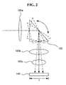
FIG. 2 , it can be understood that an angle of the incident surface of the first opticalpath changing unit 120 is adjusted in the vertical direction, and the width (t) of theimage generating unit 140 corresponds to the thickness of the image photographing device. In other words, the thickness of image photographing devices in most ordinary cameras extends in a direction horizontal to an optical axis incident onto the objective 120a, and light incident through the objective 120a turns to the vertical direction by the first opticalpath changing unit 120 and reaches theimage generating unit 140 in this embodiment of the present invention, by reason of which it can be understood that the width (t) of theimage generating unit 140 corresponds to the thickness of the image photographing device. - Accordingly, when an optical path of light incident to the image photographing device is changed as illustrated in
FIG. 2 , an anti-shake function can be implemented through the first opticalpath changing unit 120 without increasing the thickness of the image photographing device. - With respect to this, the
angle adjusting unit 130 can determine in which direction an angle of the incident surface of the first opticalpath changing unit 120 is changed, based on a sensing result from theshake sensing unit 110, and can change the optical path of the incident light by adjusting an angle of the incident surface according to a result of the determination. - Changing the optical path of the incident light in this way is aimed at correcting a shake occurring while the incident light, the optical path of which has been changed by the first optical
path changing unit 120, passes through avariator 120b and acompensator 120c, and reaches theimage generating unit 140 provided with an image sensor. Further, an optical path, to which the optical path of the incident light is changed by the first opticalpath changing unit 120, may vary according to the size of the image sensor. Further, the positions of therespective lenses FIG. 2 , are merely an example for promoting the understanding of the present invention, and may vary according to the type and specification of the image photographing device. - In this embodiment of the present invention, a VCM (Voice Coil Module), a stepping motor, a DC/AC motor, an ultrasonic motor, an organic/plastic driver and so forth may be used as the
angle adjusting unit 130, but the present invention is not limited thereto. - In addition, although
FIG. 2 illustrates that the first opticalpath changing unit 120 adjusts an angle of its incident surface in the vertical direction, this is merely an example for promoting the understanding of the present invention, and any type of modification may be made to the direction in which an angle of the incident surface is adjusted. -
FIG. 3 is a schematic view illustrating an apparatus for correcting a shake of an image photographing device according to a second preferred embodiment of the present invention. Here, the second embodiment ofFIG. 3 can be understood as an embodiment where, in the above-mentioned shake correction apparatus ofFIGS. 1 and2 , a shake of the image photographing device is corrected in such a manner that the first opticalpath changing unit 120 changes an optical path in the first direction, and a position of an image sensor included in theimage generating unit 140 is changed in the second direction. - As illustrated in the drawing, in this embodiment of the present invention, the first optical
path changing unit 120 may be formed of a prism, a mirror and the like, so that it can change an optical path of light incident through an objective 120a. Here, an optical path, to which the optical path of the incident light is changed, can be determined according to an angle of the incident surface, and an angle of the incident surface can be adjusted by theangle adjusting unit 130. - In other words, the
angle adjusting unit 130 can adjust an angle of the incident surface, based on the shake sensed by theshake sensing unit 110, and an optical path, to which the optical path of the incident light is changed, can be determined according to the adjusted angle. - The
image generating unit 140 may include animage sensor 141 receiving light and adriver 142 changing a position of theimage sensor 141. - While the first optical
path changing unit 120 corrects a shake by changing an optical path in the first direction, thedriver 142 can correct the shake by changing a position of theimage sensor 141 in the second direction. In other words, when a shake occurs in the image photographing device, a shake component in the first direction, that is, the vertical direction, can be corrected according to an angle of the incident surface of the first opticalpath changing unit 120, and a shake component in the second direction, that is, the horizontal direction, can be corrected according to a position of theimage sensor 141, which is changed by thedriver 142. Of course, the directions in which an angle of the incident surface of the first opticalpath changing unit 120 and a position of theimage sensor 141 in theimage generating unit 140 may be reversed to each other. -
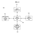
FIG. 4 is a block diagram illustrating an apparatus for correcting a shake of an image photographing device according to a third preferred embodiment of the present invention, andFIG. 5 is a schematic view illustrating the same. - As illustrated in the drawings, the
apparatus 100 for correcting a shake of an image photographing device according to the third embodiment of the present invention includes ashake sensing unit 110 sensing a shake of the image photographing device which photographs an image of a given subject, a first opticalpath changing unit 120 changing an optical path of light incident to the image photographing device, a second opticalpath changing unit 150 changing an optical path, to which the optical path of the incident light has been changed by the first opticalpath changing unit 120, once again, and aimage generating unit 140 generating the image of the subject through light, the optical path of which has been changed again by the second opticalpath changing unit 150. - Here, the
shake sensing unit 110 may include a gyro sensor, an acceleration sensor, a terrestrial magnetism sensor, an image analysis algorithm and so forth which are provided in the image photographing device to sense a shake of a user who uses the image photographing device, but the present invention is not limited thereto. - The first optical
path changing unit 120 changes an optical path of light, which is incident through the objective 120a, in a direction perpendicular to an optical axis incident onto the objective 120a, and the second opticalpath changing unit 150 changes on optical path, to which the optical path of the incident light has been changed by the first opticalpath changing unit 120, once again in a direction horizontal to the optical axis incident onto the objective 120a. Thus, a light receiving area, at which light arrives in theimage generating unit 140, is positioned in a direction perpendicular to the optical axis incident onto the objective 120a. In this case, that is, when theimage generating unit 140 is positioned in a direction perpendicular to the ground in this way, a limitation on increasing the width of theimage generating unit 140 is relieved. In contrast with this, when the light receiving area, at which light arrives in theimage generating unit 140, is positioned in a direction horizontal to the optical axis incident onto the objective 120a, as described inFIG. 2 , there is a significant limitation on increasing the width of theimage generating unit 140 because the thickness of the image photographing device, corresponding to the width of theimage generating unit 140, increases. Thus, in this embodiment of the present invention, an increase in the thickness of the image photographing device can be prevented even when a driver to be described below is provided in order to change a position of an image sensor included in theimage generating unit 140. - In addition, the
apparatus 100 for correcting a shake of an image photographing device may include anangle adjusting unit 130 capable of adjusting an angle of an incident surface in the first and second opticalpath changing units angle adjusting unit 130 can adjust an angle of the incident surface of the first opticalpath changing unit 120 in the first direction, and adjust an angle of the incident surface of the second opticalpath changing unit 150 in the second direction, according to a sensing result from theshake sensing unit 110. Of course, although this embodiment of the present invention is described by exemplifying a case where the first and second opticalpath changing units path changing units - As mentioned above, in this embodiment of the present invention, a position of the image sensor, which receives light in the
image generating unit 140, may be adjusted in order to correct a shake, in addition to adjusting angles of the incident surfaces of the first and second opticalpath changing units image generating unit 140 may include theimage sensor 141 and adriver 142 changing a position of theimage sensor 141. Thedriver 142 can correct a shake by changing a position of theimage sensor 141 according to a sensing result from theshake sensing unit 110. Here, since theimage generating unit 140 is disposed in a direction perpendicular to the optical axis incident onto the objective 120a, an increase in the thickness of the image photographing device can be prevented even when thedriver 142 changing a position of theimage sensor 141 is provided. -
FIG. 7 is a flowchart illustrating a method of correcting a shake of an image photographing device according to the first embodiment of the present invention. Here, this method ofFIG. 7 can be understood as a method of operating the apparatus described inFIGS. 1 and2 . - As illustrated in the drawing, the method of correcting a shake of an image photographing device according to the first embodiment of the present invention begins with sensing a shake, occurring in the image photographing device, by the shake sensing unit 110 (S110). Here, as described above, the
shake sensing unit 110 includes a gyro sensor, an acceleration sensor, a terrestrial magnetism sensor, an image analysis algorithm and so forth, so that it can sense shake occurrence. According to the shake sensed in theshake sensing unit 110, theangle adjusting unit 130 determines in which direction an angle of the incident surface of the first opticalpath changing unit 120 is adjusted (S120), and adjusts an angle of the incident surface of the first opticalpath changing unit 120 in the determined direction (S130). InFIG. 7 , the first opticalpath changing unit 120 may adjust an angle of its incident surface in at least one of the first and second directions. For example, if the first direction corresponds to a direction perpendicular to an optical axis incident onto the objective 120a, and the second direction corresponds to a direction horizontal to the optical axis incident onto the objective 120a, as assumed above, the first opticalpath changing unit 120 can correct the shake occurring in the image photographing device by adjusting an angle of its incident surface in at least one of the vertical and horizontal directions. - The
image generating unit 140 receives light, the optical path of which has been changed by the first opticalpath changing unit 120, to thereby generate an image of a subject (S140). -
FIG. 8 is a flowchart illustrating a method of correcting a shake of an image photographing device according to the second embodiment of the present invention. Here, this method ofFIG. 8 can be understood as a method of operating the apparatus described inFIG. 3 . - As illustrated in the drawing, the method of correcting a shake of an image photographing device according to the second embodiment of the present invention begins with sensing a shake, occurring in the image photographing device, by the shake sensing unit 110 (S210). Here, as described above, the
shake sensing unit 110 includes a gyro sensor, an acceleration sensor, a terrestrial magnetism sensor, an image analysis algorithm and so forth, so that it can sense shake occurrence. InFIG. 8 , by way of example, a description will be given of a case where theshake sensing unit 110 senses both a shake component in the first direction and a shake component in the second direction. Of course, as mentioned above, the first direction corresponds to a direction perpendicular to an optical axis incident onto the objective 120a, and the second direction corresponds to a direction horizontal to the optical axis incident onto the objective 120a. InFIG. 8 , by way of example, a description will also be given of a case where the first opticalpath changing unit 120 corrects the shake component in the first direction, and theimage generating unit 140 corrects the shake component in the second direction. - The
angle adjusting unit 130 adjusts an angle of the incident surface of the first opticalpath changing unit 120 in the first direction according to the shake component in the first direction among the shake sensed in the shake sensing unit 110 (S220). - The
driver 142 adjusts a position of theimage sensor 141 in the second direction according to the shake component in the second direction among the shake sensed in the shake sensing unit 110 (S230). - Thus, if the shake components in the first and second directions are corrected by adjusting an angle of the incident surface of the first optical
path changing unit 120 and a position of theimage sensor 141, theimage generating unit 140 generates an image of a subject through light reaching the image sensor 141 (S240). -
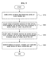
FIG. 9 is a flowchart illustrating a method of correcting a shake of an image photographing device according to the third embodiment of the present invention. Here, this method ofFIG. 8 can be understood as a method of operating the apparatus described inFIGS. 4 to 6 . - As illustrated in the drawing, the method of correcting a shake of an image photographing device according to the third embodiment of the present invention begins with sensing a shake, occurring in the image photographing device, by the shake sensing unit 110 (S310). Here, as described above, the
shake sensing unit 110 includes a gyro sensor, an acceleration sensor, a terrestrial magnetism sensor, an image analysis algorithm and so forth, so that it can sense shake occurrence. - The
angle adjusting unit 130 corrects the sensed shake by adjusting an angle of the incident surface of the first opticalpath changing unit 120 in the first direction (S320) and adjusting an angle of the incident surface of the second opticalpath changing unit 150 in the second direction (S330). InFIG. 9 , by way of example, a description is given of a case where theangle adjusting unit 130 adjusts an angle of the incident surface of the first opticalpath changing unit 120 in the first direction and adjusts an angle of the incident surface of the second opticalpath changing unit 150 in the second direction, but the present invention is not limited thereto. For example, theangle adjusting unit 130 may correct the sensed shake by setting one of the incident surfaces of the first and second opticalpath changing units - The
image generating unit 140 generates an image of a subject through light reaching the image sensor 141 (S340). - In
FIG. 9 , the light receiving area, at which light arrives in theimage generating unit 140, is positioned in a direction perpendicular to the optical axis incident onto the objective 120a in order that light, the optical path of which is changed twice by the first and second opticalpath changing units image sensor 141. When theimage generating unit 140 is positioned perpendicular to the optical axis in this way, the thickness of the image photographing device does not increase even when the width of theimage generating unit 140 increases. Thus, the shake occurring in the image photographing device may be corrected by providing theimage generating unit 140 with thedriver 142 to change a position of theimage sensor 141. In other words, inFIG. 9 , it is also possible to fix one of the first and second opticalpath changing units image sensor 141 in the second direction, thereby correcting the shake occurring in the image photographing device. - Accordingly, it is possible not only to correct the shake components in the first and second directions by means of the first and second optical
path changing units path changing units image sensor 141. - The terms "- unit", as used herein, means a software component or a hardware component such as a FPGA (Field Programmable Gate Array) or an ASIC (Application Specific Integrated Circuit), which performs certain tasks, but is not limited to software or hardware. A module may be configured in such a manner as to reside on an addressable storage medium or may be configured in such a manner as to execute one or more processors. Thus, a module may include, by way of example, components such as software components, object-oriented software components, class components and task components, processes, functions, attributes, procedures, subroutines, segments of program codes, drivers, firmware, microcode, circuitry, data, databases, data architectures, tables, arrays, and variables. The functionality provided by the components and modules may be incorporated into fewer components and modules or may be further separated into additional components and modules.
- According to the inventive apparatus and method for correcting a shake of an image photographing device, as described above, an optical path of light incident to the image photographing device is appropriately changed through a prism, a mirror and the like, so that an increase in the thickness of the image photographing device can be prevented, and simultaneously an anti-shake function can be implemented.
- Although preferred embodiments of the present invention have been described for illustrative purposes, those skilled in the art will appreciate that various modifications, additions and substitutions are possible, without departing from the essential features and the scope and spirit of the invention as disclosed in the accompanying claims. Therefore, it should be appreciated that the embodiments described above are not limitative, but only illustrative.
Claims (25)
- An apparatus for correcting a shake of an image photographing device, the apparatus comprising:a shake sensing unit sensing the shake of the image photographing device which photographs an image of a subject;a first optical path changing unit changing an optical path of light incident to the image photographing device;an angle adjusting unit adjusting an angle of an light-incident surface of the first optical path changing unit according to the sensed shake; andan image generating unit generating the image of the subject through the light, the optical path of which has been changed by the first optical path changing unit.
- The apparatus of claim 1, wherein the first optical path changing unit comprises at least one of a prism and a mirror.
- The apparatus of claim 1, wherein the angle adjusting unit comprises at least one of a VCM (Voice Coil Motor), a stepping motor, a DC/AC motor, an ultrasonic motor and an organic/plastic driver for changing the angle of the light-incident surface of the first optical path changing unit.
- The apparatus of claim 1, wherein the angle adjusting unit adjusts the angle of the light-incident surface of the first optical path changing unit in at least one of a one-dimensional manner and a two-dimensional manner.
- The apparatus of claim 1, wherein an optical path, to which the optical path of the light incident to the image photographing device is changed by the first optical path changing unit, is determined according to a light receiving area of the image generating unit.
- An apparatus for correcting a shake of an image photographing device, the apparatus comprising:a shake sensing unit sensing the shake of the image photographing device which photographs an image of a subject;a first optical path changing unit changing an optical path of light incident to the image photographing device;an angle adjusting unit adjusting an angle of a light-incident surface of the first optical path changing unit in a first direction according to the sensed shake; andan image generating unit generating the image of the subject by changing a position of an area receiving the light, the optical path of which has been changed by the first optical path changing unit, in a second direction.
- The apparatus of claim 6, wherein the image generating unit comprises:an image sensor having the area receiving the light; anda driver changing a position of the image sensor in the second direction according to the sensed shake.
- An apparatus for correcting a shake of an image photographing device, the apparatus comprising:a shake sensing unit sensing the shake of the image photographing device which photographs an image of a subject;a first optical path changing unit changing an optical path of light incident to the image photographing device;a second optical path changing unit changing an optical path, to which the optical path of the light has been changed by the first optical path changing unit, once again; andan image generating unit generating the image of the subject through the light, the optical path of which has been changed again by the second optical path changing unit.
- The apparatus of claim 8, wherein the first optical path changing unit comprises at least one of a prism and a mirror.
- The apparatus of claim 8, further comprising an angle adjusting unit adjusting an angle of at least one of light-incident surfaces of the first and second optical path changing units.
- The apparatus of claim 10, wherein the angle adjusting unit adjusts angles of the light-incident surfaces of the first and second optical path changing units in different directions.
- The apparatus of claim 10, wherein an optical path, to which the optical path of the light is changed by the second optical path changing unit, is determined according to a light receiving area of the image generating unit.
- The apparatus of claim 8, wherein the image generating unit comprises:an image sensor having the light receiving area; anda driver changing a position of the image sensor according to the sensed shake.
- The apparatus of claim 13, wherein the angle adjusting unit adjusts the angle of at least one of the light-incident surfaces of the first and second optical path changing units in a first direction, and the driver changes the position of the image sensor in a second direction.
- A method of correcting a shake of an image photographing device, the method comprising:sensing the shake of the image photographing device which photographs an image of a subject;changing an optical path of light incident to the image photographing device;when the optical path of the light is changed, adjusting an angle of an optical path, to which the optical path of the light is changed, according to the sensed shake; andgenerating the image of the subject through the light, the optical path of which has been changed.
- The method of claim 15, wherein the changing the optical path of the light comprises changing the optical path of the light by using at least one of a prism and a mirror.
- The method of claim 15, wherein the adjusting the angle of the optical path comprises adjusting the angle of the optical path by using at least one of a VCM (Voice Coil Motor), a stepping motor, a DC/AC motor, an ultrasonic motor and an organic/plastic driver for changing an angle of the light-incident surface.
- The method of claim 15, wherein the adjusting the angle of the optical path comprises adjusting the angle of the light-incident surface in at least one of a one-dimensional direction and a two-dimensional direction.
- The method of claim 15, wherein the optical path, to which the optical path of the light incident to the image photographing device is changed, is determined according to an area at which the light arrives for generating the image of the subject.
- A method of correcting a shake of an image photographing device, the method comprising:sensing the shake of the image photographing device which photographs an image of a subject;changing an optical path of light incident to the image photographing device;changing the changed optical path of the light once again; andgenerating the image of the subject through the light, the optical path of which has been changed again.
- The method of claim 20, wherein each of the changing the optical path of the light and the changing the optical path of the light once again comprises changing the optical path of the light by using at least one of a prism and a mirror.
- The method of claim 21, wherein each of the changing the optical path of the light and the changing the optical path of the light once again comprises adjusting an angle of a light-incident surface of at least one of the prism and the mirror.
- The method of claim 22, wherein the adjusting the angle of the light-incident surface comprises adjusting the angle of the light-incident surface in a first direction when the optical path of the light is changed or changed again.
- The method of claim 23, wherein the adjusting the angle of the light-incident surface comprises:adjusting the angle of the light-incident surface in the first direction when the optical path of the light is changed; andadjusting the angle of the light-incident surface in a second direction when the optical path of the light is changed again.
- The method of claim 20, wherein the generating the image of the subject comprises changing a position of an image sensor, which has a light receiving area, according to the sensed shake.
Applications Claiming Priority (1)
| Application Number | Priority Date | Filing Date | Title |
|---|---|---|---|
| KR1020060121741A KR100871566B1 (en) | 2006-12-04 | 2006-12-04 | Apparatus and method for preventing shaking of image photographing device |
Publications (1)
| Publication Number | Publication Date |
|---|---|
| EP1931135A1 true EP1931135A1 (en) | 2008-06-11 |
Family
ID=39156164
Family Applications (1)
| Application Number | Title | Priority Date | Filing Date |
|---|---|---|---|
| EP07122227A Ceased EP1931135A1 (en) | 2006-12-04 | 2007-12-04 | Apparatus and method for correcting shake of image photographing device |
Country Status (5)
| Country | Link |
|---|---|
| US (1) | US20080129831A1 (en) |
| EP (1) | EP1931135A1 (en) |
| JP (2) | JP2008139893A (en) |
| KR (1) | KR100871566B1 (en) |
| CN (1) | CN101201462A (en) |
Cited By (9)
| Publication number | Priority date | Publication date | Assignee | Title |
|---|---|---|---|---|
| GB2516743A (en) * | 2013-05-28 | 2015-02-04 | Canon Kk | Optical device, control method therefor, and storage medium storing control program therefor |
| WO2018189321A1 (en) * | 2017-04-13 | 2018-10-18 | Fraunhofer-Gesellschaft zur Förderung der angewandten Forschung e.V. | Multi-aperture imaging device, imaging system and method for providing a multi-aperture imaging device |
| EP3696587A1 (en) * | 2015-04-16 | 2020-08-19 | Corephotonics Ltd. | Auto focus and optical image stabilization in a compact folded camera |
| EP3722860A1 (en) * | 2015-05-28 | 2020-10-14 | Corephotonics Ltd. | Bi-directional stiffness for optical image stabilization and auto-focus in a digital camera |
| EP3707893A4 (en) * | 2018-02-12 | 2020-12-23 | Corephotonics Ltd. | Folded camera with optical image stabilization |
| US11070731B2 (en) | 2017-03-10 | 2021-07-20 | Fraunhofer-Gesellschaft zur Förderung der angewandten Forschung e.V. | Multi-aperture imaging device, imaging system and method for making available a multi-aperture imaging device |
| EP3816694A3 (en) * | 2019-10-09 | 2021-07-21 | Tdk Taiwan Corp. | Optical system |
| US11457152B2 (en) | 2017-04-13 | 2022-09-27 | Fraunhofer-Gesellschaft zur Förderung der angewandten Forschung e.V. | Device for imaging partial fields of view, multi-aperture imaging device and method of providing same |
| EP4246993A3 (en) * | 2016-12-28 | 2024-03-06 | Corephotonics Ltd. | Folded camera structure with an extended light-folding-element scanning range |
Families Citing this family (63)
| Publication number | Priority date | Publication date | Assignee | Title |
|---|---|---|---|---|
| KR100956226B1 (en) * | 2008-09-05 | 2010-05-04 | 삼성전기주식회사 | Camera module comprising gyro sensor |
| JP5751787B2 (en) * | 2010-09-28 | 2015-07-22 | スタンレー電気株式会社 | Light deflection liquid crystal element, projection display, and shake correction imaging apparatus |
| US8988564B2 (en) * | 2011-09-09 | 2015-03-24 | Apple Inc. | Digital camera with light splitter |
| JP6004785B2 (en) * | 2012-06-29 | 2016-10-12 | キヤノン株式会社 | Imaging apparatus, optical apparatus, imaging system, and control method |
| CN103676455B (en) | 2012-09-26 | 2016-06-29 | 爱佩仪光电技术(深圳)有限公司 | The automatic adjustment method of optics shockproof camera module and system |
| CN113259565B (en) | 2012-11-28 | 2023-05-19 | 核心光电有限公司 | Multi-aperture imaging system |
| US8861946B2 (en) | 2013-03-07 | 2014-10-14 | Jahwa Electronics Co., Ltd. | Device for driving camera lens module in portable terminal |
| US9185291B1 (en) | 2013-06-13 | 2015-11-10 | Corephotonics Ltd. | Dual aperture zoom digital camera |
| KR101757101B1 (en) | 2013-07-04 | 2017-07-12 | 코어포토닉스 리미티드 | Miniature telephoto lens assembly |
| EP3028443A2 (en) | 2013-08-01 | 2016-06-08 | Corephotonics Ltd. | Thin multi-aperture imaging system with auto-focus and methods for using same |
| JP2015102775A (en) * | 2013-11-27 | 2015-06-04 | キヤノン株式会社 | Image tremor correction device and control method of the same |
| CN103676405A (en) * | 2013-12-02 | 2014-03-26 | 宇龙计算机通信科技(深圳)有限公司 | Optical imaging device, optical system and mobile terminal |
| US9338357B2 (en) * | 2014-01-30 | 2016-05-10 | Hoya Corporation | Imaging apparatus |
| KR102163045B1 (en) * | 2014-02-17 | 2020-10-08 | 삼성전기주식회사 | Apparatus and method for correcting image |
| US9392188B2 (en) | 2014-08-10 | 2016-07-12 | Corephotonics Ltd. | Zoom dual-aperture camera with folded lens |
| JP6600163B2 (en) * | 2014-08-19 | 2019-10-30 | キヤノン株式会社 | Image blur correction apparatus and control method thereof |
| CN107209404B (en) | 2015-01-03 | 2021-01-15 | 核心光电有限公司 | Miniature telephoto lens module and camera using the same |
| KR102263924B1 (en) | 2015-08-13 | 2021-06-11 | 코어포토닉스 리미티드 | Dual aperture zoom camera with video support and switching/non-switching dynamic control |
| KR102225727B1 (en) * | 2015-09-06 | 2021-03-10 | 코어포토닉스 리미티드 | Auto focus and optical image stabilization with roll compensation in a compact folded camera |
| KR101928716B1 (en) | 2015-12-29 | 2018-12-12 | 코어포토닉스 리미티드 | Dual-aperture zoom digital camera with auto-adjustable tele-view (FOV) |
| CN116661090A (en) * | 2016-05-10 | 2023-08-29 | 台湾东电化股份有限公司 | Lens system |
| EP3758356B1 (en) | 2016-05-30 | 2021-10-20 | Corephotonics Ltd. | Actuator |
| CN107515459A (en) * | 2016-06-17 | 2017-12-26 | 宁波舜宇光电信息有限公司 | Periscopic camera module and its imaging method |
| EP4270978A3 (en) | 2016-06-19 | 2024-02-14 | Corephotonics Ltd. | Frame synchronization in a dual-aperture camera system |
| KR102390572B1 (en) | 2016-07-07 | 2022-04-25 | 코어포토닉스 리미티드 | Linear ball guided voice coil motor for folded optic |
| US10248191B2 (en) * | 2016-12-12 | 2019-04-02 | Microsoft Technology Licensing, Llc | Virtual rigid framework for sensor subsystem |
| KR102365926B1 (en) | 2017-01-12 | 2022-02-23 | 코어포토닉스 리미티드 | Compact folded camera |
| CN110582724B (en) | 2017-03-15 | 2022-01-04 | 核心光电有限公司 | Camera device with panoramic scanning range |
| WO2019048904A1 (en) | 2017-09-06 | 2019-03-14 | Corephotonics Ltd. | Combined stereoscopic and phase detection depth mapping in a dual aperture camera |
| US10951834B2 (en) | 2017-10-03 | 2021-03-16 | Corephotonics Ltd. | Synthetically enlarged camera aperture |
| CN110140076B (en) | 2017-11-23 | 2021-05-21 | 核心光电有限公司 | Compact folding camera structure |
| EP3552050B1 (en) | 2018-02-05 | 2021-06-02 | Corephotonics Ltd. | Reduced height penalty for folded camera |
| US10694168B2 (en) | 2018-04-22 | 2020-06-23 | Corephotonics Ltd. | System and method for mitigating or preventing eye damage from structured light IR/NIR projector systems |
| KR102299752B1 (en) | 2018-04-23 | 2021-09-08 | 코어포토닉스 리미티드 | Optical path folding element with extended two-degree-of-freedom rotation range |
| JP7068581B2 (en) * | 2018-07-04 | 2022-05-17 | ミツミ電機株式会社 | Camera actuators, camera modules, and camera-mounted devices |
| JP7028983B2 (en) | 2018-08-04 | 2022-03-02 | コアフォトニクス リミテッド | Switchable continuous display information system on the camera |
| WO2020039302A1 (en) | 2018-08-22 | 2020-02-27 | Corephotonics Ltd. | Two-state zoom folded camera |
| CN111355872B (en) * | 2018-12-24 | 2021-09-07 | 华为技术有限公司 | Camera module, anti-shake subassembly and terminal |
| WO2020144528A1 (en) | 2019-01-07 | 2020-07-16 | Corephotonics Ltd. | Rotation mechanism with sliding joint |
| CN109633854B (en) * | 2019-01-08 | 2020-09-29 | 瑞声通讯科技(常州)有限公司 | Image collector and mobile electronic equipment |
| KR102268094B1 (en) | 2019-03-09 | 2021-06-22 | 코어포토닉스 리미티드 | System and method for dynamic stereoscopic calibration |
| CN110460776B (en) * | 2019-03-19 | 2022-08-02 | 诚瑞光学(常州)股份有限公司 | Camera device with hand shake correction function |
| WO2021019318A1 (en) | 2019-07-31 | 2021-02-04 | Corephotonics Ltd. | System and method for creating background blur in camera panning or motion |
| CN112394536B (en) * | 2019-07-31 | 2022-04-29 | 华为技术有限公司 | Optical anti-shake device and control method |
| JP7381241B2 (en) * | 2019-08-01 | 2023-11-15 | ニデックインスツルメンツ株式会社 | optical unit |
| US11659135B2 (en) | 2019-10-30 | 2023-05-23 | Corephotonics Ltd. | Slow or fast motion video using depth information |
| US11949976B2 (en) | 2019-12-09 | 2024-04-02 | Corephotonics Ltd. | Systems and methods for obtaining a smart panoramic image |
| EP4049444A4 (en) | 2019-12-09 | 2022-11-16 | Corephotonics Ltd. | Systems and methods for obtaining a smart panoramic image |
| JP6864761B2 (en) * | 2020-02-27 | 2021-04-28 | ジョウシュウシ レイテック オプトロニクス カンパニーリミテッド | Imaging device with image stabilization function |
| WO2021168784A1 (en) * | 2020-02-28 | 2021-09-02 | 南昌欧菲光电技术有限公司 | Anti-shake component, camera module, and electronic device |
| KR20220003550A (en) | 2020-04-26 | 2022-01-10 | 코어포토닉스 리미티드 | Temperature Control for Hall Bar Sensor Calibration |
| CN111541833A (en) * | 2020-04-29 | 2020-08-14 | 维沃移动通信有限公司 | Camera module, electronic equipment and camera shooting method |
| WO2021226792A1 (en) * | 2020-05-11 | 2021-11-18 | 南昌欧菲光电技术有限公司 | Lens, camera module, and electronic device |
| CN117372249A (en) | 2020-05-17 | 2024-01-09 | 核心光电有限公司 | Image stitching of full field of view reference images |
| WO2021245488A1 (en) | 2020-05-30 | 2021-12-09 | Corephotonics Ltd. | Systems and methods for obtaining a super macro image |
| CN111896965B (en) * | 2020-06-09 | 2023-05-09 | 深圳职业技术学院 | Laser ranging calibration method and laser range finder capable of being calibrated automatically |
| EP4045960A4 (en) | 2020-07-15 | 2022-12-14 | Corephotonics Ltd. | Point of view aberrations correction in a scanning folded camera |
| US11637977B2 (en) | 2020-07-15 | 2023-04-25 | Corephotonics Ltd. | Image sensors and sensing methods to obtain time-of-flight and phase detection information |
| WO2022023914A1 (en) | 2020-07-31 | 2022-02-03 | Corephotonics Ltd. | Hall sensor - magnet geometry for large stroke linear position sensing |
| CN112014935A (en) * | 2020-09-04 | 2020-12-01 | 广东省科学院半导体研究所 | Visual anti-shake device and method |
| KR20220094781A (en) * | 2020-12-29 | 2022-07-06 | 엘지이노텍 주식회사 | Camera module |
| WO2023018142A1 (en) * | 2021-08-09 | 2023-02-16 | 엘지이노텍 주식회사 | Camera module |
| CN117768752A (en) * | 2022-09-26 | 2024-03-26 | 华为技术有限公司 | Periscope type camera module, optical anti-shake method and related equipment |
Citations (11)
| Publication number | Priority date | Publication date | Assignee | Title |
|---|---|---|---|---|
| US3468595A (en) * | 1966-08-29 | 1969-09-23 | Optical Res & Dev Corp | Optical stabilization by reflecting means |
| US5041852A (en) * | 1990-10-18 | 1991-08-20 | Fjui Photo Film Co., Ltd. | Camera shake correction system |
| US5333076A (en) | 1988-01-21 | 1994-07-26 | Fairchild Weston Systems, Inc. | Stabilized imaging system |
| US5946032A (en) * | 1992-01-31 | 1999-08-31 | Sony Corporation | Camera shake correcting apparatus having damping coils for yaw and pitch |
| US6243132B1 (en) * | 1996-10-30 | 2001-06-05 | Samsung Electronics Co., Ltd. | Jitter control apparatus for video camera |
| US20030067544A1 (en) * | 2001-10-01 | 2003-04-10 | Shigeru Wada | Image taking device having image-blur compensator |
| US20050057659A1 (en) | 2003-09-16 | 2005-03-17 | Takami Hasegawa | Camera image shake correcting device |
| US20050206737A1 (en) * | 2004-03-22 | 2005-09-22 | Gim Dong W | Imaging stabilizer using micromirror array lens |
| JP2005352240A (en) | 2004-06-11 | 2005-12-22 | Olympus Corp | Optical system |
| US20060127073A1 (en) | 2004-12-09 | 2006-06-15 | Konica Minolta Photo Imaging, Inc. | Camera shake compensation mechanism and optical apparatus using the camera shake compensation mechanism |
| US20060177208A1 (en) * | 2005-02-07 | 2006-08-10 | Fuji Photo Film Co., Ltd. | Imaging apparatus |
Family Cites Families (11)
| Publication number | Priority date | Publication date | Assignee | Title |
|---|---|---|---|---|
| DE69715198T3 (en) * | 1996-06-18 | 2009-07-09 | Corp. Sony | OPTICAL IMAGE RECORDING SYSTEM AND RELATED DEVELOPMENT DEVICE |
| JPH11305276A (en) * | 1998-04-20 | 1999-11-05 | Asahi Optical Co Ltd | Image blurring correction camera and image blurring correcting method for camera |
| JPH11305281A (en) * | 1998-04-20 | 1999-11-05 | Asahi Optical Co Ltd | Image blurring correction camera and image blurring correcting method for camera |
| JP3929778B2 (en) * | 2002-01-16 | 2007-06-13 | 株式会社リコー | Imaging device |
| JP3861815B2 (en) * | 2003-01-17 | 2006-12-27 | コニカミノルタフォトイメージング株式会社 | Camera with image stabilization function |
| JP2004301939A (en) * | 2003-03-28 | 2004-10-28 | Sony Corp | Camera system, camera, and interchangeable lens |
| JP4225948B2 (en) | 2004-06-16 | 2009-02-18 | シャープ株式会社 | Imaging device |
| JP2006058840A (en) * | 2004-07-23 | 2006-03-02 | Konica Minolta Opto Inc | Imaging optical system, imaging lens device and digital equipment |
| KR20060071224A (en) * | 2004-12-21 | 2006-06-26 | 삼성전자주식회사 | Image stabilizer of camera |
| JP2006197198A (en) * | 2005-01-13 | 2006-07-27 | Sharp Corp | Image pickup device with camera shake correcting function and portable electronic equipment |
| JP4720444B2 (en) | 2005-11-10 | 2011-07-13 | セイコーエプソン株式会社 | Optical correction device, glasses-type display device |
-
2006
- 2006-12-04 KR KR1020060121741A patent/KR100871566B1/en active IP Right Grant
-
2007
- 2007-11-16 US US11/984,420 patent/US20080129831A1/en not_active Abandoned
- 2007-12-03 CN CNA2007101947634A patent/CN101201462A/en active Pending
- 2007-12-04 JP JP2007313492A patent/JP2008139893A/en active Pending
- 2007-12-04 EP EP07122227A patent/EP1931135A1/en not_active Ceased
-
2014
- 2014-02-21 JP JP2014032195A patent/JP5836408B2/en not_active Expired - Fee Related
Patent Citations (11)
| Publication number | Priority date | Publication date | Assignee | Title |
|---|---|---|---|---|
| US3468595A (en) * | 1966-08-29 | 1969-09-23 | Optical Res & Dev Corp | Optical stabilization by reflecting means |
| US5333076A (en) | 1988-01-21 | 1994-07-26 | Fairchild Weston Systems, Inc. | Stabilized imaging system |
| US5041852A (en) * | 1990-10-18 | 1991-08-20 | Fjui Photo Film Co., Ltd. | Camera shake correction system |
| US5946032A (en) * | 1992-01-31 | 1999-08-31 | Sony Corporation | Camera shake correcting apparatus having damping coils for yaw and pitch |
| US6243132B1 (en) * | 1996-10-30 | 2001-06-05 | Samsung Electronics Co., Ltd. | Jitter control apparatus for video camera |
| US20030067544A1 (en) * | 2001-10-01 | 2003-04-10 | Shigeru Wada | Image taking device having image-blur compensator |
| US20050057659A1 (en) | 2003-09-16 | 2005-03-17 | Takami Hasegawa | Camera image shake correcting device |
| US20050206737A1 (en) * | 2004-03-22 | 2005-09-22 | Gim Dong W | Imaging stabilizer using micromirror array lens |
| JP2005352240A (en) | 2004-06-11 | 2005-12-22 | Olympus Corp | Optical system |
| US20060127073A1 (en) | 2004-12-09 | 2006-06-15 | Konica Minolta Photo Imaging, Inc. | Camera shake compensation mechanism and optical apparatus using the camera shake compensation mechanism |
| US20060177208A1 (en) * | 2005-02-07 | 2006-08-10 | Fuji Photo Film Co., Ltd. | Imaging apparatus |
Cited By (19)
| Publication number | Priority date | Publication date | Assignee | Title |
|---|---|---|---|---|
| US9247138B2 (en) | 2013-05-28 | 2016-01-26 | Canon Kabushiki Kaisha | Optical device, control method therefor, and storage medium storing control program therefor |
| GB2516743B (en) * | 2013-05-28 | 2016-09-21 | Canon Kk | Optical device, control method for the optical device, and stroage medium storing a control program for the optical device |
| US9621807B2 (en) | 2013-05-28 | 2017-04-11 | Canon Kabushiki Kaisha | Optical device, control method therefor, and storage medium storing control program therefor |
| GB2516743A (en) * | 2013-05-28 | 2015-02-04 | Canon Kk | Optical device, control method therefor, and storage medium storing control program therefor |
| EP3696587A1 (en) * | 2015-04-16 | 2020-08-19 | Corephotonics Ltd. | Auto focus and optical image stabilization in a compact folded camera |
| EP4220267A3 (en) * | 2015-04-16 | 2023-08-09 | Corephotonics Ltd. | Auto focus and optical image stabilization in a compact folded camera |
| EP3722860A1 (en) * | 2015-05-28 | 2020-10-14 | Corephotonics Ltd. | Bi-directional stiffness for optical image stabilization and auto-focus in a digital camera |
| EP4246993A3 (en) * | 2016-12-28 | 2024-03-06 | Corephotonics Ltd. | Folded camera structure with an extended light-folding-element scanning range |
| US11070731B2 (en) | 2017-03-10 | 2021-07-20 | Fraunhofer-Gesellschaft zur Förderung der angewandten Forschung e.V. | Multi-aperture imaging device, imaging system and method for making available a multi-aperture imaging device |
| US10996460B2 (en) | 2017-04-13 | 2021-05-04 | Fraunhofer-Gesellschaft zur Förderung der angewandten Forschung e.V. | Multi-aperture imaging device, imaging system and method of providing a multi-aperture imaging device |
| US11457152B2 (en) | 2017-04-13 | 2022-09-27 | Fraunhofer-Gesellschaft zur Förderung der angewandten Forschung e.V. | Device for imaging partial fields of view, multi-aperture imaging device and method of providing same |
| EP3860108B1 (en) * | 2017-04-13 | 2023-06-21 | Fraunhofer-Gesellschaft zur Förderung der angewandten Forschung e.V. | Multi-aperture imaging device, imaging system and method for providing a multi-aperture imaging device |
| WO2018189321A1 (en) * | 2017-04-13 | 2018-10-18 | Fraunhofer-Gesellschaft zur Förderung der angewandten Forschung e.V. | Multi-aperture imaging device, imaging system and method for providing a multi-aperture imaging device |
| CN113467031A (en) * | 2018-02-12 | 2021-10-01 | 核心光电有限公司 | Folded camera, digital camera and method with optical image stabilization |
| EP4191315A1 (en) * | 2018-02-12 | 2023-06-07 | Corephotonics Ltd. | Folded camera with optical image stabilization |
| EP3707893A4 (en) * | 2018-02-12 | 2020-12-23 | Corephotonics Ltd. | Folded camera with optical image stabilization |
| EP3816694A3 (en) * | 2019-10-09 | 2021-07-21 | Tdk Taiwan Corp. | Optical system |
| US11397302B2 (en) | 2019-10-09 | 2022-07-26 | Tdk Taiwan Corp. | Optical system |
| US11934027B2 (en) | 2019-10-09 | 2024-03-19 | Tdk Taiwan Corp. | Optical system |
Also Published As
| Publication number | Publication date |
|---|---|
| JP2014098931A (en) | 2014-05-29 |
| JP5836408B2 (en) | 2015-12-24 |
| US20080129831A1 (en) | 2008-06-05 |
| CN101201462A (en) | 2008-06-18 |
| KR20080050880A (en) | 2008-06-10 |
| KR100871566B1 (en) | 2008-12-02 |
| JP2008139893A (en) | 2008-06-19 |
Similar Documents
| Publication | Publication Date | Title |
|---|---|---|
| EP1931135A1 (en) | Apparatus and method for correcting shake of image photographing device | |
| JP4717748B2 (en) | Camera body and camera system having the same | |
| US20070097219A1 (en) | Image stabilizer, and image shake correction method for imaging device | |
| US20180217475A1 (en) | Auto focus and optical image stabilization with roll compensation in a compact folded camera | |
| JP2016090973A (en) | Imaging device | |
| JP6529879B2 (en) | Image pickup apparatus and control method of image pickup apparatus | |
| US9658428B2 (en) | Optical instrument and control method for lens | |
| WO2017033346A1 (en) | Digital camera system, digital camera, exchangeable lens, distortion/aberration correction processing method, and distortion/aberration correction processing program | |
| JP2017067954A (en) | Imaging apparatus, and image shake correction method of the same | |
| US20150181125A1 (en) | Shake correction apparatus and image pickup apparatus thereof, and optical device mountable on image pickup apparatus | |
| JP2006074258A (en) | Trimming imaging apparatus | |
| US8526805B2 (en) | Lens apparatus and camera system including the same | |
| JP2010262233A (en) | Camera, portable terminal device, and position control method of lens | |
| JP2016080918A (en) | Image shake correction device and control method therefor | |
| US11283988B2 (en) | Imaging apparatus | |
| JP2015099216A (en) | Optical device | |
| JP6320105B2 (en) | Imaging apparatus and control method thereof | |
| KR20170092886A (en) | Image stablization module and camera module | |
| JP2008197323A (en) | Optical apparatus | |
| US20150168739A1 (en) | Image stabilizer, camera system, and imaging method | |
| KR101483828B1 (en) | Camera with optical image stabilization function and method thereof | |
| US8817127B2 (en) | Image correction device for image capture device and integrated circuit for image correction device | |
| JP6335671B2 (en) | Image blur correction apparatus and image blur correction method | |
| JP6632458B2 (en) | Imaging device and control method thereof | |
| JP2006259114A (en) | Digital camera |
Legal Events
| Date | Code | Title | Description |
|---|---|---|---|
| PUAI | Public reference made under article 153(3) epc to a published international application that has entered the european phase |
Free format text: ORIGINAL CODE: 0009012 |
|
| AK | Designated contracting states |
Kind code of ref document: A1 Designated state(s): AT BE BG CH CY CZ DE DK EE ES FI FR GB GR HU IE IS IT LI LT LU LV MC MT NL PL PT RO SE SI SK TR |
|
| AX | Request for extension of the european patent |
Extension state: AL BA HR MK RS |
|
| 17P | Request for examination filed |
Effective date: 20081205 |
|
| 17Q | First examination report despatched |
Effective date: 20090107 |
|
| AKX | Designation fees paid |
Designated state(s): DE FR GB IT NL |
|
| APBK | Appeal reference recorded |
Free format text: ORIGINAL CODE: EPIDOSNREFNE |
|
| APBN | Date of receipt of notice of appeal recorded |
Free format text: ORIGINAL CODE: EPIDOSNNOA2E |
|
| APBR | Date of receipt of statement of grounds of appeal recorded |
Free format text: ORIGINAL CODE: EPIDOSNNOA3E |
|
| APAF | Appeal reference modified |
Free format text: ORIGINAL CODE: EPIDOSCREFNE |
|
| RAP1 | Party data changed (applicant data changed or rights of an application transferred) |
Owner name: SAMSUNG ELECTRONICS CO., LTD. |
|
| APBX | Invitation to file observations in appeal sent |
Free format text: ORIGINAL CODE: EPIDOSNOBA2E |
|
| APBZ | Receipt of observations in appeal recorded |
Free format text: ORIGINAL CODE: EPIDOSNOBA4E |
|
| APBT | Appeal procedure closed |
Free format text: ORIGINAL CODE: EPIDOSNNOA9E |
|
| STAA | Information on the status of an ep patent application or granted ep patent |
Free format text: STATUS: THE APPLICATION HAS BEEN REFUSED |
|
| 18R | Application refused |
Effective date: 20171005 |