EP1902870B1 - Anhängevorrichtung für ein Zugfahrzeug - Google Patents
Anhängevorrichtung für ein Zugfahrzeug Download PDFInfo
- Publication number
- EP1902870B1 EP1902870B1 EP20070400021 EP07400021A EP1902870B1 EP 1902870 B1 EP1902870 B1 EP 1902870B1 EP 20070400021 EP20070400021 EP 20070400021 EP 07400021 A EP07400021 A EP 07400021A EP 1902870 B1 EP1902870 B1 EP 1902870B1
- Authority
- EP
- European Patent Office
- Prior art keywords
- coupling arm
- trailer hitch
- locking
- hitch according
- positive locking
- Prior art date
- Legal status (The legal status is an assumption and is not a legal conclusion. Google has not performed a legal analysis and makes no representation as to the accuracy of the status listed.)
- Active
Links
- 230000008878 coupling Effects 0.000 claims description 153
- 238000010168 coupling process Methods 0.000 claims description 153
- 238000005859 coupling reaction Methods 0.000 claims description 153
- 238000005096 rolling process Methods 0.000 claims description 5
- 238000004146 energy storage Methods 0.000 description 11
- 230000001681 protective effect Effects 0.000 description 6
- 230000005540 biological transmission Effects 0.000 description 3
- 230000006835 compression Effects 0.000 description 3
- 238000007906 compression Methods 0.000 description 3
- 238000003466 welding Methods 0.000 description 3
- 241001236644 Lavinia Species 0.000 description 2
- 238000004026 adhesive bonding Methods 0.000 description 2
- 230000003321 amplification Effects 0.000 description 2
- 230000000694 effects Effects 0.000 description 2
- 238000003199 nucleic acid amplification method Methods 0.000 description 2
- 238000003860 storage Methods 0.000 description 2
- 230000032683 aging Effects 0.000 description 1
- 238000005266 casting Methods 0.000 description 1
- 238000010276 construction Methods 0.000 description 1
- 238000007598 dipping method Methods 0.000 description 1
- 238000006073 displacement reaction Methods 0.000 description 1
- 238000000605 extraction Methods 0.000 description 1
- 238000005242 forging Methods 0.000 description 1
- 238000004519 manufacturing process Methods 0.000 description 1
- 239000002184 metal Substances 0.000 description 1
- 230000003287 optical effect Effects 0.000 description 1
- 230000002035 prolonged effect Effects 0.000 description 1
- 230000003014 reinforcing effect Effects 0.000 description 1
- 230000035882 stress Effects 0.000 description 1
- 230000007704 transition Effects 0.000 description 1
- 238000011144 upstream manufacturing Methods 0.000 description 1
- 238000004804 winding Methods 0.000 description 1
Images


Classifications
-
- B—PERFORMING OPERATIONS; TRANSPORTING
- B60—VEHICLES IN GENERAL
- B60D—VEHICLE CONNECTIONS
- B60D1/00—Traction couplings; Hitches; Draw-gear; Towing devices
- B60D1/48—Traction couplings; Hitches; Draw-gear; Towing devices characterised by the mounting
- B60D1/54—Traction couplings; Hitches; Draw-gear; Towing devices characterised by the mounting collapsible or retractable when not in use, e.g. hide-away hitches
Definitions
- the invention relates to a hitch for a towing vehicle according to the preamble of claim 1.
- a hitch is from the DE 102 43 045 A known.
- the locking device includes a form-locking element arrangement with at least one positive locking element, preferably two or more form-locking elements, which is movably mounted on the bearing receptacle and engages in a locking position from radially outside into at least one positive terminal receiving a form-fitting receiving arrangement on the outer circumference of the coupling arm.
- the coupling arm engages with its holding region, for example, at its holding end, in the holding receptacle and is there movable, for example, linearly movable and / or rotatably mounted. So it is for example possible to move the coupling arm under a bumper dipping into a rest position where it is located behind the bumper of the towing vehicle.
- the at least one interlocking element it is possible for the at least one interlocking element to effect only longitudinal locking and / or rotational locking of the coupling arm.
- the at least one interlocking element expediently tensions a coupling arm stop of the coupling arm against a holding-receiving stop in a clamping direction running along the axis of movement.
- the one or more positive locking elements engage from radially outside into one or more form-locking receptacles on the coupling arm outer periphery.
- Rolling elements for example rollers, rollers or the like, or preferably balls, are suitable as positive locking elements.
- the interlocking elements are thus relatively easy and can be moved with low actuation force in the locking position.
- the positive locking elements clamp the coupling arm on the holding receptacle. The coupling arm thus sits firmly on the holding receptacle, which enables safe driving.
- the at least one interlocking element is expediently arranged on the holding receptacle and there particularly preferably in a guide or bearing region of the holding receptacle.
- the holding receptacle then forms or comprises a positive locking element bearing or positive locking element guide.
- bearing forces can be optimally absorbed and locking forces are transmitted well.
- an arrangement of at least one positive locking element away from the holding receptacle would be possible.
- the multi-point locking concept according to the invention allows a uniform clamping of the coupling arm to the holding receptacle.
- the holding receptacle is expediently arranged on a holding or guide tube for the coupling arm.
- the positive engagement receiving arrangement has for fixing the coupling arm in the working position at least one working positive engagement receptacle and for fixing the coupling arm in the rest position at least one rest position positive engagement.
- the form-fitting receptacles are spaced apart from each other by an angle of rotation and / or by a linear distance, so that the locking device can fix the coupling arm in the working position and the rest position. It is understood that one and the same form-fitting recordings can allow setting in the rest and the working position, for example, when the coupling arm is pivotable and the form-fitting receptacles on the coupling arm to each other are equidistant.
- form-locking contours are expediently available as rotation, which with respect to linear adjustment of the coupling arm the holding receptacle engaged or disengageable.
- the form-fitting contours act only as anti-rotation, but not as a pull-out lock. This function is provided by the locking device.
- the form-fitting contours are arranged, for example, on the outer circumference of the coupling arm and, for example, on an end-side, coupling-arm-side end region of the holding receptacle. But also in the interior of the holding receptacle Form gleichkonturen can be provided for rotationally fixed fixing.
- the one or more positive locking elements are conveniently held in a kind of cage structure and / or a holding projection, so that they are captive.
- the coupling arm is held captive on the holding receptacle.
- the coupling arm with respect to the holding receptacle is pivotable and / or displaceable, but can not be removed accidentally from the holding receptacle.
- a coupling arm projection projects laterally, e.g. radially, in front of the coupling arm, which forms an extension lock.
- the pull-out lock for example the coupling arm projection
- the stop has a double function: it prevents inadvertent extraction of the coupling arm from the holding receptacle and also forms a counter to the distortion of the coupling arm on the holding receptacle.
- the coupling arm stop is effective against a direction in the sense of pulling out of the coupling arm from the holding receptacle. Thus, a withdrawal of the coupling arm is prevented from the holding receptacle.
- the coupling arm stop thus forms an extract lock, for example, projects radially in front of the holding area. It is possible, for example, a frontal plate which is screwed to an end face of the coupling arm.
- the bracing of the coupling arm against a pull-out lock with at least one positive locking element is already an independent invention in hitches with adjustable between a working and a rest position coupling arms.
- the locking device rotatably locks the coupling arm to the holding receptacle.
- one or more positive locking elements associated with a form-fitting receptacle which has a stop acting in the direction of extension of the coupling arm stop.
- the locking element is a ball, for example, an associated dome acts on the coupling arm as a non-rotatably locking locking receptacle.
- the form-locking element arrangement clamps the at least one coupling arm stop in the locking position against a holding-receiving stop in a clamping direction.
- the coupling arm thus sits firmly in the holding receptacle.
- the holding-receiving stop is suitably arranged protected in the interior of the holding receptacle.
- all holding receptacle stops are arranged in the interior of the holding receptacle. It should be noted that also outside attacks between the coupling arm and holding receptacle are possible.
- the positive engagement receiving arrangement expediently has at least one inclined surface inclined towards the coupling arm stop.
- This inclined surface for example, a kind of inlet bevel for balls, acts in the sense of tightening the locking device.
- the positive-locking element arrangement expediently has at least two or three positive-locking elements spaced apart from one another in the circumferential direction of the coupling arm.
- These form-fitting elements for example balls or rolling elements, are advantageously equidistant from each other.
- At least two of the interlocking elements are arranged on one half of the circumference while the third or further interlocking elements are arranged on the other half of the circumference. This serves a uniform locking, in particular a uniform distortion of the coupling arm on the holding receptacle.
- the three form-locking elements are arranged at 120 ° to each other angularly offset.
- the positive-locking element arrangement expediently has at least one rolling body or at least one ball.
- the interlocking elements are advantageously mounted radially displaceable on the holding receptacle with respect to the holding region. It is understood that the locking device may also be a separate device from the holding receptacle. Then a separate guide for radially guiding the interlocking elements is appropriate.
- the positive engagement receiving arrangement may comprise, for example, a circumferential groove or a partial circumferential groove on the coupling arm, for example a ball seat channel, if the positive locking elements are balls.
- a circumferential groove for example, the ball seat channel, or the respective spherical cap on an inlet slope, so that the positive-locking element can be easily displaced in the direction of the respective form-fitting reception.
- the inlet slope also at the same time forms a clamping bevel for bracing the coupling arm to the holding receptacle.
- a clamping inclined surface of an actuator for actuating the one or more positive locking elements in the locking position advantageously has a flat, self-locking angle, e.g. 2-5 degrees, especially about 3 degrees.
- the clamping bevel may optionally be preceded by a parallel to the adjustment axis of the actuator extending and / or opposite to the biasing inclined surface inclined and / or rounded holding portion that holds the one or more positive locking elements even under extreme load of the coupling arm in the form-fitting receptacles.
- the actuating device has a release area, in which the respective form-locking element with respect to the coupling arm radially outward into the release position is displaced.
- the release area forms, for example, a radial clearance for the at least one positive locking element.
- the free space can be formed by a correspondingly expanded ring-like or annular groove-like area.
- the respective form-fitting element is guided in a longitudinal groove having a radially narrower clamping area for clamping the at least one positive locking element in the form-fitting receptacle and a radial has further release area.
- the longitudinal groove can extend, for example, in the actuating direction of the actuating device. But it is also possible that, for example, an oblique or helical groove is provided on the actuating device for actuating the respective positive-locking element.
- the actuating device has a clamping region for clamping the at least one positive-locking element into the locking position.
- the clamping area includes, for example, a wedge slope.
- the clamping area is located next to the release area.
- the clamping region can be formed, for example, by a conically extending annular region. If a respective positive-locking element is assigned a longitudinal groove on the actuating device, this longitudinal groove also expediently has a clamping region, for example a wedge-shaped slope.
- the actuating device expediently holds the at least one interlocking element in the release position in the release area, so that the at least one interlocking element is not released from the release area and may be lost.
- a separate device for example, a kind of catch cage or the like, is possible.
- actuating the at least one positive-locking element different variants of actuators are possible.
- the interlocking elements by an actuating gear be actuated by actuating body or the like in the locking position.
- actuating body or the like in the locking position.
- a locking element is associated with a locking pin which is linearly adjustable and has an inclined surface for actuating the respective positive-locking element.
- the inclined surface is formed for example by a locking cone at the front end of the respective locking pin.
- the locking device has a penetrated by the holding receptacle actuating ring.
- the actuating ring is movable on the retaining seat, e.g. linear and / or rotatable, and has a the positive locking elements associated inclined surface for translating the linear movement of the actuating ring, which is along the holding receptacle, in a locking movement of the interlocking elements.
- the at least one positive locking element is suitably guided linearly on the holding receptacle.
- the actuating ring may for example be a kind of nut, which is screwed onto the outer circumference of the holding receptacle.
- the actuating ring is expediently a substantially freely movable actuating ring.
- An outer contour of the holding receptacle and an inner contour of the actuating ring correlate.
- the contours may be round or polygonal.
- the actuating ring is hardened on the inside.
- the towing device has a power amplification device for actuating the actuating device while reinforcing an operating force of an operator.
- the power amplification device may include, for example, a boost gear.
- the locking device advantageously has an operator-boosting operating lever for actuating the actuating means for the one or more positive-locking elements, e.g. of the actuating ring.
- the actuating lever is pivotally mounted, for example, on the holding receptacle or on the tractor, for example, the cross member.
- indirect actuation of the actuator for example by means of a Bowden cable, by a manually operated or motorized Entriegelungsantrieb are possible.
- the actuating lever may be coupled to the actuating device, for example by a driver-groove arrangement.
- the actuating lever is decoupled from the actuator decoupled.
- an actuating shoulder is provided, which acts on the actuating device.
- the actuating lever advantageously has two lever arms which engage around the retaining receptacle on the actuating means, e.g. the actuating ring, act. This ensures a uniform force on the actuator. Tilting is prevented.
- the operating device for the actuating device for example the actuating ring, may also have a Bowden cable which can be actuated, for example, from the interior of the towing vehicle.
- a motor drive arrangement for actuating the actuating device in the locking position and / or the release position is advantageous.
- the adjustment of the actuating device e.g. of the actuating ring, in the locking position, releases when the actuator is acted upon by an energy storage in the direction of the locking position.
- a solenoid for actuating the actuator is possible, which exerts no force on the actuator when it is de-energized.
- the actuator e.g. the actuating ring, namely acted upon by an energy storage in the direction of the locking position, so that it brings the locking device automatically in the locked position.
- the energy storage ensures that the locking device is always actuated in the direction of the locking position. In this way, an automatic locking is realized.
- By appropriate design of the energy storage ensures that the operating force in the direction of the locking position is always sufficient.
- the energy store expediently comprises a spring arrangement with at least one spring which is fixed or is supported on the traction vehicle or on the holding receptacle and which is pretensioned in the release position when the actuating ring is adjusted.
- the spring may be, for example, a tensile, compression or torsion spring.
- the at least one spring can engage, for example, on the outer circumference or the end face of the actuating ring, in particular for a translatory locking movement. Also a tangential acting on the actuating ring Spring is possible, which causes a rotational locking movement of the actuating ring.
- the spring can be e.g. supported on a support stop in the region of the coupling arm end portion of the holding receptacle. But it is also possible that the spring is supported in the direction of the tractor to a corresponding support stop and acts in the direction of the coupling arm side end portion of the holding receptacle. In any case, the actuating ring is moved in the unlocking movement in the direction of the respective support area and biased the energy storage.
- the energy storage device can also be an electrical or a fluid-technical energy storage, for example, a hydraulic or pneumatic energy storage.
- a power transmission that amplifies the restoring force of the energy accumulator in the direction of the locking position.
- a relatively weak spring can be used whose spring force is amplified by the power transmission.
- the spring is penetrated by the holding receptacle.
- the spring is thus located on an outer periphery of the holding receptacle. But it is also possible to arrange one or more springs laterally next to the holding receptacle.
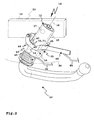
- An on-vehicle bracket 11 of a hitch 10 is attached or attachable, for example, to a cross member 12 of a towing vehicle 13, e.g. with not shown welded tabs or the like.
- a coupling arm 14 is inserted into a holding receptacle 15 of the holder 11.
- the coupling arm 14 is adjustably mounted on the holding receptacle 15 in two degrees of freedom of movement with respect to a movement axis 16, namely along the movement axis 16 linearly displaceable, which forms a longitudinal axis, and also pivotable about the movement axis 16, so that the movement axis 16 also forms a pivot axis.
- the coupling arm 14 of the hitch 10 is manually adjustable between the positions 22, 23, wherein alternatively motor drive concepts are possible.
- the holder is tubular or forms a holding tube into which a holding end 17 of the coupling arm 14 with a holding portion 18 is inserted.
- the coupling arm 14 is movably mounted between a working position 22 for attaching the trailer 21 and a rest position 23 to the bracket 11.
- the coupling end 19 projects to the rear in front of the towing vehicle 13, so that the trailer 21 can be coupled.
- the coupling arm 14 expediently pivots under a bumper 24, so that it is in the rest position 23 wholly or at least partially is located behind the bumper 24.
- the coupling arm 14 is then covered from view and damage and also does not affect the effectiveness of the bumper 24.
- the coupling arm 14 is in the working position 22 and in the rest position 23 by means of a locking device 25 on the holding receptacle 15 with respect to the movement axis 16 axially immovable and rotatably locked.
- a locking device 25 on the holding receptacle 15 with respect to the movement axis 16 axially immovable and rotatably locked.
- the holder 11 is designed like a tube.
- the guide portion 27 has a smaller inner cross-section than an adjoining, upper protective tube section 28.
- In the rest position 23 is the holding end 17 of the coupling arm 14 into the Protective tube section 28 before and is protected by this.
- In the working position 22, the coupling arm 14 is displaced axially out of the protective tube section 28 in the direction of the guide region 27.
- a holding-receiving stop 29 is formed, against which a coupling arm stop 30 of the coupling arm 14 strikes in the working position 22.
- the coupling arm stop 30 is formed by a coupling arm projection 31 at the holding end 17.
- the holding-receiving stop 29 extends over the entire inner circumference of the holding receptacle 15, so that the coupling arm projection 31 abuts in any case against the holding-receiving stop 29 and thus forms a pull-out lock 32.
- to form a pull-out lock would be sufficient if the coupling arm stop 30 protrudes radially at one point only in front of the outer periphery of the coupling arm 14.
- the coupling arm projection 31 is formed by a plate-like head piece 33, which is easy to install: the coupling arm 14 is inserted into the holding receptacle 15 and then the head end 33 by means of a screw 34 attached to the end face of the retaining end 17. It is understood that alternative fastening concepts, such as welding, in particular spot welding, or gluing are possible.
- the other components of the hitch 10, in particular the coupling arm 14 are inexpensive to manufacture. Nevertheless, the hitch 10 has a reliable and reliable operation and is easy to use.
- all movable components of the locking device 25 are arranged on the vehicle side in the region of the holder 11 or on the holder 11, while the coupling arm 14 has no movable components. It can be bent from a raw rod, as a casting, forging or the like mechanically high load capacity and yet produced low.
- the coupling arm 14 is not removable from the holder 11 (due to the pull-out lock 32). Nevertheless, the locking concept described below, the locking device 25 is also advantageously applicable to towing devices with detachable coupling arm 14:
- the locking device 25 contains interlocking elements 35 of a positive locking element arrangement 36, which are radially adjustable with respect to the coupling arm 14, wherein they engage in a locking position in positive locking receptacles 37 and 38 of a positive locking receiving arrangement 39.
- the interlocking elements 35 - it could also be provided only a positive locking element - are movably mounted on a form-locking element storage 73 of the holder 11 movable.
- the form-fitting receptacles 37 are the working position 22, the form-fitting receptacles 38 associated with the rest position 23.
- the interlocking elements 35 are formed by balls 40.
- the form-fitting receptacles 37 and 38 are present spherical caps, so that the balls 40 set the coupling arm 14 not only axially with respect to the axis of movement 16, but also in the direction of rotation.
- the rest position positive engagement receptacles 38 may be provided.
- other recording geometries such as a circumferential groove 89, in particular a ball seat channel, may be provided.
- the form-locking elements 35 are mounted axially movable in bearing recesses 41 of the form-locking element mounting 73.
- the bearing recesses 41 are e.g. provided on the holding receptacle 15, wherein a separate from the holding receptacle 15 and remote from this guide for the form-locking elements 35 would be possible.
- the bearing recesses 41 are, for example, bores 42 in the guide region 27.
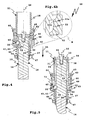
- the interlocking elements 35 are connected to an actuating ring 43 in a locking position, which in the FIGS. 4 and 5 becomes clear, adjustable.
- the actuating ring 43 forms an actuating device 100 for adjusting the interlocking elements 35 in the locking position.
- the actuating ring 43 is disposed on the outer circumference of the holder 11 and is penetrated by this.
- the actuating ring 43 is axially displaceable on the holder 11 and in the present case also rotatable.
- the energy accumulator 44 includes, for example, a spring 45, which is supported on a support projection 46 of the holder 11.
- the spring 45 is a coil spring which is penetrated by the holder 11.
- the support projection 46 is arranged in a lower, the coupling arm 14 facing end portion of the holder 11 and is presently formed by a support ring 47 which is screwed on the outside, for example, on the lower guide tube portion 26 outside. It is understood that the support ring 47, other types of attachment, such as welding or gluing, are possible. Furthermore, it is possible to replace the screwed Support ring 47, for example, provide an integrally formed on the bracket 11 support projection.
- the energy accumulator 44 acts on the actuating ring 43 in its locking position, in which the actuating ring 43 presses the interlocking elements 35 into the interlocking receptacles 38 or 38. Then the coupling arm 14 is locked to the bracket 11.
- the spring 45 limits the operating stroke of the actuating ring 43 in the unlocked position, so that the distance 49 is not so large that the balls 40 pass through it and can fall out of the hitch 10. Windings of the spring 45 are then packed tightly together and allow no further compression of the spring 45th
- the release area 48 extends conically obliquely and thus forms a catching area for the balls 40.
- a clamping area 52 for clamping the positive locking elements 35 into the positive locking seats 37 or 38 adjoins the release area 48. Although it would be sufficient in principle that the clamping area 52 has a smaller inner circumference than the release area 48 and in this respect the positive locking elements 35 in the direction the form-fitting receptacles 37, 38 is displaced over the entire adjustment range of the clamping region 52 of uniform force.
- a clamping bevel 53 is provided, which urges the balls 40 in the locking position.
- the clamping bevel 53 pushes the positive locking elements 35 by the force of the spring 45 in the bearing recesses 41 and thus in the form-fitting receptacles 37 or 38th
- the clamping bevel 53 advantageously has a flat, self-locking of the actuating ring 43 causing angle, e.g. 2-5 degrees, especially about 3 degrees.
- the clamping bevel 53 may optionally have a flat parallel to the adjustment axis of the actuating ring 43, in the case of the actuating ring 43, for example. cylindrical, holding section 53a be upstream.
- the interlocking elements 35 e.g. the balls 40, for example, under heavy load of the coupling arm 14, get out of the range of clamping bevel 53, it holds the holding portion 53 a still so deep in the form-fitting receptacles 37 that the coupling arm 14 reliably locked to the holding receptacle 15, although not braced is.
- the form-fitting receptacles 37 for the working position 22, which form working position-form-fitting recordings, also have inlet slopes 54.
- the inlet slopes 54 are inclined against the coupling arm stop 30 and act in the sense of a tensioning of the coupling arm 14 on the holding receptacle 15.
- the inlet slopes 54 also have an adjustment effect.
- the spring 45 acts directly on a lower end face 56 of the actuating ring 43. It is understood that in an alternative concept, an indirect force of an energy accumulator is possible, for example via a power transmission, a lever assembly or the like, which increases the force of the respective force accumulator.
- the bearing recesses 41 for the interlocking elements 35 are equidistant from each other. For example, they are offset by 120 ° to each other. Correlating to the form-fitting receptacles 37 and 38 are each arranged at 120 ° to each other rotational angle offset on the coupling arm 14. Thus, it is possible that the locking elements forming positive locking elements 35 once in the working position 22 and once in the rest position 23 in each case in the circumferential direction of the coupling arm 14 equally spaced form-fitting receptacles 37 or 38 engage, even if the coupling arm 14 between the positions 22, 23 is rotated.
- the form-fitting receptacles 37, 38 are spaced apart at a longitudinal distance 58. Further, they are rotationally offset from each other by a rotation angle 59, so that the coupling arm 14 a from the angular distance (120 °) of the form-fitting receptacles 37 or 38 each independent pivot angle, i. more or less than the positive locking angular distance, between the working position 22 and the rest position 23 can pivot, for. about 90 ° to 100 ° or 130-150 degrees.
- the coupling arm 14 is safe and in particular under load, e.g. when attached, locked without play.
- the relatively strong spring 45 ensures a compensation, so that any vibrations caused by the trailer load of the coupling arm 14 are compensated at the holding receptacle 15.
- the spring 45 acts on the locking device 25sachstellend.
- the interlocking elements 35 automatically latch into the positive-locking receptacles 37 or 38.
- a reliable lock is audible and seen at the longitudinal position of the actuating ring 43.
- the correct locking position of the actuating ring 43 may be characterized by an optical marking.
- the unlocking of the locking device 25 is designed simply. With an actuating lever 60, the actuating ring 43 are operated with relatively low operating force.
- the operating lever 60 is pivotally mounted on the bracket 11.
- a bearing holder 61 is arranged, for example, a U-shaped holding part with two holding legs.
- the bearing holder 61 holds a bearing pin 62, the bearing pin ends 63 protrude laterally in front of the bearing holder 61.
- At the bearing pin ends 63 of the actuating lever 60 is pivotally mounted.
- the bearing pin ends 63 penetrate bearing openings or sockets 64 on actuating lever arms 65 of the actuating lever 60.
- the actuating lever 60 engages around the holder 11. Operating portions 67 of the lever arms 65 extend laterally outwardly past the holder 11 at a distance such that actuating shoulders 68 on the underside of the lever arms 65 can act on the upper end face of the actuating ring 43. Thus, the operating lever 60 acts uniformly on the actuating ring 43 from two sides.
- the lever arms 65 are approximately U-shaped in the region of the actuating sections 67, the bearing openings 64 being arranged at one leg end, the lower U section having the actuating shoulders 68 and the other U leg extending to the respective other lever arm 65 extending into a handle section 69 passes.
- the lever arms 65 are on the handle portion 69 connected to each other, for example, by screws, not shown or welded together. It is understood that for convenient gripping a handpiece can be arranged on the handle portion of the actuating lever 60, for example made of plastic.
- the actuating lever arms 65 are advantageously made of metal, for example stamped and bent parts.
- the actuating shoulders 68 slide along the top of the actuating ring 43.
- the actuating lever 60 is decoupled from the actuating ring 43 movable.
- the actuating lever 60 when not in use little or no play and is rattle-free, so to speak:
- the force accumulator 44 presses the operating lever 60 against stops 70 via the actuating ring 43, which protrude laterally, for example, in the region of the actuating sections 67 in front of the holder 11.
- the stops 70 are formed, for example, by bolts 71 screwed into the protective pipe section 28.
- the actuating portions 67 have recesses 72 into which the bolts 71 can engage.
- the balls 40 in connection with the Kalotten-Form gleichingn 37 act as anti-rotation for the coupling arm 14.
- the positive locking contours 75, 76 are brought into engagement or disengaged.
- the release area 48 and the clamping area 52 are configured as conically extending annular grooves.
- actuating and releasing the interlocking elements 35 but also extending in the direction of actuation of the respective actuating ring longitudinal grooves are possible, for example, axial grooves 77 at an actuating ring 43b or helical or oblique longitudinal grooves 78 in an actuating ring 43c.
- actuating ring 43c is e.g. a force accumulator which causes a rotational locking movement, e.g. a arranged in the manner of the spring 45, but instead designed as a compression spring as a torsion spring which is rotatably connected to the actuating ring 43c.
- the pressure spring 45 can serve as energy storage.
- springs or spring 91 ( FIG. 8c ) possible, which serve as a self-locking force storage 90 of a locking device.
- the spring stores 91 engage tangentially on the outer circumference, For example, from projections 94, or an end face of the actuating ring 43c and are clamped at its release to pressure or train with respect to stationary counter-positions 92, which are arranged for example on a vehicle-side bracket 93 for a coupling arm, not shown.
- An alternative unlocking concept for the actuating ring 43 may be, for example, a pulling device, e.g. a schematically illustrated Bowden cable 79, provide, which acts directly on the actuating ring 43.
- An actuating end of the Bowden cable 79 is arranged, for example, in the interior of the traction vehicle 13, for example in the trunk.
- a Bowden cable 80 for actuating the operating lever 60 is expediently actuated from the interior of the tractor 13 from. It will be appreciated that the operating ends of the Bowden cables 79 or 80 may also be conveniently gripped by an operator at the front or top of the bumper 24, for example.
- FIG. 9 is also schematically an electric Entriegelungsantrieb 81 indicated in a hitch 10 '.
- the unlocking drive 81 includes an electromagnet 82, which displaces the actuating ring 43 in the unlocked position when energized via an actuating rod 83.
- the solenoid 82 is de-energized and thus unconfirmed, the control rod 83 is free to move, so that the energy storage device 44 cantechnischverstellen the actuating ring 43 back into its locking position.
- An alternative energy store 44 ' is, for example, a pneumatic force store 84 with a pneumatic cylinder 85, in the interior of which there is air or another gaseous medium, which is compressed upon actuation of the actuating ring 43 in its unlocked position and has the tendency to move a piston rod 86 back out of the cylinder housing.
- the piston rod 86 acts on the actuating ring 43 and thus returns it to its locking position.
- the actuating ring 43 is operated directly by hand in a simplified construction.
- the movement is simplified when the actuating ring 43, for example, a handle 87 is arranged, which is convenient to grasp.
- the handle 87 is suitably laterally, in particular obliquely downward before the actuating ring 43 before.
- the movement axis 16 is inclined to the vertical. As a result, a movement of the coupling arm 14 with low ground clearance of the towing vehicle 13 is possible. It is understood that the functional principle according to the invention is also possible for towing devices with axes of movement in other angular positions, for example in vertical or vertical axes of movement.
Applications Claiming Priority (2)
| Application Number | Priority Date | Filing Date | Title |
|---|---|---|---|
| DE200610044341 DE102006044341A1 (de) | 2006-09-18 | 2006-09-18 | Anhängerkupplung |
| DE200710003773 DE102007003773A1 (de) | 2007-01-19 | 2007-01-19 | Anhängevorrichtung für ein Zugfahrzeug |
Publications (2)
| Publication Number | Publication Date |
|---|---|
| EP1902870A1 EP1902870A1 (de) | 2008-03-26 |
| EP1902870B1 true EP1902870B1 (de) | 2009-11-11 |
Family
ID=38691854
Family Applications (2)
| Application Number | Title | Priority Date | Filing Date |
|---|---|---|---|
| EP07400022A Expired - Fee Related EP1902871B2 (de) | 2006-09-18 | 2007-09-14 | Anhängekupplung |
| EP20070400021 Active EP1902870B1 (de) | 2006-09-18 | 2007-09-14 | Anhängevorrichtung für ein Zugfahrzeug |
Family Applications Before (1)
| Application Number | Title | Priority Date | Filing Date |
|---|---|---|---|
| EP07400022A Expired - Fee Related EP1902871B2 (de) | 2006-09-18 | 2007-09-14 | Anhängekupplung |
Country Status (2)
| Country | Link |
|---|---|
| EP (2) | EP1902871B2 (zh) |
| DE (2) | DE502007001954D1 (zh) |
Cited By (6)
| Publication number | Priority date | Publication date | Assignee | Title |
|---|---|---|---|---|
| US10670479B2 (en) | 2018-02-27 | 2020-06-02 | Methode Electronics, Inc. | Towing systems and methods using magnetic field sensing |
| US10696109B2 (en) | 2017-03-22 | 2020-06-30 | Methode Electronics Malta Ltd. | Magnetolastic based sensor assembly |
| US11084342B2 (en) | 2018-02-27 | 2021-08-10 | Methode Electronics, Inc. | Towing systems and methods using magnetic field sensing |
| US11135882B2 (en) | 2018-02-27 | 2021-10-05 | Methode Electronics, Inc. | Towing systems and methods using magnetic field sensing |
| US11221262B2 (en) | 2018-02-27 | 2022-01-11 | Methode Electronics, Inc. | Towing systems and methods using magnetic field sensing |
| US11491832B2 (en) | 2018-02-27 | 2022-11-08 | Methode Electronics, Inc. | Towing systems and methods using magnetic field sensing |
Families Citing this family (6)
| Publication number | Priority date | Publication date | Assignee | Title |
|---|---|---|---|---|
| EP2121240B1 (en) | 2007-01-15 | 2017-05-10 | PHD, Inc. | Armover clamp assembly |
| DE102011053506A1 (de) * | 2011-09-12 | 2013-03-14 | Scambia Holdings Cyprus Ltd. | Anhängekupplung |
| DE102013018735A1 (de) * | 2013-11-08 | 2015-05-13 | Westfalia-Automotive Gmbh | Anhängekupplung mit einer Fixiereinrichtung |
| US11577561B2 (en) | 2017-12-20 | 2023-02-14 | Horizon Global (South Africa) (Pty) Ltd | Towbar with a hitch ball system |
| SE544412C2 (en) * | 2019-03-12 | 2022-05-10 | Brink Towing Systems B V | Retractable towing hook arrangement |
| DE102020114230A1 (de) | 2020-05-27 | 2021-12-02 | ACPS Automotive GmbH | Anhängevorrichtung |
Family Cites Families (16)
| Publication number | Priority date | Publication date | Assignee | Title |
|---|---|---|---|---|
| DE2935474C2 (de) | 1979-09-01 | 1982-04-29 | Daimler-Benz Ag, 7000 Stuttgart | Anhängevorrichtung, insbesondere für Personenkraftwagen. |
| DE3328524A1 (de) * | 1983-08-06 | 1985-02-21 | Daimler-Benz Ag, 7000 Stuttgart | Anhaengerkupplung fuer fahrzeuge |
| US5356166A (en) * | 1993-07-12 | 1994-10-18 | Automatic Equipment Mfg. Co. | Arrestably lockable telescoping tow-bar assembly |
| DE19826618C2 (de) † | 1998-06-17 | 2001-05-03 | Peter Rocca | Anhängekupplung |
| DE19859961C2 (de) | 1998-12-29 | 2003-07-03 | Westfalia Automotive Gmbh & Co | Anhängerkupplung mit einem schwenkbaren Kugelhals |
| DE19944264A1 (de) | 1999-09-15 | 2001-03-22 | Jaeger Cartronix Gmbh | Anhängerkupplung mit axialem Verfahrweg |
| EP1090782A3 (de) * | 1999-10-04 | 2002-02-06 | PEKA-Fahrzeugbau GmbH & Co. KG | Anhängerkupplung für Kraftfahrzeuge |
| DE10004523A1 (de) * | 2000-02-02 | 2001-08-09 | Fac Frank Abels Consult & Tech | Anhängerkupplung |
| DE10017013A1 (de) † | 2000-04-05 | 2001-10-18 | Oris Fahrzeugteile Riehle H | Anhängekupplung |
| DE10243044B4 (de) * | 2002-09-12 | 2016-01-21 | Westfalia-Automotive Gmbh | Anhängerkupplung |
| DE10243045B4 (de) * | 2002-09-12 | 2016-01-21 | Westfalia-Automotive Gmbh | Anhängerkupplung |
| EP1407901B2 (de) * | 2002-10-09 | 2012-10-03 | AL-KO Kober AG | Anhängevorrichtung für Zugfahrzeuge |
| DE10327706B3 (de) * | 2003-06-20 | 2005-02-17 | Westfalia-Automotive Gmbh & Co. Kg | Hilfskraftbetätigte Anhängekupplung für Kraftfahrzeuge |
| DE10355490A1 (de) * | 2003-11-27 | 2005-08-11 | Westfalia-Automotive Gmbh & Co. Kg | Anhängerkupplung |
| DE102004004503B4 (de) * | 2004-01-22 | 2022-01-20 | ACPS Automotive GmbH | Anhängekupplung |
| DE202006009230U1 (de) * | 2006-06-09 | 2006-08-10 | Fac Gmbh | Anhängerkupplung |
-
2007
- 2007-09-14 EP EP07400022A patent/EP1902871B2/de not_active Expired - Fee Related
- 2007-09-14 EP EP20070400021 patent/EP1902870B1/de active Active
- 2007-09-14 DE DE200750001954 patent/DE502007001954D1/de active Active
- 2007-09-14 DE DE200750001779 patent/DE502007001779D1/de active Active
Cited By (7)
| Publication number | Priority date | Publication date | Assignee | Title |
|---|---|---|---|---|
| US10696109B2 (en) | 2017-03-22 | 2020-06-30 | Methode Electronics Malta Ltd. | Magnetolastic based sensor assembly |
| US10940726B2 (en) | 2017-03-22 | 2021-03-09 | Methode Electronics Malta Ltd. | Magnetoelastic based sensor assembly |
| US10670479B2 (en) | 2018-02-27 | 2020-06-02 | Methode Electronics, Inc. | Towing systems and methods using magnetic field sensing |
| US11084342B2 (en) | 2018-02-27 | 2021-08-10 | Methode Electronics, Inc. | Towing systems and methods using magnetic field sensing |
| US11135882B2 (en) | 2018-02-27 | 2021-10-05 | Methode Electronics, Inc. | Towing systems and methods using magnetic field sensing |
| US11221262B2 (en) | 2018-02-27 | 2022-01-11 | Methode Electronics, Inc. | Towing systems and methods using magnetic field sensing |
| US11491832B2 (en) | 2018-02-27 | 2022-11-08 | Methode Electronics, Inc. | Towing systems and methods using magnetic field sensing |
Also Published As
| Publication number | Publication date |
|---|---|
| EP1902871B1 (de) | 2009-10-21 |
| EP1902871B2 (de) | 2012-11-28 |
| EP1902871A1 (de) | 2008-03-26 |
| DE502007001954D1 (de) | 2009-12-24 |
| DE502007001779D1 (de) | 2009-12-03 |
| EP1902870A1 (de) | 2008-03-26 |
Similar Documents
| Publication | Publication Date | Title |
|---|---|---|
| EP1902870B1 (de) | Anhängevorrichtung für ein Zugfahrzeug | |
| EP2277724B1 (de) | Anhängekupplung | |
| EP2792514B1 (de) | Anhängekupplung | |
| EP1946947B1 (de) | Anhängevorrichtung mit einer Verriegelungseinrichtung mit Betätigungsring | |
| EP2474430B1 (de) | Anhängekupplung | |
| EP2792513B1 (de) | Anhängekupplung | |
| DE102013018771A1 (de) | Anhängekupplung mit einer Trägeranordnung | |
| EP3098094B1 (de) | Anhängekupplung mit einem schwenklager | |
| EP2799261B1 (de) | Anhängekupplung | |
| EP3098096B1 (de) | Anhängekupplung mit einer fixiereinrichtung | |
| DE102007003773A1 (de) | Anhängevorrichtung für ein Zugfahrzeug | |
| EP2316673B1 (de) | Verbindungseinrichtung für eine Anhängekupplung oder einen Lastenträger | |
| DE102013018735A1 (de) | Anhängekupplung mit einer Fixiereinrichtung | |
| DE102014005881A1 (de) | Anhängekupplung | |
| DE102016109939A1 (de) | Anhängekupplung | |
| EP2796304B1 (de) | Anhängekupplung | |
| EP2796303B1 (de) | Anhängekupplung | |
| EP2796305B1 (de) | Anhängekupplung | |
| EP3012128B1 (de) | Kupplungsvorrichtung mit einer fixiereinrichtung | |
| EP3098095B1 (de) | Anhängekupplung mit einer fixiereinrichtung | |
| DE102013007123A1 (de) | Anhängekupplung |
Legal Events
| Date | Code | Title | Description |
|---|---|---|---|
| PUAI | Public reference made under article 153(3) epc to a published international application that has entered the european phase |
Free format text: ORIGINAL CODE: 0009012 |
|
| AK | Designated contracting states |
Kind code of ref document: A1 Designated state(s): AT BE BG CH CY CZ DE DK EE ES FI FR GB GR HU IE IS IT LI LT LU LV MC MT NL PL PT RO SE SI SK TR |
|
| AX | Request for extension of the european patent |
Extension state: AL BA HR MK YU |
|
| 17P | Request for examination filed |
Effective date: 20080916 |
|
| AKX | Designation fees paid |
Designated state(s): DE FR |
|
| GRAP | Despatch of communication of intention to grant a patent |
Free format text: ORIGINAL CODE: EPIDOSNIGR1 |
|
| GRAS | Grant fee paid |
Free format text: ORIGINAL CODE: EPIDOSNIGR3 |
|
| GRAA | (expected) grant |
Free format text: ORIGINAL CODE: 0009210 |
|
| AK | Designated contracting states |
Kind code of ref document: B1 Designated state(s): DE FR |
|
| REF | Corresponds to: |
Ref document number: 502007001954 Country of ref document: DE Date of ref document: 20091224 Kind code of ref document: P |
|
| PLBE | No opposition filed within time limit |
Free format text: ORIGINAL CODE: 0009261 |
|
| STAA | Information on the status of an ep patent application or granted ep patent |
Free format text: STATUS: NO OPPOSITION FILED WITHIN TIME LIMIT |
|
| 26N | No opposition filed |
Effective date: 20100812 |
|
| REG | Reference to a national code |
Ref country code: DE Ref legal event code: R082 Ref document number: 502007001954 Country of ref document: DE Representative=s name: BREGENZER, MICHAEL, DIPL.-ING., DE Ref country code: DE Ref legal event code: R082 Ref document number: 502007001954 Country of ref document: DE Representative=s name: PATENTANWAELTE BREGENZER UND REULE PARTNERSCHA, DE |
|
| REG | Reference to a national code |
Ref country code: DE Ref legal event code: R082 Ref document number: 502007001954 Country of ref document: DE Representative=s name: PATENTANWAELTE BREGENZER UND REULE PARTNERSCHA, DE |
|
| REG | Reference to a national code |
Ref country code: FR Ref legal event code: PLFP Year of fee payment: 9 |
|
| REG | Reference to a national code |
Ref country code: FR Ref legal event code: PLFP Year of fee payment: 10 |
|
| REG | Reference to a national code |
Ref country code: FR Ref legal event code: PLFP Year of fee payment: 11 |
|
| REG | Reference to a national code |
Ref country code: FR Ref legal event code: PLFP Year of fee payment: 12 |
|
| PGFP | Annual fee paid to national office [announced via postgrant information from national office to epo] |
Ref country code: FR Payment date: 20210719 Year of fee payment: 15 |
|
| PG25 | Lapsed in a contracting state [announced via postgrant information from national office to epo] |
Ref country code: FR Free format text: LAPSE BECAUSE OF NON-PAYMENT OF DUE FEES Effective date: 20220930 |
|
| PGFP | Annual fee paid to national office [announced via postgrant information from national office to epo] |
Ref country code: DE Payment date: 20230927 Year of fee payment: 17 |