EP1829592A1 - Linear motor driven amusement ride and method - Google Patents
Linear motor driven amusement ride and method Download PDFInfo
- Publication number
- EP1829592A1 EP1829592A1 EP07250876A EP07250876A EP1829592A1 EP 1829592 A1 EP1829592 A1 EP 1829592A1 EP 07250876 A EP07250876 A EP 07250876A EP 07250876 A EP07250876 A EP 07250876A EP 1829592 A1 EP1829592 A1 EP 1829592A1
- Authority
- EP
- European Patent Office
- Prior art keywords
- vehicle
- sliding surface
- linear
- sliding
- amusement ride
- Prior art date
- Legal status (The legal status is an assumption and is not a legal conclusion. Google has not performed a legal analysis and makes no representation as to the accuracy of the status listed.)
- Granted
Links
- 238000000034 method Methods 0.000 title claims description 20
- 230000033001 locomotion Effects 0.000 claims abstract description 32
- 230000006698 induction Effects 0.000 claims abstract description 29
- XLYOFNOQVPJJNP-UHFFFAOYSA-N water Substances O XLYOFNOQVPJJNP-UHFFFAOYSA-N 0.000 claims description 24
- 230000001360 synchronised effect Effects 0.000 claims description 5
- 229910052782 aluminium Inorganic materials 0.000 description 5
- XAGFODPZIPBFFR-UHFFFAOYSA-N aluminium Chemical compound [Al] XAGFODPZIPBFFR-UHFFFAOYSA-N 0.000 description 5
- 239000000463 material Substances 0.000 description 5
- 229910000831 Steel Inorganic materials 0.000 description 3
- 230000001965 increasing effect Effects 0.000 description 3
- 238000005461 lubrication Methods 0.000 description 3
- 239000010959 steel Substances 0.000 description 3
- 241000555745 Sciuridae Species 0.000 description 2
- 238000013459 approach Methods 0.000 description 2
- 238000001816 cooling Methods 0.000 description 2
- 230000000694 effects Effects 0.000 description 2
- 239000011152 fibreglass Substances 0.000 description 2
- 230000005484 gravity Effects 0.000 description 2
- 238000012986 modification Methods 0.000 description 2
- 230000004048 modification Effects 0.000 description 2
- 230000001095 motoneuron effect Effects 0.000 description 2
- 238000011144 upstream manufacturing Methods 0.000 description 2
- RYGMFSIKBFXOCR-UHFFFAOYSA-N Copper Chemical compound [Cu] RYGMFSIKBFXOCR-UHFFFAOYSA-N 0.000 description 1
- 229910001335 Galvanized steel Inorganic materials 0.000 description 1
- XEEYBQQBJWHFJM-UHFFFAOYSA-N Iron Chemical group [Fe] XEEYBQQBJWHFJM-UHFFFAOYSA-N 0.000 description 1
- 239000004809 Teflon Substances 0.000 description 1
- 230000001133 acceleration Effects 0.000 description 1
- 239000011248 coating agent Substances 0.000 description 1
- 238000000576 coating method Methods 0.000 description 1
- 229910052802 copper Inorganic materials 0.000 description 1
- 239000010949 copper Substances 0.000 description 1
- 230000004907 flux Effects 0.000 description 1
- 238000009432 framing Methods 0.000 description 1
- 239000008397 galvanized steel Substances 0.000 description 1
- 239000011521 glass Substances 0.000 description 1
- 239000003365 glass fiber Substances 0.000 description 1
- 230000001939 inductive effect Effects 0.000 description 1
- 239000000314 lubricant Substances 0.000 description 1
- 229910052751 metal Inorganic materials 0.000 description 1
- 239000002184 metal Substances 0.000 description 1
- 229920005989 resin Polymers 0.000 description 1
- 239000011347 resin Substances 0.000 description 1
- 238000005096 rolling process Methods 0.000 description 1
- 125000000391 vinyl group Chemical group [H]C([*])=C([H])[H] 0.000 description 1
- 229920002554 vinyl polymer Polymers 0.000 description 1
- 238000004804 winding Methods 0.000 description 1
Images


Classifications
-
- A—HUMAN NECESSITIES
- A63—SPORTS; GAMES; AMUSEMENTS
- A63G—MERRY-GO-ROUNDS; SWINGS; ROCKING-HORSES; CHUTES; SWITCHBACKS; SIMILAR DEVICES FOR PUBLIC AMUSEMENT
- A63G21/00—Chutes; Helter-skelters
- A63G21/18—Water-chutes
-
- A—HUMAN NECESSITIES
- A63—SPORTS; GAMES; AMUSEMENTS
- A63G—MERRY-GO-ROUNDS; SWINGS; ROCKING-HORSES; CHUTES; SWITCHBACKS; SIMILAR DEVICES FOR PUBLIC AMUSEMENT
- A63G21/00—Chutes; Helter-skelters
- A63G21/12—Chutes; Helter-skelters with special cars, e.g. horse-shaped
-
- A—HUMAN NECESSITIES
- A63—SPORTS; GAMES; AMUSEMENTS
- A63G—MERRY-GO-ROUNDS; SWINGS; ROCKING-HORSES; CHUTES; SWITCHBACKS; SIMILAR DEVICES FOR PUBLIC AMUSEMENT
- A63G21/00—Chutes; Helter-skelters
-
- A—HUMAN NECESSITIES
- A63—SPORTS; GAMES; AMUSEMENTS
- A63G—MERRY-GO-ROUNDS; SWINGS; ROCKING-HORSES; CHUTES; SWITCHBACKS; SIMILAR DEVICES FOR PUBLIC AMUSEMENT
- A63G21/00—Chutes; Helter-skelters
- A63G21/02—Chutes; Helter-skelters without rails
-
- A—HUMAN NECESSITIES
- A63—SPORTS; GAMES; AMUSEMENTS
- A63G—MERRY-GO-ROUNDS; SWINGS; ROCKING-HORSES; CHUTES; SWITCHBACKS; SIMILAR DEVICES FOR PUBLIC AMUSEMENT
- A63G21/00—Chutes; Helter-skelters
- A63G21/06—Chutes; Helter-skelters with passing arrangements for cars
-
- A—HUMAN NECESSITIES
- A63—SPORTS; GAMES; AMUSEMENTS
- A63G—MERRY-GO-ROUNDS; SWINGS; ROCKING-HORSES; CHUTES; SWITCHBACKS; SIMILAR DEVICES FOR PUBLIC AMUSEMENT
- A63G21/00—Chutes; Helter-skelters
- A63G21/14—Chutes; Helter-skelters with driven slideways
-
- A—HUMAN NECESSITIES
- A63—SPORTS; GAMES; AMUSEMENTS
- A63G—MERRY-GO-ROUNDS; SWINGS; ROCKING-HORSES; CHUTES; SWITCHBACKS; SIMILAR DEVICES FOR PUBLIC AMUSEMENT
- A63G3/00—Water roundabouts, e.g. freely floating
- A63G3/02—Water roundabouts, e.g. freely floating with floating seats
-
- A—HUMAN NECESSITIES
- A63—SPORTS; GAMES; AMUSEMENTS
- A63G—MERRY-GO-ROUNDS; SWINGS; ROCKING-HORSES; CHUTES; SWITCHBACKS; SIMILAR DEVICES FOR PUBLIC AMUSEMENT
- A63G7/00—Up-and-down hill tracks; Switchbacks
-
- B—PERFORMING OPERATIONS; TRANSPORTING
- B60—VEHICLES IN GENERAL
- B60L—PROPULSION OF ELECTRICALLY-PROPELLED VEHICLES; SUPPLYING ELECTRIC POWER FOR AUXILIARY EQUIPMENT OF ELECTRICALLY-PROPELLED VEHICLES; ELECTRODYNAMIC BRAKE SYSTEMS FOR VEHICLES IN GENERAL; MAGNETIC SUSPENSION OR LEVITATION FOR VEHICLES; MONITORING OPERATING VARIABLES OF ELECTRICALLY-PROPELLED VEHICLES; ELECTRIC SAFETY DEVICES FOR ELECTRICALLY-PROPELLED VEHICLES
- B60L13/00—Electric propulsion for monorail vehicles, suspension vehicles or rack railways; Magnetic suspension or levitation for vehicles
- B60L13/03—Electric propulsion by linear motors
-
- B—PERFORMING OPERATIONS; TRANSPORTING
- B61—RAILWAYS
- B61B—RAILWAY SYSTEMS; EQUIPMENT THEREFOR NOT OTHERWISE PROVIDED FOR
- B61B13/00—Other railway systems
- B61B13/08—Sliding or levitation systems
-
- H—ELECTRICITY
- H02—GENERATION; CONVERSION OR DISTRIBUTION OF ELECTRIC POWER
- H02K—DYNAMO-ELECTRIC MACHINES
- H02K41/00—Propulsion systems in which a rigid body is moved along a path due to dynamo-electric interaction between the body and a magnetic field travelling along the path
- H02K41/02—Linear motors; Sectional motors
- H02K41/025—Asynchronous motors
-
- A—HUMAN NECESSITIES
- A63—SPORTS; GAMES; AMUSEMENTS
- A63G—MERRY-GO-ROUNDS; SWINGS; ROCKING-HORSES; CHUTES; SWITCHBACKS; SIMILAR DEVICES FOR PUBLIC AMUSEMENT
- A63G21/00—Chutes; Helter-skelters
- A63G21/08—Chutes; Helter-skelters with additional rotation of cars
-
- A—HUMAN NECESSITIES
- A63—SPORTS; GAMES; AMUSEMENTS
- A63G—MERRY-GO-ROUNDS; SWINGS; ROCKING-HORSES; CHUTES; SWITCHBACKS; SIMILAR DEVICES FOR PUBLIC AMUSEMENT
- A63G21/00—Chutes; Helter-skelters
- A63G21/16—Chutes; Helter-skelters with forced removal of the passenger from the seat
-
- H—ELECTRICITY
- H02—GENERATION; CONVERSION OR DISTRIBUTION OF ELECTRIC POWER
- H02K—DYNAMO-ELECTRIC MACHINES
- H02K7/00—Arrangements for handling mechanical energy structurally associated with dynamo-electric machines, e.g. structural association with mechanical driving motors or auxiliary dynamo-electric machines
- H02K7/14—Structural association with mechanical loads, e.g. with hand-held machine tools or fans
Definitions
- This invention relates generally to amusement rides, and in particular to rides in which participants ride in or on vehicles.
- the most common water-based amusement rides are flume-style waterslides in which a participant slides along a channel or "flume", either on his or her body, or on or in a vehicle. Water is provided in the flume to provide lubrication between the body/vehicle and the flume surface, and to provide the above-mentioned cooling and splashing effects.
- the motion of the participant in the flume is controlled predominantly by the contours of the flume (hills, valleys, turns, drops, etc.) in combination with gravity.
- the invention provides an amusement ride feature comprising a sliding surface, a vehicle adapted to slide on said sliding surface and to convey at least one rider thereon; and a linear motor associated with the vehicle and the sliding surface for affecting sliding motion of the vehicle on the sliding surface.
- the invention provides an amusement ride which includes a feature comprising a sliding surface, a vehicle adapted to slide on said sliding surface and to convey at least one rider thereon, and a linear motor associated with the vehicle and the sliding surface for affecting sliding motion of the vehicle on the sliding surface.
- the invention provides a method of controlling the sliding motion of a vehicle sliding on a sliding surface in an amusement ride, comprising operating a linear motor associated with the vehicle and the sliding surface.
- the invention provides a method of controlling the sliding motion of a vehicle sliding on a sliding surface in an amusement ride, comprising providing the sliding surface, placing the vehicle on the sliding surface, and operating a linear motor associated with the vehicle and the sliding surface.
- the invention provides an amusement ride sliding surface for bearing a vehicle in sliding relationship thereto, said vehicle conveying at least one rider and having affixed thereto at least one reaction component, said sliding surface having located therebeneath, a plurality of linear induction motor units for interacting with the at least one reaction component affixed to the vehicle to affect sliding motion of the vehicle on the sliding surface.
- the invention provides an amusement ride vehicle adapted to slide on an amusement ride sliding surface and to convey at least one rider thereon, said vehicle having affixed thereto at least one reaction plate for interacting with linear induction motor units associated with the sliding surface to affect sliding motion of the vehicle on the sliding surface.
- the sliding surface may be a waterslide and may be flume-style.
- the linear motor may comprise a reaction plate mounted at a bottom of the vehicle as well as linear induction motor units mounted below the sliding surface.
- the present invention is directed to amusement rides in which participants ride in vehicles which slide on a sliding surface.
- sliding refers to the action of moving substantially smoothly along a weight-bearing sliding surface while remaining substantially in contact with it. This is in contrast to “rolling” which refers to the action of moving along a weight bearing surface by the relative rotation of wheels, rollers, bearings, etc..
- sliding is typically facilitated by the use of water as a lubricant between the vehicle and the sliding surface.
- water as a lubricant between the vehicle and the sliding surface.
- direct contact between the vehicle and the flume may be lost very briefly and temporarily with the vehicle skimming atop a very thin layer of water.
- temporary skimming is still considered to fall within the meaning of sliding in the waterslide context.
- Flume-style waterslides typically comprise a channel or "flume” supplied with water and which accommodates a vehicle for sliding therein.
- the flume typically has hills and valleys as well as turns to increase the excitement of the ride for the participant. While the amusement ride described below is a flume-style waterslide, it is to be understood that in a broad sense, the invention relates to amusement rides generally.
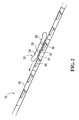
- Figure 1 shows an exemplary uphill section of such a flume 10 in accordance with a first embodiment of the invention, in which the vehicle would normally move from the right to the left.
- the illustrated section is connected at its entry 12 and exit 14 ends to other sections of the flume ride so as to provide a continuous flume from start to finish of the ride.
- the illustrated section would also normally be supported underneath by appropriate framing (not shown), or by a sloped section of land (not shown).
- a sliding surface 16 of the flume has been removed, such that elements located beneath this sliding surface 16 can be seen.
- the flume 10 itself is generally comprised of the above-mentioned sliding surface 16 (removed in Figure 1 to illustrates components therebeneath), as well as two side walls 18 (removed in Figure 2 to show the vehicle 20).
- the sliding surface 16 is the surface on which the vehicle 20 slides, while the side walls 18 assist in ensuring that the vehicle 20 remains in the flume 10.
- the sliding surface 16 and side walls 18 may be made of any material providing sufficient toughness and rigidity, and may be smooth so as to permit easy sliding of the vehicle 20 thereon.
- the sliding surface 16 and side walls 18 are made of fiberglass, and in particular a combination of neo-isothalic gelcoat, chop strand E-Glass or S-Glass fiber, woven roving and isothalic and orthothalic resins.
- the vehicle 20 is a raft adapted to carry one or more riders thereon and is provided at its bottom with a vehicle bottom surface 22 adapted to slide along the sliding surface 16 of the flume 10 during normal operation.
- the vehicle 20 in this embodiment has side tubes 24, thwarts 26 and handles 28.
- Means are provided to impart a thrusting force to the vehicle 20 to assist it up the illustrated uphill section of the flume 10.
- a thrusting force is desirable for example where the speed of the vehicle 20 arriving at the entry end 12 of the illustrated section from other parts of the flume ride is not sufficient to propel the vehicle 20 to the exit end 14 of the illustrated section at a desired speed, on the basis of the vehicle's momentum alone.
- the illustrated flume section 10 has been provided with a linear motor.
- linear motors including linear induction motors (LIMs) and linear synchronous motors, suitable for the present application.
- LIMs linear induction motors
- linear synchronous motors suitable for the present application.
- the exemplary linear motor used in the illustrated embodiment is a squirrel cage style linear induction motor.
- the linear induction motor of this embodiment is a standard rotary squirrel cage motor which has been opened out flat with the stator units lying in a spaced linear configuration and the rotor being replaced by a substantially flat reaction plate.
- the rotor may be replaced by other elements, a curved reaction plate, an electromagnet, or a permanent magnet, for example.
- the units of the stator known as linear induction motor units ("LIM units") when laid out flat, each comprise a 3 phase winding around a laminated iron core.
- LIM units linear induction motor units
- AC alternating current
- the reaction component or plate in such LIMs is typically a sheet of any electrically conductive metal, for example aluminum or copper.
- the conducting sheet may be backed by steel to provide return paths for the stator's magnetic flux.
- Currents induced in the reaction plate by the LIM units' travelling field create a secondary magnetic field. It is the reaction between these two magnetic fields which imparts the linear thrust to the reaction plate.
- the magnitude of the thrust imparted to the reaction plate is controlled largely by the voltage and frequency of the electrical supply to the LIM units (as supplied by an inverter, not shown) and the dimensions and materials of the reaction plate. Thrust of the LIM can be reversed if the polarity is changed on the LIM units.
- a LIM can control various aspects of the motion of a vehicle to which the reaction plate is affixed, depending on the configuration of the LIM units and the shape of the reaction plate. For example, the LIM can accelerate or decelerate the vehicle. It can also maintain the speed of the vehicle as it proceeds up an incline, or cause it to turn around corners. If the reaction plate is circular, it can also cause the vehicle to rotate.
- the LIM units 30 are located under the sliding surface 16 of the flume 10 in spaced linear relationship in the direction of travel of the ride vehicle 20, and the reaction plate 32 is mounted at the bottom of the vehicle 20.
- each LIM unit 30 of this embodiment is rectangular in shape and is substantially flat.
- the dimensions of each LIM unit are 500mm in length, 250mm in width, and 85mm in height and provides a thrust of 600N at 480V, 60Hz AC current and 20% duty cycle.
- 600N 600N at 480V, 60Hz AC current and 20% duty cycle.
- other dimensions, other voltages, other frequencies and other duty cycles may be used to provide a required thrust.
- the LIM units 30 are mounted longitudinally to a flume frame 34 such that they are located just beneath the sliding surface 16 and substantially centered between the side walls 18.
- An upper surface of the LIM units 30 may alternatively form part of, or the entirety of the sliding surface 16. In either case, the functioning portions of the LIM units 30 are located beneath the sliding surface 16.
- each LIM unit 30 is spaced from adjacent LIM units 30. In this embodiment, the LIM units 30 are spaced 571.5mm apart.
- the LIM units 30 are electrically connected to a controlled power supply 36.
- the reaction plate 32 is substantially flat and oblong in this embodiment. In other embodiments, other shapes of reaction plate 32 may be used, elliptical, round or square for example.
- the reaction plate 32 is a 1/8" sheet of 1050, 1100, 1200 or 5005 aluminum and a 3/32" sheet of A36 galvanized steel affixed above the sheet of aluminum.
- the reaction plate 32 is 72" in length and 18" in width, with the width of the steel sheet being 2" narrower than the aluminum sheet such that the aluminum sheet extends beyond the width of the steel sheet by 2" on each side. Examples of suitable reaction plates are detailed in a co-owned application entitled "Reaction Component for a Linear Induction Motor", filed concurrently with the present application and incorporated herein by reference in its entirety.
- the reaction plate 32 is affixed at the bottom of the vehicle 20 and may be covered by the vehicle bottom surface 22 so as to provide a smooth interface between the vehicle bottom surface 22 and the flume sliding surface 16.
- the distance between the reaction plate 32 and the LIM units 30 may be minimized to increase the force imparted on the vehicle 20 by the LIM units 30.
- the bottom surface 22 of the vehicle is made of vinyl rubber, and the gap between the reaction plate 32 and the LIM units 30 is about 3/8" - 5/8" during operation. Other materials may be used for the vehicle bottom surface 22, fiberglass for example.
- the vehicle 20 may be loaded with a substantially even distribution of weight or with somewhat greater weight toward the rear of the vehicle 20 so as to try to maintain proximity between the vehicle bottom surface 22 and the sliding surface 16.
- the flume 10 is provided with support structures such that the sliding surface 16 is supported by the flume frame 34.
- a conduit 38 is provided below the sliding surface 16 to accommodate electrical wires (not shown) and to allow water seeping between the sliding surface 16 and the side walls 18 to flow downhill. All electrical elements are sealed and are double ground faulted to ensure safety.
- the flume 10 in this embodiment is also provided with proximity sensors 40 upstream of the illustrated section, and also throughout the illustrated section such that the voltage and/or frequency of the electrical supply to the LIM units 30 can be varied as a function of the speed of the vehicle to ensure that the vehicle arrives at the exit end 14 of the illustrated section at the desired speed.
- proximity sensors may be, for example, inductive proximity detectors.
- One model of proximity sensor which may be used is Turck Weld Field Immune Proximity Sensor 1646631.
- the illustrated flume section 10 is provided with water using any of a number of known means, for example recessed water jets located in the side walls, water flowing from a higher point in the flume, etc.
- the water provides lubrication between the bottom surface 22 of the vehicle and the sliding surface 16 of the flume 10 so as to facilitate movement of the vehicle 20 up the section.
- the water layer on the sliding surface 16 is 1-3 mm in depth, though it is to be understood that other depths of water may be used.
- the vehicle 20 is launched from a launching station (not shown) of the flume and proceeds along the flume.
- the LIM is controlled by a drive controller.
- the proximity sensors 40 mounted upstream of the illustrated section measure the speed of the vehicle 20 between each of these proximity sensors.
- This information is communicated to a processor 42 which calculates, based on the measured speed, a voltage and frequency to be supplied to the LIM units 30 which would likely exert sufficient force to ensure that the vehicle 20 arrives at the exit end 14 of the illustrated flume section 10 at the desired speed.
- vehicle weight detectors may also be utilized, possibly at the beginning of the ride.
- the processor then causes the power supply 36 to supply this voltage and frequency to the LIM units 30.
- the magnetic field generated by the LIM units 30 provides a linear thrust to the reaction plate 32 affixed to the bottom of the vehicle 20, causing the vehicle 20 to maintain its speed, or accelerate up the illustrated section 10.
- the other proximity sensors 40 monitor the speed of the vehicle 20 and the power supply to the LIM units 30 is adjusted accordingly.
- the LIM units 30 are powered successively to provide thrust to the vehicle 20 when the vehicle 20 is over the powered LIM units 30.
- proximity sensors 40 While the proximity sensors 40 discussed above detect a position of the vehicle 20, other sensors could be used to measure one or more of position, linear speed, rotational speed, and direction of movement of the vehicle 20, and cause the LIM units 30 to operate so as to affect motion of the vehicle 20 in a desired manner, for example by decelerating the vehicle 20, slowing its rotation, or changing its direction of motion.
- the illustrated embodiment reduces the need for a direct contact outside force on the vehicle 20 to assist it up the incline, a feature which improves the safety of the ride while also increasing its rider comfort and aesthetic appeal.
- the present invention also contemplates an amusement ride embodying such an amusement ride feature, a method of using a LIM to affect motion of a vehicle in an amusement ride, a ride vehicle having a reaction plate for use on a LIM-enabled ride, and a LIM-enabled sliding surface having LIM units mounted therebeneath.
- Figure 6 is an illustration of a bowl-style ride or ride feature in which LIM units 30 are embedded around the bowl so as to maintain a ride vehicle's motion around the bowl before it is released and allowed to corkscrew towards the middle.
- a bowl-style ride is described in U.S. Design Patent No. D521,098, issued May 16, 2006 , incorporated herein in its entirety.
- Figure 7 illustrates a funnel-style ride or ride feature in which LIM units 30 are embedded along the sides so as to increase or decrease the amplitude with which the ride vehicle oscillates along the funnel.
- This funnel-style ride is a completed funnel turned on its side and in Figure 7, an upper side portion of the funnel has been cut away for the sole purpose of showing interior features.
- a funnel ride is described in U.S. Patent No. 6,857,964 issued February 22, 2005 , U.S. Patent No. 7,056,220 issued June 6, 2006 , and in co-pending U.S. Application Serial No. 11/381,557 filed May 4, 2006 , each of which is incorporated herein in its entirety.
- flume ride feature illustrated in Figure 8 the invention may be used to accelerate a ride vehicle up a straight incline followed by a curving incline.
- the LIM units 30 may be embedded in a horizontal section at the launch station to accelerate the ride vehicle 20 and launch it into the ride.
- LIM units 30 may be embedded in an uphill section near the launch station so as to either take a ride vehicle 20 containing a rider to the top of a first hill, or to return an empty vehicle 20 to an elevated launch station.
- LIM units 30 may be embedded at the end of a ride so as to slow down the vehicle 20 as it approaches the end of the ride, or the launch station.
- LIM units 30 may be embedded in downhill sections to control the rate of descent of the ride vehicle 20.
- the ride vehicle 20 may have multiple reaction plates 32.
- the LIM units 30 may be mounted beneath the sliding surface 16 of the flume 10 and the reaction plate 32 being mounted at the bottom of the ride vehicle 20
- the LIM units 30 may be mounted outside of and parallel to the side walls 18 of the flume 10 and the reaction plates 32 may be mounted to the ride vehicle 20 such that they are parallel to the side walls 18 of the flume when the ride vehicle 20 is in the flume 10.
- the LIM in the illustrated embodiment is used to maintain the speed of, or to accelerate the ride vehicle 20, the LIM can also be used to impart other motion control to the vehicle 20.
- the LIM can be used to decelerate the ride vehicle 20, resist acceleration of the ride vehicle 20 down a slope, or indeed to stop it or reverse its direction.
- the LIM can be used to cause the ride vehicle 20 to rotate.
- the linear motor force could be arranged off center so that a turning moment is created in the reaction plate 32.
- adjacent LIM units 30 could thrust in opposite directions to create the turning moment.
- the selective operation of multiple LIM unit sets in angular relationship to each other can cause the ride vehicle 20 to selectively follow different trajectories.
- the LIM can also be used to cause or assist the ride vehicle 20 in going around corners.
- a combination of these motions can also be implemented, for example a LIM which causes the ride vehicle 20 to rotate as it decelerates, or a LIM which causes the ride vehicle 20 to accelerate as it goes around a corner, as shown in Figure 8.
- the LIM can be used to provide other ride motion.
- a ride feature comprising a downhill section 50 followed by an uphill section 52
- the LIM may be operated such that the vehicle 20 reaches a certain height.
- the LIM may then be deactivated, causing the vehicle 20 to slide backwards down the uphill section 52 and up the downhill section 50.
- the vehicle 20 will then slide back down the downhill section 50 and up the uphill section 52 whereupon the LIM may be reactivated such that the vehicle 20 reaches the top of the uphill section 52 at a desired speed.
- vehicle 20 in the illustrated embodiments has been illustrated as a flat-bottomed raft, it is to be understood that the vehicle 20 in accordance with the present invention can be any vehicle adapted to convey at least one rider in a sliding amusement ride, for example an inner-tube-style vehicle, a multi-rider vehicle, or a platform vehicle.
- linear induction motor drive has been described in the illustrated embodiments as comprising linear induction motor units 30 embedded below the sliding surface 16 and the reaction plate 32 mounted at the bottom of the ride vehicle 20, it is to be understood that other suitable configurations are possible.
- the linear induction motor units 30 may be mounted at the bottom of the ride vehicle 20 as powered by batteries and controlled remotely, with multiple reaction plates 32 mounted beneath the surface of the ride surface 16.
- linear motor of the illustrated embodiments has been described as being a linear induction motor, it is to be understood that other types of linear motors may be used, linear synchronous motors, for example.
Abstract
Description
- This application claims the benefit of
U.S. Provisional Application Serial No. 60/778,384 filed March 3, 2006 - This invention relates generally to amusement rides, and in particular to rides in which participants ride in or on vehicles.
- In the past few decades, water-based amusement rides have become increasingly popular. Such rides can provide similar thrills to roller-coaster rides, with the additional features of the cooling effect of water and the excitement of being splashed.
- The most common water-based amusement rides are flume-style waterslides in which a participant slides along a channel or "flume", either on his or her body, or on or in a vehicle. Water is provided in the flume to provide lubrication between the body/vehicle and the flume surface, and to provide the above-mentioned cooling and splashing effects. Typically, the motion of the participant in the flume is controlled predominantly by the contours of the flume (hills, valleys, turns, drops, etc.) in combination with gravity.
- As thrill expectations of participants have increased, demand for greater control of participants' movement in the flume has correspondingly increased. Thus various techniques have been applied to accelerate or decelerate participants by means other than gravity. For example, a participant may be accelerated or decelerated using powerful water jets. Other rides use a conveyor belt to convey a participant to the top of a hill the participant would not otherwise crest on the basis of his or her momentum alone. For safety reasons, such techniques are generally used only on waterslides where the participant slides along the flume in a vehicle.
- However, such existing means of controlling the movement of a participant can raise safety and comfort concerns even when he or she is riding in a vehicle. For example, a water jet powerful enough to affect the motion of a waterslide vehicle could injure the participant if he or she is hit in the face or back of the head by the jet, as might be the case if the participant falls out of the vehicle. Similarly, a participant extending a limb out of a vehicle could be injured by a fast-moving conveyor belt.
- In one aspect, the invention provides an amusement ride feature comprising a sliding surface, a vehicle adapted to slide on said sliding surface and to convey at least one rider thereon; and a linear motor associated with the vehicle and the sliding surface for affecting sliding motion of the vehicle on the sliding surface.
- In a second aspect, the invention provides an amusement ride which includes a feature comprising a sliding surface, a vehicle adapted to slide on said sliding surface and to convey at least one rider thereon, and a linear motor associated with the vehicle and the sliding surface for affecting sliding motion of the vehicle on the sliding surface.
- In a third aspect, the invention provides a method of controlling the sliding motion of a vehicle sliding on a sliding surface in an amusement ride, comprising operating a linear motor associated with the vehicle and the sliding surface.
- In a fourth aspect, the invention provides a method of controlling the sliding motion of a vehicle sliding on a sliding surface in an amusement ride, comprising providing the sliding surface, placing the vehicle on the sliding surface, and operating a linear motor associated with the vehicle and the sliding surface.
- In a fifth aspect, the invention provides an amusement ride sliding surface for bearing a vehicle in sliding relationship thereto, said vehicle conveying at least one rider and having affixed thereto at least one reaction component, said sliding surface having located therebeneath, a plurality of linear induction motor units for interacting with the at least one reaction component affixed to the vehicle to affect sliding motion of the vehicle on the sliding surface.
- In a sixth aspect, the invention provides an amusement ride vehicle adapted to slide on an amusement ride sliding surface and to convey at least one rider thereon, said vehicle having affixed thereto at least one reaction plate for interacting with linear induction motor units associated with the sliding surface to affect sliding motion of the vehicle on the sliding surface.
- The sliding surface may be a waterslide and may be flume-style. The linear motor may comprise a reaction plate mounted at a bottom of the vehicle as well as linear induction motor units mounted below the sliding surface.
- Embodiments of the invention will now be described with reference to the attached drawings in which:
- Figure 1 is a perspective view of an uphill section of a flume of an embodiment of the present invention with a sliding surface of the flume removed to show components underneath;
- Figure 2 is a side cross-sectional view of a portion of the uphill flume section of Figure 1 with the side walls of the flume removed to show a vehicle thereon;
- Figure 3 is an enlarged side cross-sectional view of a portion of the uphill flume section of Figure 1 with the vehicle sliding thereon;
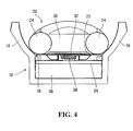
- Figure 4 is a cross-sectional end view of the portion of the uphill flume section shown in Figure 1 with the vehicle sliding thereon;
- Figure 5 is a schematic view of an exemplary control system for the uphill flume section of Figure 1;
- Figure 6 is a perspective view of a bowl of a second embodiment of the present invention;
- Figure 7 is a perspective partial cut-away view of a funnel of a third embodiment of the present invention;
- Figure 8 is a perspective view of an uphill flume section of a fourth embodiment of the present invention;
- Figure 9 is a cross-sectional end view of a fifth embodiment of the present invention; and
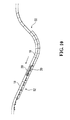
- Figure 10 is a side view of a flume ride feature in accordance with a method of the present invention.
- The present invention is directed to amusement rides in which participants ride in vehicles which slide on a sliding surface. As the term is used in the amusement ride industry, "sliding" refers to the action of moving substantially smoothly along a weight-bearing sliding surface while remaining substantially in contact with it. This is in contrast to "rolling" which refers to the action of moving along a weight bearing surface by the relative rotation of wheels, rollers, bearings, etc..
- In a waterslide context, sliding is typically facilitated by the use of water as a lubricant between the vehicle and the sliding surface. In such cases, on occasion, such as when the layer of water has sufficient depth and the vehicle has sufficient speed or lubrication, direct contact between the vehicle and the flume may be lost very briefly and temporarily with the vehicle skimming atop a very thin layer of water. However, such temporary skimming is still considered to fall within the meaning of sliding in the waterslide context.
- Embodiments will now be described.
- Flume-style waterslides typically comprise a channel or "flume" supplied with water and which accommodates a vehicle for sliding therein. The flume typically has hills and valleys as well as turns to increase the excitement of the ride for the participant. While the amusement ride described below is a flume-style waterslide, it is to be understood that in a broad sense, the invention relates to amusement rides generally.
- Figure 1 shows an exemplary uphill section of such a
flume 10 in accordance with a first embodiment of the invention, in which the vehicle would normally move from the right to the left. In operation the illustrated section is connected at itsentry 12 andexit 14 ends to other sections of the flume ride so as to provide a continuous flume from start to finish of the ride. The illustrated section would also normally be supported underneath by appropriate framing (not shown), or by a sloped section of land (not shown). In this figure, asliding surface 16 of the flume has been removed, such that elements located beneath thissliding surface 16 can be seen. - As also seen in Figures 2-4, the
flume 10 itself is generally comprised of the above-mentioned sliding surface 16 (removed in Figure 1 to illustrates components therebeneath), as well as two side walls 18 (removed in Figure 2 to show the vehicle 20). Thesliding surface 16 is the surface on which thevehicle 20 slides, while theside walls 18 assist in ensuring that thevehicle 20 remains in theflume 10. The slidingsurface 16 andside walls 18 may be made of any material providing sufficient toughness and rigidity, and may be smooth so as to permit easy sliding of thevehicle 20 thereon. In this embodiment, the slidingsurface 16 andside walls 18 are made of fiberglass, and in particular a combination of neo-isothalic gelcoat, chop strand E-Glass or S-Glass fiber, woven roving and isothalic and orthothalic resins. - In this embodiment, the
vehicle 20 is a raft adapted to carry one or more riders thereon and is provided at its bottom with avehicle bottom surface 22 adapted to slide along the slidingsurface 16 of theflume 10 during normal operation. Thevehicle 20 in this embodiment hasside tubes 24, thwarts 26 and handles 28. - Means are provided to impart a thrusting force to the
vehicle 20 to assist it up the illustrated uphill section of theflume 10. Such a force is desirable for example where the speed of thevehicle 20 arriving at theentry end 12 of the illustrated section from other parts of the flume ride is not sufficient to propel thevehicle 20 to theexit end 14 of the illustrated section at a desired speed, on the basis of the vehicle's momentum alone. To provide the external force necessary to achieve the desired speed at theexit end 14 of the illustratedflume section 10, the illustratedflume section 10 has been provided with a linear motor. - There exist many types of linear motors, including linear induction motors (LIMs) and linear synchronous motors, suitable for the present application. The exemplary linear motor used in the illustrated embodiment is a squirrel cage style linear induction motor.
- Conceptually, the linear induction motor of this embodiment is a standard rotary squirrel cage motor which has been opened out flat with the stator units lying in a spaced linear configuration and the rotor being replaced by a substantially flat reaction plate. In other embodiments, the rotor may be replaced by other elements, a curved reaction plate, an electromagnet, or a permanent magnet, for example. The units of the stator, known as linear induction motor units ("LIM units") when laid out flat, each comprise a 3 phase winding around a laminated iron core. When the LIM units are energized by an alternating current (AC) supply, a travelling wave magnetic field is produced. While a rotary motor effects rotary movement in a rotor, the flat stator of the linear induction motor effects linear movement in the reaction plate.
- The reaction component or plate in such LIMs is typically a sheet of any electrically conductive metal, for example aluminum or copper. The conducting sheet may be backed by steel to provide return paths for the stator's magnetic flux. Currents induced in the reaction plate by the LIM units' travelling field create a secondary magnetic field. It is the reaction between these two magnetic fields which imparts the linear thrust to the reaction plate. The magnitude of the thrust imparted to the reaction plate is controlled largely by the voltage and frequency of the electrical supply to the LIM units (as supplied by an inverter, not shown) and the dimensions and materials of the reaction plate. Thrust of the LIM can be reversed if the polarity is changed on the LIM units.
- In the context of a waterslide amusement ride, a LIM can control various aspects of the motion of a vehicle to which the reaction plate is affixed, depending on the configuration of the LIM units and the shape of the reaction plate. For example, the LIM can accelerate or decelerate the vehicle. It can also maintain the speed of the vehicle as it proceeds up an incline, or cause it to turn around corners. If the reaction plate is circular, it can also cause the vehicle to rotate.
- In the exemplary embodiment shown in the Figures 1 to 4, the
LIM units 30 are located under the slidingsurface 16 of theflume 10 in spaced linear relationship in the direction of travel of theride vehicle 20, and thereaction plate 32 is mounted at the bottom of thevehicle 20. - As shown in Figures 1 to 4, each
LIM unit 30 of this embodiment is rectangular in shape and is substantially flat. In this embodiment, the dimensions of each LIM unit are 500mm in length, 250mm in width, and 85mm in height and provides a thrust of 600N at 480V, 60Hz AC current and 20% duty cycle. Of course other dimensions, other voltages, other frequencies and other duty cycles may be used to provide a required thrust. - The
LIM units 30 are mounted longitudinally to aflume frame 34 such that they are located just beneath the slidingsurface 16 and substantially centered between theside walls 18. An upper surface of theLIM units 30 may alternatively form part of, or the entirety of the slidingsurface 16. In either case, the functioning portions of theLIM units 30 are located beneath the slidingsurface 16. In order to reduce cost, eachLIM unit 30 is spaced fromadjacent LIM units 30. In this embodiment, theLIM units 30 are spaced 571.5mm apart. TheLIM units 30 are electrically connected to a controlledpower supply 36. - The
reaction plate 32 is substantially flat and oblong in this embodiment. In other embodiments, other shapes ofreaction plate 32 may be used, elliptical, round or square for example. In this embodiment thereaction plate 32 is a 1/8" sheet of 1050, 1100, 1200 or 5005 aluminum and a 3/32" sheet of A36 galvanized steel affixed above the sheet of aluminum. Thereaction plate 32 is 72" in length and 18" in width, with the width of the steel sheet being 2" narrower than the aluminum sheet such that the aluminum sheet extends beyond the width of the steel sheet by 2" on each side. Examples of suitable reaction plates are detailed in a co-owned application entitled "Reaction Component for a Linear Induction Motor", filed concurrently with the present application and incorporated herein by reference in its entirety. - The
reaction plate 32 is affixed at the bottom of thevehicle 20 and may be covered by thevehicle bottom surface 22 so as to provide a smooth interface between thevehicle bottom surface 22 and theflume sliding surface 16. The distance between thereaction plate 32 and theLIM units 30 may be minimized to increase the force imparted on thevehicle 20 by theLIM units 30. In this embodiment, thebottom surface 22 of the vehicle is made of vinyl rubber, and the gap between thereaction plate 32 and theLIM units 30 is about 3/8" - 5/8" during operation. Other materials may be used for thevehicle bottom surface 22, fiberglass for example. Thevehicle 20 may be loaded with a substantially even distribution of weight or with somewhat greater weight toward the rear of thevehicle 20 so as to try to maintain proximity between thevehicle bottom surface 22 and the slidingsurface 16. - As shown in Figure 1, the
flume 10 is provided with support structures such that the slidingsurface 16 is supported by theflume frame 34. Aconduit 38 is provided below the slidingsurface 16 to accommodate electrical wires (not shown) and to allow water seeping between the slidingsurface 16 and theside walls 18 to flow downhill. All electrical elements are sealed and are double ground faulted to ensure safety. - The
flume 10 in this embodiment is also provided withproximity sensors 40 upstream of the illustrated section, and also throughout the illustrated section such that the voltage and/or frequency of the electrical supply to theLIM units 30 can be varied as a function of the speed of the vehicle to ensure that the vehicle arrives at the exit end 14 of the illustrated section at the desired speed. Such proximity sensors may be, for example, inductive proximity detectors. One model of proximity sensor which may be used is Turck Weld Field Immune Proximity Sensor 1646631. - In operation, the illustrated
flume section 10 is provided with water using any of a number of known means, for example recessed water jets located in the side walls, water flowing from a higher point in the flume, etc. The water provides lubrication between thebottom surface 22 of the vehicle and the slidingsurface 16 of theflume 10 so as to facilitate movement of thevehicle 20 up the section. In this embodiment, the water layer on the slidingsurface 16 is 1-3 mm in depth, though it is to be understood that other depths of water may be used. - At the start of the ride, the
vehicle 20 is launched from a launching station (not shown) of the flume and proceeds along the flume. As shown in Figure 5, the LIM is controlled by a drive controller. In particular, as thevehicle 20 approaches the illustrated section, theproximity sensors 40 mounted upstream of the illustrated section measure the speed of thevehicle 20 between each of these proximity sensors. This information is communicated to aprocessor 42 which calculates, based on the measured speed, a voltage and frequency to be supplied to theLIM units 30 which would likely exert sufficient force to ensure that thevehicle 20 arrives at the exit end 14 of the illustratedflume section 10 at the desired speed. In order to improve the accuracy of this calculation, vehicle weight detectors (not shown) may also be utilized, possibly at the beginning of the ride. The processor then causes thepower supply 36 to supply this voltage and frequency to theLIM units 30. - As the
vehicle 20 mounts the illustratedflume section 10, the magnetic field generated by theLIM units 30 provides a linear thrust to thereaction plate 32 affixed to the bottom of thevehicle 20, causing thevehicle 20 to maintain its speed, or accelerate up the illustratedsection 10. As thevehicle 20 proceeds up the illustratedsection 10, theother proximity sensors 40 monitor the speed of thevehicle 20 and the power supply to theLIM units 30 is adjusted accordingly. In this embodiment, theLIM units 30 are powered successively to provide thrust to thevehicle 20 when thevehicle 20 is over thepowered LIM units 30. - While the
proximity sensors 40 discussed above detect a position of thevehicle 20, other sensors could be used to measure one or more of position, linear speed, rotational speed, and direction of movement of thevehicle 20, and cause theLIM units 30 to operate so as to affect motion of thevehicle 20 in a desired manner, for example by decelerating thevehicle 20, slowing its rotation, or changing its direction of motion. - As described, the illustrated embodiment reduces the need for a direct contact outside force on the
vehicle 20 to assist it up the incline, a feature which improves the safety of the ride while also increasing its rider comfort and aesthetic appeal. - While this embodiment has been described as an amusement ride feature, it is to be understood that the present invention also contemplates an amusement ride embodying such an amusement ride feature, a method of using a LIM to affect motion of a vehicle in an amusement ride, a ride vehicle having a reaction plate for use on a LIM-enabled ride, and a LIM-enabled sliding surface having LIM units mounted therebeneath.
- While this embodiment ride has been described as being a waterslide ride, it is to be understood that the present invention can be applied in non-water sliding amusement rides, including so-called dry rides. One example would be a ride in which a vehicle slides on a sliding surface having a low-friction coating such as TEFLON™.
- Further, although this embodiment has been described in detail in the context of a flume ride, it is to be understood that the present invention may also be applied to other types of sliding amusement rides. For example, Figure 6 is an illustration of a bowl-style ride or ride feature in which
LIM units 30 are embedded around the bowl so as to maintain a ride vehicle's motion around the bowl before it is released and allowed to corkscrew towards the middle. Such a bowl-style ride is described in U.S. Design PatentNo. D521,098, issued May 16, 2006 , incorporated herein in its entirety. Figure 7 illustrates a funnel-style ride or ride feature in whichLIM units 30 are embedded along the sides so as to increase or decrease the amplitude with which the ride vehicle oscillates along the funnel. This funnel-style ride is a completed funnel turned on its side and in Figure 7, an upper side portion of the funnel has been cut away for the sole purpose of showing interior features. Such a funnel ride is described inU.S. Patent No. 6,857,964 issued February 22, 2005 ,U.S. Patent No. 7,056,220 issued June 6, 2006 , and in co-pendingU.S. Application Serial No. 11/381,557 filed May 4, 2006 - While this embodiment has been described as being an uphill section in the middle of a ride, it will be understood that the present invention can be applied in other sections of an amusement ride. For example, the
LIM units 30 may be embedded in a horizontal section at the launch station to accelerate theride vehicle 20 and launch it into the ride. Alternatively,LIM units 30 may be embedded in an uphill section near the launch station so as to either take aride vehicle 20 containing a rider to the top of a first hill, or to return anempty vehicle 20 to an elevated launch station. Further,LIM units 30 may be embedded at the end of a ride so as to slow down thevehicle 20 as it approaches the end of the ride, or the launch station. IndeedLIM units 30 may be embedded in downhill sections to control the rate of descent of theride vehicle 20. - Other modifications are possible. For example, instead of the
ride vehicle 20 having only onereaction plate 32, it may havemultiple reaction plates 32. Further, as illustrated in Figure 9, instead of theLIM units 30 being mounted beneath the slidingsurface 16 of theflume 10 and thereaction plate 32 being mounted at the bottom of theride vehicle 20, theLIM units 30 may be mounted outside of and parallel to theside walls 18 of theflume 10 and thereaction plates 32 may be mounted to theride vehicle 20 such that they are parallel to theside walls 18 of the flume when theride vehicle 20 is in theflume 10. - It is to be understood that while the LIM in the illustrated embodiment is used to maintain the speed of, or to accelerate the
ride vehicle 20, the LIM can also be used to impart other motion control to thevehicle 20. For example, the LIM can be used to decelerate theride vehicle 20, resist acceleration of theride vehicle 20 down a slope, or indeed to stop it or reverse its direction. Further, inother LIM unit 30 andreaction plate 32 configurations, the LIM can be used to cause theride vehicle 20 to rotate. For example the linear motor force could be arranged off center so that a turning moment is created in thereaction plate 32. Alternatively,adjacent LIM units 30 could thrust in opposite directions to create the turning moment. Additionally, the selective operation of multiple LIM unit sets in angular relationship to each other can cause theride vehicle 20 to selectively follow different trajectories. The LIM can also be used to cause or assist theride vehicle 20 in going around corners. Of course, a combination of these motions can also be implemented, for example a LIM which causes theride vehicle 20 to rotate as it decelerates, or a LIM which causes theride vehicle 20 to accelerate as it goes around a corner, as shown in Figure 8. - Alternatively, as illustrated in Figure 10, the LIM can be used to provide other ride motion. For example, in a ride feature comprising a
downhill section 50 followed by anuphill section 52, as thevehicle 20 proceeds down thedownhill section 50 and up theuphill section 52, the LIM may be operated such that thevehicle 20 reaches a certain height. The LIM may then be deactivated, causing thevehicle 20 to slide backwards down theuphill section 52 and up thedownhill section 50. Thevehicle 20 will then slide back down thedownhill section 50 and up theuphill section 52 whereupon the LIM may be reactivated such that thevehicle 20 reaches the top of theuphill section 52 at a desired speed. - While the
vehicle 20 in the illustrated embodiments has been illustrated as a flat-bottomed raft, it is to be understood that thevehicle 20 in accordance with the present invention can be any vehicle adapted to convey at least one rider in a sliding amusement ride, for example an inner-tube-style vehicle, a multi-rider vehicle, or a platform vehicle. - While the linear induction motor drive has been described in the illustrated embodiments as comprising linear
induction motor units 30 embedded below the slidingsurface 16 and thereaction plate 32 mounted at the bottom of theride vehicle 20, it is to be understood that other suitable configurations are possible. For example, the linearinduction motor units 30 may be mounted at the bottom of theride vehicle 20 as powered by batteries and controlled remotely, withmultiple reaction plates 32 mounted beneath the surface of theride surface 16. - While the
flume 10, theLIM units 30, thereaction plate 32, and other features have been described in some cases as having particular dimensions and being made of particular materials, it will be understood by persons skilled in the art that other dimensions and materials may be used without necessarily departing from the scope of the present invention. - Further, while the linear motor of the illustrated embodiments has been described as being a linear induction motor, it is to be understood that other types of linear motors may be used, linear synchronous motors, for example.
- Finally, specific details of the particular LIM utilized in the illustrated embodiments of the invention have been provided in some cases. However, persons skilled in the art will understand that other types of LIMs having different configurations, specifications, and dimensions can be utilized without necessarily departing from the scope of the present invention.
- Numerous modifications and variations of the present invention are possible in light of the above teachings. It is therefore to be understood that within the scope of the appended claims, the invention may be practised otherwise than as specifically described herein.
Claims (26)
- An amusement ride feature comprising:a sliding surface;a vehicle adapted to slide on said sliding surface and to convey at least one rider thereon; anda linear motor associated with the vehicle and the sliding surface for affecting sliding motion of the vehicle on the sliding surface.
- The amusement ride feature of claim 1 wherein the linear motor is a linear induction motor.
- The amusement ride feature of either one of claims 1 and 2 wherein said linear motor comprises at least one reaction plate mounted to said vehicle,
which at least one reaction plate is optionally mounted near a bottom of said vehicle and substantially parallel thereto, and
which at least one reaction plate is optionally covered by a vehicle bottom surface which slides on the sliding surface. - The amusement ride feature of any one of claims 1 to 3 wherein said linear motor further comprises a plurality of linear induction motor units located beneath the sliding surface.
- The amusement ride feature of any one of claims 1 to 4 further comprising sensors for detecting a vehicle parameter of the vehicle, said vehicle parameter comprising at least one of a linear speed, a rotational speed, a direction of movement, a weight and a position of the vehicle, and a controller for operating the linear motor as a function of the detected vehicle parameter of the vehicle.
- The amusement ride feature of claim 1 wherein the linear motor is a linear synchronous motor.
- The amusement ride feature of any of claims 1, 2 or 6 wherein the sliding surface is a waterslide sliding surface.
- The amusement ride feature of any one of claims 1 to 7 wherein the linear motor is adapted to achieve at least one of:a) to maintain a speed of the vehicle on the sliding surface;b) to accelerate the vehicle on the sliding surface;.c) to decelerate the vehicle on the sliding surface;d) to control a rotational speed of the vehicle on the sliding surface;e) to change a direction of movement of the vehicle on the sliding surface.
- The amusement ride feature of any one of claims 1 to 8 wherein the ride feature is flume-style, the sliding surface is a bottom surface of a water flume, and said vehicle is adapted to convey said at least one rider along said water flume.
- An amusement ride which includes the amusement ride feature of any one of claims 1 to 9.
- A method of controlling the sliding motion of a vehicle sliding on a sliding surface in an amusement ride, comprising operating a linear motor associated with the vehicle and the sliding surface.
- The method of claim 11 wherein the linear motor is a linear induction motor or a linear synchronous motor.
- The method of either one of claims 11 and 12 wherein the linear motor comprises a plurality of linear induction motor units located beneath the sliding surface, and at least one reaction plate mounted near a bottom of said vehicle and substantially parallel thereto, said at least one reaction plate covered by a vehicle bottom surface which slides on the sliding surface, and said operating of said linear motor comprises energizing the linear induction motor units to create a magnetic field which imparts a lateral force on the reaction plate.
- The method of any one of claims 11 to 13 wherein the ride feature is flume-style, the sliding surface is a bottom surface of a water flume, and said vehicle conveys said at least one rider along said water flume.
- A method of controlling the sliding motion of a vehicle sliding on a sliding surface in an amusement ride, comprising:providing the sliding surface;placing the vehicle on the sliding surface; andoperating a linear motor associated with the vehicle and the sliding surface.
- The method of claim 15 wherein the linear motor is a linear induction motor.
- The method of any one of claims 11 to 16 wherein the sliding surface is a waterslide sliding surface.
- The method of any one of claims 15 to 17 wherein said linear motor comprises at least one reaction plate mounted to said vehicle,
which at least one reaction plate is optionally mounted near a bottom of said vehicle and substantially parallel thereto, and
optionally wherein said at least one reaction plate is covered by a vehicle bottom surface which slides on the sliding surface. - The method of any one of claims 15 to 18 wherein said linear motor further comprises a plurality of linear induction motor units located beneath the sliding surface, and said operating of said linear motor comprises energizing the linear induction motor units to create a magnetic field which imparts a lateral force on the reaction plate.
- The method of any one of claims 15 to 19 further comprising:providing sensors for detecting a vehicle parameter of the vehicle, said vehicle parameter comprising at least one of a linear speed, a rotational speed, a direction of movement, a weight and a position of the vehicle;providing a controller for operating the linear motor; andoperating the controller to operate the linear motor as a function of the detected vehicle parameter of the vehicle.
- The method of claim 15 wherein the linear motor is a linear synchronous motor.
- The method of any one of claims 15 to 21 wherein the linear motor is operated to achieve at least one of the following:a) to maintain a speed of the vehicle on the sliding surface;b) to accelerate the vehicle on the sliding surface;c) to decelerate the vehicle on the sliding surface;d) to control a rotational speed of the vehicle on the sliding surface;e) to change a direction of movement of the vehicle on the sliding surface.
- The method of any one of claims 15 to 22 wherein the amusement ride is flume-style, the sliding surface is a bottom surface of a water flume, and said vehicle is adapted to convey said at least one rider along said water flume.
- An amusement ride sliding surface for bearing a vehicle in sliding relationship thereto, said vehicle conveying at least one rider and having affixed thereto at least one reaction component, said sliding surface having located therebeneath, a plurality of linear induction motor units for interacting with the at least one reaction component affixed to the vehicle to affect sliding motion of the vehicle on the sliding surface,
which sliding surface is optionally a bottom surface of a waterslide flume. - An amusement ride vehicle adapted to slide on an amusement ride sliding surface and to convey at least one rider thereon, said vehicle having affixed thereto at least one reaction plate for interacting with linear induction motor units associated with the sliding surface to affect sliding motion of the vehicle on the sliding surface,
which at least one reaction plate is optionally mounted near a bottom of said vehicle and substantially parallel thereto and
optionally wherein said at least one reaction plate is covered by a vehicle bottom surface which slides on the sliding surface, for example wherein the ride vehicle is a waterslide vehicle, and the sliding surface is a bottom surface of a flume. - The amusement ride feature of any one of claims 1, 2 and 7 wherein the linear motor comprises a plurality of linear induction motor units located beneath the sliding surface, and at least one electromagnet or permanent magnet mounted near a bottom of said vehicle.
Priority Applications (5)
| Application Number | Priority Date | Filing Date | Title |
|---|---|---|---|
| EP10181293.1A EP2335792B1 (en) | 2006-03-03 | 2007-03-02 | Linear motor driven amusement ride and method of controlling |
| DK10181293.1T DK2335792T3 (en) | 2006-03-03 | 2007-03-02 | Linear motor driven amusement and control method |
| PL07250876T PL1829592T3 (en) | 2006-03-03 | 2007-03-02 | Linear motor driven amusement ride and method |
| PL10181293T PL2335792T3 (en) | 2006-03-03 | 2007-03-02 | Linear motor driven amusement ride and method of controlling |
| CY20121101188T CY1113455T1 (en) | 2006-03-03 | 2012-12-05 | ENTERTAINMENT PARK GAME ROUTE AND METHOD FROM A LINE ENGINE |
Applications Claiming Priority (1)
| Application Number | Priority Date | Filing Date | Title |
|---|---|---|---|
| US77838406P | 2006-03-03 | 2006-03-03 |
Related Child Applications (2)
| Application Number | Title | Priority Date | Filing Date |
|---|---|---|---|
| EP10181293.1A Division-Into EP2335792B1 (en) | 2006-03-03 | 2007-03-02 | Linear motor driven amusement ride and method of controlling |
| EP10181293.1A Division EP2335792B1 (en) | 2006-03-03 | 2007-03-02 | Linear motor driven amusement ride and method of controlling |
Publications (2)
| Publication Number | Publication Date |
|---|---|
| EP1829592A1 true EP1829592A1 (en) | 2007-09-05 |
| EP1829592B1 EP1829592B1 (en) | 2012-09-19 |
Family
ID=38039182
Family Applications (2)
| Application Number | Title | Priority Date | Filing Date |
|---|---|---|---|
| EP10181293.1A Active EP2335792B1 (en) | 2006-03-03 | 2007-03-02 | Linear motor driven amusement ride and method of controlling |
| EP07250876A Active EP1829592B1 (en) | 2006-03-03 | 2007-03-02 | Linear motor driven amusement ride and method |
Family Applications Before (1)
| Application Number | Title | Priority Date | Filing Date |
|---|---|---|---|
| EP10181293.1A Active EP2335792B1 (en) | 2006-03-03 | 2007-03-02 | Linear motor driven amusement ride and method of controlling |
Country Status (9)
| Country | Link |
|---|---|
| US (11) | US8136453B2 (en) |
| EP (2) | EP2335792B1 (en) |
| KR (2) | KR101318739B1 (en) |
| CN (2) | CN101394908B (en) |
| CA (1) | CA2580220C (en) |
| DK (2) | DK1829592T3 (en) |
| ES (2) | ES2481048T3 (en) |
| PL (2) | PL1829592T3 (en) |
| WO (3) | WO2007098600A1 (en) |
Cited By (4)
| Publication number | Priority date | Publication date | Assignee | Title |
|---|---|---|---|---|
| WO2009061653A2 (en) | 2007-11-05 | 2009-05-14 | Disney Enterprises, Inc. | Magnetic pacer for controlling speeds in amusement park rides |
| WO2011119120A1 (en) * | 2010-03-23 | 2011-09-29 | Poli̇n Su Parklari Ve Havuz Si̇stemleri̇ Anoni̇m Şi̇rketi̇ | Multilane waterslide with a common sliding area |
| EP3177479A1 (en) * | 2014-08-05 | 2017-06-14 | Universal City Studios LLC | Systems and methods for braking or launching a ride vehicle |
| WO2018044704A1 (en) * | 2016-08-29 | 2018-03-08 | Universal City Studios Llc | Systems and methods for braking or propelling a roaming vehicle |
Families Citing this family (39)
| Publication number | Priority date | Publication date | Assignee | Title |
|---|---|---|---|---|
| DE102004062315A1 (en) * | 2004-12-20 | 2006-06-29 | Mack Ride Gmbh & Co Kg | Water ride |
| EP2335792B1 (en) | 2006-03-03 | 2014-04-23 | HM Attractions, Inc. | Linear motor driven amusement ride and method of controlling |
| DE102007052823A1 (en) * | 2007-02-22 | 2008-08-28 | Maurer Söhne Gmbh & Co. Kg | Rideship and method of operating a ride |
| US20090017927A1 (en) * | 2007-07-11 | 2009-01-15 | Paul Takeshi Shozi | Amusement Ride With Mechanical Lift, Slides, Sequenced Ejections, And Show Systems |
| US7950333B2 (en) * | 2008-03-11 | 2011-05-31 | Disney Enterprises, Inc. | Passive magnetic levitation ride for amusement parks |
| CN101980757B (en) | 2008-03-26 | 2014-03-26 | 维科马乘骑工程公司 | Amusement device and propelling method for propelling a passenger carrier of such amusement device |
| JP2010284828A (en) * | 2009-06-09 | 2010-12-24 | Ihi Corp | Offset printer |
| US8070616B2 (en) * | 2009-07-31 | 2011-12-06 | Raymond Joseph Dubois | Method and apparatus for adjusting rider movement on a waterslide amusement device |
| WO2012012568A2 (en) * | 2010-07-21 | 2012-01-26 | Whitewater West Industries Ltd. | Method and system for expandable modular raft and a water ride using the same |
| US8091483B1 (en) * | 2011-03-31 | 2012-01-10 | Disney Enterprises, Inc. | Amusement park ride with underwater-controlled boats |
| CA2840255C (en) * | 2011-06-30 | 2018-03-20 | Hm Attractions Inc. | Motion control system and method for an amusement ride |
| DE102012104687B3 (en) * | 2012-05-30 | 2013-09-19 | Maurer Söhne Gmbh & Co. Kg | Section for a ride, procedure for the passage of a section of the route and rides |
| IN2015DN04194A (en) * | 2012-10-19 | 2015-10-16 | Proslide Technology Inc | |
| WO2014121395A1 (en) * | 2013-02-06 | 2014-08-14 | Skyturtle Technologies Ltd. | Friction reducing waterslide section |
| RU2525796C1 (en) * | 2013-04-30 | 2014-08-20 | Федеральное государственное бюджетное образовательное учреждение высшего профессионального образования "Петербургский государственный университет путей сообщения" | Gangway shoot with magnetic levitation carrier |
| US9844732B2 (en) * | 2013-05-21 | 2017-12-19 | Skyturtle Technologies Ltd. | Water slide having axialy rotatable waterslide vehicle |
| MY176739A (en) | 2013-10-02 | 2020-08-20 | Velocity Magnetic Inc | Solid state energy storage and management system |
| US9597603B1 (en) | 2014-12-03 | 2017-03-21 | Skyturtle Technologies Ltd | Linear induction motor use with waterslide raft on non riding surfaces |
| DE102014119352A1 (en) * | 2014-12-22 | 2016-06-23 | Weber Maschinenbau Gmbh Breidenbach | MOTION DEVICE WITH OPERATING AND MAINTENANCE CONFIGURATION |
| CN104436701B (en) * | 2014-12-23 | 2016-09-07 | 郑运婷 | The motor-driven game machine of space |
| CN104436700B (en) * | 2014-12-23 | 2016-08-31 | 青岛橡胶谷知识产权有限公司 | Game device |
| CN106139596A (en) * | 2015-04-02 | 2016-11-23 | 江苏金刚文化科技集团股份有限公司 | The walking mechanism of roller-coaster |
| CN105169706A (en) * | 2015-09-28 | 2015-12-23 | 万达文化旅游规划研究院有限公司 | Mega drop entertainment machine driven by linear motor |
| US20200279682A1 (en) * | 2016-01-04 | 2020-09-03 | Renjith THOMAS | Magnetic levitation mounted and controlled payload on a curved surface |
| CA3038801A1 (en) * | 2016-03-30 | 2017-10-05 | Nicholas G. Suttell | Versatile translational and rotational motion simulator |
| EP3436913B1 (en) * | 2016-03-30 | 2021-11-24 | Suttell, Nicholas, G. | Versatile translational and rotational motion simulator |
| RU2634887C1 (en) * | 2016-06-28 | 2017-11-07 | Александр Поликарпович Лялин | "running wave" ride |
| US10843091B1 (en) | 2016-11-02 | 2020-11-24 | Brandon Paul | Amusement park attractions, amusement karts, and magnetic assemblies |
| FR3063983A1 (en) * | 2017-03-17 | 2018-09-21 | C.E.R.M.E.X. Constructions Etudes Et Recherches De Materiels Pour L'emballage D'expedition | DEVICE FOR TRANSFERRING OBJECTS |
| AT519829A1 (en) * | 2017-04-04 | 2018-10-15 | B & R Ind Automation Gmbh | Method for operating a long-stator linear motor |
| JP7161524B2 (en) | 2017-09-13 | 2022-10-26 | レイトラム,エル.エル.シー. | Monorail tray conveyor with passive guide rails |
| US10654660B2 (en) * | 2018-01-31 | 2020-05-19 | Laitram, L.L.C. | Hygienic magnetic tray and conveyor |
| US10807803B2 (en) | 2018-01-31 | 2020-10-20 | Laitram, L.L.C. | Hygienic low-friction magnetic tray and conveyor |
| CN108686379A (en) * | 2018-07-09 | 2018-10-23 | 胡泓宇 | A kind of water slide electromagnetism acceleration system |
| US11058959B2 (en) * | 2019-03-14 | 2021-07-13 | Universal City Studios Llc | Vertical motion drive system for a ride system |
| CA187680S (en) * | 2019-05-24 | 2021-05-04 | Proslide Technology Inc | Water ride structure |
| WO2022193013A1 (en) * | 2021-03-18 | 2022-09-22 | Proslide Technology Inc. | Anti-reversal system for water slides |
| CN113904520B (en) * | 2021-09-26 | 2023-03-24 | 深圳大学 | Low-energy-consumption linear motor special for hydrogen fuel cell |
| CN117318432B (en) * | 2023-11-29 | 2024-02-20 | 湖南天友精密技术有限公司 | Dynamic magnetic type permanent magnet motor and control method |
Citations (4)
| Publication number | Priority date | Publication date | Assignee | Title |
|---|---|---|---|---|
| WO1998031444A1 (en) * | 1997-01-16 | 1998-07-23 | Fiske Orlo J | Amusement vehicle |
| US6397755B1 (en) * | 2000-09-11 | 2002-06-04 | Ride Factory Incorporated | Amusement ride |
| WO2004085744A1 (en) * | 2003-03-25 | 2004-10-07 | Thyssenkrupp Transrapid Gmbh | Carrier and a magnetic levitation railway provided with said deck |
| US20050098057A1 (en) * | 1996-06-11 | 2005-05-12 | Mckoy Errol W. | Watercraft amusement ride |
Family Cites Families (83)
| Publication number | Priority date | Publication date | Assignee | Title |
|---|---|---|---|---|
| US3617A (en) * | 1844-06-05 | Smut-machine | ||
| US233906A (en) * | 1880-11-02 | Combined stirrer and thermometer | ||
| US1307833A (en) * | 1919-06-24 | Electbic switch | ||
| US2473804A (en) * | 1947-06-05 | 1949-06-21 | Arthur T Ledoux | Draft control for oil burners |
| US3404635A (en) * | 1965-04-16 | 1968-10-08 | Walt Disney Prod | Boat amusement ride |
| US4175637A (en) | 1967-04-21 | 1979-11-27 | Bertelsen William R | Surface effect vehicles and guideways therefor |
| FR1574831A (en) | 1968-05-06 | 1969-07-18 | ||
| BR6912626D0 (en) | 1968-09-26 | 1973-04-12 | Tracked Avercraft Ltd | LINEAR INDUCTION MOTOR FOR VEHICLE PROPULSION |
| GB1307833A (en) | 1969-06-18 | 1973-02-21 | Tracked Hovercraft Ltd | Linear induction motor primary member |
| GB1316131A (en) | 1969-09-18 | 1973-05-09 | Tracked Hovercraft Ltd | Linear induction motor |
| US3696753A (en) | 1969-10-29 | 1972-10-10 | Transportation Technology | Guideway and switching linear motor propelled vehicle |
| DE2021834C3 (en) | 1970-05-05 | 1974-05-09 | Messerschmitt-Boelkow-Blohm Gmbh, 8000 Muenchen | Magnetic levitation train |
| US3667398A (en) * | 1970-06-26 | 1972-06-06 | Tracked Hovercraft Ltd | Linear induction motor secondary member |
| US3680488A (en) | 1970-09-16 | 1972-08-01 | Transportation Technology | Transportation system having inertial switch system |
| US3712240A (en) * | 1971-02-23 | 1973-01-23 | Transportation Technology | Linear electric motor propulsion system |
| US3738281A (en) | 1971-05-06 | 1973-06-12 | Rohr Industries Inc | Emergency support and decelerating mechanism for magnetically supported vehicle |
| US3667397A (en) * | 1971-06-25 | 1972-06-06 | Tracked Hovercraft Ltd | Linear induction motor secondary member |
| GB1435750A (en) | 1972-07-17 | 1976-05-12 | Krauss Maffei Ag | Trackway for a transport system |
| US3830161A (en) | 1973-07-06 | 1974-08-20 | Arrow Dev Co | Flume boat ride with a double downchute |
| CA1002565A (en) * | 1973-11-15 | 1976-12-28 | Herbert E. Gladish | Vehicular transportation system |
| US3947741A (en) | 1974-01-15 | 1976-03-30 | Walt Disney Productions | Boat guidance system |
| US3889605A (en) | 1974-02-19 | 1975-06-17 | Arrow Dev Co | Amusement ride with a vehicle track portion following the shape of a helix |
| JPS50122627A (en) | 1974-03-16 | 1975-09-26 | ||
| US4001514A (en) * | 1974-12-09 | 1977-01-04 | Itt Canada, Limited | Subscriber digital multiplexing system with time division concentration |
| US4061089A (en) | 1975-09-02 | 1977-12-06 | Elbert Morgan Sawyer | Personal rapid transit system |
| US4063517A (en) | 1975-10-17 | 1977-12-20 | Nardozzi Jr Michael A | Rapid transit system |
| JPS5918923B2 (en) | 1976-06-09 | 1984-05-01 | 株式会社東芝 | Magnetic levitation propulsion device |
| DE2705954C3 (en) | 1977-02-12 | 1981-06-11 | Krauss-Maffei AG, 8000 München | Rail joint connection for an asynchronous linear motor |
| JPS5435914A (en) | 1977-08-22 | 1979-03-16 | Akebono Brake Ind Co Ltd | Hydro-railway device propelled by means of linear motor |
| DE2824951A1 (en) * | 1978-06-07 | 1979-12-20 | Kabel Metallwerke Ghh | METHOD OF MANUFACTURING A STATOR FOR A LINEAR MOTOR |
| DE2842099C3 (en) * | 1978-09-27 | 1981-07-23 | Siemens AG, 1000 Berlin und 8000 München | Synchronous linear stator motor |
| DE2900053A1 (en) | 1979-01-02 | 1980-07-10 | Thyssen Industrie | High speed track magnetic rail joints - have spacers and clamps, elastomer fillings, and fish plate with slots allowing movement |
| US4299171A (en) * | 1979-12-26 | 1981-11-10 | Arrow Huss Inc. | Demountable flume amusement ride |
| US4484739A (en) | 1983-03-15 | 1984-11-27 | Wavetek International, Inc. | Plastic slide for sleds |
| DE3902949A1 (en) | 1989-02-01 | 1990-08-09 | Thyssen Industrie | VEHICLE CARRIERS FOR MAGNETIC RAILWAYS |
| JP3072297B2 (en) | 1989-06-23 | 2000-07-31 | 欣二郎 吉田 | Propulsion method of tracked vehicle by synchronous linear motor |
| US4984783A (en) * | 1989-10-20 | 1991-01-15 | Shiratori Co. Ltd. | Water sliders with turning toboggans |
| US4991514A (en) * | 1989-12-26 | 1991-02-12 | Powell Tyrone E | Electromagnetically powered drag ride attraction |
| JPH0422384A (en) | 1990-05-17 | 1992-01-27 | Shiratori:Kk | Sliding passage for water slider |
| WO1991019621A1 (en) | 1990-06-20 | 1991-12-26 | Kabushiki Kaisha Yaskawa Denki | Underwater linear transport system |
| US5128569A (en) | 1991-04-25 | 1992-07-07 | Gladish Herbert E | Linear induction motors |
| CA2075122A1 (en) | 1991-09-23 | 1993-03-24 | He Holdings, Inc. | Multiple participant moving vehicle shooting gallery |
| JPH084660B2 (en) | 1992-04-07 | 1996-01-24 | 幹次 村上 | Experience environment device with 3D image |
| US5277125A (en) | 1992-10-28 | 1994-01-11 | Bae Automated Systems, Inc. | Material handling car and track assembly having opposed magnet linear motor drive and opposed permanent magnet brake assembly |
| US5403238A (en) * | 1993-08-19 | 1995-04-04 | The Walt Disney Company | Amusement park attraction |
| US5628253A (en) * | 1993-09-04 | 1997-05-13 | Railway Technical Research Institute | Ground-propulsion special-purpose electromagnetic circuit for magnetically levitated railway, and method of laying said circuit |
| US5433671A (en) * | 1993-12-27 | 1995-07-18 | Davis; Walter D. | Water amusement ride |
| DE4344755A1 (en) | 1993-12-28 | 1995-06-29 | Martin K Rzyttka | Electromagnetic high speed drive for rail vehicles and ships |
| US5669821A (en) | 1994-04-12 | 1997-09-23 | Prather; James G. | Video augmented amusement rides |
| US5511488A (en) | 1994-04-25 | 1996-04-30 | Powell; James R. | Electromagnetic induction ground vehicle levitation guideway |
| US5540622A (en) * | 1994-09-26 | 1996-07-30 | The Walt Disney Company | Water slide |
| US5552649A (en) * | 1994-11-08 | 1996-09-03 | Cowan, Jr.; Maynard | Segmented rail linear induction motor |
| US5668421A (en) * | 1995-04-06 | 1997-09-16 | E. B. Eddy Forest Products Ltd. | Pressurized air-gap guided active linear motor suspension system |
| JP3027703B2 (en) | 1995-06-14 | 2000-04-04 | 松下電器産業株式会社 | Active matrix liquid crystal display |
| US6243691B1 (en) * | 1996-03-29 | 2001-06-05 | Onsale, Inc. | Method and system for processing and transmitting electronic auction information |
| US5860364A (en) | 1996-06-11 | 1999-01-19 | Mckoy; Errol W. | Amusement boat ride featuring linear induction motor drive integrated with guide channel structure |
| CN2303755Y (en) * | 1997-06-10 | 1999-01-13 | 何丽凌 | Suspension train for entertainment |
| US6413165B1 (en) | 1997-11-18 | 2002-07-02 | Bill A. Crandall | Intermittenly wetted sliding amusement ride |
| US6293376B1 (en) * | 1999-11-22 | 2001-09-25 | Magnetar Technologies Ltd | Apparatus including eddy current braking system |
| US6527646B1 (en) * | 2000-01-27 | 2003-03-04 | Rick A. Briggs | Competition water slide |
| DE10011118B4 (en) | 2000-03-09 | 2008-11-27 | Thyssenkrupp Transrapid Gmbh | Linear motor for a linear drive of a maglev train |
| AU2001290826A1 (en) * | 2000-09-11 | 2002-03-26 | Nbgs International, Inc. | Water amusement conveyor system and method |
| US6743108B2 (en) | 2000-12-12 | 2004-06-01 | Proslide Technology Inc. | Random path flume ride |
| CA2328339C (en) | 2000-12-13 | 2003-06-10 | Whitewater West Industries Ltd. | Waterslide bowl |
| US20030140815A1 (en) | 2002-01-29 | 2003-07-31 | Norbury Steven A. | Real-size simulated drag strip ride |
| US20060032395A1 (en) | 2002-05-28 | 2006-02-16 | Johann Matuschek | Driveway, driveway module, and method for the production thereof |
| US7713134B2 (en) | 2002-06-18 | 2010-05-11 | Proslide Technology Inc. | Reducing radius slide feature |
| CA2432675C (en) * | 2002-06-18 | 2008-09-23 | Proslide Technology Inc. | Reducing radius slide feature |
| DE10253136A1 (en) | 2002-11-14 | 2004-05-27 | Cbp Guideway Systems Gmbh | Running rail and stator construction for magnetic overhead monorail, has stator packets with arch-shaped cutouts at bottom for stator windings, bolted into inverted U-section rail |
| US6827022B2 (en) | 2002-12-27 | 2004-12-07 | General Atomics | Magnetic levitation and propulsion system |
| US7904346B2 (en) * | 2002-12-31 | 2011-03-08 | Ebay Inc. | Method and system to adjust a seller fixed price offer |
| USD521098S1 (en) | 2003-05-09 | 2006-05-16 | Proslide Technology Inc. | Water bowl ride exit flume |
| DE102004028948A1 (en) | 2004-06-14 | 2005-12-29 | Thyssenkrupp Transrapid Gmbh | Track carrier and thus produced magnetic levitation railway |
| US7654203B2 (en) * | 2004-06-22 | 2010-02-02 | The Texas A&M University System | Freight transportation system and method |
| US7597630B2 (en) | 2004-11-24 | 2009-10-06 | Water Ride Concepts, Inc. | Water amusement park conveyors |
| DE102004062315A1 (en) | 2004-12-20 | 2006-06-29 | Mack Ride Gmbh & Co Kg | Water ride |
| US20060219124A1 (en) | 2005-03-31 | 2006-10-05 | Jordan Jeffrey T | Buoyant marine rail system |
| US7371183B2 (en) * | 2005-08-30 | 2008-05-13 | Henry, Schooley & Associates, L.L.C. | Water amusement park conveyors |
| USD548810S1 (en) * | 2006-03-02 | 2007-08-14 | Hunter Richard D | Water ride corkscrew feature |
| EP2335792B1 (en) * | 2006-03-03 | 2014-04-23 | HM Attractions, Inc. | Linear motor driven amusement ride and method of controlling |
| JP5435914B2 (en) | 2007-12-11 | 2014-03-05 | 株式会社Uacj | Method for producing aluminum alloy plate for cold press forming, method for cold press forming aluminum alloy plate, and aluminum alloy cold press formed product |
| CA2840255C (en) * | 2011-06-30 | 2018-03-20 | Hm Attractions Inc. | Motion control system and method for an amusement ride |
| CA2852868A1 (en) * | 2013-05-29 | 2014-11-29 | Whitewater West Industries Ltd. | Inflatable water attraction and ride vehicle |
-
2007
- 2007-03-02 EP EP10181293.1A patent/EP2335792B1/en active Active
- 2007-03-02 CN CN2007800077143A patent/CN101394908B/en active Active
- 2007-03-02 DK DK07250876.5T patent/DK1829592T3/en active
- 2007-03-02 CN CN201310052779.7A patent/CN103223246B/en active Active
- 2007-03-02 PL PL07250876T patent/PL1829592T3/en unknown
- 2007-03-02 CA CA2580220A patent/CA2580220C/en active Active
- 2007-03-02 US US11/681,702 patent/US8136453B2/en active Active
- 2007-03-02 EP EP07250876A patent/EP1829592B1/en active Active
- 2007-03-02 WO PCT/CA2007/000333 patent/WO2007098600A1/en active Application Filing
- 2007-03-02 ES ES10181293.1T patent/ES2481048T3/en active Active
- 2007-03-02 WO PCT/CA2007/000334 patent/WO2007098601A1/en active Application Filing
- 2007-03-02 US US11/681,691 patent/US8162770B2/en active Active
- 2007-03-02 US US11/681,712 patent/US8038542B2/en not_active Expired - Fee Related
- 2007-03-02 DK DK10181293.1T patent/DK2335792T3/en active
- 2007-03-02 KR KR1020127027756A patent/KR101318739B1/en active IP Right Grant
- 2007-03-02 ES ES07250876T patent/ES2396102T3/en active Active
- 2007-03-02 WO PCT/CA2007/000329 patent/WO2007098596A1/en active Application Filing
- 2007-03-02 US US11/681,720 patent/US7918741B2/en active Active
- 2007-03-02 PL PL10181293T patent/PL2335792T3/en unknown
-
2008
- 2008-09-22 KR KR1020087023089A patent/KR101342459B1/en active IP Right Grant
-
2011
- 2011-10-11 US US13/270,518 patent/US9061214B2/en not_active Expired - Fee Related
- 2011-12-20 US US13/331,355 patent/US8905854B2/en active Active
-
2012
- 2012-02-09 US US13/370,117 patent/US8826824B2/en active Active
-
2014
- 2014-08-18 US US14/461,547 patent/US20150190721A1/en not_active Abandoned
-
2015
- 2015-12-17 US US14/972,168 patent/US20160339348A1/en not_active Abandoned
-
2017
- 2017-09-08 US US15/699,731 patent/US20180214781A1/en not_active Abandoned
-
2019
- 2019-04-09 US US16/379,130 patent/US20200129871A1/en not_active Abandoned
Patent Citations (4)
| Publication number | Priority date | Publication date | Assignee | Title |
|---|---|---|---|---|
| US20050098057A1 (en) * | 1996-06-11 | 2005-05-12 | Mckoy Errol W. | Watercraft amusement ride |
| WO1998031444A1 (en) * | 1997-01-16 | 1998-07-23 | Fiske Orlo J | Amusement vehicle |
| US6397755B1 (en) * | 2000-09-11 | 2002-06-04 | Ride Factory Incorporated | Amusement ride |
| WO2004085744A1 (en) * | 2003-03-25 | 2004-10-07 | Thyssenkrupp Transrapid Gmbh | Carrier and a magnetic levitation railway provided with said deck |
Cited By (9)
| Publication number | Priority date | Publication date | Assignee | Title |
|---|---|---|---|---|
| WO2009061653A2 (en) | 2007-11-05 | 2009-05-14 | Disney Enterprises, Inc. | Magnetic pacer for controlling speeds in amusement park rides |
| WO2009061653A3 (en) * | 2007-11-05 | 2010-11-04 | Disney Enterprises, Inc. | Magnetic pacer for controlling speeds in amusement park rides |
| US8117968B2 (en) | 2007-11-05 | 2012-02-21 | Disney Enterprises, Inc. | Magnetic pacer for controlling speeds in amusement park rides |
| WO2011119120A1 (en) * | 2010-03-23 | 2011-09-29 | Poli̇n Su Parklari Ve Havuz Si̇stemleri̇ Anoni̇m Şi̇rketi̇ | Multilane waterslide with a common sliding area |
| EP3177479A1 (en) * | 2014-08-05 | 2017-06-14 | Universal City Studios LLC | Systems and methods for braking or launching a ride vehicle |
| EP3177479B1 (en) * | 2014-08-05 | 2021-06-23 | Universal City Studios LLC | Systems and methods for braking or launching a ride vehicle |
| EP3950401A1 (en) * | 2014-08-05 | 2022-02-09 | Universal City Studios LLC | Systems and methods for braking or launching a ride vehicle |
| WO2018044704A1 (en) * | 2016-08-29 | 2018-03-08 | Universal City Studios Llc | Systems and methods for braking or propelling a roaming vehicle |
| JP2019530398A (en) * | 2016-08-29 | 2019-10-17 | ユニバーサル シティ スタジオズ リミテッド ライアビリティ カンパニー | System and method for braking or propelling a roaming vehicle |
Also Published As
Similar Documents
| Publication | Publication Date | Title |
|---|---|---|
| EP1829592B1 (en) | Linear motor driven amusement ride and method | |
| CA2840255C (en) | Motion control system and method for an amusement ride | |
| EP2505241B1 (en) | Amusement park ride with underwater-controlled boats | |
| EP2295123A1 (en) | Amusement park ride with a vehicle drive that decouples upon loss of power | |
| AU2021200624A1 (en) | Amusement ride, particularly a roller coaster | |
| US9878253B2 (en) | Friction reducing waterslide section | |
| CN112601591A (en) | Acceleration section for a waterslide |
Legal Events
| Date | Code | Title | Description |
|---|---|---|---|
| PUAI | Public reference made under article 153(3) epc to a published international application that has entered the european phase |
Free format text: ORIGINAL CODE: 0009012 |
|
| AK | Designated contracting states |
Kind code of ref document: A1 Designated state(s): AT BE BG CH CY CZ DE DK EE ES FI FR GB GR HU IE IS IT LI LT LU LV MC MT NL PL PT RO SE SI SK TR |
|
| AX | Request for extension of the european patent |
Extension state: AL BA HR MK YU |
|
| 17P | Request for examination filed |
Effective date: 20080226 |
|
| 17Q | First examination report despatched |
Effective date: 20080403 |
|
| AKX | Designation fees paid |
Designated state(s): AT BE BG CH CY CZ DE DK EE ES FI FR GB GR HU IE IS IT LI LT LU LV MC MT NL PL PT RO SE SI SK TR |
|
| RIN1 | Information on inventor provided before grant (corrected) |
Inventor name: TANZER, ANDREAS Inventor name: HUNTER, RICHARD D. |
|
| GRAP | Despatch of communication of intention to grant a patent |
Free format text: ORIGINAL CODE: EPIDOSNIGR1 |
|
| GRAS | Grant fee paid |
Free format text: ORIGINAL CODE: EPIDOSNIGR3 |
|
| GRAA | (expected) grant |
Free format text: ORIGINAL CODE: 0009210 |
|
| AK | Designated contracting states |
Kind code of ref document: B1 Designated state(s): AT BE BG CH CY CZ DE DK EE ES FI FR GB GR HU IE IS IT LI LT LU LV MC MT NL PL PT RO SE SI SK TR |
|
| REG | Reference to a national code |
Ref country code: GB Ref legal event code: FG4D |
|
| REG | Reference to a national code |
Ref country code: CH Ref legal event code: EP |
|
| REG | Reference to a national code |
Ref country code: IE Ref legal event code: FG4D |
|
| REG | Reference to a national code |
Ref country code: AT Ref legal event code: REF Ref document number: 575694 Country of ref document: AT Kind code of ref document: T Effective date: 20121015 |
|
| REG | Reference to a national code |
Ref country code: DE Ref legal event code: R096 Ref document number: 602007025534 Country of ref document: DE Effective date: 20121115 |
|
| REG | Reference to a national code |
Ref country code: CH Ref legal event code: NV Representative=s name: FIAMMENGHI-FIAMMENGHI, CH |
|
| REG | Reference to a national code |
Ref country code: SE Ref legal event code: TRGR Ref country code: DK Ref legal event code: T3 |
|
| PG25 | Lapsed in a contracting state [announced via postgrant information from national office to epo] |
Ref country code: LT Free format text: LAPSE BECAUSE OF FAILURE TO SUBMIT A TRANSLATION OF THE DESCRIPTION OR TO PAY THE FEE WITHIN THE PRESCRIBED TIME-LIMIT Effective date: 20120919 Ref country code: FI Free format text: LAPSE BECAUSE OF FAILURE TO SUBMIT A TRANSLATION OF THE DESCRIPTION OR TO PAY THE FEE WITHIN THE PRESCRIBED TIME-LIMIT Effective date: 20120919 |
|
| REG | Reference to a national code |
Ref country code: NL Ref legal event code: T3 |
|
| REG | Reference to a national code |
Ref country code: ES Ref legal event code: FG2A Ref document number: 2396102 Country of ref document: ES Kind code of ref document: T3 Effective date: 20130219 |
|
| REG | Reference to a national code |
Ref country code: LT Ref legal event code: MG4D Effective date: 20120919 |
|
| PG25 | Lapsed in a contracting state [announced via postgrant information from national office to epo] |
Ref country code: SI Free format text: LAPSE BECAUSE OF FAILURE TO SUBMIT A TRANSLATION OF THE DESCRIPTION OR TO PAY THE FEE WITHIN THE PRESCRIBED TIME-LIMIT Effective date: 20120919 Ref country code: LV Free format text: LAPSE BECAUSE OF FAILURE TO SUBMIT A TRANSLATION OF THE DESCRIPTION OR TO PAY THE FEE WITHIN THE PRESCRIBED TIME-LIMIT Effective date: 20120919 |
|
| REG | Reference to a national code |
Ref country code: GR Ref legal event code: EP Ref document number: 20120402912 Country of ref document: GR Effective date: 20130205 |
|
| PG25 | Lapsed in a contracting state [announced via postgrant information from national office to epo] |
Ref country code: EE Free format text: LAPSE BECAUSE OF FAILURE TO SUBMIT A TRANSLATION OF THE DESCRIPTION OR TO PAY THE FEE WITHIN THE PRESCRIBED TIME-LIMIT Effective date: 20120919 Ref country code: IS Free format text: LAPSE BECAUSE OF FAILURE TO SUBMIT A TRANSLATION OF THE DESCRIPTION OR TO PAY THE FEE WITHIN THE PRESCRIBED TIME-LIMIT Effective date: 20130119 Ref country code: CZ Free format text: LAPSE BECAUSE OF FAILURE TO SUBMIT A TRANSLATION OF THE DESCRIPTION OR TO PAY THE FEE WITHIN THE PRESCRIBED TIME-LIMIT Effective date: 20120919 Ref country code: BE Free format text: LAPSE BECAUSE OF FAILURE TO SUBMIT A TRANSLATION OF THE DESCRIPTION OR TO PAY THE FEE WITHIN THE PRESCRIBED TIME-LIMIT Effective date: 20120919 Ref country code: RO Free format text: LAPSE BECAUSE OF FAILURE TO SUBMIT A TRANSLATION OF THE DESCRIPTION OR TO PAY THE FEE WITHIN THE PRESCRIBED TIME-LIMIT Effective date: 20120919 |
|
| PG25 | Lapsed in a contracting state [announced via postgrant information from national office to epo] |
Ref country code: PT Free format text: LAPSE BECAUSE OF FAILURE TO SUBMIT A TRANSLATION OF THE DESCRIPTION OR TO PAY THE FEE WITHIN THE PRESCRIBED TIME-LIMIT Effective date: 20130121 Ref country code: SK Free format text: LAPSE BECAUSE OF FAILURE TO SUBMIT A TRANSLATION OF THE DESCRIPTION OR TO PAY THE FEE WITHIN THE PRESCRIBED TIME-LIMIT Effective date: 20120919 |
|
| REG | Reference to a national code |
Ref country code: PL Ref legal event code: T3 |
|
| PLBE | No opposition filed within time limit |
Free format text: ORIGINAL CODE: 0009261 |
|
| STAA | Information on the status of an ep patent application or granted ep patent |
Free format text: STATUS: NO OPPOSITION FILED WITHIN TIME LIMIT |
|
| PG25 | Lapsed in a contracting state [announced via postgrant information from national office to epo] |
Ref country code: BG Free format text: LAPSE BECAUSE OF FAILURE TO SUBMIT A TRANSLATION OF THE DESCRIPTION OR TO PAY THE FEE WITHIN THE PRESCRIBED TIME-LIMIT Effective date: 20121219 |
|
| 26N | No opposition filed |
Effective date: 20130620 |
|
| REG | Reference to a national code |
Ref country code: DE Ref legal event code: R097 Ref document number: 602007025534 Country of ref document: DE Effective date: 20130620 |
|
| PG25 | Lapsed in a contracting state [announced via postgrant information from national office to epo] |
Ref country code: MC Free format text: LAPSE BECAUSE OF NON-PAYMENT OF DUE FEES Effective date: 20130331 |
|
| REG | Reference to a national code |
Ref country code: IE Ref legal event code: MM4A |
|
| PG25 | Lapsed in a contracting state [announced via postgrant information from national office to epo] |
Ref country code: IE Free format text: LAPSE BECAUSE OF NON-PAYMENT OF DUE FEES Effective date: 20130302 |
|
| PG25 | Lapsed in a contracting state [announced via postgrant information from national office to epo] |
Ref country code: MT Free format text: LAPSE BECAUSE OF FAILURE TO SUBMIT A TRANSLATION OF THE DESCRIPTION OR TO PAY THE FEE WITHIN THE PRESCRIBED TIME-LIMIT Effective date: 20120919 |
|
| PG25 | Lapsed in a contracting state [announced via postgrant information from national office to epo] |
Ref country code: HU Free format text: LAPSE BECAUSE OF FAILURE TO SUBMIT A TRANSLATION OF THE DESCRIPTION OR TO PAY THE FEE WITHIN THE PRESCRIBED TIME-LIMIT; INVALID AB INITIO Effective date: 20070302 Ref country code: LU Free format text: LAPSE BECAUSE OF NON-PAYMENT OF DUE FEES Effective date: 20130302 |
|
| REG | Reference to a national code |
Ref country code: FR Ref legal event code: PLFP Year of fee payment: 10 |
|
| REG | Reference to a national code |
Ref country code: FR Ref legal event code: PLFP Year of fee payment: 11 |
|
| REG | Reference to a national code |
Ref country code: FR Ref legal event code: PLFP Year of fee payment: 12 |
|
| PGFP | Annual fee paid to national office [announced via postgrant information from national office to epo] |
Ref country code: CZ Payment date: 20190111 Year of fee payment: 13 Ref country code: IT Payment date: 20190319 Year of fee payment: 13 Ref country code: CH Payment date: 20190328 Year of fee payment: 13 |
|
| PGFP | Annual fee paid to national office [announced via postgrant information from national office to epo] |
Ref country code: AT Payment date: 20190326 Year of fee payment: 13 Ref country code: NL Payment date: 20190329 Year of fee payment: 13 Ref country code: GR Payment date: 20190328 Year of fee payment: 13 |
|
| PGFP | Annual fee paid to national office [announced via postgrant information from national office to epo] |
Ref country code: SE Payment date: 20190329 Year of fee payment: 13 |
|
| PGFP | Annual fee paid to national office [announced via postgrant information from national office to epo] |
Ref country code: GB Payment date: 20190410 Year of fee payment: 13 |
|
| PGFP | Annual fee paid to national office [announced via postgrant information from national office to epo] |
Ref country code: PL Payment date: 20200302 Year of fee payment: 14 |
|
| PGFP | Annual fee paid to national office [announced via postgrant information from national office to epo] |
Ref country code: CY Payment date: 20200220 Year of fee payment: 14 |
|
| REG | Reference to a national code |
Ref country code: CH Ref legal event code: PL |
|
| REG | Reference to a national code |
Ref country code: DK Ref legal event code: EBP Effective date: 20200331 |
|
| REG | Reference to a national code |
Ref country code: NL Ref legal event code: MM Effective date: 20200401 |
|
| REG | Reference to a national code |
Ref country code: AT Ref legal event code: MM01 Ref document number: 575694 Country of ref document: AT Kind code of ref document: T Effective date: 20200302 |
|
| PG25 | Lapsed in a contracting state [announced via postgrant information from national office to epo] |
Ref country code: NL Free format text: LAPSE BECAUSE OF NON-PAYMENT OF DUE FEES Effective date: 20200401 |
|
| PG25 | Lapsed in a contracting state [announced via postgrant information from national office to epo] |
Ref country code: LI Free format text: LAPSE BECAUSE OF NON-PAYMENT OF DUE FEES Effective date: 20200331 Ref country code: CH Free format text: LAPSE BECAUSE OF NON-PAYMENT OF DUE FEES Effective date: 20200331 Ref country code: GR Free format text: LAPSE BECAUSE OF NON-PAYMENT OF DUE FEES Effective date: 20201008 Ref country code: FR Free format text: LAPSE BECAUSE OF NON-PAYMENT OF DUE FEES Effective date: 20200331 Ref country code: SE Free format text: LAPSE BECAUSE OF NON-PAYMENT OF DUE FEES Effective date: 20200303 Ref country code: AT Free format text: LAPSE BECAUSE OF NON-PAYMENT OF DUE FEES Effective date: 20200302 |
|
| GBPC | Gb: european patent ceased through non-payment of renewal fee |
Effective date: 20200302 |
|
| PG25 | Lapsed in a contracting state [announced via postgrant information from national office to epo] |
Ref country code: DK Free format text: LAPSE BECAUSE OF NON-PAYMENT OF DUE FEES Effective date: 20200331 Ref country code: GB Free format text: LAPSE BECAUSE OF NON-PAYMENT OF DUE FEES Effective date: 20200302 |
|
| PG25 | Lapsed in a contracting state [announced via postgrant information from national office to epo] |
Ref country code: CY Free format text: LAPSE BECAUSE OF NON-PAYMENT OF DUE FEES Effective date: 20210302 Ref country code: IT Free format text: LAPSE BECAUSE OF NON-PAYMENT OF DUE FEES Effective date: 20200302 |
|
| PGFP | Annual fee paid to national office [announced via postgrant information from national office to epo] |
Ref country code: DE Payment date: 20220316 Year of fee payment: 16 |
|
| PGFP | Annual fee paid to national office [announced via postgrant information from national office to epo] |
Ref country code: TR Payment date: 20220224 Year of fee payment: 16 |
|
| PGFP | Annual fee paid to national office [announced via postgrant information from national office to epo] |
Ref country code: ES Payment date: 20220407 Year of fee payment: 16 |
|
| PG25 | Lapsed in a contracting state [announced via postgrant information from national office to epo] |
Ref country code: PL Free format text: LAPSE BECAUSE OF NON-PAYMENT OF DUE FEES Effective date: 20210302 |
|
| REG | Reference to a national code |
Ref country code: DE Ref legal event code: R119 Ref document number: 602007025534 Country of ref document: DE |
|
| PG25 | Lapsed in a contracting state [announced via postgrant information from national office to epo] |
Ref country code: DE Free format text: LAPSE BECAUSE OF NON-PAYMENT OF DUE FEES Effective date: 20231003 |