EP1757956A1 - Multiple target capable ranging method according to the phase measuring method - Google Patents

Multiple target capable ranging method according to the phase measuring method Download PDF

Info

Publication number
EP1757956A1
EP1757956A1 EP05107764A EP05107764A EP1757956A1 EP 1757956 A1 EP1757956 A1 EP 1757956A1 EP 05107764 A EP05107764 A EP 05107764A EP 05107764 A EP05107764 A EP 05107764A EP 1757956 A1 EP1757956 A1 EP 1757956A1
Authority
EP
European Patent Office
Prior art keywords
matrix
vector
distance measuring
measuring method
signal
Prior art date
Legal status (The legal status is an assumption and is not a legal conclusion. Google has not performed a legal analysis and makes no representation as to the accuracy of the status listed.)
Withdrawn
Application number
EP05107764A
Other languages
German (de)
French (fr)
Inventor
Jürg Dr. Weilenmann
Current Assignee (The listed assignees may be inaccurate. Google has not performed a legal analysis and makes no representation or warranty as to the accuracy of the list.)
Leica Geosystems AG
Original Assignee
Leica Geosystems AG
Priority date (The priority date is an assumption and is not a legal conclusion. Google has not performed a legal analysis and makes no representation as to the accuracy of the date listed.)
Filing date
Publication date
Application filed by Leica Geosystems AG filed Critical Leica Geosystems AG
Priority to EP05107764A priority Critical patent/EP1757956A1/en
Priority to JP2008527364A priority patent/JP5478881B2/en
Priority to CN2006800308209A priority patent/CN101248369B/en
Priority to US12/064,197 priority patent/US7643955B2/en
Priority to EP06776974.5A priority patent/EP1917540B1/en
Priority to PCT/EP2006/008184 priority patent/WO2007022927A1/en
Priority to AU2006284116A priority patent/AU2006284116B2/en
Priority to CA2620010A priority patent/CA2620010C/en
Publication of EP1757956A1 publication Critical patent/EP1757956A1/en
Withdrawn legal-status Critical Current

Links

Classifications

    • GPHYSICS
    • G01MEASURING; TESTING
    • G01SRADIO DIRECTION-FINDING; RADIO NAVIGATION; DETERMINING DISTANCE OR VELOCITY BY USE OF RADIO WAVES; LOCATING OR PRESENCE-DETECTING BY USE OF THE REFLECTION OR RERADIATION OF RADIO WAVES; ANALOGOUS ARRANGEMENTS USING OTHER WAVES
    • G01S17/00Systems using the reflection or reradiation of electromagnetic waves other than radio waves, e.g. lidar systems
    • G01S17/02Systems using the reflection of electromagnetic waves other than radio waves
    • G01S17/06Systems determining position data of a target
    • G01S17/08Systems determining position data of a target for measuring distance only
    • G01S17/32Systems determining position data of a target for measuring distance only using transmission of continuous waves, whether amplitude-, frequency-, or phase-modulated, or unmodulated
    • G01S17/36Systems determining position data of a target for measuring distance only using transmission of continuous waves, whether amplitude-, frequency-, or phase-modulated, or unmodulated with phase comparison between the received signal and the contemporaneously transmitted signal
    • GPHYSICS
    • G01MEASURING; TESTING
    • G01SRADIO DIRECTION-FINDING; RADIO NAVIGATION; DETERMINING DISTANCE OR VELOCITY BY USE OF RADIO WAVES; LOCATING OR PRESENCE-DETECTING BY USE OF THE REFLECTION OR RERADIATION OF RADIO WAVES; ANALOGOUS ARRANGEMENTS USING OTHER WAVES
    • G01S17/00Systems using the reflection or reradiation of electromagnetic waves other than radio waves, e.g. lidar systems
    • G01S17/006Theoretical aspects

Definitions

  • the invention relates to a multi-target distance measuring method according to the phase measurement principle according to the preamble of claim 1 and a computer program product.
  • the operation of these devices is to transmit modulated electromagnetic radiation, eg, intensity modulated light, to the targets to be measured, and subsequently receive one or more echoes from the backscattering objects, which are ideally just the targets to be surveyed.
  • modulated electromagnetic radiation eg, intensity modulated light
  • the signal evaluation of the received echoes is a standard technical task for which a multiplicity of solutions, in particular also using optical systems, has been realized.
  • more and more total stations have become established in recent years, equipped with reflectorless distance measuring devices.
  • the reflectorless distance measurement often leads to situations in which the measuring beam emitted by the rangefinder simultaneously illuminates several objects. This happens, e.g. when measuring an edge; if appropriate, part of the beam hits the object with the edge, while another part of the beam illuminates an underlying object or the ground.
  • Another example is a retroreflector located near a low-reflectance target that directs stray light into the receiver of the rangefinder. The same thing happens when unintentionally and often unnoticed objects between the actual measurement object and the instrument are illuminated, for example, in distance measurements through windows, tree branches, wire fences or wire mesh.
  • a conventional phase meter that outputs a single distance usually provides a false measurement, i. a distance measurement that is subject to an error that is far outside the specified measurement accuracy.
  • Time-of-flight meters can more easily identify and handle multi-target situations, provided the targets are so far apart or the transmit pulses are short enough to allow their echoes to be detected and kept apart.
  • runtime meters have a longer range, because their pulses can have a higher intensity than the continuously transmitted signals of the phase meter, without violating eye safety regulations.
  • runtime meters are the most common tachymeters with phase meters because they can only achieve the required distance measuring accuracy in the mm- or even sub-mm range with an effort that is justifiable for field-suitable applications.
  • the reliability of these devices would be substantially increased if their phase meters were multi-targeting.
  • the EP 1 450 128 is a hybrid system for deriving geodetic range information known in which a light signal is emitted to one or more targets.
  • device components such as transmitters and receivers are modeled along with the goals as a linear time-invariant system, which is excited by a signal and its system response is recorded.
  • the distance information is derived both from the time shift and from the signal form of the system response.
  • phase meters As a major disadvantage of all previously known distance measuring principles, the multi-target capability for phase meters, which is not realized technically or only with great effort in hybrid systems, turns out, with only phase meters providing the accuracy required for many applications with reasonable effort.
  • phase meters One main reason for this situation is that widespread in professional circles and, for example, in EP 1 450 128 explicitly expressed view, pure or exclusive phase meters, ie those that do not use time signals, are basically not able to target.
  • the object of the present invention is therefore to provide a simplified field suitable Measurement method with high accuracy, which is multi-target capable.
  • Another object of the present invention is to provide a pure phase measurement method which has inherent multi-objective capability.
  • the signals received by the phase meter can be processed in such a way that simultaneous distance measurements to a plurality of targets with the high accuracy characteristic of phase meters become possible, the number of these targets being known or unknown in advance. In the latter case, it is also the task of the signal processing to determine the number of simultaneously measured targets or, if appropriate, to deny the existence of a measurable target.
  • the subject matter of the present invention is a mathematical-algorithmic method for the simultaneous measurement of the distances to a plurality of spatially separated targets by means of a phase meter, which can be embodied by way of example as an electro-optical phase meter.
  • a phase meter which can be embodied by way of example as an electro-optical phase meter.
  • a simple example of such a multi-target situation is the distance measurement to a house wall through a window pane, at the same time measuring the distances to the house wall and the window pane.
  • a formal problem access via a mathematical signal model is selected which quantitatively links the digital signal data generated by the phase meter with the unknown target distances.
  • the construction of this signal model is not guided by intuition, but by the logical requirements arising from the desire to determine the target distances from the signal data clearly and with reasonable computational effort.
  • the unknown target distances are interpreted as parameters of this signal model which, together with all other unknown model parameters, is to be estimated "optimally" from the signal data.
  • the upcoming measurement task is thus formulated and solved as a statistical parameter estimation problem.
  • the signal model underlying the signal model is formulated, explained and progressively supplemented or further specified.
  • the distance measuring task is formulated as a maximum likelihood parameter estimation problem and according to the invention it is reduced to a maximization problem in such a way that its solution also includes, in particular, online signal identification.
  • This non-linear and non-concave maximization problem can be efficiently solved numerically according to the invention.
  • stands for the set-theoretic relation "is element of".
  • n ⁇ 0 Set of non-negative integers, N : n ⁇ Z
  • n > 0 Set of natural numbers, Q : m n
  • m ⁇ Z & n ⁇ N Set of rational numbers, Set of real numbers, R + ⁇ : x ⁇ R
  • x ⁇ 0 Set of non-negative real numbers, R + : x ⁇ R
  • x > 0 Set of positive real numbers, C : x + i ⁇ y
  • a ⁇ x ⁇ b the open interval with left edge a and right edge b, ] a . b ] : x ⁇ R
  • a ⁇ x ⁇ b the left half-open interval with left edge a and right edge b, [ a . b [ : x ⁇ R
  • a ⁇ x ⁇ b the right half-open interval with left edge a and right edge b, [ a . b ] : x ⁇ R
  • n ⁇ x ⁇ ⁇ , ⁇ x ⁇ : max ⁇ n ⁇
  • n ⁇ x ⁇ ⁇ , and ⁇ x > ⁇ [ - 1 2 . 1 2 [ the (only) real number, for which rd ( x ): x - ⁇ x > ⁇ is.
  • M ⁇ designated those to M ⁇ transposed matrix.
  • M M
  • M Toeplitz matrix
  • M toeplitz matrix M toeplitz matrix along each of its diagonals
  • M ⁇ M
  • M ⁇ M
  • M ⁇ M
  • M ⁇ M ' is equivalent to ⁇ i j ⁇ ⁇ ' i j for all 1 ⁇ i ⁇ m & 1 ⁇ j ⁇ n .
  • M ⁇ M ' is equivalent to ⁇ i j ⁇ ⁇ ' i j for all 1 ⁇ i ⁇ m & 1 ⁇ j ⁇ n .
  • M ⁇ , i ⁇ ⁇ 1, ⁇ , m ], j ⁇ ⁇ 1, ⁇ , n ⁇ denotes M ( i, :) ⁇ or M (: , j ) ⁇ the i - th row and j th column vector of M, and denotes the vector obtained by consecutive writing of the column vectors of M ⁇ arises.
  • Diagonal matrix with diagonal z and all other elements 0.
  • the vector 0 m : 0 ⁇ 0 ⁇ N 0 m respectively.
  • 1 m : 1 ⁇ 1 ⁇ N m with all components 0 or 1 is called zero vector or one-vector.
  • the matrix 0 m ⁇ n ⁇ N 0 m ⁇ n with all components 0, m ⁇ n zero matrix and the matrix I m ⁇ with diagonal elements 1 and all other elements 0 m ⁇ m identity matrix is called.
  • the K ⁇ to be measured simultaneously Targets where K may be known or unknown, in unknown different distances D 1 , D 2 , ⁇ , D K ⁇ from the transmitter / receiver become temporally sequential with N ⁇ periodic signals of known half-wavelengths ( 1 - 0 ) ⁇ 1 > ⁇ 2 > ⁇ > ⁇ N > 0 illuminated, which may be intensity modulated light or infrared waves, micro, sonic or ultrasonic waves or other types of waves.
  • the n- th signal reflected from some or all K targets is detected by the receiver, which is structurally close to or immediately adjacent to the transmitter, is electrically converted, filtered, and I n ⁇ Periods M ⁇ sampled equitemporally per period, with the one period apart I n digital samples to the digital distance signal data s n m ⁇ R can be averaged, 1 ⁇ m ⁇ M, 1 ⁇ n ⁇ N.
  • ⁇ n ⁇ Signal form of the nth signal: twice continuously differentiable periodic function of the period 1, 1 ⁇ n ⁇ N, y n ⁇ [ - 1 2 . 1 2 [ Phase angle of the nth signal, 1 ⁇ n ⁇ N, A n k ⁇ R + Amplitude of the n- th signal reflected from the k- th target, 1 ⁇ k ⁇ K, 1 ⁇ n ⁇ N, a n ⁇ DC component of the nth signal, 1 ⁇ n ⁇ N, w n m ⁇ R Noise from s n m ⁇ R . , 1 ⁇ m ⁇ M, 1 ⁇ n ⁇ N.
  • the task of the signal processing is, from the M ⁇ N numbers s n m ⁇ R . 1 ⁇ m ⁇ M, 1 ⁇ n ⁇ N , the unknown distances D 1 , ⁇ , D K ⁇ to investigate.
  • system behavior ie of the variables occurring in (1-1)
  • Model hypotheses can be formulated more concisely when equations (1-1) are written as a matrix equation.
  • a n k is the intensity of the k th reflected target n-th signal, 1 ⁇ k ⁇ K, 1 ⁇ n ⁇ N, measured in dimensionless multiples of the amplitude of the internal target.
  • Equations (1-11) and (1-12) are therefore only optional additions to the measurement signal model (1-6).
  • Equations (1-6) and (1-21) are components of the (overall) signal model, which can optionally be supplemented by constraint (1-11) or (1-12), and used as a basis for signal processing.
  • the noise of the nth receive channel is modeled as a mean-free stationary Gauss process, and it is assumed, which corresponds to usual technical practice, the M- times equitemporal sampling per signal period of the nth receive signal occurs in an uninterrupted temporal sequence during I n ⁇ Signal periods, as a probabilistic calculation shows that the covariance matrices C n .
  • C ⁇ n ⁇ R M ⁇ M symmetric Toeplitz matrices are that for sufficiently short correlation time of the Gauss process and for sufficiently large I n approximately and in the limit I n ⁇ ⁇ are even exactly circulatory, 1 ⁇ n ⁇ N.
  • Each of the matrices C n . C ⁇ n ⁇ R M ⁇ M can be specified by ⁇ M / 2 ⁇ positive parameters. It will turn out that the ML estimates are only from the 3 ⁇ L parameters ⁇ - n l . ⁇ n l . ⁇ + n l ⁇ R + , 1 ⁇ l ⁇ L , whose values can be obtained by means of a suitable noise identification method and are therefore assumed to be known according to the model.
  • phase drift model (1-14) is the definite determinability of the distances ⁇ ⁇ can not guarantee. It must therefore replaced or further restricted by a more restrictive model. Since the phase drift model (1-14) together with model approach (3-5) the elimination of the parameters y ⁇ [ - 1 2 . 1 2 [ N and B ⁇ from the estimation task and thus a substantial reduction of the problem complexity, the second alternative is preferred.
  • phase drift model (1-14) allows for individual phases to have any number of periods in the period between pre- and post-calibration " wander "; but with only two calibration measurements, these can not be determined. It therefore makes sense 4 - 9 y + - y - ⁇ [ 1 2 ⁇ 1 N . 1 2 ⁇ 1 N [ to demand: Between pre- and post-calibration the phase drifts should be so small that phase ambiguities are excluded. This is a requirement for the hardware, which is logically indispensable with only two calibration measurements, but which can also be implemented technically.
  • the maximization of £ K, L instead of the minimization of (2-0) thus includes in particular an online identification of the transmission signals.
  • This preference is paid for by the high nonlinearity of the function £ K, L , which has many local maxima in the set, which makes their maximization considerably more difficult.
  • global numerical maximization methods exist, they would require unacceptable computational effort applied to the highly non-concave function £ K, L.
  • practically feasible ways of maximizing £ K, L through iterative maximization methods, starting from a starting value ( ⁇ , ⁇ , ⁇ ) ⁇ ⁇ ⁇ to a local maximum point ( ⁇ , ⁇ , ⁇ ) ⁇ of £ K, L , which is hopefully a global maximum of £ K, L in is.
  • ⁇ n : ⁇ is chosen, 1 ⁇ n ⁇ N, and if ⁇ n ⁇ ⁇ ⁇ and A (:, n ) ⁇ values ⁇ and accept, for the applies. That for every n ⁇ ⁇ 1, ⁇ , N ⁇ we have the K equations (6-3) after ⁇ and can be resolved is a nontrivial result, by a theorem of Constantin Carathéodory, published in the article " C. Carathéodory: About the range of variability of the Fourier constants of positive harmonic functions; Rend. Circ. Mat.
  • maximizing £ K, K is equivalent to minimizing the difference for ( ⁇ , ⁇ , A ) ⁇ ⁇ ⁇ and for any matrices E ⁇ and permutation matrices J n ⁇ ⁇ 0,1 ⁇ K ⁇ K , n ⁇ ⁇ 2, ⁇ , N ⁇ .
  • the conventional, by E ⁇ parametric ambiguities are called distance ambiguities, while the new ambiguities parameterized by J ⁇ ⁇ 0,1 ⁇ K ⁇ N ⁇ K ⁇ N are called assignment ambiguities.
  • the assignment ambiguity may be due Order these amplitudes to be resolved. If this is not true, then a minimum position of (6-11) can be found by calculating all ( K ! ) N- 1 possible assignments.
  • LAMBDA L east Squares Amb iguity D ecorrelation lgorithm A
  • the starting point of this method is to choose the half-wavelengths (1-0) so that they are in rational proportions, so that where gcd ( p ) ⁇ the largest common divisor of the components of p ⁇ N N designated.
  • Z N Z ⁇ Z N ⁇ N
  • a set of elementary number theory guarantees the existence of unimodular additions (for N > 2 there are even infinitely many) of vectors p ⁇ N N of Gestalt (7-2), and numerical number theory provides algorithms that compute such efficiently.
  • Algorithm 3 can be found in the article " G. Havas, BS Majewski & KR Matthews: Extended GCD and Hermite Normal Form Algorithms via Lattice Basis Reduction; Experimental Mathematics 7: 2 (1998), pages 125-136 ", corrected in” G.
  • variable transformation 7 - 4 [ - e ' e " ] Q ⁇ I K ⁇ J T ⁇ e : ⁇ 6 - 13 7 - 3 Z K ⁇ N . e ' ⁇ Z K ⁇ ( N - 1 ) e " ⁇ Z K . e ⁇ Z K ⁇ N .
  • the vector norm square on the right in (7-7) thus has a full-ranked coefficient matrix, and its minimum point ê '( J ) ⁇ Z K ⁇ N - 1 can be calculated efficiently for any J ⁇ ⁇ 0,1 ⁇ K * N * K * N , for example by the LAMBDA method or a related method. If necessary, that will integer quadratic balance problem (7-7) solved for each of the permutation matrices (6-13); the smallest of these ( K !) N- 1 minima then sets the minimum point J ⁇ .
  • Equation (7-9) illustrates the p 1 periodicity of the starting value ⁇ ⁇
  • the function defined a result of the periodicity of the p 1 according to (4-5) £ K, K in the case (7-2) is.
  • the range limits in (4-3) or (1-22) should therefore be selected so that 7 - 11 ⁇ + - ⁇ - ⁇ p 1 respectively , d + ⁇ d - ⁇ p 1 holds, what e " ⁇ Z K in (7-9).
  • Equation (7-10) shows that the starting values calculated according to (6-14) ( ⁇ , ⁇ ) ⁇ ⁇ do not depend on the range limits (7-11).
  • the ML estimate ( ⁇ , ⁇ , ⁇ ) is calculated via maximization of functions (6-2), via caratheodory representations (6-3) and via formula (8-10) can, if successful, the ML estimate ⁇ ⁇ ⁇ 0,1 ⁇ K ⁇ N ⁇ K ⁇ N for to get the assignment ambiguity.
  • the simplified start value calculation now consists of the method just described for the real noisy distance and calibration signal data S, S ⁇ ⁇ apply.
  • the simplification of (qv) coefficient vectors q ⁇ takes the place of the minimization of (7-7) Z N for p ⁇ N N which preferably have a magnitude of small components, and in the formula (8-10) can be used.
  • the motivation of this simplified method makes it advisable to use it only in situations of low-noise received signals.

Abstract

The method involves the time-separated transmission of N (greater than 2) periodic electromagnetic signals with half wavelengths Lamda 1>. Received signals are sampled with equi-temporal sampling timing. Signals from K targets comprise reflected and superposed signal components, and M samples are taken per signal period. Distances to the K targets are determined simultaneously from the sampled values using the phase measurement principle. A statistical parameter estimation problem based on a mathematical signal model is solved by defining the number of targets for more than one target, or determining the number of targets based on a method involving satisfying inequalities. An independent claim is included for a computer program product.

Description

Die Erfindung betrifft ein mehrzielfähiges Distanzmessverfahren nach dem Phasenmessprinzip nach dem Oberbegriff des Anspruchs 1 und ein Computerprogrammprodukt.The invention relates to a multi-target distance measuring method according to the phase measurement principle according to the preamble of claim 1 and a computer program product.

Im Bereich der berührungslosen Distanzmessung sind verschiedene Messprinzipien und -verfahren bekannt, die beispielsweise in den Fachbüchern " J. M. Rüeger: Electronic Distance Measurement, 4th Edition; Springer, Berlin, 1996 " und " R. Joeckel & M. Stober: Elektronische Entfernungs- und Richtungsmessung, 4. Auflage; Verlag Konrad Wittwer, Stuttgart, 1999 " dargestellt sind. Handelsübliche elektrooptische Distanzmessgeräte arbeiten vornehmlich nach dem Prinzip der Phasenmessung oder dem der Impuls-Laufzeitmessung; siehe z.B. Joeckel & Stober, Kapitel 13.In the field of non-contact distance measurement various measuring principles and methods are known, which, for example, in the textbooks " JM Rüeger: Electronic Distance Measurement, 4th Edition; Springer, Berlin, 1996 " and " R. Joeckel & M. Stober: Electronic distance and direction measurement, 4th edition; Publisher Konrad Wittwer, Stuttgart, 1999 Commercially available electro-optical distance measuring devices work primarily on the principle of phase measurement or pulse transit time measurement, see, for example, Joeckel & Stober, Chapter 13.

Die Arbeitsweise dieser Geräte besteht darin, modulierte elektromagnetische Strahlung, z.B. intensitätsmoduliertes Licht, auf die zu vermessenden Ziele auszusenden und nachfolgend ein oder mehrere Echos von den rückstreuenden Objekten, bei denen es sich idealerweise ausschliesslich um die zu vermessenden Ziele handelt, zu empfangen. Die Signalauswertung der empfangenen Echos ist eine technische Standardaufgabe, für die eine Vielzahl von Lösungen, insbesondere auch unter Verwendung von optischen Systemen, realisiert wurde. In Geodäsie und Bauindustrie haben sich in den letzten Jahren immer mehr Tachymeter durchgesetzt, die mit reflektorlos messenden Distanzmessern ausgerüstet sind.The operation of these devices is to transmit modulated electromagnetic radiation, eg, intensity modulated light, to the targets to be measured, and subsequently receive one or more echoes from the backscattering objects, which are ideally just the targets to be surveyed. The signal evaluation of the received echoes is a standard technical task for which a multiplicity of solutions, in particular also using optical systems, has been realized. In geodesy and the construction industry, more and more total stations have become established in recent years, equipped with reflectorless distance measuring devices.

Die reflektorlose Distanzmessung führt oft zu Situationen, in denen der vom Entfernungsmesser emittierte Messstrahl gleichzeitig mehrere Objekte anstrahlt. Das passiert z.B. bei der Vermessung einer Kante; wird sie angemessen, so trifft ein Teil des Strahls das Objekt mit der Kante, während ein anderer Teil des Strahls ein dahinter liegendes Objekt oder den Boden beleuchtet. Ein weiteres Beispiel ist ein Retroreflektor, der sich in der Nähe eines schwach reflektierenden Zielobjektes befindet und Streulicht in den Empfänger des Distanzmessers leitet. Ähnliches passiert, wenn unbeabsichtigt und oft auch unbemerkt Objekte zwischen dem eigentlichen Messobjekt und dem Instrument angestrahlt werden, beispielsweise bei Distanzmessungen durch Fensterscheiben, Baumgeäst, Drahtzäune oder Drahtgitter hindurch.The reflectorless distance measurement often leads to situations in which the measuring beam emitted by the rangefinder simultaneously illuminates several objects. This happens, e.g. when measuring an edge; if appropriate, part of the beam hits the object with the edge, while another part of the beam illuminates an underlying object or the ground. Another example is a retroreflector located near a low-reflectance target that directs stray light into the receiver of the rangefinder. The same thing happens when unintentionally and often unnoticed objects between the actual measurement object and the instrument are illuminated, for example, in distance measurements through windows, tree branches, wire fences or wire mesh.

In derartigen Mehrfachziel-Situationen liefert ein herkömmlicher Phasenmesser, der eine einzige Distanz ausgibt, zumeist eine Falschmessung, d.h. einen Distanzmesswert, der mit einem Fehler behaftet ist, der weit ausserhalb der spezifizierten Messgenauigkeit liegt. Laufzeitmesser können Mehrfachziel-Situationen leichter erkennen und handhaben, sofern die Ziele so weit voneinander entfernt sind bzw. die Sendeimpulse kurzzeitig genug sind, dass deren Echos detektiert und auseinandergehalten werden können. Zudem haben Laufzeitmesser eine grössere Reichweite, da ihre Pulse eine höhere Intensität aufweisen können als die kontinuierlich gesendeten Signale der Phasenmesser, ohne dass sie dabei Augensicherheits-Vorschriften verletzen.In such multi-target situations, a conventional phase meter that outputs a single distance usually provides a false measurement, i. a distance measurement that is subject to an error that is far outside the specified measurement accuracy. Time-of-flight meters can more easily identify and handle multi-target situations, provided the targets are so far apart or the transmit pulses are short enough to allow their echoes to be detected and kept apart. In addition, runtime meters have a longer range, because their pulses can have a higher intensity than the continuously transmitted signals of the phase meter, without violating eye safety regulations.

Trotz dieser beiden Vorteile von Laufzeitmessern sind die meisten gebräuchlichen Tachymeter mit Phasenmessern ausgerüstet, weil sie nur so die geforderte Distanzmessgenauigkeit im mm- oder gar Sub-mm-Bereich mit einem für feldtaugliche Anwendungen vertretbarem Aufwand erreichen können. Die Zuverlässigkeit dieser Geräte würde substanziell erhöht, wenn ihre Phasenmesser mehrzielfähig würden.Despite these two advantages of runtime meters are the most common tachymeters with phase meters because they can only achieve the required distance measuring accuracy in the mm- or even sub-mm range with an effort that is justifiable for field-suitable applications. The reliability of these devices would be substantially increased if their phase meters were multi-targeting.

Aus der WO 2004/074773 bzw. der EP 1 450 128 ist ein hybrides System zur Ableitung von geodätischen Entfernungsinformationen bekannt, bei dem ein Lichtsignal auf ein oder mehrere Ziele ausgesendet wird. Dabei werden Gerätekomponenten wie Sender und Empfänger zusammen mit den Zielen als ein lineares zeitinvariantes System modelliert, das durch ein Signal angeregt und dessen Systemantwort aufgenommen wird. Im Gegensatz zu reinen Laufzeit- oder Phasenmessern wird die Entfernungsinformation sowohl aus der zeitlichen Verschiebung als auch aus der Signalform der Systemantwort abgeleitet.From the WO 2004/074773 or the EP 1 450 128 is a hybrid system for deriving geodetic range information known in which a light signal is emitted to one or more targets. Here, device components such as transmitters and receivers are modeled along with the goals as a linear time-invariant system, which is excited by a signal and its system response is recorded. In contrast to pure transit time or phase meters, the distance information is derived both from the time shift and from the signal form of the system response.

Damit stellt sich als ein wesentlicher Nachteil aller bisher bekannten Distanzmessprinzipien die technisch nicht oder nur mit grossem Aufwand in Hybridsystemen realisierte Mehrzielfähigkeit für Phasenmesser heraus, wobei wiederum nur Phasenmesser die für viele Anwendungen erforderliche Genauigkeit mit vertretbarem Aufwand bereitstellen. Ein Hauptgrund für diese Sachlage ist die in Fachkreisen weit verbreitete und beispielsweise in EP 1 450 128 explizit geäusserte Ansicht, reine bzw. ausschliessliche Phasenmesser, also solche, die keine Zeitsignale verwenden, seien grundsätzlich nicht mehrzielfähig.Thus, as a major disadvantage of all previously known distance measuring principles, the multi-target capability for phase meters, which is not realized technically or only with great effort in hybrid systems, turns out, with only phase meters providing the accuracy required for many applications with reasonable effort. One main reason for this situation is that widespread in professional circles and, for example, in EP 1 450 128 explicitly expressed view, pure or exclusive phase meters, ie those that do not use time signals, are basically not able to target.

Die Aufgabe der vorliegenden Erfindung besteht daher in der Bereitstellung eines vereinfachten feldtauglichen Messverfahrens mit hoher Genauigkeit, das mehrzielfähig ist.The object of the present invention is therefore to provide a simplified field suitable Measurement method with high accuracy, which is multi-target capable.

Eine weitere Aufgabe der vorliegenden Erfindung besteht in der Bereitstellung eines reinen Phasenmessverfahrens, welches eine inhärente Mehrzielfähigkeit aufweist.Another object of the present invention is to provide a pure phase measurement method which has inherent multi-objective capability.

Diese Aufgaben werden erfindungsgemäss durch die Merkmale des Anspruchs 1 bzw. durch die kennzeichnenden Merkmale der abhängigen Ansprüche gelöst oder die Lösungen fortgebildet.These objects are achieved according to the invention by the features of claim 1 or by the characterizing features of the dependent claims or the solutions are developed.

Erfindungsgemäss können die vom Phasenmesser empfangenen Signale so verarbeitet werden, dass gleichzeitig Distanzmessungen zu mehreren Zielen mit der für Phasenmesser charakteristischen hohen Genauigkeit möglich werden, wobei die Anzahl dieser Ziele von vornherein bekannt oder unbekannt sein kann. Letzterenfalls ist es auch Aufgabe der Signalverarbeitung, die Anzahl der simultan vermessenen Ziele zu bestimmen oder gegebenenfalls das Vorhandensein eines vermessbaren Zieles zu verneinen.According to the invention, the signals received by the phase meter can be processed in such a way that simultaneous distance measurements to a plurality of targets with the high accuracy characteristic of phase meters become possible, the number of these targets being known or unknown in advance. In the latter case, it is also the task of the signal processing to determine the number of simultaneously measured targets or, if appropriate, to deny the existence of a measurable target.

Gegenstand der vorliegenden Erfindung ist ein mathematischalgorithmisches Verfahren zur simultanen Messung der Distanzen zu mehreren räumlich getrennten Zielen mittels eines Phasenmessers, wobei dieser exemplarisch als ein elektrooptischer Phasenmesser ausgeführt sein kann. Ein einfaches Beispiel einer derartigen Mehrfachziel-Situation ist die Distanzmessung zu einer Hauswand durch eine Fensterscheibe hindurch, wobei gleichzeitig die Distanzen zur Hauswand und zur Fensterscheibe gemessen werden.The subject matter of the present invention is a mathematical-algorithmic method for the simultaneous measurement of the distances to a plurality of spatially separated targets by means of a phase meter, which can be embodied by way of example as an electro-optical phase meter. A simple example of such a multi-target situation is the distance measurement to a house wall through a window pane, at the same time measuring the distances to the house wall and the window pane.

Das Vorurteil der Fachwelt, reine Phasenmesser seien nicht mehrzielfähig, wird dadurch gefördert, dass die Fachliteratur, auch die bereits zitierte, die Phasenmessprinzipien anhand eines einzigen Zieles und zumeist mittels sinusoidaler Messsignale darstellt und sich dabei stark auf die Anschauung stützt.The prejudice of experts, pure phase meters are not multi-target, is promoted by the fact that the Technical literature, even those already cited, which represents phase measurement principles on the basis of a single target and mostly by means of sinusoidal measurement signals and thereby relies heavily on intuition.

Erfindungsgemäss wird deshalb ein formaler Problemzugang über ein mathematisches Signalmodell gewählt, das die vom Phasenmesser erzeugten digitalen Signaldaten quantitativ mit den unbekannten Zieldistanzen verknüpft. Die Konstruktion dieses Signalmodells wird nicht von der Anschauung geleitet, sondern durch die logischen Erfordernisse, die sich aus dem Wunsch ergeben, die Zieldistanzen aus den Signaldaten eindeutig und mit vertretbarem Rechenaufwand bestimmen zu können. Die unbekannten Zieldistanzen werden als Parameter dieses Signalmodells interpretiert, die es - zusammen mit allen übrigen unbekannten Modellparametern - "optimal" aus den Signaldaten zu schätzen gilt. Die anstehende Messaufgabe wird also als statistisches Parameterschätzproblem formuliert und gelöst.Therefore, according to the invention, a formal problem access via a mathematical signal model is selected which quantitatively links the digital signal data generated by the phase meter with the unknown target distances. The construction of this signal model is not guided by intuition, but by the logical requirements arising from the desire to determine the target distances from the signal data clearly and with reasonable computational effort. The unknown target distances are interpreted as parameters of this signal model which, together with all other unknown model parameters, is to be estimated "optimally" from the signal data. The upcoming measurement task is thus formulated and solved as a statistical parameter estimation problem.

Im folgenden wird das der Signalverarbeitung zugrunde gelegte Signalmodell formuliert, erläutert und fortschreitend ergänzt bzw. weiter spezifiziert. Im Rahmen dieses Modells wird die Distanzmessaufgabe als Maximum-Likelihood-Parameterschätzproblem formuliert und dieses erfindungsgemäss dergestalt auf ein Maximierungsproblem reduziert, dass dessen Lösung insbesondere auch eine Online-Signalidentifikation umfasst. Dieses nichtlineare und nicht-konkave Maximierungsproblem kann erfindungsgemäss effizient numerisch gelöst werden.In the following, the signal model underlying the signal model is formulated, explained and progressively supplemented or further specified. In the context of this model, the distance measuring task is formulated as a maximum likelihood parameter estimation problem and according to the invention it is reduced to a maximization problem in such a way that its solution also includes, in particular, online signal identification. This non-linear and non-concave maximization problem can be efficiently solved numerically according to the invention.

Die Formulierung, Erläuterung und weitere Bearbeitung des Signalmodells erfordert Standardnotation und -terminologie der angewandten Mathematik und insbesondere der Numerischen Linearen Algebra, wie sie beispielsweise im Standardwerk " G. H. Golub & C. F. Van Loan: Matrix Computations, 3rd Edition; The Johns Hopkins University Press, Baltimore, 1996 " verwendet wird. Die in dieser Patentschrift verwendeten mathematischen Symbole und die dazugehörige Terminologie werden nachfolgend erläutert.The formulation, explanation and further processing of the signal model requires standard notation and terminology of applied mathematics and in particular numerical linear algebra, as described for example in the standard work " GH Golub & CF Van Loan: Matrix Computations, 3rd Edition; The Johns Hopkins University Press, Baltimore, 1996 The mathematical symbols used in this specification and the associated terminology are explained below.

Das Symbol ∈ steht für die mengentheoretische Relation "ist Element von". Allgegenwärtig sind die Mengen

Figure imgb0001
  Menge der ganzen Zahlen {"···,-2,-1,0,1,2,···},
0 : = n | n 0
Figure imgb0002
  Menge der nicht-negativen ganzen Zahlen,
: = n | n > 0
Figure imgb0003
  Menge der natürlichen Zahlen,
: = m n | m & n
Figure imgb0004
  Menge der rationalen Zahlen,
Figure imgb0005
  Menge der reellen Zahlen,
+ : = x | x 0
Figure imgb0006
  Menge der nicht-negativen reellen Zahlen,
+ : = x | x > 0
Figure imgb0007
  Menge der positiven reellen Zahlen,
: = x + i y | x , y
Figure imgb0008
  Menge der komplexen Zahlen mit imaginärer Einheit i, i 2 =-1, in denen die Rechenoperationen +,-,·,/ und - ausser in
Figure imgb0009
- die Ordnungsrelationen <,≤ in üblicher Weise definiert sind.The symbol ∈ stands for the set-theoretic relation "is element of". Omnipresent are the quantities
Figure imgb0001
Set of integers {"···, -2, -1,0,1,2, ···},
0 : = n | n 0
Figure imgb0002
Set of non-negative integers,
: = n | n > 0
Figure imgb0003
Set of natural numbers,
: = m n | m & n
Figure imgb0004
Set of rational numbers,
Figure imgb0005
Set of real numbers,
+ ~ : = x | x 0
Figure imgb0006
Set of non-negative real numbers,
+ : = x | x > 0
Figure imgb0007
Set of positive real numbers,
: = x + i y | x . y
Figure imgb0008
Set of complex numbers with imaginary unit i , i 2 = - 1, in which the arithmetic operations +, -, ·, / and - except in
Figure imgb0009
- the order relations <, ≤ are defined in the usual way.

Für a,b ∈

Figure imgb0010
bezeichnen
] a , b [ : = x | a < x < b
Figure imgb0011
  das offene Intervall mit linkem Rand a und rechtem Rand b,
] a , b ] : = x | a x b
Figure imgb0012
  das links halboffene Intervall mit linkem Rand a und rechtem Rand b,
[ a , b [ : = x | a x b
Figure imgb0013
  das rechts halboffene Intervall mit linkem Rand a und rechtem Rand b,
[ a , b ] : = x | a x b
Figure imgb0014
  das abgeschlossene Intervall mit linkem Rand a und rechtem Rand b. For a, b ∈
Figure imgb0010
describe
] a . b [ : = x | a < x < b
Figure imgb0011
the open interval with left edge a and right edge b,
] a . b ] : = x | a x b
Figure imgb0012
the left half-open interval with left edge a and right edge b,
[ a . b [ : = x | a x b
Figure imgb0013
the right half-open interval with left edge a and right edge b,
[ a . b ] : = x | a x b
Figure imgb0014
the closed interval with left edge a and right edge b.

Für x

Figure imgb0015
ist ┌x┐:=min{n
Figure imgb0016
|nx}∈
Figure imgb0017
, └x┘:= max{n
Figure imgb0018
|n≤x}
Figure imgb0019
, und x [ - 1 2 , 1 2 [
Figure imgb0020
die (einzige) reelle Zahl, für die rd(x):=x-〈x〉 ∈
Figure imgb0021
ist. Für z = x+i·y
Figure imgb0022
bezeichnet := x-i·y ∈
Figure imgb0023
die zu z konjugiert-komplexe Zahl, Re z : = x = z + z 2
Figure imgb0024
den Realteil von z, Im z : = y = z - z 2 i
Figure imgb0025
den Imaginärteil von z , z : = z z = x 2 + y 2 +
Figure imgb0026
den Betrag von z und arg(z) das Argument von z , d.h. die (im Fall z≠0 eindeutig bestimmte) reelle Zahl arg(z) ∈ [-π[, für die z = |ze i·arg(z) gilt.For x
Figure imgb0015
is ┌ x┐ : = min { n
Figure imgb0016
| nx } ∈
Figure imgb0017
, └ x ┘: = max { n
Figure imgb0018
| n≤x }
Figure imgb0019
, and < x > [ - 1 2 . 1 2 [
Figure imgb0020
the (only) real number, for which rd ( x ): = x - < x > ∈
Figure imgb0021
is. For z = x + i · y
Figure imgb0022
denotes : = xi · y ∈
Figure imgb0023
the z- conjugate complex number, re z : = x = z + z ~ 2
Figure imgb0024
the real part of z , in the z : = y = z - z ~ 2 i
Figure imgb0025
the imaginary part of z , z : = z ~ z = x 2 + y 2 + ~
Figure imgb0026
the amount of, and arg (z) the argument of z, ie (in the case ≠ 0 uniquely determined z) real number arg (z) [- π, π [, for z = | z | · e i · arg ( z ) holds.

Für die Menge

Figure imgb0027
und m,n
Figure imgb0028
bezeichnet
Figure imgb0029
die Menge der m × n -Matrizen M : = μ 1 1 μ n 1 μ 1 m μ n m
Figure imgb0030
mit µ j i M , 1 i m 1 j n .
Figure imgb0031
Für M
Figure imgb0032
bezeichnet
Figure imgb0033
die zu M
Figure imgb0034
transponierte Matrix. Genügt M
Figure imgb0035
der Gleichung MT=M, so heisst M symmetrisch, hat M
Figure imgb0036
entlang jeder ihrer Diagonalen identische Elemente, so heisst M Toeplitz-Matrix, und hat die Toeplitz-Matrix M ∈ die spezielle Gestalt M = μ 1 μ m μ 2 μ 2 μ 1 μ m μ m μ 2 μ 1 ,
Figure imgb0037
so heisst M zirkulante Matrix. Für eine Funktion Φ:
Figure imgb0038
Figure imgb0039
ist
Figure imgb0040
M
Figure imgb0041
; insbesondere ist Φ(MT )=[Φ(M)] T. Ist ≺ eine in
Figure imgb0042
definierte binäre Relation und M,M'
Figure imgb0043
, so ist M M' gleichbedeutend mit µ i j ≺ µ' i j für alle 1 i m & 1jn. Anstelle von
Figure imgb0044
wird
Figure imgb0045
geschrieben;
Figure imgb0046
bezeichnet also die Menge der (Spalten-)Vektoren
Figure imgb0047
mit µ i
Figure imgb0048
für 1≤i≤m. Für M
Figure imgb0049
, i {1,···,m], j {1,···,n} bezeichnet M(i,:)
Figure imgb0050
bzw. M(:,j)
Figure imgb0051
den i-ten Zeilen- bzw. j -ten Spaltenvektor von M, und
Figure imgb0052
bezeichnet den Vektor, der durch Untereinanderschreiben der Spaltenvektoren von M
Figure imgb0053
entsteht. Für M
Figure imgb0054
und M'
Figure imgb0055
bezeichnet [M,M']
Figure imgb0056
die Matrix mit [M,M'](:,j) = M(:,j) für 1≤j≤n und mit [M,M'](:,j) = M'(:,j-n) für n<j≤n+n'; analog wird aus M
Figure imgb0057
und M'
Figure imgb0058
die Matrix
Figure imgb0059
gebildet: M : = M T T T .
Figure imgb0060
For the crowd
Figure imgb0027
and m, n
Figure imgb0028
designated
Figure imgb0029
the set of m × n matrices M : = μ 1 1 μ n 1 μ 1 m μ n m
Figure imgb0030
With μ j i M . 1 i m 1 j n ,
Figure imgb0031
For M
Figure imgb0032
designated
Figure imgb0033
those to M
Figure imgb0034
transposed matrix. If M
Figure imgb0035
of the equation M T = M, M is called symmetric, has M
Figure imgb0036
M Toeplitz matrix is called M toeplitz matrix along each of its diagonals, and Toeplitz matrix M ∈ has the special shape M = μ 1 μ m μ 2 μ 2 μ 1 μ m μ m μ 2 μ 1 .
Figure imgb0037
this is called M circulating matrix. For a function Φ:
Figure imgb0038
Figure imgb0039
is
Figure imgb0040
M
Figure imgb0041
; in particular, Φ ( M T ) = [ Φ ( M )] T. Is ≺ an in
Figure imgb0042
defined binary relation and M, M '
Figure imgb0043
, then M M 'is equivalent to μ i j ≺ μ' i j for all 1 i m & 1 jn . Instead of
Figure imgb0044
becomes
Figure imgb0045
written;
Figure imgb0046
refers to the set of (column) vectors
Figure imgb0047
with μ i
Figure imgb0048
for 1≤i≤m. For M
Figure imgb0049
, i {1, ··· , m ], j {1, ···, n } denotes M ( i, :)
Figure imgb0050
or M (: , j )
Figure imgb0051
the i - th row and j th column vector of M, and
Figure imgb0052
denotes the vector obtained by consecutive writing of the column vectors of M
Figure imgb0053
arises. For M
Figure imgb0054
and M '
Figure imgb0055
denotes [ M, M ' ]
Figure imgb0056
the matrix with [ M, M ' ] (: , j ) = M (: , j ) for 1≤j≤n and with [ M, M' ] (:, j ) = M ' (:, jn ) for n <j≤n + n ' ; analogously, M
Figure imgb0057
and M '
Figure imgb0058
the matrix
Figure imgb0059
educated: M M ' : = M T M ' T T ,
Figure imgb0060

Für W

Figure imgb0061
und Z
Figure imgb0062
bezeichnet W·Z
Figure imgb0063
das übliche Matrixprodukt von W und Z, und ZH := Z̅T
Figure imgb0064
ist die zu Z adjungierte Matrix. Für W,Z
Figure imgb0065
bezeichnet W o Z
Figure imgb0066
das Hadamard- oder elementweise Produkt und W÷Z
Figure imgb0067
den elementweisen Quotienten ([WoZ] i j := [W]i j·[Z] i j und W ÷ Z j i : = W j i Z j i ,
Figure imgb0068
1 i m 1 j n )
Figure imgb0069
der Matrizen W und Z, wobei letzterer nur definiert ist, wenn Z kein Matrixelement 0 enthält. Schliesslich bezeichnet für W
Figure imgb0070
und Z
Figure imgb0071
W Z : = w 1 1 Z w l 1 Z w 1 k Z w l k Z k m × l n
Figure imgb0072
das Kronecker-Produkt von W und Z. Für z : = z 1 z m m
Figure imgb0073
ist Diag z : = Z 1 0 0 0 0 0 0 Z m m × m
Figure imgb0074
dieFor W
Figure imgb0061
and Z
Figure imgb0062
denotes W · Z
Figure imgb0063
the usual matrix product of W and Z, and Z H : = Z̅ T
Figure imgb0064
is the matrix adjoining Z. For W, Z
Figure imgb0065
denotes W o Z
Figure imgb0066
the Hadamard or elemental product and W ÷ Z
Figure imgb0067
the element-wise quotients ([ WoZ ] i j : = [ W] i j · [ Z ] i j and W ÷ Z j i : = W j i Z j i .
Figure imgb0068
1 i m 1 j n )
Figure imgb0069
the matrices W and Z, the latter being defined only if Z does not contain a matrix element 0. Finally, for W
Figure imgb0070
and Z
Figure imgb0071
W Z : = w 1 1 Z w l 1 Z w 1 k Z w l k Z k m × l n
Figure imgb0072
the Kronecker product from W and Z. For z : = z 1 z m m
Figure imgb0073
is Diag z : = Z 1 0 0 0 0 0 0 Z m m × m
Figure imgb0074
the

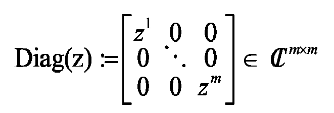
Diagonalmatrix mit Diagonale z und allen übrigen Elementen 0.Diagonal matrix with diagonal z and all other elements 0.

Insbesondere bezeichnet den

Figure imgb0075
m -dimensionalen Euklidischen Vektorraum mit dem Skalarprodukt x T y = Σ i = 1 m x i y i
Figure imgb0076
für x,y
Figure imgb0077
, und
Figure imgb0078
bezeichnet den m- dimensionalen unitären Vektorraum mit dem Skalarprodukt w H z = Σ i = 1 m w i z i
Figure imgb0079
für w,z ∈ ; für
Figure imgb0080
x
Figure imgb0081
bzw. z
Figure imgb0082
bezeichnet x 2 : = x T x +
Figure imgb0083
bzw. z 2 : = z H z +
Figure imgb0084
die Euklidische bzw. unitäre Vektornorm im
Figure imgb0085
bzw.
Figure imgb0086
. Der Vektor 0 m : = 0 0 0 m
Figure imgb0087
bzw. 1 m : = 1 1 m
Figure imgb0088
mit allen Komponenten 0 bzw. 1 wird Nullvektor bzw. Einsvektor genannt. Die Matrix 0 m × n 0 m × n
Figure imgb0089
mit allen Komponenten 0 wird m × n -Nullmatrix und die Matrix I m
Figure imgb0090
mit Diagonalelementen 1 und allen übrigen Elementen 0 wird m × m -Identitätsmatrix genannt.In particular, the designated
Figure imgb0075
m -dimensional Euclidean vector space with the scalar product x T y = Σ i = 1 m x i y i
Figure imgb0076
for x , y
Figure imgb0077
, and
Figure imgb0078
denotes the m- dimensional unitary vector space with the scalar product w H z = Σ i = 1 m w ~ i z i
Figure imgb0079
for w, z ∈; For
Figure imgb0080
x
Figure imgb0081
or z
Figure imgb0082
designated x 2 : = x T x + ~
Figure imgb0083
respectively. z 2 : = z H z + ~
Figure imgb0084
the Euclidean or unitary vector norm in
Figure imgb0085
respectively.
Figure imgb0086
, The vector 0 m : = 0 0 0 m
Figure imgb0087
respectively. 1 m : = 1 1 m
Figure imgb0088
with all components 0 or 1 is called zero vector or one-vector. The matrix 0 m × n 0 m × n
Figure imgb0089
with all components 0, m × n zero matrix and the matrix I m
Figure imgb0090
with diagonal elements 1 and all other elements 0 m × m identity matrix is called.

Für Z

Figure imgb0091
(
Figure imgb0092
=
Figure imgb0093
oder
Figure imgb0094
=
Figure imgb0095
) bezeichnet (Z) := { w
Figure imgb0096
m | w = Z·z,z
Figure imgb0097
} ⊂
Figure imgb0098
den Wertebereich von Z , Z+
Figure imgb0099
bezeichnet die Moore-Penrose Pseudo-Inverse von Z , wie beispielsweise in §III.1.1 des Buches " G. W. Stewart & J-G. Sun: Matrix Perturbation Theory; Academic Press, Inc., Boston, 1990 " erläutert, und P Z = Z·Z +
Figure imgb0100
bzw.
Figure imgb0101
bezeichnen die orthogonalen Projektionen von
Figure imgb0102
auf (
Figure imgb0103
Z )
Figure imgb0104
bzw. auf das orthogonale Komplement [( Z )]┴⊂
Figure imgb0105
von
Figure imgb0106
(Z) in
Figure imgb0107
, wie beispielsweise in §III.1.2 des obengenannten Buches erläutert. Für Z
Figure imgb0108
bezeichnet Rang(Z)
Figure imgb0109
den Rang von Z , d. h. die Dimension des Unterraumes (Z)
Figure imgb0110
. Hat Z
Figure imgb0111
vollen Rang m, so ist Z invertierbar, und für ihre Inverse Z -1 gilt Z += Z -1.For Z
Figure imgb0091
(
Figure imgb0092
=
Figure imgb0093
or
Figure imgb0094
=
Figure imgb0095
) designated ( Z ): = { w
Figure imgb0096
m | w = Z · z, z
Figure imgb0097
} ⊂
Figure imgb0098
the range of values of Z , Z +
Figure imgb0099
refers to the Moore-Penrose pseudo-inverse of Z , as for example in §III.1.1 of the book " GW Stewart & JG. Sun: Matrix perturbation theory; Academic Press, Inc., Boston, 1990 "and P Z = Z · Z +
Figure imgb0100
respectively.
Figure imgb0101
denote the orthogonal projections of
Figure imgb0102
on (
Figure imgb0103
Z )
Figure imgb0104
or to the orthogonal complement [( Z )] ┴⊂
Figure imgb0105
from
Figure imgb0106
( Z ) in
Figure imgb0107
as explained, for example, in §III.1.2 of the above-mentioned book. For Z
Figure imgb0108
denotes rank (Z)
Figure imgb0109
the rank of Z , ie the dimension of the subspace ( Z )
Figure imgb0110
, Has Z
Figure imgb0111
full rank m, as Z is invertible, and its inverse Z -1 + Z applies = Z -1.

Der Erwartungswert der Zufallsmatrix Z

Figure imgb0112
(
Figure imgb0113
=
Figure imgb0114
oder
Figure imgb0115
=
Figure imgb0116
) wird mit
Figure imgb0117
[Z]
Figure imgb0118
bezeichnet.The expectation value of the random matrix Z
Figure imgb0112
(
Figure imgb0113
=
Figure imgb0114
or
Figure imgb0115
=
Figure imgb0116
) will with
Figure imgb0117
[ Z ]
Figure imgb0118
designated.

Nachfolgend werden die physikalischen Verhältnisse des Signalempfangs eines Phasenmessers mathematisch modelliert.Subsequently, the physical conditions of the signal reception of a phase meter are mathematically modeled.

Die gleichzeitig zu vermessenden K

Figure imgb0119
Ziele, wobei K bekannt oder unbekannt sein kann, in unbekannten unterschiedlichen Distanzen D 1 ,D 2,···,D K
Figure imgb0120
vom Sender/Empfänger werden zeitlich sequentiell mit N
Figure imgb0121
periodischen Signalen bekannter Halbwellenlängen ( 1 - 0 ) Λ 1 > Λ 2 > > Λ N > 0
Figure imgb0122
angestrahlt, bei denen es sich um intensitätsmodulierte Licht- oder Infrarotwellen, um Mikro-, Schall- oder Ultraschallwellen oder um andersartige Wellen handeln kann.The K to be measured simultaneously
Figure imgb0119
Targets, where K may be known or unknown, in unknown different distances D 1 , D 2 , ···, D K
Figure imgb0120
from the transmitter / receiver become temporally sequential with N
Figure imgb0121
periodic signals of known half-wavelengths ( 1 - 0 ) Λ 1 > Λ 2 > > Λ N > 0
Figure imgb0122
illuminated, which may be intensity modulated light or infrared waves, micro, sonic or ultrasonic waves or other types of waves.

Das von einigen oder allen K Zielen reflektierte n -te Signal wird vom baulich meist nahe oder unmittelbar neben dem Sender liegenden Empfänger detektiert, elektrisch gewandelt, gefiltert und während In

Figure imgb0123
Perioden M
Figure imgb0124
mal pro Periode äquitemporal abgetastet, wobei die je eine Periode auseinander liegenden In digitalen Abtastwerte zu den digitalen Distanzsignaldaten s n m
Figure imgb0125
gemittelt werden können, 1 m M, 1 n N. The n- th signal reflected from some or all K targets is detected by the receiver, which is structurally close to or immediately adjacent to the transmitter, is electrically converted, filtered, and I n
Figure imgb0123
Periods M
Figure imgb0124
sampled equitemporally per period, with the one period apart I n digital samples to the digital distance signal data s n m
Figure imgb0125
can be averaged, 1 m M, 1 n N.

Für stationäre Ziele, deren Positionen, Lagen, Formen und Reflexionseigenschaften bezüglich des Sender/Empfängers während der Messung nicht ändern, sind die Gleichungen 1 - 1 s n m = a n + Σ k = 1 K A n k Σ n D k Λ n + y n + m - 1 M + w n m , 1 m M 1 n N ,

Figure imgb0126
ein zweckdienliches mathematisches Modell der Distanzsignaldaten s n m ,
Figure imgb0127
wobei den in (1-1) auftretenden, noch nicht erklärten Symbolen folgende Bedeutung zukommt:
Σn :
Figure imgb0128
Figure imgb0129
  Signalform des n -ten Signals: zweimal stetig differenzierbare periodische Funktion der Periode 1, 1≤n≤N,
y n [ - 1 2 , 1 2 [
Figure imgb0130
  Phasenlage des n -ten Signals, 1≤n≤N,
A n k +
Figure imgb0131
  Amplitude des vom k -ten Ziel reflektierten n -ten Signals, 1 k K, 1 n N,
an
Figure imgb0132
  Gleichstromanteil des n -ten Signals, 1≤n≤N,
w n m
Figure imgb0133
  Rauschanteil von s n m ,
Figure imgb0134
, 1 m M, 1 n N. For stationary targets whose positions, positions, shapes and reflectivity with respect to the transceiver do not change during the measurement, the equations are 1 - 1 s n m = a n + Σ k = 1 K A n k Σ n D k Λ n + y n + m - 1 M + w n m . 1 m M 1 n N .
Figure imgb0126
an expedient mathematical model of the distance signal data s n m .
Figure imgb0127
where the following not yet explained symbols appear in (1-1):
Σ n :
Figure imgb0128
Figure imgb0129
Signal form of the nth signal: twice continuously differentiable periodic function of the period 1, 1 ≤n≤N,
y n [ - 1 2 . 1 2 [
Figure imgb0130
Phase angle of the nth signal, 1 ≤n≤N,
A n k +
Figure imgb0131
Amplitude of the n- th signal reflected from the k- th target, 1 k K, 1 n N,
a n
Figure imgb0132
DC component of the nth signal, 1 ≤n≤N,
w n m
Figure imgb0133
Noise from s n m .
Figure imgb0134
, 1 m M, 1 n N.

Aufgabe der Signalverarbeitung ist es, aus den M·N Zahlen s n m ,

Figure imgb0135
1 m M, 1 n N , die unbekannten Distanzen D 1 ,···,D K
Figure imgb0136
zu ermitteln. Damit sie dazu befähigt ist, muss sie das "Systemverhalten" kennen, d.h. von den in (1-1) auftretenden Variablen müssen einige als bekannt vorausgesetzt werden. Diesbezügliche Modellhypothesen lassen sich konziser formulieren, wenn die Gleichungen (1-1) als Matrix-Gleichung geschrieben werden. Dazu werden die dimensionslosen Variablen 1 - 2 d : = 1 Λ 1 D 1 D K K & λ : = [ 1 Λ 1 / Λ 2 Λ 1 / Λ N ] [ 1 , [ N 1 - 0 ,
Figure imgb0137
die Vektoren 1 - 3 x : = 1 M [ 0 1 M - 1 ] [ 0 , 1 [ M , y : = y 1 y N [ - 1 2 , 1 2 [ N , a : = [ a 1 a N ] N
Figure imgb0138
die Matrizen 1 - 4 A : = [ A 1 1 A N 1 A 1 K A N k ] + K × N & S : = [ s 1 1 s N 1 s 1 M s N M ] , W : = [ w 1 1 w N 1 w 1 M w N M ] M × N
Figure imgb0139
sowie die Funktion Σ:
Figure imgb0140
Figure imgb0141
, 1 - 5 Σ ( X ) : = [ Σ 1 X 1 1 Σ N X N 1 Σ 1 X 1 M Σ N X N M ] M × N , X M × N
Figure imgb0142
eingeführt, mittels denen die M·N skalaren Gleichungen (1-1) in der das Messsignal-Modell repräsentierenden Matrix-Gleichung 1 - 6 S = 1 - 25 1 - 1 1 M a T + Σ k = 1 K [ 1 M A k : ] Σ 1 M d k λ + y T + x 1 N T + W
Figure imgb0143
aufgehen.The task of the signal processing is, from the M · N numbers s n m .
Figure imgb0135
1 m M, 1 n N , the unknown distances D 1 , ···, D K
Figure imgb0136
to investigate. In order for it to be capable, it must know the "system behavior", ie of the variables occurring in (1-1), some must be assumed to be known. Model hypotheses can be formulated more concisely when equations (1-1) are written as a matrix equation. These are the dimensionless variables 1 - 2 d : = 1 Λ 1 D 1 D K K & λ : = [ 1 Λ 1 / Λ 2 Λ 1 / Λ N ] [ 1 . [ N 1 - 0 .
Figure imgb0137
the vectors 1 - 3 x : = 1 M [ 0 1 M - 1 ] [ 0 . 1 [ M . y : = y 1 y N [ - 1 2 . 1 2 [ N . a : = [ a 1 a N ] N
Figure imgb0138
the matrices 1 - 4 A : = [ A 1 1 A N 1 A 1 K A N k ] + K × N & S : = [ s 1 1 s N 1 s 1 M s N M ] . W : = [ w 1 1 w N 1 w 1 M w N M ] M × N
Figure imgb0139
as well as the function Σ :
Figure imgb0140
Figure imgb0141
. 1 - 5 Σ ( X ) : = [ Σ 1 X 1 1 Σ N X N 1 Σ 1 X 1 M Σ N X N M ] M × N . X M × N
Figure imgb0142
introduced by means of which the M · N scalar equations (1-1) in the matrix equation representing the measurement signal model 1 - 6 S = 1 - 25 1 - 1 1 M a T + Σ k = 1 K [ 1 M A k : ] Σ 1 M d k λ + y T + x 1 N T + W
Figure imgb0143
rise up.

Im folgenden werden die Voraussetzungen analysiert, unter denen Gleichung (1-6) für gegebene Distanzsignaldaten S

Figure imgb0144
nach der primär interessierenden Variablen d
Figure imgb0145
aufgelöst werden kann. Modellgemäss sind die Systemkonfigurationsparameter M,N
Figure imgb0146
(und mithin x [0,1[ M ) und λ + N
Figure imgb0147
bekannt, während die Parameter a
Figure imgb0148
, A + K × N
Figure imgb0149
und y [ - 1 2 , 1 2 [ N
Figure imgb0150
unbekannt sind. Die Identität 1 - 7 d k λ + y = d k + δ λ + y - δ λ , δ , k 1 K ,
Figure imgb0151
verdeutlicht, dass d
Figure imgb0152
unter günstigen Umständen dann eindeutig bestimmbar ist, wenn hinreichende Kenntnis über y [ - 1 2 , 1 2 [ N
Figure imgb0153
vorliegt. Zudem müssen offensichtlich auch die Signalformen Σn :
Figure imgb0154
Figure imgb0155
, 1≤ n N, zumindest partiell bekannt sein.In the following the assumptions are analyzed, under which equation (1-6) for given distance signal data S
Figure imgb0144
after the primary variable d
Figure imgb0145
can be resolved. According to the model, the system configuration parameters are M, N
Figure imgb0146
(and therefore x [0,1 [ M ) and λ + N
Figure imgb0147
while the parameters a
Figure imgb0148
. A + K × N
Figure imgb0149
and y [ - 1 2 . 1 2 [ N
Figure imgb0150
are unknown. The identity 1 - 7 d k λ + y = d k + δ λ + y - δ λ . δ . k 1 K .
Figure imgb0151
clarifies that d
Figure imgb0152
under favorable circumstances then clearly definable, if sufficient knowledge about y [ - 1 2 . 1 2 [ N
Figure imgb0153
is present. In addition, obviously the signal forms Σ n :
Figure imgb0154
Figure imgb0155
, 1≤ be partially known n N, at least.

Die übliche Art, die erforderliche Kenntnis über y [ - 1 2 , 1 2 [ N

Figure imgb0156
und über Σ:
Figure imgb0157
Figure imgb0158
zu erlangen, also Systemidentifikation zu betreiben, ist folgende: Die N periodischen Signale mit Halbwellenlängen (1-0) werden vor und/oder nach der Distanzmessung über eine geräteinterne Referenzstrecke der Länge 2-D 0
Figure imgb0159
bzw. via ein geräteinternes Ziel im Abstand D 0
Figure imgb0160
vom Sender zum Empfänger geführt, wo sie in gleicher Weise wie die Distanzmesssignale abgetastet und zu digitalen Kalibriersignaldaten s ± n m
Figure imgb0161
gemittelt werden, 1≤m≤M, 1≤n≤N, wobei der Subskript - die Präkalibrierung (vor der Messung) und der Subskript + die Postkalibrierung (nach der Messung) kennzeichnet. Die Kalibriersignaldaten werden deshalb auch gemäss (1-1) bzw. (1-6) modelliert, jedoch mit K = 1 und d = d 0
Figure imgb0162
, 1 - 8 d 0 : = D 0 Λ 1 .
Figure imgb0163
The usual way, the required knowledge about y [ - 1 2 . 1 2 [ N
Figure imgb0156
and about Σ :
Figure imgb0157
Figure imgb0158
To obtain, ie to operate system identification, is the following: The N periodic signals with half-wavelengths (1-0) before and / or after the distance measurement via a device-internal reference distance of length 2- D 0
Figure imgb0159
or via device-internal target at a distance D 0
Figure imgb0160
from the transmitter to the receiver where they are sampled in the same way as the distance measurement signals and to digital calibration signal data s ± n m
Figure imgb0161
1 ≤m≤M, 1 ≤n≤N, where the subscript - the pre-calibration (before the measurement) and the subscript + the post-calibration (after the measurement). The calibration signal data are therefore also modeled according to (1-1) or (1-6), but with K = 1 and d = d 0
Figure imgb0162
. 1 - 8th d 0 : = D 0 Λ 1 ,
Figure imgb0163

Bei uniformer Sendeleistung des Phasenmessers während der gesamten Messung, die modellgemäss vorausgesetzt wird, kann ohne Einschränkung der Allgemeinheit 1 - 9 A - = A + : = 1 N T

Figure imgb0164
gesetzt werden, sodass die Matrix-Gleichung 1 - 10 S ± = 1 - 89 K = 1 1 - 6 1 M a ± T + Σ 1 M d 0 λ + y ± T + x 1 N T + W ±
Figure imgb0165
resultiert. Die Festsetzung (1-9) "normiert" die im Messsignal-Modell (1-6) auftretenden Zielamplituden: A n k
Figure imgb0166
ist die Intensität des vom k -ten Ziel reflektierten n -ten Signals, 1 k K, 1 n N, gemessen in dimensionslosen Vielfachen der Amplitude des internen Zieles.For uniform transmission power of the phase meter during the entire measurement, which is assumed to be model-based, without loss of generality 1 - 9 A - = A + : = 1 N T
Figure imgb0164
be set so that the matrix equation 1 - 10 S ± = 1 - 89 K = 1 1 - 6 1 M a ± T + Σ 1 M d 0 λ + y ± T + x 1 N T + W ±
Figure imgb0165
results. The determination (1-9) "normalizes" the target amplitudes occurring in the measurement signal model (1-6): A n k
Figure imgb0166
is the intensity of the k th reflected target n-th signal, 1 k K, 1 n N, measured in dimensionless multiples of the amplitude of the internal target.

Die Voraussetzungen 'uniforme Sendeleistung' und 'stationäre Ziele' lassen es geboten erscheinen, die Zielamplituden als für alle Sendesignale gleich zu modellieren, also 1 - 11 A = A : 1 1 N T + K × N

Figure imgb0167
zu fordern. Die Praxis zeigt jedoch, dass (1-11) der Realität häufig widerspricht, was plausibel ist, da das Medium, durch das Distanzen gemessen werden, typischerweise die Erdatmosphäre, während der Messung oft instationär ist. Realistischer ist die Annahme, die Zielamplituden unterschiedlicher Distanzmesssignale seien proportional zueinander, die durch die Forderung 1 - 12 Rang A = 1
Figure imgb0168
ausgedrückt werden kann. Wegen Rang(A) ≤ K ist (1-12) nur im Mehrzielfall K > 1 eine Einschränkung, die in gewissen Situationen unrealistisch ist, etwa dann, wenn das Medium, durch das gemessen wird, hochgradig inhomogen und instationär ist. Die Gleichungen (1-11) und (1-12) sind daher lediglich optionale Ergänzungen des Messsignal-Modells (1-6).The prerequisites 'uniform transmission power' and 'stationary targets' make it imperative that the Target amplitudes as for all transmission signals to model the same, ie 1 - 11 A = A : 1 1 N T + K × N
Figure imgb0167
to promote. However, practice shows that (1-11) often contradicts reality, which is plausible because the medium through which distances are measured is typically the Earth's atmosphere, often unsteady during measurement. More realistic is the assumption that the target amplitudes of different distance measuring signals are proportional to each other, by the demand 1 - 12 rank A = 1
Figure imgb0168
can be expressed. Because of rank ( A ) ≤ K , (1-12) is a constraint only in the multi-objective case K > 1 , which is unrealistic in certain situations, such as when the medium by which it is measured is highly inhomogeneous and unsteady. Equations (1-11) and (1-12) are therefore only optional additions to the measurement signal model (1-6).

Die Identität (1-7), die auch für k = 0 mit y ± anstelle von y gilt, zeigt, dass y ± [ - 1 2 , 1 2 [ N

Figure imgb0169
bestenfalls dann aus den Kalibriersignaldaten S±
Figure imgb0170
bestimmt werden kann, wenn d 0
Figure imgb0171
bekannt ist, was modellgemäss vorausgesetzt werden kann, da eine geräteinterne Referenzstrecke bzw. ein geräteinternes Ziel vorrichtungsseitig realisiert und präzise vermessen werden kann. Wird nur eine (Prä- oder Post-) Kalibrierung durchgeführt, so gibt es keine sinnvolle Alternative zur "stationären" Modellhypothese 1 - 13 y = y - bzw . y = y + ,
Figure imgb0172
die identische Phasenlagen von Distanz- und Kalibriermesssignalen postuliert. Dieses Postulat stipuliert Driftfreiheit der Empfangselektronik und ist mithin realitätsfern. Werden eine Prä- und eine Postkalibrierung durchgeführt, so kann ein die physikalischen Gegebenheiten realistischer beschreibender instationärer Zusammenhang zwischen den Phasen postuliert werden. Ein einfaches deterministisches Phasendrift-Modell ist die gewöhnliche Differentialgleichung erster Ordnung 1 - 14 y t t = v y - y t , t , mit v + N & y N ,
Figure imgb0173
mit der Lösungsmenge 1 - 15 y t = 1 - 14 y + η e - t v , t , η N ,
Figure imgb0174
die so interpretiert wird: Die Phasen y
Figure imgb0175
- da die Signale modellgemäss 1-periodische Funktionen sind, kann y [ - 1 2 , 1 2 [ N
Figure imgb0176
durch die Spezifikation y
Figure imgb0177
ersetzt werden - wurden, beispielsweise durch Schaltvorgänge, aus ihren modellgemäss unterstellten stationären Gleichgewichtslagen y
Figure imgb0178
bewegt, in die sie nun mit Geschwindigkeiten zurückkehren, die proportional zu ihren Auslenkungen aus den Gleichgewichtslagen sind, wobei v + N
Figure imgb0179
als Proportionalitätsfaktoren eingeführt werden können.The identity (1-7), which also holds for k = 0 with y ± instead of y , shows that y ± [ - 1 2 . 1 2 [ N
Figure imgb0169
at best then from the calibration signal data S ±
Figure imgb0170
can be determined if d 0
Figure imgb0171
It is known what can be assumed as a model, since a device-internal reference distance or a device-internal target device-side realized and can be precisely measured. If only one (pre- or post-) calibration is performed, then there is none meaningful alternative to the "stationary" model hypothesis 1 - 13 y = y - respectively , y = y + .
Figure imgb0172
the identical phase positions of distance and Kalibriermesssignalen postulated. This postulate stipulates drift-free of the receiving electronics and is therefore far from reality. If a pre-calibration and a post-calibration are carried out, a transient relationship between the phases describing the physical conditions more realistically can be postulated. A simple deterministic phase drift model is the ordinary differential equation of the first order 1 - 14 y t t = v y - y t . t . With v + N ~ & y N .
Figure imgb0173
with the amount of solution 1 - 15 y t = 1 - 14 y + η e - t v . t . η N .
Figure imgb0174
which is interpreted as follows: The phases y
Figure imgb0175
- Since the signals are model-1-periodic functions, can y [ - 1 2 . 1 2 [ N
Figure imgb0176
through the specification y
Figure imgb0177
were replaced - for example, by switching operations, from their assuming according to the model stationary equilibrium positions y
Figure imgb0178
into which they now return at speeds proportional to their deflections from the equilibrium positions, where v + N ~
Figure imgb0179
can be introduced as proportionality factors.

Bezeichnet τ - n +

Figure imgb0180
bzw. τ + n +
Figure imgb0181
die mittlere Zeit, die zwischen der Präkalibriermessung und der Distanzmessung bzw. zwischen der Distanzmessung und der Postkalibriermessung mit dem n -ten Signal verstreicht, 1 n N, so ergeben sich aus (1-15) mit Hilfe der Vektoren 1 - 16 τ ± : = τ ± 1 τ ± N + N
Figure imgb0182
die Beziehungen 1 - 17 y 1 - 15 y + η & y ± 1.16 1 - 15 y + η e v τ ± ,
Figure imgb0183
wenn in (1-15) für jede Komponente die Zeit-Skala individuell so gewählt wird, dass jede Distanzmessung zur Zeit 0 stattfindet. Aus (1-17) folgt weiter 1 - 18 y 1 - 17 y + + 1 N - e - v τ + η 1 - 17 y + + 1 N - e - v τ + ] [ y - - y + e v τ - - e - v τ + = [ 1 N - e - v τ + ] y - + [ e v τ - - 1 N ] y + e v τ - - e - v τ + ,
Figure imgb0184
wobei im Falle vn = 0 die rechte Seite von (1-18) gemäss der L'Hôpital'schen Regel durch den Grenzwert 1 - 19 lim v n 0 [ 1 - e - v n τ + n ] y - n + [ e v n τ - n - 1 ] y + n e v n τ - n - e - v n τ + n = lim v n 0 v n [ 1 - e - v n τ + n ] y - n + [ e v n τ - n - 1 ] y + n v n e v n τ - n - e - v n τ + n = τ - n y + n + τ + n y - n τ - n + τ + n
Figure imgb0185
ersetzt wird, n {1,···,N}, und da Kalibriermessungen u.a. dem Zweck dienen, via y ±
Figure imgb0186
Kenntnis über die Phasenlagen y
Figure imgb0187
zu erlangen, impliziert (1-18), dass die Variablen v , τ - , τ + + N
Figure imgb0188
modellgemäss als bekannt vorausgesetzt werden müssen. Das ist nicht unrealistisch, denn die Zeiten τ ± + N
Figure imgb0189
können gemessen werden, und v + N
Figure imgb0190
kann aus speziellen Messungen ermittelt werden, bei denen anstelle von externen Zielen das interne Ziel vermessen wird, das interne Ziel also dreimal hintereinander vermessen wird.Designated τ - n +
Figure imgb0180
respectively. τ + n +
Figure imgb0181
the average time that elapses with the n th signal between the Präkalibriermessung and the distance measurement or between the distance measurement and the Postkalibriermessung, 1 n N, so resulting from (1-15) with the aid of the vectors 1 - 16 τ ± : = τ ± 1 τ ± N + N
Figure imgb0182
the relationships 1 - 17 y 1 - 15 y + η & y ± 1.16 1 - 15 y + η e v τ ± .
Figure imgb0183
if in (1-15) for each component the time scale is chosen individually such that each distance measurement takes place at time zero. Off (1-17) continues 1 - 18 y 1 - 17 y + + 1 N - e - v τ + η 1 - 17 y + + 1 N - e - v τ + ] [ y - - y + e v τ - - e - v τ + = [ 1 N - e - v τ + ] y - + [ e v τ - - 1 N ] y + e v τ - - e - v τ + .
Figure imgb0184
in the case of v n = 0, the right side of (1-18) according to L'Hôpital's rule by the limit 1 - 19 lim v n 0 [ 1 - e - v n τ + n ] y - n + [ e v n τ - n - 1 ] y + n e v n τ - n - e - v n τ + n = lim v n 0 v n [ 1 - e - v n τ + n ] y - n + [ e v n τ - n - 1 ] y + n v n e v n τ - n - e - v n τ + n = τ - n y + n + τ + n y - n τ - n + τ + n
Figure imgb0185
is replaced, n {1, ···, N }, and since calibration measurements serve the purpose, among other things, via y ±
Figure imgb0186
Knowledge about the phase positions y
Figure imgb0187
To obtain implies (1-18) that the variables v . τ - . τ + + N
Figure imgb0188
According to the model, they must be assumed to be known. That's not unrealistic, because times τ ± + N
Figure imgb0189
can be measured, and v + N
Figure imgb0190
can be determined from special measurements in which the internal target is measured instead of external targets, so the internal target is measured three times in succession.

Aus (1-17) folgt 1 - 20 y ± 1 - 17 y - 1 N - e v τ ± η y - a ± η mit a ± : = 1 N - e v τ ± N ,

Figure imgb0191
was in (1-10) eingesetzt die ein Kalibriersignal-Modell konstituierenden Matrix-Gleichungen 1 - 21 S ± = 1 - 20 1 - 10 1 M a ± T + Σ 1 M d 0 λ + y - a ± η T + x 1 N T + W ±
Figure imgb0192
ergibt.From (1-17) follows 1 - 20 y ± 1 - 17 y - 1 N - e v τ ± η y - a ± η with a ± : = 1 N - e v τ ± N .
Figure imgb0191
what in (1-10) uses the matrix equations of a calibration signal model 1 - 21 S ± = 1 - 20 1 - 10 1 M a ± T + Σ 1 M d 0 λ + y - a ± η T + x 1 N T + W ±
Figure imgb0192
results.

Die Gleichungen (1-6) und (1-21) sind Bestandteile des (Gesamt-)Signalmodells, das optional durch die Nebenbedingung (1-11) oder (1-12) ergänzt werden kann, und das der Signalverarbeitung zugrunde gelegt wird.Equations (1-6) and (1-21) are components of the (overall) signal model, which can optionally be supplemented by constraint (1-11) or (1-12), and used as a basis for signal processing.

Die modellgemäss vorausgesetzte 1-Periodizität der Funktion Σ:

Figure imgb0193
Figure imgb0194
und (1-6) implizieren, dass im Falle λ ∈
Figure imgb0195
, in dem alle Komponenten von λ rationale Zahlen sind, unendlich viele d
Figure imgb0196
dieselben Distanzsignaldaten S
Figure imgb0197
erzeugen. Da
Figure imgb0198
in
Figure imgb0199
dicht ist, d.h. jeder Vektor in
Figure imgb0200
beliebig genau durch einen Vektor aus
Figure imgb0201
approximiert werden kann, ist in der Praxis unendlichfache Mehrdeutigkeit bzw. Ambiguität bezüglich d
Figure imgb0202
allgegenwärtig; Eindeutigkeit kann nur durch zusätzliche Auflagen erzwungen werden. Üblicherweise wird 1 - 22 d - 1 K d < d + 1 K
Figure imgb0203
mit vorgegebenen Messbereichsgrenzen d-< d + bzw. D - = 1 - 2 Λ 1 d - < D + = 1 - 2 Λ 1 d +
Figure imgb0204
verlangt, wobei die Schranken d ±
Figure imgb0205
bzw. D±
Figure imgb0206
so zu wählen sind, dass Eindeutigkeit garantiert ist.The model-assumed 1-periodicity of the function Σ :
Figure imgb0193
Figure imgb0194
and (1-6) imply that in the case of λ ∈
Figure imgb0195
in which all components of λ are rational numbers, infinitely many d
Figure imgb0196
the same distance signal data S
Figure imgb0197
produce. There
Figure imgb0198
in
Figure imgb0199
is dense, ie every vector in
Figure imgb0200
arbitrary exactly by a vector
Figure imgb0201
can be approximated, is in practice infinitely ambiguity or ambiguity with respect to d
Figure imgb0202
omnipresent; Uniqueness can only be enforced by additional requirements. Usually will 1 - 22 d - 1 K d < d + 1 K
Figure imgb0203
with predetermined measuring range limits d - <d + or D - = 1 - 2 Λ 1 d - < D + = 1 - 2 Λ 1 d +
Figure imgb0204
requires, where the bounds d ±
Figure imgb0205
or D ±
Figure imgb0206
are to be chosen so that uniqueness is guaranteed.

Schliesslich sind auch die Rauschanteile W,W ±

Figure imgb0207
der Distanz- und Kalibriersignaldaten S,S ±
Figure imgb0208
unbekannt. Damit die Gleichungen (1-6) und (1-21) dennoch nach d
Figure imgb0209
"aufgelöst" werden können, muss das statistische Verhalten des Rauschens - zumindest strukturell - bekannt sein.Finally, the noise components W, W ±
Figure imgb0207
the distance and calibration signal data S, S ±
Figure imgb0208
unknown. So that the equations (1-6) and (1-21) still after d
Figure imgb0209
"resolved", the statistical behavior of the noise - at least structurally - must be known.

Deshalb wird W - W W + 3 M × N

Figure imgb0210
als Zufallsmatrix mit Wahrscheinlichkeitsdichte n : 3 M × N +
Figure imgb0211
modelliert, die - allenfalls bis auf einige sie charakterisierende Parameter - als bekannt vorausgesetzt wird. Die Modellierung des Rauschens als Zufallsmatrix und die Spezifizierung ihrer Wahrscheinlichkeitsdichte n : 3 M × N +
Figure imgb0212
ist ein (1-6) und (1-21) ergänzender Bestandteil des Signalmodells.That's why W - W W + 3 M × N
Figure imgb0210
as a random matrix with probability density n : 3 M × N + ~
Figure imgb0211
which is presumed to be known, except for a few parameters characterizing it. The modeling of noise as a random matrix and the specification of its probability density n : 3 M × N + ~
Figure imgb0212
is a (1-6) and (1-21) complementary component of the signal model.

Die mathematisch einfachste, wegen der Beschränktheit der Distanz- und Kalibriersignaldaten S,S ±

Figure imgb0213
jedoch etwas realitätsferne Modellannahme betreffend n ist Normalverteilung mit
Figure imgb0214
wobei C n , C ± n M × M
Figure imgb0215
symmetrische positiv-definite Matrizen bezeichnen, die als bekannt vorausgesetzt werden, 1 n N, δnl = 1 ist, falls n = l, und δ nl = 0 andernfalls, und σ
Figure imgb0216
einen unbekannten Skalierungsfaktor bezeichnet. Modellhypothese (1-23) postuliert insbesondere die Unkorreliertheit der Distanz- und Kalibriersignaldaten unterschiedlicher Empfangssignale; sie reflektiert den Sachverhalt, dass Signale unterschiedlicher Halbwellenlängen sowie Distanz- und Kalibriermesssignale zeitlich getrennt gesendet und empfangen werden. Der unbekannte Skalierungsfaktor σ
Figure imgb0217
macht deutlich, dass lediglich die relativen Rauschverhältnisse, nicht aber die absoluten, als bekannt vorausgesetzt werden. Aus (1-23) ergibt sich die Wahrscheinlichkeitsdichte 1 - 24 n W - W W + = 1 - 23 exp - 1 2 σ 2 Σ n = 1 N W - : n T C - n - 1 W - : n + W : n T C n - 1 W : n + W + : n T C + n - 1 W + : n 2 π σ 2 3 M N 2 Π n = 1 N det C - n det C n det C + n
Figure imgb0218
die der Signalverarbeitung zugrunde gelegt wird.The mathematically simplest, because of the narrowness of Distance and calibration signal data S, S ±
Figure imgb0213
however, some unrealistic model assumption regarding n is normal distribution with
Figure imgb0214
in which C n . C ± n M × M
Figure imgb0215
denote symmetric positive-definite matrices, which are assumed to be known, 1 n N , δ nl = 1 , if n = 1 , and δ nl = 0 otherwise, and σ
Figure imgb0216
denotes an unknown scaling factor. Model hypothesis (1-23) in particular postulates the uncorrelation of the distance and calibration signal data of different received signals; It reflects the fact that signals of different half-wavelengths as well as distance and calibration measuring signals are transmitted and received separately in time. The unknown scaling factor σ
Figure imgb0217
makes it clear that only the relative noise ratios, but not the absolute, are assumed to be known. From (1-23) results the probability density 1 - 24 n W - W W + = 1 - 23 exp - 1 2 σ 2 Σ n = 1 N W - : n T C - n - 1 W - : n + W : n T C n - 1 W : n + W + : n T C + n - 1 W + : n 2 π σ 2 3 M N 2 Π n = 1 N det C - n det C n det C + n
Figure imgb0218
which is the basis of the signal processing.

Es stellt sich die Frage, wie die Signalmodell-Gleichungen (1-6) und (1-21) nach d

Figure imgb0219
[d-·1 K,d+· 1 K [⊂ "aufgelöst" werden sollen. Ein bewährter Ansatz ist, d ∈ [d-· 1 K,d+ ·1 K [ - und gezwungenermassen auch y,η ∈
Figure imgb0220
, a,a±
Figure imgb0221
, A + K × N
Figure imgb0222
und die Σ:
Figure imgb0223
Figure imgb0224
kennzeichnenden Parameter - im Sinne maximaler Likelihood (ML) zu schätzen, wie beispielsweise im Kapitel 18 des Standardwerks " A. Stuart, J. K. Ord & S. Arnold: Kendalls's Advanced Theory of Statistics, Volume 2A, 6th Edition; Arnold, London, 1999 ", beschrieben, d.h. ihnen die Werte ∈ [d-· 1 K,d+· 1 K [ etc. zuzuordnen, welche die Wahrscheinlichkeitsdichte n ( W -,W,W + ) maximieren, wenn die Zufallsmatrizen W,W±
Figure imgb0225
gemäss dem Signalmodell (1-6) und (1-21) durch die Distanz- und Kalibriersignaldaten S,S±
Figure imgb0226
und die Modellparameter substituiert werden. Da die Kovarianzmatrizen C n , C ± n M × M ,
Figure imgb0227
1 n N, - was logisch nicht notwendig, aber praktisch sinnvoll ist - als bekannt vorausgesetzt werden, zeigt ein Standardargument der Schätztheorie, dass diese sog. ML-Schätzwerte [d-·1 K,d+·1 K [, etc. für d [d-·1 K,d+·1 K [, etc. im Falle (1-24) charakterisiert sind als Minimalstelle der Summe 2 - 0 Σ n = 1 N W - : n T C - n - 1 W - : n + W : n T C n - 1 W : n + W + : n T C + n - 1 W + : n ,
Figure imgb0228
in der die Zufallsmatrizen W,W±
Figure imgb0229
gemäss dem Signalmodell (1-6) und (1-21) durch die Distanz- und Kalibriersignaldaten S,S±
Figure imgb0230
und die Modellparameter substituiert werden. Insbesondere sind die ML-Schätzwerte unabhängig vom Skalierungsparameter σ
Figure imgb0231
, was zeigt, dass die ML-Schätzwerte unabhängig vom mittleren Rauschniveau sind, was für deren Güte natürlich nicht zutrifft.The question arises, how the signal model equations (1-6) and (1-21) after d
Figure imgb0219
[ d - · 1 K , d + · 1 K [⊂ "to be resolved". A proven approach is that d ∈ [ d - · 1 K, d + · 1 K [- and, by necessity, y, η ∈
Figure imgb0220
, a, a ±
Figure imgb0221
. A + K × N
Figure imgb0222
and the Σ :
Figure imgb0223
Figure imgb0224
characteristic parameters - in the sense of maximum likelihood (ML), as for example in Chapter 18 of the A. Stuart, JK Ord & S. Arnold: Kendall's Advanced Theory of Statistics, Volume 2A, 6th Edition; Arnold, London, 1999 , ie, assigning to them the values d ∈ [ d - 1 1 K , d + 1 1 K [etc., which maximize the probability density n ( W - , W , W + ) when the random matrices W, W ±
Figure imgb0225
according to the signal model (1-6) and (1-21) by the distance and calibration signal data S, S ±
Figure imgb0226
and the model parameters are substituted. Because the covariance matrices C n . C ± n M × M .
Figure imgb0227
1 n N , - which is logically not necessary, but practically meaningful - assumed to be known, a standard argument of the estimation theory shows that these so-called ML-estimates d [ d - · 1 K , d + · 1 K [ , etc. for d [ d - · 1 K , d + · 1 K [, etc. in the case (1-24) are characterized as the minimum of the sum 2 - 0 Σ n = 1 N W - : n T C - n - 1 W - : n + W : n T C n - 1 W : n + W + : n T C + n - 1 W + : n .
Figure imgb0228
in which the random matrices W, W ±
Figure imgb0229
according to the signal model (1-6) and (1-21) by the distance and calibration signal data S, S ±
Figure imgb0230
and the model parameters be substituted. In particular, the ML estimates are independent of the scaling parameter σ
Figure imgb0231
, which shows that the ML estimates are independent of the mean noise level, which of course does not apply to their quality.

Die vom Signalmodell (1-6) und (1-21) geforderte Kenntnis der Signalformen Σ:

Figure imgb0232
Figure imgb0233
motiviert, diese möglichst einfach zu wählen. Herkömmliche (Einziel-) Phasenmesser verwenden typischerweise sinusoidale Signale unterschiedlicher Frequenzen. Diese klassische Wahl ist im Mehrzielfall unzweckmässig; zweckdienlicher sind Summen von sinusoidalen Grundharmonischen und einigen ihrer tiefsten Oberwellen. Praktisch können diese erzeugt werden, indem nicht-sinusoidale periodische Signale, die einen Grossteil ihrer Energie im niedrigfrequenten Teil ihres Spektrums haben, ausgesendet und ihre von den Zielen reflektierten Echos so Tiefpass-gefiltert werden, dass lediglich die L
Figure imgb0234
niedrigsten Harmonischen ihrer Fourier-Zerlegungen zu den Distanz- und Kalibriersignaldaten beitragen. Für solche Signalformen kann der Ansatz 3 - 0 n t : = Σ l = 1 L b n l cos 2 l π t + n l sin 2 l π t = Re Σ l = 1 L b n l e 2 l π t , t , 1 n N ,
Figure imgb0235
mit den unbekannten Parametern 3 - 1 B : = B 1 1 B N 1 B 1 L B N L L × N , B n l : = 3 - 0 b n l - i n l , 1 l L & Im B n 1 : = 0 , 1 n N ,
Figure imgb0236
verwendet werden, wobei die Bedingung Im B 1 : = 0 N T
Figure imgb0237
die irrelevanten Translations-Freiheitsgrade der Signalformen Σn :
Figure imgb0238
Figure imgb0239
eliminiert, 1≤nN. The knowledge of the signal forms Σ required by the signal model (1-6) and (1-21):
Figure imgb0232
Figure imgb0233
motivated to choose them as simply as possible. Conventional (single) phase meters typically use sinusoidal signals of different frequencies. This classic choice is inappropriate in the multi-target case; more useful are sums of sinusoidal fundamental harmonics and some of their deepest harmonics. In practice, these can be generated by sending out non-sinusoidal periodic signals, which have a large part of their energy in the low-frequency part of their spectrum, and filtering their echoes reflected by the targets in such a way that only the L
Figure imgb0234
lowest harmonics of their Fourier decompositions contribute to the distance and calibration signal data. For such signal forms, the approach 3 - 0 Σ n t : = Σ l = 1 L b n l cos 2 l π t + b ' n l sin 2 l π t = re Σ l = 1 L b n l e 2 l π t . t . 1 n N .
Figure imgb0235
with the unknown parameters 3 - 1 B : = B 1 1 B N 1 B 1 L B N L L × N . B n l : = 3 - 0 b n l - i b ' n l . 1 l L & in the B n 1 : = 0 . 1 n N .
Figure imgb0236
be used, the condition in the B 1 : = 0 N T
Figure imgb0237
the irrelevant translational degrees of freedom of the signal forms Σ n :
Figure imgb0238
Figure imgb0239
eliminated, 1≤ nN.

Den 3·M·N skalaren Signaldaten S,S ±

Figure imgb0240
stehen dann - sofern weder (1-11) noch (1-12) beachtet wird - die K+(4+K+2·L-1)·N unbekannten reellen Parameter d
Figure imgb0241
, y,η
Figure imgb0242
, a , a ± N
Figure imgb0243
, A + K × N
Figure imgb0244
, Re { B } , Im { B } L × N
Figure imgb0245
gegenüber, sodass zumindest 3 - 2 3 M N K + 3 + K + 2 L N bzw . M 1 + K 1 + 1 / N + 2 L 3
Figure imgb0246
sein sollte. In der Praxis wird die Anzahl M der SignalAbtastungen pro Signalperiode viel grösser gewählt als von (3-2) gefordert; zweckdienlich ist die Wahl 3 - 3 K L < M 2 ,
Figure imgb0247
die modellgemäss vorausgesetzt werden kann.The 3 · M · N scalar signal data S, S ±
Figure imgb0240
then, if neither (1-11) nor (1-12) is considered, then the K + ( 4 + K + 2 · L- 1) · N unknown real parameters d
Figure imgb0241
, y, η
Figure imgb0242
. a . a ± N
Figure imgb0243
. A + K × N
Figure imgb0244
. re { B } . in the { B } L × N
Figure imgb0245
opposite, so at least 3 - 2 3 M N K + 3 + K + 2 L N respectively , M 1 + K 1 + 1 / N + 2 L 3
Figure imgb0246
should be. In practice, the number M of signal samples per signal period is much larger than required by (3-2); expedient is the choice 3 - 3 K L < M 2 .
Figure imgb0247
which can be assumed according to the model.

Wird nach gängiger Praxis das Rauschen des n -ten Empfangskanals als mittelwertfreier stationärer Gaussprozess modelliert, und wird angenommen, was üblicher technischer Praxis entspricht, das M -malige äquitemporale Abtasten pro Signalperiode des n -ten Empfangssignals erfolge in ununterbrochener zeitlicher Folge während In

Figure imgb0248
Signalperioden, so zeigt eine wahrscheinlichkeitstheoretische Rechnung, dass die Kovarianzmatrizen C n , C ± n M × M
Figure imgb0249
symmetrische Toeplitz-Matrizen sind, die für genügend kurze Korrelationszeit des Gaussprozesses und für hinreichend grosses In annähernd und im Limes In → ∞ sogar exakt zirkulant sind, 1≤nN. Da 1000 eine typische Grössenordnung für In ist, ist es nicht unrealistisch, die Kovarianzmatrizen C n , C ± n M × M
Figure imgb0250
als ergänzenden Bestandteil des Signalmodells zirkulant vorauszusetzen, 1 n N. If, according to current practice, the noise of the nth receive channel is modeled as a mean-free stationary Gauss process, and it is assumed, which corresponds to usual technical practice, the M- times equitemporal sampling per signal period of the nth receive signal occurs in an uninterrupted temporal sequence during I n
Figure imgb0248
Signal periods, as a probabilistic calculation shows that the covariance matrices C n . C ± n M × M
Figure imgb0249
symmetric Toeplitz matrices are that for sufficiently short correlation time of the Gauss process and for sufficiently large I n approximately and in the limit I n → ∞ are even exactly circulatory, 1≤ nN. Since 1000 is a typical order of magnitude for I n , it is not unrealistic to use the covariance matrices C n . C ± n M × M
Figure imgb0250
presuppose circulant as a complementary part of the signal model, 1 n N.

Die zirkulanten Matrizen Z

Figure imgb0251
sind genau die, welche die diskrete Fourier-Transformation
Figure imgb0252
Figure imgb0253
in
Figure imgb0254
, d.h. die komplexwertige unitäre und symmetrische Matrix mit Elementen 3 - 4 M m : 1 M e - 2 π i ( m - 1 ) - 1 M = 1 M e 2 π i ( m - 1 ) M + 1 - M , 1 m , M ,
Figure imgb0255
unitär diagonalisiert, d.h. für die M Z M H M × M
Figure imgb0256
diagonal ist. Dieser Sachverhalt gestattet, die symmetrischen, positiv definit und zirkulant vorausgesetzten Kovarianzmatrizen C n , C ± n M × M
Figure imgb0257
so darzustellen: 3 - 5 C n = M H Diag σ n 2 M , σ n = σ n 0 σ n M - 1 + M C ± n = M H Diag σ ± n 2 M , σ ± n = σ ± n 0 σ ± n M - 1 + M & σ n m = σ n M - m σ ± n m = σ ± n M - m , 1 m < M 1 n N .
Figure imgb0258
The circulant matrices Z
Figure imgb0251
are exactly what the discrete Fourier transform
Figure imgb0252
Figure imgb0253
in
Figure imgb0254
ie the complex valued unitary and symmetric matrix with elements 3 - 4 M m' m : 1 M e - 2 π i ( m - 1 ) m' - 1 M = 1 M e 2 π i ( m - 1 ) M + 1 - m' M . 1 m . m' M .
Figure imgb0255
unitary diagonalized, ie for the M Z M H M × M
Figure imgb0256
is diagonal. This fact allows the symmetric, positive definite and circulatory assumed covariance matrices C n . C ± n M × M
Figure imgb0257
to represent: 3 - 5 C n = M H Diag σ n 2 M . σ n = σ n 0 σ n M - 1 + M C ± n = M H Diag σ ± n 2 M . σ ± n = σ ± n 0 σ ± n M - 1 + M & σ n m = σ n M - m σ ± n m = σ ± n M - m . 1 m < M 1 n N ,
Figure imgb0258

Jede der Matrizen C n , C ± n M × M

Figure imgb0259
kann also durch ┌ M/2┐ positive Parameter spezifiziert werden. Es wird sich herausstellen, dass die ML-Schätzwerte lediglich von den L Parametern σ - n l , σ n l , σ + n l +
Figure imgb0260
, 1 l L , abhängen, deren Werte mittels eines geeigneten Rauschidentifikations-Verfahrens in Erfahrung gebracht werden können und deshalb modellgemäss als bekannt vorausgesetzt werden.Each of the matrices C n . C ± n M × M
Figure imgb0259
can be specified by ┌ M / 2┐ positive parameters. It will turn out that the ML estimates are only from the 3 · L parameters σ - n l . σ n l . σ + n l +
Figure imgb0260
, 1 l L , whose values can be obtained by means of a suitable noise identification method and are therefore assumed to be known according to the model.

Die ML-Schätzung der unbekannten Parameter des Signalmodells aus den Distanz- und Kalibriersignaldaten S,S±

Figure imgb0261
bzw. die Minimierung von (2-0) ist ein komplexes und äusserst rechenintensives Unterfangen, nicht zuletzt deshalb, weil das Signalmodell zahlreiche Parameter enthält, deren Werte gar nicht interessieren. Es ist deshalb angezeigt, möglichst viele der nicht interessierenden Modellparameter analytisch aus der Minimierung zu eliminieren.The ML estimation of the unknown parameters of the signal model from the distance and calibration signal data S, S ±
Figure imgb0261
or the minimization of (2-0) is a complex and extremely compute-intensive undertaking, not least because the signal model contains numerous parameters whose values are of no interest at all. It is therefore advisable to analytically eliminate as many of the model parameters of no interest as possible from the minimization.

Werden die Gleichungen (1-6), (1-21), (3-0) und (3-5) in die zu minimierende Summe (2-0) eingesetzt, so treten die Matrizen S,S ±

Figure imgb0262
nur noch in den Produkten
Figure imgb0263
·S,
Figure imgb0264
·S ±
Figure imgb0265
auf, und es ist zweckdienlich, deren Elemente, soweit sie benötigt werden, in Polarform zu schreiben: Wegen S,S±
Figure imgb0266
haben
Figure imgb0267
·S,
Figure imgb0268
·S ±
Figure imgb0269
die eindeutigen Darstellungen 4 - 0 M S n 1 + l = M r n l e 2 π i φ n l mit r n l + & φ n l [ - 1 2 , 1 2 [ M S ± n 1 + l = M r ± n l e 2 π i φ ± n l mit r ± n l + & φ ± n l [ - 1 2 , 1 2 [ , 1 l L 1 n N .
Figure imgb0270
If the equations (1-6), (1-21), (3-0) and (3-5) are used in the sum (2-0) to be minimized, then the matrices S, S ± ∈ occur
Figure imgb0262
only in the products
Figure imgb0263
· S,
Figure imgb0264
· S ±
Figure imgb0265
on, and it is expedient to write their elements, as far as they are needed, in polar form: Because of S, S ±
Figure imgb0266
to have
Figure imgb0267
· S,
Figure imgb0268
· S ±
Figure imgb0269
the clear representations 4 - 0 M S n 1 + l = M r n l e 2 π i φ n l With r n l + ~ & φ n l [ - 1 2 . 1 2 [ M S ± n 1 + l = M r ± n l e 2 π i φ ± n l With r ± n l + ~ & φ ± n l [ - 1 2 . 1 2 [ . 1 l L 1 n N ,
Figure imgb0270

Unter Zuhilfenahme der Matrizen 4 - 1 Q , Q ± , + L × N

Figure imgb0271
mit Q n l : = r n l σ n l , Q ± n l : = r ± n l σ n l σ ± n l 2 , n l : = σ n l σ - n l 2 + σ + n l 2 σ - n l σ + n l , 1 l L 1 n N ,
Figure imgb0272
4 - 2 Ψ ± = ψ ± 1 1 ψ ± N 1 ψ ± 1 L ψ ± N L : = [ φ 1 1 φ N 1 φ 1 L φ N L ] - [ φ ± 1 1 φ ± N 1 φ ± 1 L φ ± N L ] ] - 1 , 1 [ L × N ,
Figure imgb0273
und der Vektoren 4 - 3 δ : = d - d 0 1 K K & δ - δ + : = d - - d 0 d + - d 0 2 1 - 22 δ - < δ +
Figure imgb0274
4 - 4 β : = a - a + = 1 - 20 e v τ - - 1 N 1 N - e - v τ + 1 - 16 1 - 14 + N & ζ : = a + η = 1 - 20 1 N - e - v τ + η N ,
Figure imgb0275
(ist v n = 0 , so wird β n : = 4 - 4 lim v n 0 e v τ - - 1 N 1 N - e - v τ + = lim v n 0 v n e v τ - - 1 N v n 1 N - e - v τ + = τ - n τ + n 1 - 16 +
Figure imgb0276
gesetzt, n ∈ {1,···, N }), ergibt sich aus (3-0), (3-5) und (4-0) - (4.4), dass die Minimierung von (2-0) äquivalent ist zur Maximierung der gemäss 4 - 5 £ K , L δ ς A : = Σ n = 1 N Σ l = 1 L Q - n l e 2 π i ψ - n l + l β n ς n + Q n l A : n T e 2 π i l λ n δ + Q + n l e 2 π i ψ + n l - l ς n 2 A : n T e 2 π i l λ n δ 2 + n l 2
Figure imgb0277
definierten Funktion £ K , L : K × N × K × N +
Figure imgb0278
. Die ML-Schätzwerte δ̂ ∈ [δ-· 1 K,δ+, 1 K [, ζ̂ ∈
Figure imgb0279
und A ^ + K × N ,
Figure imgb0280
für die unbekannten Modellparameter δ ∈ [δ-·1 K +·1 K [, ζ ∈
Figure imgb0281
und A + K × N ,
Figure imgb0282
sind mithin charakterisiert als Maximalstelle (δ̂,ζ̂, ) der Funktion £ K,L in [ δ - 1 K , δ + 1 K [ × N × + K × N ,
Figure imgb0283
wobei optional noch Randbedingung (1-11) oder (1-12) beachtet werden kann.With the help of the matrices 4 - 1 Q . Q ± . Q ' + ~ L × N
Figure imgb0271
With Q n l : = r n l σ n l . Q ± n l : = r ± n l σ n l σ ± n l 2 . Q ' n l : = σ n l σ - n l 2 + σ + n l 2 σ - n l σ + n l . 1 l L 1 n N .
Figure imgb0272
4 - 2 Ψ ± = ψ ± 1 1 ψ ± N 1 ψ ± 1 L ψ ± N L : = [ φ 1 1 φ N 1 φ 1 L φ N L ] - [ φ ± 1 1 φ ± N 1 φ ± 1 L φ ± N L ] ] - 1 . 1 [ L × N .
Figure imgb0273
and the vectors 4 - 3 δ : = d - d 0 1 K K & δ - δ + : = d - - d 0 d + - d 0 2 1 - 22 δ - < δ +
Figure imgb0274
4 - 4 β : = a - a + = 1 - 20 e v τ - - 1 N 1 N - e - v τ + 1 - 16 1 - 14 + N & ζ : = a + η = 1 - 20 1 N - e - v τ + η N .
Figure imgb0275
(is v n = 0 . so will β n : = 4 - 4 lim v n 0 e v τ - - 1 N 1 N - e - v τ + = lim v n 0 v n e v τ - - 1 N v n 1 N - e - v τ + = τ - n τ + n 1 - 16 +
Figure imgb0276
set, n ∈ { 1 , ···, N }), it follows from (3-0), (3-5) and (4-0) - (4.4) that the minimization of (2-0) is equivalent is to maximize the according 4 - 5 £ K . L δ ς A : = Σ n = 1 N Σ l = 1 L Q - n l e 2 π i ψ - n l + l β n ς n + Q n l A : n T e 2 π i l λ n δ + Q + n l e 2 π i ψ + n l - l ς n 2 A : n T e 2 π i l λ n δ 2 + Q ' n l 2
Figure imgb0277
defined function £ K . L : K × N × K × N + ~
Figure imgb0278
, The ML estimates δ ∈ [ δ - · 1 K, δ + , 1 K [, ζ ∈
Figure imgb0279
and A ^ + K × N .
Figure imgb0280
for the unknown model parameters δ ∈ [δ - · 1 K , δ + · 1 K [, ζ ∈
Figure imgb0281
and A + K × N .
Figure imgb0282
are thus characterized as the maximum point (δ , ζ , Â ) of the function £ K, L in [ δ - 1 K . δ + 1 K [ × N × + K × N .
Figure imgb0283
where optional boundary condition (1-11) or (1-12) can be considered.

Aus (4-5) ist ersichtlich, dass im Falle λ ∈

Figure imgb0284
die Funktion £ K , L : K × R N × K × N +
Figure imgb0285
bezüglich ihres ersten Argumentes periodisch ist; dies motivierte die Einschränkung (1-22). Aber auch das zweite Argument von £ K,L gibt Anlass zu Unbestimmtheit im ersten Argument, wie am einfachsten Spezialfall K=L=1 dargelegt werden kann: Wegen 4 - 6 e 2 π i ψ - n 1 + β n ς n = e 2 π i ψ + n 1 - ς n ψ - n 1 + β n ς n + = ψ + n 1 - ς n ς n = ς ^ n : = ψ + n 1 - ψ - n 1 - 1 + β n , ,
Figure imgb0286
sind die Zahlen
Figure imgb0287
ℓ ∈
Figure imgb0288
, Kandidaten für Maximalstellen von £ 1,1. Da gezeigt werden kann, dass die komplexen Zahlen
Figure imgb0289
auf dem Einheitskreis in der komplexen Ebene
Figure imgb0290
dicht liegen, falls βn
Figure imgb0291
irrational ist, ist also für beliebige δ [δ-+ [ und A n 1 +
Figure imgb0292
das Supremum über ζ n
Figure imgb0293
des n -ten Summanden von £1,1 4 - 8 Q - n 1 + Q n 1 A n 1 + Q + n 1 2 A n 1 2 + n 1 2
Figure imgb0294

  • ein Ausdruck, der unabhängig von δ ist.
From (4-5) it can be seen that in the case of λ ∈
Figure imgb0284
the function £ K . L : K × R N × K × N + ~
Figure imgb0285
is periodic with respect to its first argument; this motivated the restriction (1-22). But even the second argument of £ K, L gives rise to vagueness in the first argument, as the simplest special case K = L = 1 can be explained: Because 4 - 6 e 2 π i ψ - n 1 + β n ς n = e 2 π i ψ + n 1 - ς n ψ - n 1 + β n ς n + = ψ + n 1 - ς n ς n = ς ^ n : = ψ + n 1 - ψ - n 1 - 1 + β n . .
Figure imgb0286
are the numbers
Figure imgb0287
ℓ ∈
Figure imgb0288
, Candidates for maximum posts of £ 1.1 . Because it can be shown that the complex numbers
Figure imgb0289
on the unit circle in the complex plane
Figure imgb0290
lie close, if β n
Figure imgb0291
is irrational, so for any δ [ δ - , δ + [ and A n 1 +
Figure imgb0292
the supremum over ζ n
Figure imgb0293
of the nth addend of £ 1.1 4 - 8th Q - n 1 + Q n 1 A n 1 + Q + n 1 2 A n 1 2 + Q ' n 1 2
Figure imgb0294
  • an expression that is independent of δ.

Die Schlussfolgerung aus obigem Befund ist, dass das Phasendrift-Modell (1-14) die eindeutige Bestimmbarkeit der Distanzen δ

Figure imgb0295
nicht garantieren kann. Es muss folglich durch ein restriktiveres Modell ersetzt oder weiter eingeschränkt werden. Da das Phasendrift-Modell (1-14) zusammen mit Modellansatz (3-5) die Elimination der Parameter y [ - 1 2 , 1 2 [ N
Figure imgb0296
und B
Figure imgb0297
aus der Schätzaufgabe und damit eine substanzielle Reduktion der Problemkomplexität ermöglicht hat, wird die zweite Alternative bevorzugt.The conclusion from the above finding is that the phase drift model (1-14) is the definite determinability of the distances δ
Figure imgb0295
can not guarantee. It must therefore replaced or further restricted by a more restrictive model. Since the phase drift model (1-14) together with model approach (3-5) the elimination of the parameters y [ - 1 2 . 1 2 [ N
Figure imgb0296
and B
Figure imgb0297
from the estimation task and thus a substantial reduction of the problem complexity, the second alternative is preferred.

Die obige Analyse von (4-5) im Spezialfall K=L=1 legt die Ursache der unerwünschten Mehrdeutigkeit frei: Das Phasendrift-Modell (1-14) lässt zu, dass im Zeitraum zwischen Prä- und Postkalibrierung einzelne Phasen beliebig viele Perioden "durchwandern"; mit lediglich zwei Kalibriermessungen können diese aber nicht ermittelt werden. Es ist deshalb sinnvoll, 4 - 9 y + - y - [ 1 2 1 N , 1 2 1 N [

Figure imgb0298
zu fordern: Zwischen Prä- und Postkalibrierung sollen die Phasendriften so klein sein, dass Phasen-Mehrdeutigkeiten ausgeschlossen sind. Das ist eine Anforderung an die Hardware, die mit nur zwei Kalibriermessungen logisch unverzichtbar ist, sich technisch aber auch realisieren lässt. Wegen 4 - 10 y - - y + = 1 - 20 α + - α - η = 4 - 4 1 N + β α + η = 4 - 4 1 N + β ς ,
Figure imgb0299
und (4-4) ist (4-9) äquivalent mit 4 - 11 ς [ - 1 N 2 [ 1 N + β ] , 1 N 2 [ 1 N + β ] [ ;
Figure imgb0300
die Maximierung von £ K,L soll also modellgemäss unter Einhaltung von der Bedingung (4-11) erfolgen.The above analysis of (4-5) in the special case K = L = 1 exposes the cause of the unwanted ambiguity: The phase drift model (1-14) allows for individual phases to have any number of periods in the period between pre- and post-calibration " wander "; but with only two calibration measurements, these can not be determined. It therefore makes sense 4 - 9 y + - y - [ 1 2 1 N . 1 2 1 N [
Figure imgb0298
to demand: Between pre- and post-calibration the phase drifts should be so small that phase ambiguities are excluded. This is a requirement for the hardware, which is logically indispensable with only two calibration measurements, but which can also be implemented technically. Because of 4 - 10 y - - y + = 1 - 20 α + - α - η = 4 - 4 1 N + β α + η = 4 - 4 1 N + β ς .
Figure imgb0299
and (4-4) is equivalent to (4-9) 4 - 11 ς [ - 1 N 2 [ 1 N + β ] . 1 N 2 [ 1 N + β ] [ ;
Figure imgb0300
the maximization of £ K, L should thus be carried out in accordance with the model (4-11).

Die Reduktion der Minimierung von (2-0) auf die Maximierung der gemäss (4-5) definierten Funktion £ K , L : K × N × K × N +

Figure imgb0301
in der Menge
Figure imgb0302
hat den bereits erwähnten Vorteil, dass sie die Parameter y [ - 1 2 , 1 2 [ N
Figure imgb0303
und B
Figure imgb0304
eliminiert, welche die Sendesignale gemäss (3-0), (1-6) und (1-21) spezifizieren.The reduction of the minimization of (2-0) to the maximization of the function defined in (4-5) £ K . L : K × N × K × N + ~
Figure imgb0301
in the crowd
Figure imgb0302
has the advantage already mentioned that they are the parameters y [ - 1 2 . 1 2 [ N
Figure imgb0303
and B
Figure imgb0304
eliminating which specify the transmission signals according to (3-0), (1-6) and (1-21).

Die Maximierung von £ K,L anstelle der Minimierung von (2-0) beinhaltet somit insbesondere eine Online-Identifikation der Sendesignale. Dieser Vorzug wird mit der hohen Nichtlinearität der Funktion £ K,L erkauft, die in der Menge viele lokale Maxima hat, was ihre Maximierung erheblich erschwert. Zwar existieren globale numerische Maximierungsverfahren, jedoch würden diese, angewendet auf die hochgradig nicht-konkave Funktion £K,L, einen inakzeptablen Rechenaufwand erfordern. Mithin führen praktisch gangbare Wege zur Maximierung von £ K,L über iterative Maximierungsverfahren, die ausgehend von einem Startwert (δ̂,ζ̂, )

Figure imgb0305
×
Figure imgb0306
×
Figure imgb0307
zu einer lokalen Maximalstelle (δ̂,ζ̂, ) ∈
Figure imgb0308
von £ K,L konvergieren, bei der es sich hoffentlich um eine globale Maximalstelle von £ K,L in
Figure imgb0309
handelt. Derartige iterative Maximierungen sind - allerdings nichttriviale - Routineaufgaben der numerischen Optimierung, für die zahlreiche bewährte Algorithmen bereitstehen. Da erste und zweite Ableitungen der gemäss (4-5) definierten Funktion £ K,L analytisch berechnet werden können, sind effiziente Verfahren zur iterativen Maximierung von £ K,L in
Figure imgb0310
einsetzbar.The maximization of £ K, L instead of the minimization of (2-0) thus includes in particular an online identification of the transmission signals. This preference is paid for by the high nonlinearity of the function £ K, L , which has many local maxima in the set, which makes their maximization considerably more difficult. While global numerical maximization methods exist, they would require unacceptable computational effort applied to the highly non-concave function £ K, L. Thus, practically feasible ways of maximizing £ K, L through iterative maximization methods, starting from a starting value (δ, ζ, Â )
Figure imgb0305
×
Figure imgb0306
×
Figure imgb0307
to a local maximum point (δ, ζ, Â ) ∈
Figure imgb0308
of £ K, L , which is hopefully a global maximum of £ K, L in
Figure imgb0309
is. Such iterative maximizations are - though not trivial - routine tasks of numerical optimization, for The numerous proven algorithms are available. Since first and second derivatives of the function £ K, L defined in (4-5) can be calculated analytically, efficient methods for iteratively maximizing £ K, L in
Figure imgb0310
used.

Problematischer ist die Bereitstellung eines Startwertes (δ̂,ζ̂, ) ∈

Figure imgb0311
×
Figure imgb0312
×
Figure imgb0313
, der nahe bei einer globalen Maximalstelle von £ K,L in
Figure imgb0314
liegt. Letzteres ist erforderlich, da iterative Maximierungsverfahren typischerweise so angelegt sind, dass sie zu einer am nächsten beim Startwert liegenden lokalen Maximalstelle konvergieren. Nachfolgend wird ein Verfahren angegeben, das einen derartigen Startwert berechnet.More problematic is the provision of a starting value (δ, ζ, Â ) ∈
Figure imgb0311
×
Figure imgb0312
×
Figure imgb0313
near to a global maximum of £ K, L in
Figure imgb0314
lies. The latter is required because iterative maximization methods are typically designed to converge to a local maximum location closest to the starting value. The following is a method that calculates such a start value.

Leitidee dieses Verfahrens ist, als Startwert (δ̂,ζ̂, ) ∈

Figure imgb0315
×
Figure imgb0316
×
Figure imgb0317
einen Näherungswert einer globalen Maximalstelle der gemäss (4-5) definierten Funktion £ K , K : K × N × K × N +
Figure imgb0318
zu wählen, also L=K zu wählen und die optionalen Randbedingungen (1-11) und (1-12) zu ignorieren. Ist K unbekannt, so wird K zunächst als maximale Anzahl simultan zu vermessender Ziele gewählt. Nachfolgend wird dargelegt, wie unter der Voraussetzung 6 - 0 min 1 k K 1 n N Q ± n k > 0 & min 1 n N max 1 k K Q n k > 0
Figure imgb0319
ein solcher Startwert berechnet werden kann. Wie aus (4-0) und (4-1) ersichtlich ist, postuliert Annahme (6-0), dass alle Signale nicht-verschwindende harmonische Anteile der Ordnungen bis und mit K enthalten und jedes von den Zielen reflektierte Messsignal mindestens einen nichtverschwindenden harmonischen Anteil der Ordnung ≤K enthält. Dieses Postulat ist mit einer hinreichend grossen Anzahl N von Signalen, von denen allenfalls einige von der Signalverarbeitung ausgeschlossen werden, oder mittels adaptiver Wahl der Halbwellenlängen(1-0) technisch leicht zu erfüllen.The main idea of this method is, as a starting value (δ, ζ, Â ) ∈
Figure imgb0315
×
Figure imgb0316
×
Figure imgb0317
an approximate value of a global maximum point of the function defined in (4-5) £ K . K : K × N × K × N + ~
Figure imgb0318
to choose, so L = K to choose and the optional boundary conditions (1-11) and (1-12) to ignore. If K is unknown, K is initially selected as the maximum number of targets to be measured simultaneously. Below is explained how under the condition 6 - 0 min 1 k K 1 n N Q ± n k > 0 & min 1 n N Max 1 k K Q n k > 0
Figure imgb0319
such a starting value can be calculated. As can be seen from (4-0) and (4-1), the assumption (6-0) postulates that all signals contain non-vanishing harmonic components of orders up to and including K and each measurement signal reflected by the targets has at least one non-vanishing one harmonic component of order ≤K . This postulate is technically easy to fulfill with a sufficiently large number N of signals, some of which are excluded from signal processing at best, or by adaptive choice of the half-wavelengths (1-0).

Durch geeignete mathematische Umformung des n -ten äusseren Summanden 6 - 1 £ K n δ , ς n , A : n : = Σ k = 1 K Q - n k e 2 π i ψ - n k + k β n ς n + Q n k A : n T e 2 π i k λ n δ + Q + n k e 2 π i ψ + n k - k ς n 2 A : n T e 2 π i k λ n δ 2 + n k 2 ,

Figure imgb0320
der gemäss (4-5) definierten Funktion £ K,K lässt sich zeigen, dass diese Funktion £ K n : K × × K +
Figure imgb0321
genau dann ihr Maximum annimmt, wenn ζ n
Figure imgb0322
als - wegen (4-11) vorzugsweise betragsmässig kleinste - Maximalstelle
Figure imgb0323
Figure imgb0324
der gemäss 6 - 2 γ n ς n : = Σ k = 1 K Q - n k Q + n k n k 2 cos 2 π ψ + n k - ψ - n k - k 1 + β n ς n , ς n ,
Figure imgb0325
definierten Funktionen γn :
Figure imgb0326
Figure imgb0327
gewählt wird, 1≤n≤N, und wenn λn·δ
Figure imgb0328
und A(:,n)
Figure imgb0329
Werte
Figure imgb0330
Figure imgb0331
und
Figure imgb0332
annehmen, für die
Figure imgb0333
gilt. Dass für jedes n ∈ {1,···,N} die K Gleichungen (6-3) nach
Figure imgb0334
und
Figure imgb0335
aufgelöst werden können, ist ein nichttriviales Resultat, das durch ein Theorem von Constantin Carathéodory, publiziert im Artikel " C. Carathéodory: Über den Variabilitätsbereich der Fourierschen Konstanten von positiven harmonischen Funktionen; Rend. Circ. Mat. Palermo 32 (1911), Seiten 193-217 ", etabliert wird. Die Darstellung links in (6-3) wird deshalb - für festes n ∈ {1,···,N} - Caratheodory-Darstellung der K komplexen Zahlen rechts in (6-3) genannt. Im Fall K=1 ist die linke Seite von (6-3) die Polardarstellung der komplexen Zahl rechts in (6-3); die Caratheodory-Darstellung mehrerer komplexer Zahlen ist also eine Verallgemeinerung der Polardarstellung einer (einzigen) komplexen Zahl.By suitable mathematical transformation of the n- th outer summand 6 - 1 £ K n δ . ς n . A : n : = Σ k = 1 K Q - n k e 2 π i ψ - n k + k β n ς n + Q n k A : n T e 2 π i k λ n δ + Q + n k e 2 π i ψ + n k - k ς n 2 A : n T e 2 π i k λ n δ 2 + Q ' n k 2 .
Figure imgb0320
According to (4-5) defined function £ K, K can be shown that this function £ K n : K × × K + ~
Figure imgb0321
if and only if its maximum, then ζ n
Figure imgb0322
as - because of (4-11) preferably in terms of absolute smallest - maximum point
Figure imgb0323
Figure imgb0324
according to 6 - 2 γ n ς n : = Σ k = 1 K Q - n k Q + n k Q ' n k 2 cos 2 π ψ + n k - ψ - n k - k 1 + β n ς n . ς n .
Figure imgb0325
defined functions γ n :
Figure imgb0326
Figure imgb0327
is chosen, 1 ≤n≤N, and if λ n · δ
Figure imgb0328
and A (:, n )
Figure imgb0329
values
Figure imgb0330
Figure imgb0331
and
Figure imgb0332
accept, for the
Figure imgb0333
applies. That for every n ∈ {1, ···, N} we have the K equations (6-3) after
Figure imgb0334
and
Figure imgb0335
can be resolved is a nontrivial result, by a theorem of Constantin Carathéodory, published in the article " C. Carathéodory: About the range of variability of the Fourier constants of positive harmonic functions; Rend. Circ. Mat. Palermo 32 (1911), pages 193-217 Is "established, the representation on the left in (6-3) is therefore -., For fixed n ∈ {1, ···, N} - Caratheodory representation of the K complex numbers called the right in (6-3) In the case of K. = 1 , the left side of (6-3) is the polar representation of the complex number on the right in (6-3), so the caratheodory representation of several complex numbers is a generalization of the polar representation of a (single) complex number.

Der von G. Szegö im §4.1 der Monografie " U. Grenander & G. Szegö: Toeplitz Forms and their Applications; University of alifornia Press, Berkely & Los Angeles, 1958 " angegebene konstruktive Beweis des Satzes von Carathéodory zeigt wie die Caratheodory-Darstellung numerisch berechnet werden kann, und er zeigt auch, dass im Fall, in dem - für festes n ∈ {1,···,N} - nicht alle K Zahlen rechts in (6-3) verschwinden und eine gewisse im Laufe der Berechnungen auftretende Matrix vollen Rang K hat,

Figure imgb0336
gilt. Voraussetzung (6-0) und die Spezifikation von
Figure imgb0337
Figure imgb0338
als Maximalstelle von (6-2) garantieren, dass für jedes n ∈ {1,···,N} alle Nenner und mindestens ein Zähler der K Zahlen rechts in (6-3) von Null verschieden sind, wodurch eine notwendige Voraussetzung für die Gültigkeit von (6-4) erfüllt ist. Da für jedes n ∈ {1,···N} als Bestandteil der numerischen Berechnung der Carathéodory-Darstellung über den Rang besagter Matrix entschieden werden muss, wird für jedes n {1,···, N } entschieden, ob (6-4) zutrifft oder nicht. Wird für die meisten Signale Vollrangigkeit festgestellt, so können die übrigen Signale von der ML-Schätzung bzw. Signalverarbeitung ausgeschlossen werden, andernfalls kann K reduziert werden, sodass der erste Fall eintritt. Es kann also stets eine Situation herbeigeführt werden, in der (6-4) gilt, was fortan vorausgesetzt wird.The by G. Szegö in §4.1 of the monograph " U. Grenander & G. Szegö: Toeplitz Forms and their Applications; University of California Press, Berkely & Los Angeles, 1958 "stated constructive proof of the theorem of Carathéodory shows how the caratheodory representation can be computed numerically, and it also shows that in the case where - for fixed n ∈ {1, ···, N} - not all K numbers are right disappear in (6-3) and a certain matrix occurring in the course of the calculations has full rank K ,
Figure imgb0336
applies. Prerequisite (6-0) and the specification of
Figure imgb0337
Figure imgb0338
as the maximum position of (6-2), we guarantee that for every n ∈ { 1, ···, N } all denominators and at least one numerator of the K numbers on the right in (6-3) are different from zero, which is a necessary condition for the validity of (6-4) is fulfilled. Since, for each n ∈ {1, ··· N} , it is necessary to decide on the rank of said matrix as part of the numerical calculation of the carathéodory representation, it is decided for each n { 1 , ···, N } whether (6 -4) is true or not. If most of the signals are found to be full, the other signals can be excluded from ML estimation or signal processing, otherwise K can be reduced, so that the first case occurs. Thus, a situation can always be brought about in which (6-4) applies, which is henceforth presupposed.

Werden die Maximalstellen von (6-2) und die Caratheodory-Darstellungen (6-3) im Vektor bzw. in den Matrizen

Figure imgb0339
zusammengefasst, so folgt aus den obigen Ausführungen, dass die gemäss 6 - 6 £ K Δ ς A : = 6 - 1 Σ n = 1 N £ K n Δ : n , ς n , A ( : , n ) , Δ , A K × N , ς N ,
Figure imgb0340
definierte Funktion £ K : K × N × N × K × N +
Figure imgb0341
für jede ganzzahlige Matrix E ∈
Figure imgb0342
und beliebige Permutationsmatrizen Jn {0,1} K×K , n ∈ {2,···,N}, in
Figure imgb0343
ihr Maximum annimmt. Da definitionsgemäss 6 - 8 £ K , K δ ς A = 6 - 6 4 - 5 6 - 1 £ K δ 1 N T , ς , A , δ K , ς N , A K × N ,
Figure imgb0344
gilt, ist also Maximierung von £ K,K äquivalent mit Minimierung der Differenz
Figure imgb0345
für (δ,ζ,A)
Figure imgb0346
×
Figure imgb0347
×
Figure imgb0348
und für beliebige Matrizen E ∈
Figure imgb0349
und Permutationsmatrizen Jn ∈ {0,1} K × K , n ∈ {2,···,N}.Become the maximum points of (6-2) and the caratheodory representations (6-3) in the vector or in the matrices
Figure imgb0339
summarized, it follows from the above statements that the according 6 - 6 £ K Δ ς A : = 6 - 1 Σ n = 1 N £ K n Δ : n . ς n . A ( : . n ) . Δ . A K × N . ς N .
Figure imgb0340
defined function £ K : K × N × N × K × N + ~
Figure imgb0341
for every integer matrix E ∈
Figure imgb0342
and any Permutation matrices J n {0,1} K × K , n ∈ {2, ···, N } , in
Figure imgb0343
take their maximum. By definition 6 - 8th £ K . K δ ς A = 6 - 6 4 - 5 6 - 1 £ K δ 1 N T . ς . A . δ K . ς N . A K × N .
Figure imgb0344
Thus, maximizing £ K, K is equivalent to minimizing the difference
Figure imgb0345
for ( δ, ζ , A )
Figure imgb0346
×
Figure imgb0347
×
Figure imgb0348
and for any matrices E ∈
Figure imgb0349
and permutation matrices J n ∈ { 0,1} K × K , n ∈ {2, ···, N } .

Die gemäss (6-6) definierte Funktion £ K : K × N × N × K × N +

Figure imgb0350
ist beliebig oft differenzierbar, und ihre ersten beiden Ableitungen 6 - 10 £ʹ K Δ ς A : = £ K [ Δ : ς A : ] ( Δ , ς , A ) 1 × 2 K + 1 N & £ʺ K Δ ς A : = £ʹ K T [ Δ : ς A : ] ( Δ , ς , A ) 2 K + 1 N × 2 K + 1 N
Figure imgb0351
können analytisch berechnet werden. Bekannte Sätze der mathematischen Analysis besagen, dass £' K bzw. die sog. Hessematrix £" K evaluiert an den Maximalstellen (6-7) verschwindet bzw. symmetrisch und negativ semidefinit ist; zudem ist £" K in den Maximalstellen (6-7) unabhängig von E ∈
Figure imgb0352
. Wird die Funktion rechts in (6-9) durch ihre Taylorreihe zweiter Ordnung um die Maximalstelle von £ K links in (6-9) ersetzt, so resultiert folgende quadratische Approximation der zu minimierenden Differenz (6-9):
Figure imgb0353
mit
Figure imgb0354
und der Blockdiagonalmatrix 6 - 13 J : = [ I K O K × K O K × K O K × K J 2 O K × K O K × K O K × K J N ] 0 1 K N × K N ,
Figure imgb0355
mit Permutationsmatrizen Jn ∈ {0,1} K×K in der Diagonale, n ∈ {2,···,N}. Zudem impliziert (6-4) die positive Definitheit der gemäss (6-12) definierten Matrix £
Figure imgb0356
. Die quadratische Funktion (6-11) wird also nie negativ, und somit kann eine Minimalstelle
Figure imgb0357
, ∈ {0,1} K·N×K·N, (δ̂,ζ̂, ) ∈
Figure imgb0358
×
Figure imgb0359
×
Figure imgb0360
von (6-11) berechnet werden; (δ̂,ζ̂, ) ist dann ein Näherungswert für eine Maximalstelle der gemäss (4-5) definierten Funktion £ K,K, und er wird als Startwert für die iterative Maximierung von £ K,L gewählt.The function defined in (6-6) £ K : K × N × N × K × N + ~
Figure imgb0350
is arbitrarily often differentiable, and its first two derivatives 6 - 10 £ ' K Δ ς A : = £ K [ Δ : ς A : ] ( Δ . ς . A ) 1 × 2 K + 1 N & £ " K Δ ς A : = £ ' K T [ Δ : ς A : ] ( Δ . ς . A ) 2 K + 1 N × 2 K + 1 N
Figure imgb0351
can be calculated analytically. Known theorems of mathematical analysis state that £ ' K or the so-called Hessematrix £ " K evaluates at the maximum points (6-7) disappears or is symmetrically and negatively semidefinite, furthermore £" K in the maximal points (6-7 ) independent of E ∈
Figure imgb0352
, If the function on the right in (6-9) is replaced by its second-order Taylor series by the maximum position of £ K on the left in (6-9), the following quadratic approximation of the difference to be minimized (6-9) results:
Figure imgb0353
With
Figure imgb0354
and the block diagonal matrix 6 - 13 J : = [ I K O K × K O K × K O K × K J 2 O K × K O K × K O K × K J N ] 0 1 K N × K N .
Figure imgb0355
with permutation matrices J n ∈ {0,1} K × K in the diagonal, n ∈ {2, ···, N }. In addition, (6-4) implies the positive definiteness of the matrix defined in (6-12) £
Figure imgb0356
, The quadratic function (6-11) never becomes negative, and thus a minimal Ê
Figure imgb0357
, Ĵ ∈ {0,1} K · N × K · N , (δ, ζ, Â ) ∈
Figure imgb0358
×
Figure imgb0359
×
Figure imgb0360
calculated from (6-11); (δ, ζ, В ) is then an approximate value for a maximum location of the function K K, K defined in (4-5) and it is chosen as the starting value for the iterative maximization of K K, L.

Der Eingang der Matrix E

Figure imgb0361
in die Startwertberechnung überrascht nicht: Ihre Komponenten parametrisieren die ganzzahligen Ambiguitäten, die auch für Einziel-Phasenmesser charakteristisch sind und die ihren Ursprung in der Unfähigkeit der Phasenmesser haben, mit einem einzigen Signal Distanzen messen zu können; diese ergeben sich erst rechnerisch aus dem Zusammenspiel mehrerer Messungen mit Signalen unterschiedlicher Halbwellenlängen. Überraschender ist das Auftreten der Permutationsmatrix (6-13), die im Einzielfall ( K = 1) die Identitätsmatrix ist und deshalb bei herkömmlichen Einziel-Phasenmessern nicht in Erscheinung tritt. Sie erscheint, weil zwar jedes Empfangssignal mittels Carathéodory-Darstellung (6-3) entsprechend den Zielen zerlegt werden kann, die Signalanteile aber den Zielen nicht eindeutig zugeordnet werden können; diese Zuordnung kann wiederum nur aus dem Zusammenspiel mehrerer Messungen mit Signalen unterschiedlicher Halbwellenlängen ermittelt werden. Um diese beiden unterschiedlichen Mehrdeutigkeiten auseinanderzuhalten, werden die herkömmlichen, durch E ∈
Figure imgb0362
parametrisierten Ambiguitäten Distanz-Ambiguitäten genannt, während die neuen, durch J {0,1} K·N×K·N parametrisierten Ambiguitäten Zuordnungs-Ambiguitäten genannt werden. Da die von den Carathéodory-Darstellungen (6-3) gelieferten Amplituden
Figure imgb0363
Masse für die Stärke der Echos der simultan vermessenen Ziele sind, kann in Fällen, wo sich diese Amplituden konsistent und stark voneinander unterscheiden, die Zuordnungs-Ambiguität durch Ordnen dieser Amplituden aufgelöst werden. Trifft dies nicht zu, so kann eine Minimalstelle von (6-11) gefunden werden, indem alle ( K!) N-1 möglichen Zuordnungen durchgerechnet werden.The input of the matrix E
Figure imgb0361
not surprisingly, their components parameterize the integer ambiguities, which are also characteristic of single-phase meters, and which originate in the inability of the phase meters to measure distances with a single signal; These arise only arithmetically from the interplay of several measurements with signals of different half-wavelengths. More surprising is the appearance of the permutation matrix (6-13), which in the singular case ( K = 1 ) is the identity matrix and therefore does not appear in conventional single-phase meters. It appears because although each received signal can be dissected by means of carathéodory representation (6-3) according to the goals, the signal components can not be unambiguously assigned to the targets; This assignment can in turn be determined only from the interaction of several measurements with signals of different half-wavelengths. To distinguish these two different ambiguities, the conventional, by E ∈
Figure imgb0362
parametric ambiguities are called distance ambiguities, while the new ambiguities parameterized by J {0,1} K · N × K · N are called assignment ambiguities. Since the amplitudes provided by the Carathéodory representations (6-3)
Figure imgb0363
Mass for the magnitude of the echoes of the simultaneously measured targets, in cases where these amplitudes are consistent and strongly different from each other, the assignment ambiguity may be due Order these amplitudes to be resolved. If this is not true, then a minimum position of (6-11) can be found by calculating all ( K ! ) N- 1 possible assignments.

Die Minimierung der quadratischen Funktion (6-11) führt auf folgendes Resultat:

Figure imgb0364
und
Figure imgb0365
wobei R
Figure imgb0366
der Rechts-Choleskyfaktor des Schur-Komplements von
Figure imgb0367
Figure imgb0368
in
Figure imgb0369
Figure imgb0370
ist, das die positive Definitheit von erbt, also 6 - 16 R T R = L 11 - L 21 T L 22 1 L 21 , R K N × K N rechtsdreieck mit diag R + K N ,
Figure imgb0371
gilt, und 6 - 17 G J = R J [ λ I K ] K N × K , mit J 0.1 K N × K N gemäss 6 - 13
Figure imgb0372
ist; die in (6-14) und (6-15) auftretenden Matrizen Ê ∈
Figure imgb0373
und {0,1} K·N×K·N sind die Minimalstellen des Vektornorm-Quadrates
Figure imgb0374
The minimization of the quadratic function (6-11) leads to the following result:
Figure imgb0364
and
Figure imgb0365
where R
Figure imgb0366
right cholesky factor of Shur complement of
Figure imgb0367
Figure imgb0368
in
Figure imgb0369
Figure imgb0370
is that inherits the positive definiteness of, therefore 6 - 16 R T R = L 11 - L 21 T L 22 1 L 21 . R K N × K N right triangle with diag R + K N .
Figure imgb0371
applies, and 6 - 17 G J = R J [ λ I K ] K N × K . With J 0.1 K N × K N according to 6 - 13
Figure imgb0372
is; the matrices Ê ∈ appearing in (6-14) and (6-15)
Figure imgb0373
and Ĵ {0,1} K × N × K × N are the minimum points of the vector standard square
Figure imgb0374

Wegen der Ganzzahligkeits-Forderung E ∈

Figure imgb0375
handelt es sich bei der Minimierung von (6-18) - für jede Wahl von J ∈ {0,1} K·N×K·N gemäss (6-13) - um ein sog. ganzzahliges quadratisches Ausgleichsproblem. Nachfolgend wird dargelegt, wie es erfindungsgemäss effizient gelöst werden kann.Because of the integerity requirement E ∈
Figure imgb0375
the minimization of (6-18) - for each choice of J ∈ {0,1} K · N × K · N according to (6-13) - is a so-called integer quadratic compensation problem. The following explains how it can be solved efficiently according to the invention.

Ganzzahlige Ambiguitäten treten in vielen technischen Systemen auf; das bekannteste Beispiel ist GPS [Global Positioning System]. Aus diesem Anwendungsbereich stammt denn auch ein effizientes Verfahren zur Lösung ganzzahliger quadratischer Ausgleichsprobleme, die sog. LAMBDA-Methode [Least Squares Ambiguity Decorrelation Algorithm]; beschrieben ist sie beispielsweise im § 8 des Buches " P. J. G. Teunissen & A. Kleusberg (Eds.): GPS for Geodesy, 2nd Edition; Springer, Berlin, 1998 " und im Artikel " P. de Jonge & C. Tiberius: The LAMBDA Method for Integer Ambiguity Estimation: Implementation Aspects; LGR-Series, Publications of the Delft Geodetic Computing Centre, TU Delft, January 1996 ".Integer ambiguities occur in many technical systems; the best known example is GPS [Global Positioning System]. . For this application because even an efficient method for solving quadratic integer least-squares problems, the so-called LAMBDA method [L east Squares Amb iguity D ecorrelation lgorithm A] is derived; for example, it is described in § 8 of the book " PJG Teunissen & A. Kleusberg (Eds.): GPS for Geodesy, 2nd Edition; Springer, Berlin, 1998 "and in the article" P. de Jonge & C. Tiberius: The LAMBDA Method for Integer Ambiguity Estimation: Implementation Aspects; LGR Series, Publications of the Delft Geodetic Computing Center, TU Delft, January 1996 ".

Eine Voraussetzung für die Anwendbarkeit der LAMBDA-Methode oder eines verwandten Verfahrens ist die Vollrangigkeit der Koeffizientenmatrix des Ausgleichsproblems. Gerade diese ist jedoch im Falle (6-18) nicht erfüllt: Aus (6-17), (6-16), (6-13) und (1-2) folgt nämlich 7 - 0 Rang G J = K , J 0.1 K N × K N gemäss 6 - 13 ,

Figure imgb0376
und somit 7 - 1 Rang P G J R = 6 - 16 Rang P G J = 7 - 0 K N - 1 , J 0.1 K N × K N gemäss 6 - 13 ;
Figure imgb0377
die Koeffizientenmatrix P G J R K N × K N
Figure imgb0378
in (6-18) hat also Rangdefekt K. A prerequisite for the applicability of the LAMBDA method or a related method is the fullness of the coefficient matrix of the balance problem. However, this is not true in case (6-18): namely, (6-17), (6-16), (6-13), and (1-2) follows 7 - 0 rank G J = K . J 0.1 K N × K N according to 6 - 13 .
Figure imgb0376
and thus 7 - 1 rank P G J R = 6 - 16 rank P G J = 7 - 0 K N - 1 . J 0.1 K N × K N according to 6 - 13 ;
Figure imgb0377
the coefficient matrix P G J R K N × K N
Figure imgb0378
in (6-18) has rank defect K.

Effiziente Lösungsverfahren für ganzzahlige quadratische Ausgleichsprobleme sind also nicht direkt auf (6-18) anwendbar, und das dargestellte Verfahren zur Startwertberechnung ist nur dann praxistauglich, wenn der Rangdefekt in (6-18) effizient behoben werden kann. Nachstehend wird ein Verfahren beschrieben, das dies leistet.Thus, efficient solution methods for integer quadratic balance problems are not directly applicable to (6-18), and the illustrated method for starting value calculation is only practical if the rank defect in (6-18) can be efficiently corrected. The following describes a method that accomplishes this.

Ausgangspunkt dieses Verfahren ist, die Halbwellenlängen (1-0) so zu wählen, dass sie in rationalen Verhältnissen zueinander stehen, sodass also

Figure imgb0379
gilt, wobei ggT(p) ∈
Figure imgb0380
den grössten gemeinsamen Teiler der Komponenten von p N
Figure imgb0381
bezeichnet.The starting point of this method is to choose the half-wavelengths (1-0) so that they are in rational proportions, so that
Figure imgb0379
where gcd ( p ) ∈
Figure imgb0380
the largest common divisor of the components of p N
Figure imgb0381
designated.

Weiterer Bestandteil des Verfahrens ist die Wahl einer unimodularen Ergänzung von p N

Figure imgb0382
, d.h. einer Matrix P' ∈ N × N - 1
Figure imgb0383
dergestalt, dass 7 - 3 P : = p Z N und mithin Q : = P - 1 = q T Z N , N - 1 × N q N
Figure imgb0384
ist. In (7-3) bezeichnet Z N : = Z N × N | det Z = 1 N × N
Figure imgb0385
die Menge der sog. unimodularen N × N-Matrizen, die bezüglich der Matrixmultiplikation eine Gruppe ist; ihre Elemente sind die Automorphismen von N
Figure imgb0386
. Aus (7-3) folgt insbesondere q T p = 7 - 3 1 = 7 - 2 ggT p ; q N
Figure imgb0387
ist also ein sog. ggT-Koeffizientenvektor für p N
Figure imgb0388
, d.h. ggT( p ) lässt sich als Linearkombination der Komponenten von p N
Figure imgb0389
mit Koeffizienten aus q N
Figure imgb0390
schreiben. Ein Satz der elementaren Zahlentheorie garantiert die Existenz unimodularer Ergänzungen (für N > 2 gibt es sogar unendlich viele) von Vektoren p ∈ N
Figure imgb0391
der Gestalt (7-2), und die numerische Zahlentheorie stellt Algorithmen bereit, die solche effizient berechnen. Beispielsweise kann Algorithm 3 im Artikel " G. Havas, B.S. Majewski & K.R. Matthews: Extended GCD and Hermite Normal Form Algorithms via Lattice Basis Reduction; Experimental Mathematics 7:2 (1998), Seiten 125 - 136 ", korrigiert in " G. Havas, B.S. Majewski & K.R. Matthews: Extended GCD and Hermite Normal Form Algorithms via Lattice Basis Reduction (addenda and errata); Experimental Mathematics 8:2 (1999), Seite 205 ", der zu p N
Figure imgb0392
eine (7-3) erfüllende Matrix QZN mit betragsmässig kleinen Elementen berechnet, so modifiziert werden, dass er statt Q deren Inverse P = [ P',p ] oder beide zusammen erzeugt.Another part of the process is the choice of a unimodular complement of p N
Figure imgb0382
, ie a matrix P '∈ N × N - 1
Figure imgb0383
such that 7 - 3 P : = P ' p Z N and therefore Q : = P - 1 = Q ' q T Z N . Q ' N - 1 × N q N
Figure imgb0384
is. Denoted in (7-3) Z N : = Z N × N | det Z = 1 N × N
Figure imgb0385
the set of so-called N × N unimodular matrices, which is a group with respect to matrix multiplication; their elements are the automorphisms of N
Figure imgb0386
, From (7-3) follows in particular q T p = 7 - 3 1 = 7 - 2 gCD p ; q N
Figure imgb0387
is thus a so-called gcd coefficient vector for p N
Figure imgb0388
, ie gcd ( p ) is a linear combination of the components of p N
Figure imgb0389
with coefficients of q N
Figure imgb0390
write. A set of elementary number theory guarantees the existence of unimodular additions (for N > 2 there are even infinitely many) of vectors p ∈ N
Figure imgb0391
of Gestalt (7-2), and numerical number theory provides algorithms that compute such efficiently. For example, Algorithm 3 can be found in the article " G. Havas, BS Majewski & KR Matthews: Extended GCD and Hermite Normal Form Algorithms via Lattice Basis Reduction; Experimental Mathematics 7: 2 (1998), pages 125-136 ", corrected in" G. Havas, BS Majewski & KR Matthews: Extended GCD and Hermite Normal Form Algorithms via Lattice Basis Reduction (addenda and errata); Experimental Mathematics 8: 2 (1999), page 205 ", which becomes p N
Figure imgb0392
computes a (7-3) satisfying matrix QZ N with absolute small elements, and modifies it so that instead of Q it generates its inverse P = [ P ', p ] or both together.

Weiterer Bestandteil des Verfahrens ist die Variablentransformation 7 - 4 [ - e ʹ e ʺ ] : = Q I K J T E : 6 - 13 7 - 3 K N , e ʹ K ( N - 1 ) e ʺ K , E K × N ,

Figure imgb0393
in K N
Figure imgb0394
; für sie gilt 7 - 5 E : = 7 - 3 6 - 13 7 - 4 J [ P I K ] [ - e ʹ e ʺ ] = 7 - 4 7 - 3 J P - [ P ʹ I K ] e ʹ = 7 - 4 J [ P I K ] - [ P ʹ I K ] e ʹ = 7 - 2 J { [ λ I K ] P 1 - [ P ʹ I K ] e ʹ }
Figure imgb0395
und 7 - 6 P G J J [ P I K ] = 7 - 2 P 1 P G J J [ λ I K ] = 6 - 17 P 1 P G J G J = O K N × K .
Figure imgb0396
Another component of the method is the variable transformation 7 - 4 [ - e ' e " ] : = Q I K J T e : 6 - 13 7 - 3 K N . e ' K ( N - 1 ) e " K . e K × N .
Figure imgb0393
in K N
Figure imgb0394
; applies to them 7 - 5 e : = 7 - 3 6 - 13 7 - 4 J [ P I K ] [ - e ' e " ] = 7 - 4 7 - 3 J P e" - [ P ' I K ] e ' = 7 - 4 J [ P I K ] e" - [ P ' I K ] e ' = 7 - 2 J { [ λ I K ] P 1 e" - [ P ' I K ] e ' }
Figure imgb0395
and 7 - 6 P G J J [ P I K ] = 7 - 2 P 1 P G J J [ λ I K ] = 6 - 17 P 1 P G J G J = O K N × K ,
Figure imgb0396

Aus (7-5) und (7-6) folgt

Figure imgb0397
und aus (7-6), (6-13), (7-3) und (7-1) ergibt sich 7 - 8 Rang ( P G J J [ I K ] ) = 7 - 6 Rang ( P G J J [ , p ] I K ) = 7 - 3 6 - 13 Rang ( P G J ) = 7 - 1 K N - 1 .
Figure imgb0398
From (7-5) and (7-6) follows
Figure imgb0397
and (7-6), (6-13), (7-3), and (7-1) 7 - 8th rank ( P G J J [ P ' I K ] ) = 7 - 6 rank ( P G J J [ P ' . p ] I K ) = 7 - 3 6 - 13 rank ( P G J ) = 7 - 1 K N - 1 ,
Figure imgb0398

Das Vektornorm-Quadrat rechts in (7-7) hat somit eine vollrangige Koeffizientenmatrix, und seine Minimalstelle '(J) ∈ K N - 1

Figure imgb0399
kann für beliebiges J {0,1} K·N×K·N effizient berechnet werden, beispielsweise mittels der LAMBDA-Methode oder eines verwandten Verfahrens. Nötigenfalls wird das ganzzahlige quadratische Ausgleichsproblem (7-7) für jede der Permutationsmatrizen (6-13) gelöst; das kleinste dieser (K!) N-1 Minima legt dann die Minimalstelle J ^ , e ʹ J ^ 0 1 K N × K N × K N - 1
Figure imgb0400
fest, aus der
Figure imgb0401
gemäss (7-5) berechnet wird, wobei e" ∈ K
Figure imgb0402
beliebig gewählt werden kann. Dies ergibt
Figure imgb0403
und
Figure imgb0404
The vector norm square on the right in (7-7) thus has a full-ranked coefficient matrix, and its minimum point ê '( J ) ∈ K N - 1
Figure imgb0399
can be calculated efficiently for any J {0,1} K * N * K * N , for example by the LAMBDA method or a related method. If necessary, that will integer quadratic balance problem (7-7) solved for each of the permutation matrices (6-13); the smallest of these ( K !) N- 1 minima then sets the minimum point J ^ . e { ' J ^ 0 1 K N × K N × K N - 1
Figure imgb0400
fixed, from the Ê
Figure imgb0401
according to (7-5), where e "∈ K
Figure imgb0402
can be chosen arbitrarily. This results
Figure imgb0403
and
Figure imgb0404

Gleichung (7-9) verdeutlicht die p 1-Periodizität des Startwertes δ̂

Figure imgb0405
, die eine Folge der p 1-Periodizität der gemäss (4-5) definierten Funktion £ K,K im Falle (7-2) ist. Die Bereichsgrenzen in (4-3) bzw. (1-22) sind also so zu wählen, dass 7 - 11 δ + - δ - p 1 bzw . d + d - p 1
Figure imgb0406
gilt, was e" ∈ K
Figure imgb0407
in (7-9) eindeutig festlegt. Gleichung (7-10) zeigt, dass die gemäss (6-14) berechneten Startwerte (ζ̂,Â)
Figure imgb0408
×
Figure imgb0409
nicht von den Bereichsgrenzen (7-11) abhängen.Equation (7-9) illustrates the p 1 periodicity of the starting value δ
Figure imgb0405
The function defined a result of the periodicity of the p 1 according to (4-5) £ K, K in the case (7-2) is. The range limits in (4-3) or (1-22) should therefore be selected so that 7 - 11 δ + - δ - p 1 respectively , d + d - p 1
Figure imgb0406
holds, what e "∈ K
Figure imgb0407
in (7-9). Equation (7-10) shows that the starting values calculated according to (6-14) (ζ, Â)
Figure imgb0408
×
Figure imgb0409
do not depend on the range limits (7-11).

Die vorstehend dargestellte Startwertberechnung erfordert einen beträchtlichen Rechenaufwand, und es ist wünschenswert, ein einfacheres Verfahren zur Verfügung zu haben, das allenfalls nur beschränkt anwendbar ist. Ein solches Verfahren wird nachfolgend beschrieben.The starting value calculation described above requires a considerable amount of computation, and it is desirable to have a simpler method that is only of limited use at most. Such a method will be described below.

Um das Verfahren zu motivieren, wird der Idealfall rauschfreier Empfangssignale betrachtet: Wird 8 - 0 W = O M × N = W ±

Figure imgb0410
gesetzt, so sind die Distanz- und Kalibriersignaldaten S,S ±
Figure imgb0411
durch die modellmässig unterstellten "wahren Werte" der im Signalmodell auftretenden Parameter gemäss (1-6) und (1-21) eindeutig festgelegt. Werden diese "wahren Werte" von δ ∈ [δ-·1 K +·1 K ], ζ
Figure imgb0412
und A + K × N
Figure imgb0413
mit δ̅, ζ̅, und bezeichnet, so zeigt eine Analyse der analytischen Reduktion der Minimierung von (2-0) auf die Maximierung von (4-5), dass (8-0) die Identitäten 8 - 1 r n l r - n l e 2 π i ( ψ - n k + l β n ς n ) = A : n T e 2 π i l λ n δ = r n l r + n l e 2 π i ( ψ + n k - l ς n ) , 1 l L 1 n N ,
Figure imgb0414
impliziert, und aus diesen folgt wegen (4-1), dass ( δ̅,ζ̅, ) Maximalstelle der gemäss (4-5) definierten Funktion £ K,L ist. Es gilt somit 8 - 2 W = O M × N = W ± δ ^ ς ^ A ^ = δ - ς - A - ,
Figure imgb0415
was einem Verhalten entspricht, das von jedem respektablen Schätzer erwartet wird.In order to motivate the procedure, the ideal case of noise-free received signals is considered: Will 8th - 0 W = O M × N = W ±
Figure imgb0410
are set, then the distance and calibration signal data S, S ±
Figure imgb0411
determined unambiguously by the "true values" assumed by the model in the signal model according to (1-6) and (1-21). Are these "true values" of δ ∈ [δ - · 1 K , δ + · 1 K ], ζ
Figure imgb0412
and A + K × N
Figure imgb0413
with δ̅ , ζ̅ , and , an analysis of the analytical reduction of the minimization of (2-0) to the maximization of (4-5) shows that (8-0) identities 8th - 1 r n l r - n l e 2 π i ( ψ - n k + l β n ς ~ n ) = A ~ : n T e 2 π i l λ n δ ~ = r n l r + n l e 2 π i ( ψ + n k - l ς ~ n ) . 1 l L 1 n N .
Figure imgb0414
(4-1) implies that ( δ̅ , ζ̅ , ) is the maximum point of the function defined by (4-5) £ K, L. It therefore applies 8th - 2 W = O M × N = W ± δ ^ ς ^ A ^ = δ - ς - A - .
Figure imgb0415
which corresponds to a behavior expected from any respectable estimator.

Wegen K ≤ L folgt aus (6-3), (8-1) und (4-1) auch

Figure imgb0416
und daraus wegen (6-4)
Figure imgb0417
für geeignet gewählte Permutationsmatrizen n {0,1} K×K , 1≤n≤N, und ebenso 8 - 5 cos 2 π ψ + n k - ψ - n k - k 1 + β n ς n = 8 - 1 1 , 1 k K 1 n N ,
Figure imgb0418
was wegen der Wahl von
Figure imgb0419
Figure imgb0420
als betragsmässig kleinste Maximalstelle der Funktion (6-2) für n ∈ {1,···,N}
Figure imgb0421
impliziert.Because of K ≤ L , (6-3), (8-1) and (4-1) also follow
Figure imgb0416
and because of this (6-4)
Figure imgb0417
for suitably chosen permutation matrices n {0,1} K × K , 1 ≤n≤N, and so on 8th - 5 cos 2 π ψ + n k - ψ - n k - k 1 + β n ς ~ n = 8th - 1 1 . 1 k K 1 n N .
Figure imgb0418
because of the choice of
Figure imgb0419
Figure imgb0420
as least significant maximum point of the function (6-2) for n ∈ {1 , ···, N }
Figure imgb0421
implied.

Die Identitäten (8-4) besagen, dass bei geeignet gewählter Numerierung der Ziele Matrizen E̅ ∈

Figure imgb0422
und ∈ {0,1} K·N×K·N gemäss (6-13) existieren, für die
Figure imgb0423
gilt. Dies impliziert
Figure imgb0424
also kann (6-18) bzw. (7-7) zu Null gemacht werden, was zeigt, dass auch die Minimierung des Vektornorm-Quadrates (7-7) für rauschfreie Signale die "wahren Parameterwerte" δ̅ ∈
Figure imgb0425
, ∈
Figure imgb0426
, A + K × N
Figure imgb0427
liefert. Zudem gilt
Figure imgb0428
was wegen p 1
Figure imgb0429
äquivalent ist mit
Figure imgb0430
The identities (8-4) state that, given a suitable numbering of the targets, matrices E̅ ∈
Figure imgb0422
and ∈ {0,1} K × N × K × N according to (6-13), for which
Figure imgb0423
applies. This implies
Figure imgb0424
Thus, (6-18) or (7-7) can be made zero, which shows that even the minimization of the vector norm square (7-7) for noise-free signals is the "true parameter values" δ̅ ∈
Figure imgb0425
, ∈
Figure imgb0426
. A ~ + K × N
Figure imgb0427
supplies. In addition, applies
Figure imgb0428
what about p 1
Figure imgb0429
is equivalent to
Figure imgb0430

Die obigen Ausführungen zeigen, dass im Idealfall rauschfreier Signale der ML-Schätzwert (δ̂,ζ̂, ) via Maximierungen der Funktionen (6-2), via Caratheodory-Darstellungen (6-3) und via Formel (8-10) berechnet werden kann, sofern es gelingt, den ML-Schätzwert {0,1} K·N×K·N für die Zuordnungs-Ambiguität in Erfahrung zu bringen. Wie bereits bemerkt, ist dies im Fall K=1 trivial und im Fall von K>1 Zielen mit deutlich unterschiedlichen Echo-Stärken leicht möglich; andernfalls kann versucht werden, Ĵ ∈ {0,1} K·N×K·N aus Formel (8-10) zu bestimmen, die auf viele verschiedene ggT-Koeffizientenvektoren q ∈ N

Figure imgb0431
von p ∈ N
Figure imgb0432
angewendet wird.The above statements show that in the ideal case noise-free signals, the ML estimate (δ, ζ, Â ) is calculated via maximization of functions (6-2), via caratheodory representations (6-3) and via formula (8-10) can, if successful, the ML estimate Ĵ { 0,1} K · N × K · N for to get the assignment ambiguity. As already noted, in the case of K = 1 , this is easily trivial and in the case of K> 1 targets with significantly different echo strengths; otherwise, one can try to determine Ĵ ∈ {0,1} K · N × K · N from formula (8-10), based on many different gcd coefficient vectors q ∈ N
Figure imgb0431
of p ∈ N
Figure imgb0432
is applied.

Die vereinfachte Startwertberechnung besteht nun darin, das eben beschriebene Verfahren auf die realen rauschbehafteten Distanz- und Kalibriersignaldaten S,S±

Figure imgb0433
anzuwenden. Dabei tritt an die Stelle der Minimierung von (7-7) die einfachere Berechnung von ggT-Koeffizientenvektoren q ∈ N
Figure imgb0434
für p ∈ N
Figure imgb0435
, die vorzugsweise betragsmässig kleine Komponenten haben, und die in Formel (8-10) verwendet werden. Die Motivierung dieses vereinfachten Verfahrens macht es ratsam, es nur in Situationen rauscharmer Empfangssignale zu verwenden.The simplified start value calculation now consists of the method just described for the real noisy distance and calibration signal data S, S ±
Figure imgb0433
apply. In this case, the simplification of (qv) coefficient vectors q ∈ takes the place of the minimization of (7-7) N
Figure imgb0434
for p ∈ N
Figure imgb0435
Which preferably have a magnitude of small components, and in the formula (8-10) can be used. The motivation of this simplified method makes it advisable to use it only in situations of low-noise received signals.

Claims (16)

Distanzmessverfahren mit • einem zeitlich getrennten Aussenden von N≥2 periodischen, insbesondere elektromagnetischen, Signalen mit Halbwellenlängen Λ1 > ··· > Λ N > 0, • einem Abtasten empfangener Signale mit äquitemporalen Abtastzeitpunkten zur Erzeugung und gegebenenfalls Speicherung von Abtastwerten, wobei die Signale von K Zielen reflektierte und überlagerte Signalanteile aufweisen und das Abtasten pro Signalperiode M ≥ 2 mal erfolgt, • einem simultanen Bestimmen von Distanzen D 1,···, DK
Figure imgb0436
zu den K Zielen aus den Abtastwerten ausschliesslich nach dem Phasenmessprinzip,
dadurch gekennzeichnet, dass
beim Bestimmen der Distanzen die Zahl K • für K 2 vorgegeben oder • für K 0 aus den Abtastwerten ermittelt wird und ein auf einem mathematischen Signalmodell basierendes statistisches Parameterschätzproblem so gelöst wird, dass die Ungleichungen D-≤Dk<D+ für 1≤k≤K gelten, wobei vorgegebene Distanzen D-
Figure imgb0437
und D+
Figure imgb0438
mit D- < D+ den Messbereich des Distanzmessgerätes festlegen.
Distance measuring method with A time-separated emission of N ≥ 2 periodic, in particular electromagnetic, signals with half-wavelengths Λ 1 >···> Λ N > 0 , A sampling of received signals with equitemporal sampling times for generating and possibly storing samples, wherein the signals of K targets have reflected and superimposed signal components and the sampling takes place per signal period M ≥ 2 times, • a simultaneous determination of distances D 1 , ···, D K
Figure imgb0436
to the K targets from the samples exclusively according to the phase measurement principle,
characterized in that
in determining the distances, the number K • specified for K 2 or • determined for K 0 from the samples and solving a statistical parameter estimation problem based on a mathematical signal model such that the inequalities D - ≦ D k <D + are valid for 1 kK , given distances D -
Figure imgb0437
and D +
Figure imgb0438
specify the measuring range of the distance measuring instrument with D - <D + .
Distanzmessverfahren nach Anspruch 1,
dadurch gekennzeichnet, dass • jedes der periodischen Signale wenigstens L ∈
Figure imgb0439
nichtverschwindende niedrigstfrequente harmonische Anteile enthält und
• eine obere Schranke K̅ ∈
Figure imgb0440
der simultan zu bestimmenden Zieldistanzen, die Zahl L und die Anzahl M ∈
Figure imgb0441
äquitemporaler Signalabtastungen dergestalt gewählt werden, dass die Ungleichung K L < M 2
Figure imgb0442
erfüllt ist.
Distance measuring method according to claim 1,
characterized in that • each of the periodic signals at least L ∈
Figure imgb0439
contains non-vanishing low-frequency harmonic components and
• an upper bound K̅ ∈
Figure imgb0440
the target distances to be determined simultaneously, the number L and the number M ∈
Figure imgb0441
äquitemporaler signal samples are chosen such that the inequality K ~ L < M 2
Figure imgb0442
is satisfied.
Distanzmessverfahren nach Anspruch 1 oder 2,
dadurch gekennzeichnet, dass
das Signalmodell Distanzsignaldaten s n m
Figure imgb0443
aus den Abtastwerten mit den unbekannten Zieldistanzen gemäss den M·N Gleichungen s n m = a n + Σ n k A n k Σ n D k Λ n + y n + m - 1 M + w n m , 1 m M , 1 n N ,
Figure imgb0444
verknüpft, die in einer Matrix-Gleichung S = 1 M a T + Σ k = 1 K 1 M A k : Σ 1 M d k λ y T + x 1 N T + W
Figure imgb0445
mit S : = [ s 1 1 s N 1 s 1 M s N M ] M × N
Figure imgb0446
zusammenfassbar sind, wobei 1 M : = [ 1 1 ] M
Figure imgb0447
einen Vektor mit M Komponenten 1 bezeichnet,
• Gleichstromanteile an
Figure imgb0448
der Distanzsignaldaten s n m
Figure imgb0449
im Vektor a : = [ a 1 a N ] N
Figure imgb0450
zusammengefasst sind,
• ein Superskript T Transposition von damit gekennzeichneten Vektoren bzw. Matrizen anzeigt, A(k,:) 1 × N
Figure imgb0451
den k -ten Zeilenvektor einer Matrix A : = [ A 1 1 A N 1 A 1 K A N K ] + K × N
Figure imgb0452
bezeichnet, deren Element A n k +
Figure imgb0453
einen Zielamplitude genannten Anteil des vom k-ten Ziels reflektierten n -ten Signals bezeichnet,
• ein Symbol o die Hadamard- oder elementweise Multiplikation der Matrizen links und rechts von ihm bezeichnet, Σ X : = [ Σ 1 ( X 1 1 ) Σ N X N 1 Σ 1 X 1 M Σ N X N M ] M × N
Figure imgb0454
eine Matrix der an den Stellen X : = [ X 1 1 X N 1 X 1 M X N M ] M × N
Figure imgb0455
evaluierten Signalformen bezeichnet, wobei ◆ eine n -te Signalform Σ n als zweimal stetig differenzierbare periodische Funktion Σ n :
Figure imgb0456
Figure imgb0457
mit Periode 1 modelliert wird,
• ein Vektor d = [ d 1 d K ] : = 1 Λ 1 D 1 D K K
Figure imgb0458
in Vielfachen der Halbwellenlänge Λ 1
Figure imgb0459
gemessene Zieldistanzen d 1,···,dK enthält,
• ein Vektor λ = [ λ 1 λ N ] : = 1 Λ 1 / Λ 2 Λ 1 / Λ N + N
Figure imgb0460
Reziprokwerte 1 = λ1< ··· N der in Vielfachen der Halbwellenlänge Λ1
Figure imgb0461
gemessenen Halbwellenlängen der Signale enthält,
• Phasenlagen yn der Messsignale in einem Vektor y = [ y 1 y N ] [ - 1 2 , 1 2 [ N
Figure imgb0462
zusammengefasst sind,
• ein Vektor x : = 1 M 0 1 M - 1 [ 0 , 1 [ M
Figure imgb0463
die äquitemporalen Abtastzeitpunkte enthält, und
W : = [ w 1 1 w N 1 w 1 M w N M ] M × N
Figure imgb0464
eine Matrix der als mittelwertfreie Zufallsvariablen w n m
Figure imgb0465
modellierten Rauschanteile der Distanzsignaldaten s n m
Figure imgb0466
bezeichnet.
Distance measuring method according to claim 1 or 2,
characterized in that
the signal model distance signal data s n m
Figure imgb0443
from the samples with the unknown target distances according to the M * N equations s n m = a n + Σ n k A n k Σ n D k Λ n + y n + m - 1 M + w n m . 1 m M . 1 n N .
Figure imgb0444
linked in a matrix equation S = 1 M a T + Σ k = 1 K 1 M A k : Σ 1 M d k λ y T + x 1 N T + W
Figure imgb0445
With S : = [ s 1 1 s N 1 s 1 M s N M ] M × N
Figure imgb0446
are summarized, where 1 M : = [ 1 1 ] M
Figure imgb0447
denotes a vector with M components 1,
• DC components a n
Figure imgb0448
the distance signal data s n m
Figure imgb0449
in the vector a : = [ a 1 a N ] N
Figure imgb0450
are summarized,
• a superscript T indicates transposition of vectors or matrices marked therewith, A ( k , :) 1 × N
Figure imgb0451
the k- th row vector of a matrix A : = [ A 1 1 A N 1 A 1 K A N K ] + K × N
Figure imgb0452
denotes whose element A n k +
Figure imgb0453
denotes a portion of the n- th signal reflected by the k- th target, which corresponds to a target amplitude.
• a symbol o denotes the Hadamard or elementwise multiplication of the matrices left and right of it, Σ X : = [ Σ 1 ( X 1 1 ) Σ N X N 1 Σ 1 X 1 M Σ N X N M ] M × N
Figure imgb0454
a matrix of the places X : = [ X 1 1 X N 1 X 1 M X N M ] M × N
Figure imgb0455
evaluated evaluated signal forms, where ◆ an nth signal form Σ n as a twice continuously differentiable periodic function Σ n :
Figure imgb0456
Figure imgb0457
is modeled with period 1,
• a vector d = [ d 1 d K ] : = 1 Λ 1 D 1 D K K
Figure imgb0458
in multiples of the half-wave length Λ 1
Figure imgb0459
contains measured target distances d 1 , ···, d K ,
• a vector λ = [ λ 1 λ N ] : = 1 Λ 1 / Λ 2 Λ 1 / Λ N + N
Figure imgb0460
Reciprocal values 1 = λ 1 <··· N in multiples of the half-wave length Λ 1
Figure imgb0461
contains measured half-wavelengths of the signals,
• Phase angles y n of the measuring signals in a vector y = [ y 1 y N ] [ - 1 2 . 1 2 [ N
Figure imgb0462
are summarized,
• a vector x : = 1 M 0 1 M - 1 [ 0 . 1 [ M
Figure imgb0463
contains the equitemporal sampling times, and
W : = [ w 1 1 w N 1 w 1 M w N M ] M × N
Figure imgb0464
a matrix of the mean-free random variables w n m
Figure imgb0465
modeled noise components of the distance signal data s n m
Figure imgb0466
designated.
Distanzmessverfahren nach Anspruch 3,
dadurch gekennzeichnet, dass
die Zielamplituden A + K × N
Figure imgb0467
einer der Bedingungen Rang(A) = 1
oder
A = A : 1 1 N T + K × N
Figure imgb0468

genügen, wobei Rang(A) den Rang und A(:,1)
Figure imgb0469
den ersten Spaltenvektor der Matrix A bezeichnen.
Distance measuring method according to claim 3,
characterized in that
the target amplitudes A + K × N
Figure imgb0467
one of the conditions Rank (A) = 1
or
A = A : 1 1 N T + K × N
Figure imgb0468

satisfy, where rank ( A ) the rank and A (:, 1)
Figure imgb0469
denote the first column vector of the matrix A.
Distanzmessverfahren nach einem der vorangehenden Ansprüche,
dadurch gekennzeichnet, dass
wenigstens eines der N periodischen Signale zwecks Kalibrierung • wenigstens einmal, insbesondere zweimal, über eine geräteinterne Referenzstrecke geführt, • pro Signalperiode M mal äquitemporal abgetastet und • zur Bestimmung der Distanzen D 1,···, D K bzw. d 1,···,d K verwendet wird.
Distance measuring method according to one of the preceding claims,
characterized in that
at least one of the N periodic signals for calibration • guided at least once, in particular twice, over a device-internal reference route, • sampled M times equitemporally per signal period and • is used to determine the distances D 1 , ···, D K or d 1 , ··· , d K.
Distanzmessverfahren nach Anspruch 5,
dadurch gekennzeichnet, dass
das Signalmodell • Präkalibriersignaldaten s - n m
Figure imgb0470
und
• Postkalibriersignaldaten s + n m
Figure imgb0471
aus den Abtastwerten von zwei zeitlich getrennt ausgeführten Messungen durch die Matrix-Gleichungen S ± = 1 M α ± T + Σ 1 M d 0 λ + y - α ± η T + x 1 N T + W ±
Figure imgb0472
beschreibt, wobei • ein Subskript - die Präkalibriersignaldaten und ein Subskript + die Postkalibriersignaldaten kennzeichnet, • die Kalibriersignaldaten s ± n m
Figure imgb0473
in der Matrix S ± : = [ s ± 1 1 s ± N 1 s ± 1 M s ± N M ] M × N
Figure imgb0474
zusammengefasst sind,
• Gleichstromanteile a ± n
Figure imgb0475
der Kalibriersignaldaten, in einem Vektor a ± : = [ a ± 1 a ± N ] N
Figure imgb0476
zusammengefasst sind,
d 0 : = D 0 Λ 1
Figure imgb0477
eine in Vielfachen der Halbwellenlänge Λ 1
Figure imgb0478
beschriebene, durch die geräteinterne Referenzstrecke definierte Distanz D 0
Figure imgb0479
bezeichnet,
• Vektoren α±
Figure imgb0480
den beobachtbaren Anteil des Phasendrift-Verhaltens des Empfängers beschreiben,
• ein Vektor η ∈
Figure imgb0481
den nicht beobachtbaren Anteil des Phasendrift-Verhaltens des Empfängers beschreibt, und
W ± : = [ w ± 1 1 w ± N 1 w ± 1 M w ± N M ] M × N
Figure imgb0482
die Matrix der als mittelwertfreie Zufallsvariablen w ± n m
Figure imgb0483
modellierten Rauschanteile der Kalibriersignaldaten s n m
Figure imgb0484
bezeichnet.
Distance measuring method according to claim 5,
characterized in that
the signal model • pre-calibration signal data s - n m
Figure imgb0470
and
• Post-calibration signal data s + n m
Figure imgb0471
from the samples of two temporally separated measurements by the matrix equations S ± = 1 M α ± T + Σ 1 M d 0 λ + y - α ± η T + x 1 N T + W ±
Figure imgb0472
describes where A subscript characterizes the pre-calibration signal data and a subscript + the post-calibration signal data; • the calibration signal data s ± n m
Figure imgb0473
in the matrix S ± : = [ s ± 1 1 s ± N 1 s ± 1 M s ± N M ] M × N
Figure imgb0474
are summarized,
• DC components a ± n
Figure imgb0475
the calibration signal data, in a vector a ± : = [ a ± 1 a ± N ] N
Figure imgb0476
are summarized,
d 0 : = D 0 Λ 1
Figure imgb0477
one in multiples of the half-wave length Λ 1
Figure imgb0478
described distance defined by the device-internal reference distance D 0
Figure imgb0479
designated,
• vectors α ±
Figure imgb0480
describe the observable portion of the phase drift behavior of the receiver,
• a vector η ∈
Figure imgb0481
describes the unobservable portion of the phase drift behavior of the receiver, and
W ± : = [ w ± 1 1 w ± N 1 w ± 1 M w ± N M ] M × N
Figure imgb0482
the matrix of the mean-free random variables w ± n m
Figure imgb0483
modeled noise components of the calibration signal data s n m
Figure imgb0484
designated.
Distanzmessverfahren nach den Ansprüchen 3 oder 4 und 5 oder 6,
dadurch gekennzeichnet, dass
das Signalmodell die Kovarianzmatrizen C n , C - n , C + n M × M
Figure imgb0485
der Zufallsmatrizen W,W_,W+
Figure imgb0486
als symmetrische positiv definite zirkulante Matrizen modelliert und gemäss C n = M H Diag σ n 2 M , σ n = σ n 0 σ n M - 1 + M C ± n = M H Diag σ ± n 2 M , σ ± n = σ ± n 0 σ ± n M - 1 + M und σ n m = σ n M - m σ ± n m = σ ± n M - m ,
Figure imgb0487
parametrisiert, wobei
Figure imgb0488
eine diskrete Fourier-Transformation in
Figure imgb0489
, also die Matrix mit den Elementen M m : 1 M e - 2 π i ( m - 1 ) - 1 M = 1 M e 2 π i ( m - 1 ) M + 1 - M ,
Figure imgb0490
1≤m,m'≤M, bezeichnet.
Distance measuring method according to claims 3 or 4 and 5 or 6,
characterized in that
the signal model the covariance matrices C n . C - n . C + n M × M
Figure imgb0485
of the random matrices W, W_, W +
Figure imgb0486
modeled as symmetric positive definite circulant matrices and according to C n = M H Diag σ n 2 M . σ n = σ n 0 σ n M - 1 + M C ± n = M H Diag σ ± n 2 M . σ ± n = σ ± n 0 σ ± n M - 1 + M and σ n m = σ n M - m σ ± n m = σ ± n M - m .
Figure imgb0487
parameterized, where
Figure imgb0488
a discrete Fourier transform in
Figure imgb0489
So the matrix with the elements M m' m : 1 M e - 2 π i ( m - 1 ) m' - 1 M = 1 M e 2 π i ( m - 1 ) M + 1 - m' M .
Figure imgb0490
1 ≤m, m'≤M, designated.
Distanzmessverfahren nach Anspruch 7,
dadurch gekennzeichnet, dass
Variablen gemäss M S n 1 + l = M r n l e 2 π i φ n l mit r n l + & φ n l [ - 1 2 , 1 2 [ , 1 l L 1 n N
Figure imgb0491
M S ± n 1 + l = M r ± n l e 2 π i φ ± n l mit r ± n l + & φ ± n l [ - 1 2 , 1 2 [ , 1 l L 1 n N
Figure imgb0492
Q,Q ± ,Q' ∈ mit den Elementen Q n l : = r n l σ n l , Q ± n l : = r ± n l σ n l σ ± n l 2 , n l : = σ n l σ - n l 2 + σ + n l 2 σ - n l σ + n l , 1 l L 1 n N ,
Figure imgb0493
Ψ ± = ψ ± 1 1 ψ ± N 1 ψ ± 1 L ψ ± N L : = [ φ 1 1 φ N 1 φ 1 L φ N L ] - [ φ ± 1 1 φ ± N 1 φ ± 1 L φ ± N L ] ] - 1 , 1 [ L × N ,
Figure imgb0494
d - : = D - Λ 1
Figure imgb0495
und d + : = D + Λ 1 ,
Figure imgb0496
• δ := d - d 0·1 K ∈ und δ - δ + : = d - - d 0 d + - d 0 2 ,
Figure imgb0497
β : = - a - ÷ a + + N
Figure imgb0498
und : +∈ ,
wobei ein Symbol ÷ für die elementweise Division der Matrix links von ÷ durch die gleichdimensionale Matrix rechts von ÷ steht,
eingeführt werden und • die Schätzwerte δ̂ ,, für unbekannte Zieldistanzen δ ∈-·1 K,δ+·1 K [, unbekannten Driftparameter ∈
Figure imgb0499
und unbekannte Zielamplituden A + K × N
Figure imgb0500
als Maximalstelle ( δ̂ ,ζ̂, ) einer gemäss £ K , L δ ς A : = Σ n = 1 N Σ l = 1 L Q - n l e 2 π i ψ - n l + l β n ς n + Q n l A : n T e 2 π i l λ n δ + Q + n l e 2 π i ψ + n l - l ς n 2 A : n T e 2 π i l λ n δ 2 + n l 2
Figure imgb0501
definierten Funktion £ K , L : K × N × K × N +
Figure imgb0502
in der Menge B : = [ δ - 1 K , δ + 1 K [ × [ - 1 2 1 N ÷ [ 1 N + β ] , 1 2 1 N ÷ [ 1 N + β ] [ × + K × N K × N × K × N
Figure imgb0503
gewählt wird.
Distance measuring method according to claim 7,
characterized in that
Variables according to M S n 1 + l = M r n l e 2 π i φ n l With r n l + ~ & φ n l [ - 1 2 . 1 2 [ . 1 l L 1 n N
Figure imgb0491
M S ± n 1 + l = M r ± n l e 2 π i φ ± n l With r ± n l + ~ & φ ± n l [ - 1 2 . 1 2 [ . 1 l L 1 n N
Figure imgb0492
Q, Q ± , Q '∈ with the elements Q n l : = r n l σ n l . Q ± n l : = r ± n l σ n l σ ± n l 2 . Q ' n l : = σ n l σ - n l 2 + σ + n l 2 σ - n l σ + n l . 1 l L 1 n N .
Figure imgb0493
Ψ ± = ψ ± 1 1 ψ ± N 1 ψ ± 1 L ψ ± N L : = [ φ 1 1 φ N 1 φ 1 L φ N L ] - [ φ ± 1 1 φ ± N 1 φ ± 1 L φ ± N L ] ] - 1 . 1 [ L × N .
Figure imgb0494
d - : = D - Λ 1
Figure imgb0495
and d + : = D + Λ 1 .
Figure imgb0496
• δ: = d - d 0 · 1 K ∈ and δ - δ + : = d - - d 0 d + - d 0 2 .
Figure imgb0497
β : = - a - ÷ a + + N
Figure imgb0498
and : = α +∈,
where a symbol ÷ for the divisional division of the matrix to the left of ÷ is represented by the equidimensional matrix to the right of ÷,
be introduced and • the estimates δ ,, Â for unknown target distances δ ∈- · 1 K , δ + · 1 K [ , unknown drift parameter ∈
Figure imgb0499
and unknown target amplitudes A + K × N
Figure imgb0500
as maximum point ( δ , ζ, Â ) one according to £ K . L δ ς A : = Σ n = 1 N Σ l = 1 L Q - n l e 2 π i ψ - n l + l β n ς n + Q n l A : n T e 2 π i l λ n δ + Q + n l e 2 π i ψ + n l - l ς n 2 A : n T e 2 π i l λ n δ 2 + Q ' n l 2
Figure imgb0501
defined function £ K . L : K × N × K × N + ~
Figure imgb0502
in the crowd B : = [ δ - 1 K . δ + 1 K [ × [ - 1 2 1 N ÷ [ 1 N + β ] . 1 2 1 N ÷ [ 1 N + β ] [ × + K × N ~ K × N × K × N
Figure imgb0503
is selected.
Distanzmessverfahren nach Anspruch 8,
dadurch gekennzeichnet, dass
die Maximalstelle (δ̂,ζ̂, ) ∈
Figure imgb0504
der Funktion £ K , L : K × N × K × N +
Figure imgb0505
mittels eines lokal konvergierenden iterativen Maximierungsverfahrens ζberechnet wird, wobei als Startwert (δ̂,ζ̂, ) ∈
Figure imgb0506
×
Figure imgb0507
×
Figure imgb0508
insbesondere ein Näherungswert einer Maximalstelle der Funktion £ K , K : K × N × K × N +
Figure imgb0509
verwendet wird.
Distance measuring method according to claim 8,
characterized in that
the maximum point (δ, ζ, Â ) ∈
Figure imgb0504
the function £ K . L : K × N × K × N + ~
Figure imgb0505
is calculated by means of a locally convergent iterative maximization method ζ, where as start value (δ , ζ , Â ) ∈
Figure imgb0506
×
Figure imgb0507
×
Figure imgb0508
in particular, an approximation of a maximum point of the function £ K . K : K × N × K × N + ~
Figure imgb0509
is used.
Distanzmessverfahren nach Anspruch 9,
dadurch gekennzeichnet, dass
die Maximierung der Funktion £ K , K : K × N × K × N +
Figure imgb0510
ersetzt wird durch die äquivalente Minimierung der Differenz
Figure imgb0511
wobei • die Funktion £ K : K × N × N × K × N +
Figure imgb0512
gemäss £ K Δ ς A : = Σ n = 1 N Σ k = 1 K Q - n k e 2 π i ψ - n k + k β n ς n + Q n k A : n T e 2 π i k λ n Δ : n + Q + n k e 2 π i ψ + n k - k ς n 2 A : n T e 2 π i k λ n Δ : n 2 + n k 2
Figure imgb0513
definiert ist,
Jn {0,1} K×K eine beliebige K×K -Permutationsmatrix bezeichnet, E ∈ eine beliebige ganzzahlige K × N -Matrix bezeichnet, • ein
Figure imgb0514
die betragsmässig kleinsten Maximalstellen
Figure imgb0515
Figure imgb0516
der gemäss γ n ς n : = Σ k = 1 K Q - n k Q + n k n k 2 cos 2 π ψ + n k - ψ - n k - k 1 + β n ς n , ς n ,
Figure imgb0517
definierten Funktionen γn :
Figure imgb0518
Figure imgb0519
enthält, und
• die Matrizen
Figure imgb0520
und
Figure imgb0521
so gewählt werden, dass sie den K·N Gleichungen
Figure imgb0522
genügen.
Distance measuring method according to claim 9,
characterized in that
the maximization of the function £ K . K : K × N × K × N + ~
Figure imgb0510
is replaced by the equivalent minimization of the difference
Figure imgb0511
in which • the function £ K : K × N × N × K × N + ~
Figure imgb0512
according to £ K Δ ς A : = Σ n = 1 N Σ k = 1 K Q - n k e 2 π i ψ - n k + k β n ς n + Q n k A : n T e 2 π i k λ n Δ : n + Q + n k e 2 π i ψ + n k - k ς n 2 A : n T e 2 π i k λ n Δ : n 2 + Q ' n k 2
Figure imgb0513
is defined
J n {0,1} K × K denotes any K × K permutation matrix, E ∈ denotes any integer K × N matrix, • one
Figure imgb0514
the smallest in terms of absolute maximum points
Figure imgb0515
Figure imgb0516
according to γ n ς n : = Σ k = 1 K Q - n k Q + n k Q ' n k 2 cos 2 π ψ + n k - ψ - n k - k 1 + β n ς n . ς n .
Figure imgb0517
defined functions γ n :
Figure imgb0518
Figure imgb0519
contains, and
• the matrices
Figure imgb0520
and
Figure imgb0521
be chosen so that they have the K · N equations
Figure imgb0522
suffice.
Distanzmessverfahren nach Anspruch 10,
dadurch gekennzeichnet, dass
eine Minimalstelle δ̂ , ζ̂∈ , ∈
Figure imgb0523
,
Figure imgb0524
und ∈ {0,1} K·N×K·N der jene Differenz approximierenden quadratischen Funktion
Figure imgb0525
berechnet und (δ̂,ζ̂,)
Figure imgb0526
×
Figure imgb0527
×
Figure imgb0528
als Startwert für die iterative Maximierung der Funktion £ K,L verwendet wird, wobei • ein Symbol ⊗ das Kroneckerprodukt der Vektoren bzw. Matrizen links und rechts von ihm bezeichnet, J : = [ I K O K × K O K × K O K × K J 2 O K × K O K × K O K × K J N ] 0 1 K N × K N
Figure imgb0529
die Blockdiagonalmatrix mit N K × K -Permutationsmatrizen Jn ∈ {0,1} K×K in der Diagonalen bezeichnet, wobei J 1 := I K als Identitätsmatrix I K ∈ {0,1} K×K gewählt wird,
A(:) ∈ K N
Figure imgb0530
einen Vektor bezeichnet, der durch Untereinanderschreiben der Spaltenvektoren von A ∈
Figure imgb0531
entsteht, und
• eine Matrix ( 2 K + 1 ) N × 2 K + 1 N
Figure imgb0532
gemäss
Figure imgb0533
definiert ist, mit Submatrizen 11 K N × K N
Figure imgb0534
, 21 ( N + K N ) × K N
Figure imgb0535
und 22 ( N + K N ) × N + K N
Figure imgb0536
, wobei Diag ( λ 1 K 1 N + K N ) ( 2 K + 1 ) N × ( 2 K + 1 ) N
Figure imgb0537
eine Diagonalmatrix mit Diagonale λ 1 K 1 N + K N ( 2 K + 1 ) N
Figure imgb0538
bezeichnet und
£ʺ K ( 2 K + 1 ) N × ( 2 K + 1 ) N
Figure imgb0539
die Hessematrix der zweiten Ableitungen der Funktion £ K : K × N × N × K × N +
Figure imgb0540
bezeichnet.
Distance measuring method according to claim 10,
characterized in that
a minimizer δ ∈, ζ∈ Â
Figure imgb0523
, Ê
Figure imgb0524
and Ĵ ∈ { 0,1 } K · N × K · N is the quadratic function approximating that difference
Figure imgb0525
calculated and (δ, ζ, Â )
Figure imgb0526
×
Figure imgb0527
×
Figure imgb0528
is used as the starting value for the iterative maximization of the function £ K, L , where A symbol ⊗ denotes the Kronecker product of the vectors or matrices left and right of it, J : = [ I K O K × K O K × K O K × K J 2 O K × K O K × K O K × K J N ] 0 1 K N × K N
Figure imgb0529
denotes the block diagonal matrix with NK × K permutation matrices J n ∈ {0,1} K × K in the diagonal, where J 1 = I K is chosen as the identity matrix I K ∈ {0,1} × K K,
A (:) ∈ K N
Figure imgb0530
denotes a vector obtained by consecutive writing of the column vectors of A ∈
Figure imgb0531
arises, and
• a matrix ( 2 K + 1 ) N × 2 K + 1 N
Figure imgb0532
according to
Figure imgb0533
is defined with submatrices 11 K N × K N
Figure imgb0534
. 21 ( N + K N ) × K N
Figure imgb0535
and 22 ( N + K N ) × N + K N
Figure imgb0536
, in which Diag ( λ 1 K 1 N + K N ) ( 2 K + 1 ) N × ( 2 K + 1 ) N
Figure imgb0537
a diagonal matrix with diagonal λ 1 K 1 N + K N ( 2 K + 1 ) N
Figure imgb0538
designated and
£ " K ( 2 K + 1 ) N × ( 2 K + 1 ) N
Figure imgb0539
the Hessematrix of the second derivatives of the function £ K : K × N × N × K × N + ~
Figure imgb0540
designated.
Distanzmessverfahren nach Anspruch 11,
dadurch gekennzeichnet, dass • die Halbwellenlängen Λ 1 > Λ 2 > ··· > ΛN > 0 in rationalen Verhältnissen gewählt werden, • der Vektor λ + N
Figure imgb0541
in der Form λ = p p 1
Figure imgb0542
mit P : = p 1 p N N
Figure imgb0543
und ggT(p)=1 dargestellt wird, wobei ggT(p) den grössten gemeinsamen Teiler der Komponenten von p N
Figure imgb0544
bezeichnet,
• eine unimodulare Matrix P := [P',p] N × N
Figure imgb0545
mit P' N × N - 1
Figure imgb0546
und letztem Spaltenvektor p N
Figure imgb0547
gewählt wird, und damit
• eine Variablentransformation [ - e ʹ e ʺ ] : = Q I K J T E : K × N , e ʹ K ( N - 1 ) e ʺ K , E K × N ,
Figure imgb0548
in K N
Figure imgb0549
durchgeführt wird, wobei Q := P -1 N × N
Figure imgb0550
die Inverse der Matrix P K N
Figure imgb0551
bezeichnet, und
• die unimodulare Matrix P ∈ N × N
Figure imgb0552
so gewählt wird, dass ihre Inverse Q ∈ N × N
Figure imgb0553
betragsmässig kleine Elemente hat.
Distance measuring method according to claim 11,
characterized in that • the half-wavelengths Λ 1 > Λ 2 > ··· > Λ N > 0 are chosen in rational conditions, • the vector λ + N
Figure imgb0541
in the shape λ = p p 1
Figure imgb0542
With P : = p 1 p N N
Figure imgb0543
and gcd ( p ) = 1 , where ggT ( p ) the largest common divisor of the components of p N
Figure imgb0544
designated,
• a unimodular matrix P : = [ P ', p ] N × N
Figure imgb0545
with P ' N × N - 1
Figure imgb0546
and last column vector p N
Figure imgb0547
is elected, and with it
• a variable transformation [ - e ' e " ] : = Q I K J T e : K × N . e ' K ( N - 1 ) e " K . e K × N .
Figure imgb0548
in K N
Figure imgb0549
is performed, wherein Q : = P -1 N × N
Figure imgb0550
the inverse of the matrix P K N
Figure imgb0551
designated, and
• the unimodular matrix P ∈ N × N
Figure imgb0552
is chosen so that their inverse Q ∈ N × N
Figure imgb0553
has small elements in terms of amount.
Distanzmessverfahren nach Anspruch 12,
dadurch gekennzeichnet, dass
eine Minimalstelle ' K N - 1
Figure imgb0554
, {0,1} K·N×K·N des Vektornorm-Quadrates
Figure imgb0555
berechnet wird, wobei 2 2
Figure imgb0556
das Quadrat der Euklidischen Vektornorm ∥·∥2 bezeichnet,
R
Figure imgb0557
einen Rechts-Choleskyfaktor der Matrix
Figure imgb0558
bezeichnet, und
P G J K N × K N
Figure imgb0559
die Normalprojektion des K N
Figure imgb0560
auf seinen von den Spaltenvektoren der Matrix G J : = R J λ I K K N × K
Figure imgb0561
aufgespannten Unterraum bezeichnet,
und aus ' ∈ K N - 1
Figure imgb0562
und ∈ {0,1} K·×K·N durch Variabeln-Rücktransformation E ^ : = J P I K [ e ^ e ʺ ] K N ,
Figure imgb0563
e" ∈ K
Figure imgb0564
beliebig, berechnat wird.
Distance measuring method according to claim 12,
characterized in that
a minimum ê ' K N - 1
Figure imgb0554
, Ĵ {0,1} K × N × K × N of the vector standard square
Figure imgb0555
is calculated, where 2 2
Figure imgb0556
denotes the square of the Euclidean vector standard ∥ · ∥ 2 ,
R
Figure imgb0557
a right-Cholesky factor of the matrix
Figure imgb0558
designated, and
P G J K N × K N
Figure imgb0559
the normal projection of the K N
Figure imgb0560
on his of the column vectors of the matrix G J : = R J λ I K K N × K
Figure imgb0561
called subspace clamped,
and from ê '∈ K N - 1
Figure imgb0562
and Ĵ ∈ {0,1} K · × K · N by variable inverse transformation e ^ : = J P I K [ e ^ ' e " ] K N .
Figure imgb0563
e "∈ K
Figure imgb0564
arbitrary, calculated.
Distanzmessverfahren nach Anspruch 11,
dadurch gekennzeichnet, dass
eine Minimierung des Vektornorm-Quadrates
Figure imgb0565
für E
Figure imgb0566
und J ∈ {0,1} K·×K·N , gemäss den Ansprüchen 12 und 13 erfolgt.
Distance measuring method according to claim 11,
characterized in that
a minimization of the vector norm square
Figure imgb0565
for E
Figure imgb0566
and J ∈ {0,1} K × K × N , according to claims 12 and 13.
Distanzmessverfahren nach einem der Ansprüche 8 bis 14,
dadurch gekennzeichnet, dass
der Schätzwert δ̂ ∈
Figure imgb0567
gemäss
Figure imgb0568
mit e" ∈ K
Figure imgb0569
beliebig, berechnet wird, wobei P : = p 1 p N N
Figure imgb0570
dergestalt gewählt wird, dass qT·p = 1 gilt.
Distance measuring method according to one of claims 8 to 14,
characterized in that
the estimated value δ ∈
Figure imgb0567
according to
Figure imgb0568
with e "∈ K
Figure imgb0569
arbitrarily, is calculated, where P : = p 1 p N N
Figure imgb0570
is chosen such that q T * p = 1 holds.
Computerprogrammprodukt mit Programmcode, der auf einem maschinenlesbaren Träger gesjpeichert oder durch eine lektromagnetische Welle verkörpert ist, zur Durchführung des Verfahrens nach einem der Ansprüche 1 bis 15, insbesondere wenn das Programm in einem Computer ausgeführt wird.Computer program product with program code which is stored on a machine-readable carrier or embodied by a magnetic wave, for carrying out the method according to one of claims 1 to 15, in particular when the program is in one Computer is running.
EP05107764A 2005-08-24 2005-08-24 Multiple target capable ranging method according to the phase measuring method Withdrawn EP1757956A1 (en)

Priority Applications (8)

Application Number Priority Date Filing Date Title
EP05107764A EP1757956A1 (en) 2005-08-24 2005-08-24 Multiple target capable ranging method according to the phase measuring method
JP2008527364A JP5478881B2 (en) 2005-08-24 2006-08-18 Multiple target distance measurement method based on phase measurement principle
CN2006800308209A CN101248369B (en) 2005-08-24 2006-08-18 Multi-targeting method for measuring distance according to the phase measuring principle
US12/064,197 US7643955B2 (en) 2005-08-24 2006-08-18 Multi-targeting method for measuring distance according to the phase measuring principle
EP06776974.5A EP1917540B1 (en) 2005-08-24 2006-08-18 Multiple target capable ranging method according to the phase measuring method
PCT/EP2006/008184 WO2007022927A1 (en) 2005-08-24 2006-08-18 Multi-targeting method for measuring distance according to the phase measuring principle
AU2006284116A AU2006284116B2 (en) 2005-08-24 2006-08-18 Multi-targeting method for measuring distance according to the phase measuring principle
CA2620010A CA2620010C (en) 2005-08-24 2006-08-18 Multi-targeting method for measuring distance according to the phase measuring principle

Applications Claiming Priority (1)

Application Number Priority Date Filing Date Title
EP05107764A EP1757956A1 (en) 2005-08-24 2005-08-24 Multiple target capable ranging method according to the phase measuring method

Publications (1)

Publication Number Publication Date
EP1757956A1 true EP1757956A1 (en) 2007-02-28

Family

ID=35501309

Family Applications (2)

Application Number Title Priority Date Filing Date
EP05107764A Withdrawn EP1757956A1 (en) 2005-08-24 2005-08-24 Multiple target capable ranging method according to the phase measuring method
EP06776974.5A Active EP1917540B1 (en) 2005-08-24 2006-08-18 Multiple target capable ranging method according to the phase measuring method

Family Applications After (1)

Application Number Title Priority Date Filing Date
EP06776974.5A Active EP1917540B1 (en) 2005-08-24 2006-08-18 Multiple target capable ranging method according to the phase measuring method

Country Status (7)

Country Link
US (1) US7643955B2 (en)
EP (2) EP1757956A1 (en)
JP (1) JP5478881B2 (en)
CN (1) CN101248369B (en)
AU (1) AU2006284116B2 (en)
CA (1) CA2620010C (en)
WO (1) WO2007022927A1 (en)

Cited By (7)

* Cited by examiner, † Cited by third party
Publication number Priority date Publication date Assignee Title
EP2789972A1 (en) 2013-04-12 2014-10-15 Hexagon Technology Center GmbH Measuring device with deformable optical element
DE102014209375A1 (en) 2014-05-16 2015-11-19 Robert Bosch Gmbh Multi-target laser rangefinder
CN108845324A (en) * 2018-06-26 2018-11-20 北京小米移动软件有限公司 obstacle recognition method, device, equipment and storage medium
EP3502617A1 (en) 2017-12-21 2019-06-26 Leica Geosystems AG Measuring device with measuring beam homogenization
EP3783305A1 (en) 2019-08-21 2021-02-24 Leica Geosystems AG Drive system in a geodetic measurement instrument
EP3812701A1 (en) 2019-10-23 2021-04-28 Hexagon Technology Center GmbH Online leveling calibration of a geodetic instrument
EP3936817A1 (en) 2020-07-08 2022-01-12 Hexagon Technology Center GmbH Close-range electronic distance measurement

Families Citing this family (15)

* Cited by examiner, † Cited by third party
Publication number Priority date Publication date Assignee Title
EP1793243A1 (en) * 2005-12-05 2007-06-06 Leica Geosystems AG Method for resolving a phase ambiguity
DE102008059819B4 (en) * 2008-12-01 2011-09-22 Leuze Electronic Gmbh + Co. Kg communication device
US9222771B2 (en) 2011-10-17 2015-12-29 Kla-Tencor Corp. Acquisition of information for a construction site
EP2589980A1 (en) 2011-11-04 2013-05-08 Leica Geosystems AG Distance sensor
EP2597483B8 (en) 2011-11-25 2017-06-07 Safran Vectronix AG Distance sensor
EP2600168A1 (en) 2011-12-01 2013-06-05 Leica Geosystems AG Distance sensor
EP3171201B1 (en) 2012-03-07 2018-05-09 Safran Vectronix AG Distance sensor
EP2843440B1 (en) 2013-08-28 2018-11-28 Safran Vectronix AG Stabilised distance measurement in an observation device
US9606228B1 (en) 2014-02-20 2017-03-28 Banner Engineering Corporation High-precision digital time-of-flight measurement with coarse delay elements
CN104457633B (en) * 2014-11-18 2019-11-08 合肥工业大学 A kind of detection method improving ultrasonic displacement measurement precision
US11460558B2 (en) * 2017-07-20 2022-10-04 UNIVERSITé LAVAL Second-order detection method and system for optical ranging applications
CN109444860B (en) * 2018-10-30 2023-04-28 泰州市计量测试院 Simulation calibrating device for multi-beam sounding instrument
US20200249348A1 (en) * 2019-02-04 2020-08-06 Analog Devices, Inc. Resolving multi-path corruption of time-of-flight depth images
CN111538027B (en) * 2020-05-21 2023-03-28 中国计量大学 Laser ranging device and method for high-resolution measurement
CN115757941A (en) * 2020-11-02 2023-03-07 乐恒冬 Communication method based on shared information

Citations (2)

* Cited by examiner, † Cited by third party
Publication number Priority date Publication date Assignee Title
EP1450128A1 (en) 2003-02-19 2004-08-25 Leica Geosystems AG Method and device for extracting geodesic distance information
DE10348104B3 (en) * 2003-10-16 2004-12-23 Leuze Electronic Gmbh + Co Kg Optical sensor for determining object range within surveillance zone, uses reflection of modulated light beam with trigger unit providing start signal acting as common time reference

Family Cites Families (22)

* Cited by examiner, † Cited by third party
Publication number Priority date Publication date Assignee Title
JP2517883B2 (en) * 1986-10-23 1996-07-24 株式会社ニコン Lightwave ranging device
JPH04283679A (en) * 1991-03-12 1992-10-08 Stanley Electric Co Ltd Optoelectronic distance meter
US5138322A (en) * 1991-08-20 1992-08-11 Matrix Engineering, Inc. Method and apparatus for radar measurement of ball in play
KR950019772A (en) * 1993-12-29 1995-07-24 김주용 Optical distance measuring device using phase change and its method
DE19521771A1 (en) * 1995-06-20 1997-01-02 Jan Michael Mrosik FMCW distance measuring method
JPH0915334A (en) * 1995-06-28 1997-01-17 Mitsubishi Heavy Ind Ltd Laser equipment for measuring distance
JPH0954156A (en) * 1995-08-10 1997-02-25 Nissan Motor Co Ltd Random modulation radar apparatus and distance-measuring method thereof
DE19542490C1 (en) * 1995-11-15 1997-06-05 Leica Ag Electro-optical measuring device for absolute distances
DE19643287A1 (en) * 1996-10-21 1998-04-23 Leica Ag Method and device for calibrating distance measuring devices
JPH1123709A (en) * 1997-07-07 1999-01-29 Nikon Corp Distance-measuring device
JP2949219B2 (en) * 1997-07-15 1999-09-13 郵政省通信総合研究所長 Pose Estimation Method of Object by Optical Observation
DE10025258A1 (en) * 2000-05-22 2001-12-06 Adc Automotive Dist Control Optical system
DE10027239A1 (en) * 2000-05-31 2001-12-06 Sick Ag Distance measuring method and distance measuring device
WO2002016964A1 (en) * 2000-08-25 2002-02-28 Kurt Giger Method and device for measuring distances
EP1245931A1 (en) * 2001-03-31 2002-10-02 Leica Geosystems AG Method for calibrating a measuring instrument
JP2003149341A (en) * 2001-11-09 2003-05-21 Nikon Geotecs Co Ltd Distance measuring device
US6906302B2 (en) * 2002-07-30 2005-06-14 Freescale Semiconductor, Inc. Photodetector circuit device and method thereof
JP2006521536A (en) * 2002-11-26 2006-09-21 ジェームス エフ. マンロ High-precision distance measuring apparatus and method
DE10258367A1 (en) * 2002-12-12 2004-07-08 Daimlerchrysler Ag Multi-objective method and multi-objective sensor device for the distance and angle localization of target objects in the vicinity
US7046345B2 (en) * 2004-01-12 2006-05-16 Asia Optical Co., Inc. Apparatus for precise distance measurement
JP2006266772A (en) * 2005-03-23 2006-10-05 Nec Engineering Ltd Distance measuring equipment
JP4633565B2 (en) * 2005-07-19 2011-02-16 株式会社日立製作所 River data measurement method and apparatus

Patent Citations (3)

* Cited by examiner, † Cited by third party
Publication number Priority date Publication date Assignee Title
EP1450128A1 (en) 2003-02-19 2004-08-25 Leica Geosystems AG Method and device for extracting geodesic distance information
WO2004074773A1 (en) 2003-02-19 2004-09-02 Leica Geosystems Ag Method and device for deriving geodetic distance data
DE10348104B3 (en) * 2003-10-16 2004-12-23 Leuze Electronic Gmbh + Co Kg Optical sensor for determining object range within surveillance zone, uses reflection of modulated light beam with trigger unit providing start signal acting as common time reference

Non-Patent Citations (12)

* Cited by examiner, † Cited by third party
Title
"GPS FOR GEODESY", 1998, SPRINGER
A. STUART; J. K. ORD; S. ARNOLD: "KENDALLS'S ADVANCED THEORY OF STATISTICS", vol. 2 A, 1999, ARNOLD
C. CARATHÉODORY: "Über den Variabilitätsbereich der Fourierschen Konstanten von positiven harmonischen Funktionen", REND. CIRC. MAT. PALERMO, vol. 32, 1911, pages 193 - 217
G. H. GOLUB; C. F. VAN LOAN: "MATRIX COMPUTATIONS", 1996, THE JOHNS HOPKINS UNIVERSITY PRESS
G. HAVAS; B. S. MAJEWSKI; K.R. MATTHEWS: "Extended GCD and Hermite Normal Form Algorithms via Lattice Basis Reduction (addenda and errata", EXPERIMENTAL MATHEMATICS, vol. 8, no. 2, 1999, pages 205
G. HAVAS; B. S. MAJEWSKI; K.R. MATTHEWS: "Extended GCD and Hermite Normal Form Algorithms via Lattice Basis Reduction", EXPERIMENTAL MATHEMATICS, vol. 7, no. 2, 1998, pages 125 - 136
G. W. STEWART; J -G. SUN: "MATRIX PERTURBATION THEORY", 1990, ACADEMIC PRESS , INC.
J. M. RÜEGER: "ELECTRONIC DISTANCE MEASUREMENT", 1996, SPRINGER
MUSCH T ET AL: "A multiple target high precision laser range measurement system based on the FMCW concept", MICROWAVE CONFERENCE, 2003. 33RD EUROPEAN 7-9 OCT. 2003, PISCATAWAY, NJ, USA,IEEE, vol. 3, 7 October 2003 (2003-10-07), pages 991 - 994, XP010680818, ISBN: 1-58053-835-5 *
P. DE JONGE; C. TIBERIUS: "LGR-SERIES", January 1996, PUBLICATIONS OF THE DELFT GEODETIC COMPUTING CENTRE, article "The LAMBDA Method for Integer Ambiguity Estimation: Implementation Aspects"
R. JOECKEL; M. STOBER: "ELEKTRONISCHE ENTFERNUNGS- UND RICHTUNGSMESSUNG", 1999, VERLAG KONRAD WITTWER
U. GRENANDER; G. SZEGÖ: "TOEPLITZ FORMS AND THEIR APPLICATIONS", 1958, UNIVERSITY OF ALIFORNIA PRESS

Cited By (10)

* Cited by examiner, † Cited by third party
Publication number Priority date Publication date Assignee Title
EP2789972A1 (en) 2013-04-12 2014-10-15 Hexagon Technology Center GmbH Measuring device with deformable optical element
US9791272B2 (en) 2013-04-12 2017-10-17 Hexagon Technology Center Gmbh Surveying device
DE102014209375A1 (en) 2014-05-16 2015-11-19 Robert Bosch Gmbh Multi-target laser rangefinder
US10365354B2 (en) 2014-05-16 2019-07-30 Robert Bosch Gmbh Multi-target laser distance meter
EP3502617A1 (en) 2017-12-21 2019-06-26 Leica Geosystems AG Measuring device with measuring beam homogenization
US11703591B2 (en) 2017-12-21 2023-07-18 Leica Geosystems Ag Measuring device with measurement beam homogenization
CN108845324A (en) * 2018-06-26 2018-11-20 北京小米移动软件有限公司 obstacle recognition method, device, equipment and storage medium
EP3783305A1 (en) 2019-08-21 2021-02-24 Leica Geosystems AG Drive system in a geodetic measurement instrument
EP3812701A1 (en) 2019-10-23 2021-04-28 Hexagon Technology Center GmbH Online leveling calibration of a geodetic instrument
EP3936817A1 (en) 2020-07-08 2022-01-12 Hexagon Technology Center GmbH Close-range electronic distance measurement

Also Published As

Publication number Publication date
CA2620010A1 (en) 2007-03-01
US20080243430A1 (en) 2008-10-02
AU2006284116A1 (en) 2007-03-01
CN101248369B (en) 2011-02-09
EP1917540B1 (en) 2014-10-01
JP2009506306A (en) 2009-02-12
WO2007022927A1 (en) 2007-03-01
CN101248369A (en) 2008-08-20
EP1917540A1 (en) 2008-05-07
AU2006284116B2 (en) 2009-12-17
CA2620010C (en) 2013-11-12
JP5478881B2 (en) 2014-04-23
US7643955B2 (en) 2010-01-05

Similar Documents

Publication Publication Date Title
EP1917540B1 (en) Multiple target capable ranging method according to the phase measuring method
Trott et al. CHIPS: The Cosmological H i Power Spectrum Estimator
Roncat et al. B-spline deconvolution for differential target cross-section determination in full-waveform laser scanning data
EP1958003B1 (en) Method for multi-target-enabled resolution of phase ambiguity
Hysell et al. Optimal aperture synthesis radar imaging
JP2009506306A5 (en)
DE102014201026A1 (en) Method for angle estimation and radar sensor for motor vehicles
EP1595110B1 (en) Method and device for extracting geodesic distance information
Frery et al. Analysis of minute features in speckled imagery with maximum likelihood estimation
DE102019110512A1 (en) Location method for localizing at least one object using wave-based signals and location system
DE2035624A1 (en) Method for determining the intermittent velocity of reflective zones in subterranean formations
Leroux et al. Ensemble quantification of short-term predictability of the ocean dynamics at kilometric-scale resolution: A Western Mediterranean test-case
EP1085346A1 (en) Method for determining the distance of objects, atmospheric particles and the like using Lidar- or Laserradar signals
López-Martínez et al. Perturbation analysis of eigenvector-based target decomposition theorems in radar polarimetry
Lane Non-parametric Bayesian super-resolution
DE10001015C2 (en) Method for measuring the distance of objects, atmospheric particles and the like by means of lidar or laser radar signals
Zha et al. An iterative shrinkage deconvolution for angular superresolution imaging in forward-looking scanning radar
Makarevich et al. Coordinated radar observations of plasma wave characteristics in the auroral F region
Huang et al. Time-varying ARMA stable process estimation using sequential Monte Carlo
Tanrıverdi Arma Model Based Clutter Estimation and its Effect on Clutter Supression Algorithms
DE102013106359A1 (en) Method for determining an optimal subsonic sound velocity and apparatus for carrying out the method
CN115436907B (en) Incoherent scattering ionosphere parameter inversion method and system based on Bayesian filtering
DE3216721C2 (en) Process for reducing the influence of interfering reflections when measuring distances according to the FM / CW radar principle and microwave rangefinder for carrying out the process
Punithakumar et al. Spline filter for multidimensional nonlinear/non-Gaussian Bayesian tracking
Yang Image Processing for Synthetic Aperture Radar System on Light-weight Drone

Legal Events

Date Code Title Description
PUAI Public reference made under article 153(3) epc to a published international application that has entered the european phase

Free format text: ORIGINAL CODE: 0009012

AK Designated contracting states

Kind code of ref document: A1

Designated state(s): AT BE BG CH CY CZ DE DK EE ES FI FR GB GR HU IE IS IT LI LT LU LV MC NL PL PT RO SE SI SK TR

AX Request for extension of the european patent

Extension state: AL BA HR MK YU

AKX Designation fees paid
REG Reference to a national code

Ref country code: DE

Ref legal event code: 8566

STAA Information on the status of an ep patent application or granted ep patent

Free format text: STATUS: THE APPLICATION IS DEEMED TO BE WITHDRAWN

18D Application deemed to be withdrawn

Effective date: 20070829