EP1719084B1 - Improvements in aircraft doors - Google Patents
Improvements in aircraft doors Download PDFInfo
- Publication number
- EP1719084B1 EP1719084B1 EP05717752A EP05717752A EP1719084B1 EP 1719084 B1 EP1719084 B1 EP 1719084B1 EP 05717752 A EP05717752 A EP 05717752A EP 05717752 A EP05717752 A EP 05717752A EP 1719084 B1 EP1719084 B1 EP 1719084B1
- Authority
- EP
- European Patent Office
- Prior art keywords
- alarm system
- door
- sensor
- alarm
- arming
- Prior art date
- Legal status (The legal status is an assumption and is not a legal conclusion. Google has not performed a legal analysis and makes no representation as to the accuracy of the status listed.)
- Active
Links
Images
Classifications
-
- B—PERFORMING OPERATIONS; TRANSPORTING
- B64—AIRCRAFT; AVIATION; COSMONAUTICS
- B64C—AEROPLANES; HELICOPTERS
- B64C1/00—Fuselages; Constructional features common to fuselages, wings, stabilising surfaces or the like
- B64C1/14—Windows; Doors; Hatch covers or access panels; Surrounding frame structures; Canopies; Windscreens accessories therefor, e.g. pressure sensors, water deflectors, hinges, seals, handles, latches, windscreen wipers
- B64C1/1407—Doors; surrounding frames
-
- E—FIXED CONSTRUCTIONS
- E05—LOCKS; KEYS; WINDOW OR DOOR FITTINGS; SAFES
- E05B—LOCKS; ACCESSORIES THEREFOR; HANDCUFFS
- E05B41/00—Locks with visible indication as to whether the lock is locked or unlocked
Definitions
- Doors of passenger transport aircraft are commonly fitted with inflatable slides to assist passenger evacuation in an emergency situation.
- Slides are typically stored in a bustle within the aircraft door. Such slides may be detachable from the aircraft to be used as life rafts.
- Prior to take off of an aircraft it is usual to "arm" the doors. This means a door is configured such that if it is opened, the emergency evacuation slide is released from the bustle. On release of the slide, gravity causes discharge of an associated gas pressurised cylinder which inflates the slide.
- the inventors have recognised that in some circumstances a person might not register the indicator prior to acting to open the door.
- the visual indicator may become obscured by another body, or a cabin crew member may be distracted when approaching the door and forget to check its status.
- a cabin crew member operating on an aircraft of a type they have not previously encountered may misinterpret a visual indicator assuming a door to be disarmed when it is, in fact, armed.
- GB-A-2 066 536 discloses an alarm device comprising: a transmitting antenna comprising a length of electrical conductor to be attached to a door or window latch, handle or knob; a receiving antenna; and receive circuitry comprising an oscillator for providing a signal to be radiated by the transmitting antenna and a receiver section arranged to receive the transmitted signal coupled to the receiving antenna and to respond to the change in the coupled signal resulting form a person touching the latch, handle or knob to activate an alarm.
- the present invention provides an alarm system for an aircraft door comprising;
- the sensor may be a contactless type or alternatively may be a pressure sensor.
- the term "about to be gripped” covers a situation where the sensor senses the hand of an operator prior to the handle being touched and a situation where the sensor senses pressure on the handle at the point where the handle is first touched.
- the system may be incorporated into an operating handle for the door or may be retrofittable to an existing door handle.
- the sensor may comprise a pressure sensor located on or in the handle which sensor responds to hand pressure of an operator gripping the handle.
- a sensor could be light, heat, humidity or chemically sensitive responding to contact with a characteristic of an operators hand.
- the aural alarm is desirably electrically operated.
- the sound made by the alarm may be one or more tones, optionally a repeating sequence of tones.
- the alarm may broadcast a pre-recorded voice message indicating that the door is armed.
- the arming means may be mechanically, electrically, optically or magnetically coupled to an existing means for arming the emergency evacuation slide of the door or an existing visual indicator for indicating the status of the door.
- the arming means may include a sensor which is activated following a change in the status of the door.
- the sensor may be a light sensor obscurable by an operating switch or handle for arming the emergency evacuation slide of the door when the position of the switch or handle is changed.
- the arming means may include a magnetically sensitive switch such as a Reed switch which is responsive to a magnetic field which changes when the emergency evacuation slide of an aircraft door is switched between an armed and an unarmed configuration.
- the alarm system may include its own power source, for example but not strictly limited to a dry cell.
- the alarm system may tap power from an existing power source used to power the door and/or aircraft.
- the alarm system includes its own indicator that it has been armed.
- an indicator may, for example, be a light emitting diode which lights or pulses when the system is armed.
- the system may be completely hard wired or may use one or more wireless connections between various of its components and/or existing components of the aircraft door. For example, there may be a blue tooth link between the sensor and alarm or between the means for activating the sensor and the sensor.
- the invention comprises a handle for an aircraft door incorporating the previously described alarm system.
- the invention comprises an aircraft door equipped with an alarm system as previously described.
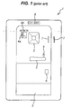
- a typical aircraft door 1 (in this case a door used on a Boeing 757 aircraft) includes a viewing window 2, an operating handle 3 for opening and locking the door 1 and a door mode select panel 4a, 4b for arming and disarming the door 1.
- a bustle 5 At the bottom of the door 1 is a bustle 5 in which an emergency evacuation slide (not shown) is stowed.
- a container of pressurised gas for inflating the slide in the event of an emergency.
- a pressure gauge 6 displays the pressure of the gas on the front of the door 1.
- a pair of handles 7 are provided towards the top and right of the door 1 which an operator can use to manoeuvre the door 1.
- the door mode select panel 4a, 4b comprises an operating switch 4a and a position indicator 4b.
- the position indicator 4b illustrates the direction in which the switch 4a need be switched to respectively arm and disarm the door 1.
- a slide placard 8 Just above the operating handle 3 is a slide placard 8.
- the slide placard When the door 1 is disarmed, the slide placard is retained in the body of the door 1, flush with the surface of the door 1.
- the switch 4a When the door 1 is armed by appropriate operation of the switch 4a, the slide placard is caused to pop out of the door and display an indicator that the door is armed.
- At the top of the door 1 is an LED 9 which is lit when the door 1 is armed and not lit when the door 1 is disarmed.
- LED 9 which is lit when the door 1 is armed and not lit when the door 1 is disarmed.
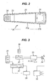
- FIG 2 shows the reverse side of a door operating handle 20 similar to that referenced 3 in Figure 1 .
- the handle has a substantially C shaped cross section made up of walls 21a, 21b and the front surface (not shown) of the handle 20.
- a taller walled section 21b is provided at one end of the handle to allow attachment to the front of a door whilst providing a clearance around the remainder of the handle 20 so that it may be gripped.
- an alarm system in accordance with the invention, 22, 23, 24, 25.
- Extending across a central portion of the handle is a pressure sensitive pad 22 enclosing an electrical circuit supplying the alarm system.
- Adjacent the pressure sensitive pad is an arming device 23 which is responsive to arming of an aircraft door to which the handle 20 is attached to arm the alarm system 22, 23, 24, 25.
- Adjacent the arming device 23 is a speaker 24 of an alarm sounder.
- the system is powered by a battery pack enclosed in a container 25.
- FIG 3 shows a circuit diagram for an alarm system substantially similar to the embodiment illustrated in Figure 2 .
- the circuit comprises a 9v dry power cell 31 which powers pressure sensor 37.
- the system is armed through arming device 32, 38 which comprises a Reed switch 32 and ceramic magnet 38.
- the ceramic magnet 38 is associated with a slide placard of an aircraft door, the Reed switch being positioned, in use, in close proximity to the placard and magnet 38.
- the slide placard pops out and the magnetic field near the magnetically sensitive Reed switch 32 is magnified. The change in the field is such as to cause the switch 32 to close.
- the alarm system circuit is now armed. Once the system is armed but not activated (i.e. there is no detection of pressure by sensor 37) a battery saver circuit 33 pulses a low current supply to LED 34 which emits an intermittent light, this provides a visual indicator that the system is armed and in a "stand by" mode.
- a latch circuit 36 is closed and the latch circuit 36 grabs power from the cell 31.
- the active latch circuit 36 triggers the broadcast of a timed, audible alarm, for example a pre-recorded voice message, through speaker/amplifier circuit 35.
- the senor is incorporated into an operating handle for the door.
- the electronic circuitry providing communication between the sensor and the arming means and aural alarm are located or are incorporated into the door structure.
- the senor is incorporated into, or located on, the door structure preferably just behind the handle.
- the sensor is close enough to the handle to sense when the handle is, or is about to be, touched by an operator.
Abstract
Description
- This invention relates to aircraft doors of the type typically used on passenger transport aircraft, in particular the invention relates to an alarm system for alerting cabin crew when a door is "armed".
- Doors of passenger transport aircraft are commonly fitted with inflatable slides to assist passenger evacuation in an emergency situation. Slides are typically stored in a bustle within the aircraft door. Such slides may be detachable from the aircraft to be used as life rafts. Prior to take off of an aircraft it is usual to "arm" the doors. This means a door is configured such that if it is opened, the emergency evacuation slide is released from the bustle. On release of the slide, gravity causes discharge of an associated gas pressurised cylinder which inflates the slide.
- Whilst such a feature is desirable in the event of an emergency evacuation of the aircraft, if the armed door is opened while the aircraft is stationed at an airport, inflation and deployment of the slide can cause injury to airport ground crew. Also, once a slide has been deployed, the door cannot be operable as an emergency exit until the slide has been replaced, a consequence being that the number of passengers which can be safely transported by the aircraft is reduced. It will also be appreciated that repackaging and replacement of a slide is time consuming and expensive and is desirably avoided.
- In order to avoid accidents or injury at airports, aircraft doors are fitted with one or more visual indicators of the status of the door, for example a door might include a light which displays in one colour when the door is armed and a different colour when the door is unarmed. Alternatively, a door might include a slidable or rotatable handle which can be moved between a position marked "ARMED" and a position marked "DISARMED" and/or a slide placard which displays when the door is armed and is hidden when the door is not armed.
- Whilst such indicators are generally effective, the inventors have recognised that in some circumstances a person might not register the indicator prior to acting to open the door. For example, the visual indicator may become obscured by another body, or a cabin crew member may be distracted when approaching the door and forget to check its status. As different aircraft have doors with different visual indicators, it is also conceivable that a cabin crew member operating on an aircraft of a type they have not previously encountered may misinterpret a visual indicator assuming a door to be disarmed when it is, in fact, armed.
- An alarm system activated by a touch-sensitive door knob is disclosed in
US 3,824,576 . In this patent rotation of the door knob retracts a latch bolt thus causing an electrical connection between the knob and the bolt thereby triggering an alarm. The system also provides a procedure whereby authorised personnel can enter the premises and deactivate the alarm system before the alarm is activated either through a time-delay circuit or through a separate de-activation means outside the building. -
GB-A-2 066 536 - It is an aim of the present invention to provide a novel aircraft door alarm system which alerts a door operator of the armed status of a door as the operator attempts to open the door.
- In accordance with a first aspect, the present invention provides an alarm system for an aircraft door comprising;
- a sensor for sensing when the door operating handle is about to be gripped by an operator,
- an aural alarm associated with the sensor and operable to sound when the sensor detects that the handle is about to be gripped,
- means for automatically arming the sensor and/or aural alarm when the emergency evacuation slide of the aircraft door is armed so as to be released if the aircraft door is opened
- The sensor may be a contactless type or alternatively may be a pressure sensor. As such, the term "about to be gripped" covers a situation where the sensor senses the hand of an operator prior to the handle being touched and a situation where the sensor senses pressure on the handle at the point where the handle is first touched.
- The system may be incorporated into an operating handle for the door or may be retrofittable to an existing door handle. Most conveniently, the sensor may comprise a pressure sensor located on or in the handle which sensor responds to hand pressure of an operator gripping the handle. Alternatively a sensor could be light, heat, humidity or chemically sensitive responding to contact with a characteristic of an operators hand.
- The aural alarm is desirably electrically operated. The sound made by the alarm may be one or more tones, optionally a repeating sequence of tones. Alternatively, the alarm may broadcast a pre-recorded voice message indicating that the door is armed.
- The arming means may be mechanically, electrically, optically or magnetically coupled to an existing means for arming the emergency evacuation slide of the door or an existing visual indicator for indicating the status of the door.
- In one option, the arming means may include a sensor which is activated following a change in the status of the door. For example, the sensor may be a light sensor obscurable by an operating switch or handle for arming the emergency evacuation slide of the door when the position of the switch or handle is changed. In another example, the arming means may include a magnetically sensitive switch such as a Reed switch which is responsive to a magnetic field which changes when the emergency evacuation slide of an aircraft door is switched between an armed and an unarmed configuration.
- The alarm system may include its own power source, for example but not strictly limited to a dry cell. Alternatively, the alarm system may tap power from an existing power source used to power the door and/or aircraft.
- Desirably, the alarm system includes its own indicator that it has been armed. Such an indicator may, for example, be a light emitting diode which lights or pulses when the system is armed.
- The system may be completely hard wired or may use one or more wireless connections between various of its components and/or existing components of the aircraft door. For example, there may be a blue tooth link between the sensor and alarm or between the means for activating the sensor and the sensor.
- In another aspect, the invention comprises a handle for an aircraft door incorporating the previously described alarm system.
- In yet another aspect, the invention comprises an aircraft door equipped with an alarm system as previously described.
- For the purposes of illustration, one embodiment of the invention will now be further described with reference to the following Figures in which:
-
Figure 1 illustrates the front face of an aircraft door as is known in the prior art. -
Figure 2 illustrates a handle for an aircraft door incorporating an embodiment of the alarm system of the invention. -
Figure 3 illustrates a circuit diagram for an embodiment of an alarm system in accordance with the invention. - As can be seen from
Figure 1 a typical aircraft door 1 (in this case a door used on a Boeing 757 aircraft) includes aviewing window 2, anoperating handle 3 for opening and locking the door 1 and a door modeselect panel bustle 5 in which an emergency evacuation slide (not shown) is stowed. Immediately above thebustle 5 is stowed a container of pressurised gas for inflating the slide in the event of an emergency. Apressure gauge 6 displays the pressure of the gas on the front of the door 1. A pair ofhandles 7 are provided towards the top and right of the door 1 which an operator can use to manoeuvre the door 1. - The door mode
select panel operating switch 4a and aposition indicator 4b. Theposition indicator 4b illustrates the direction in which theswitch 4a need be switched to respectively arm and disarm the door 1. Just above theoperating handle 3 is aslide placard 8. When the door 1 is disarmed, the slide placard is retained in the body of the door 1, flush with the surface of the door 1. When the door 1 is armed by appropriate operation of theswitch 4a, the slide placard is caused to pop out of the door and display an indicator that the door is armed. At the top of the door 1 is anLED 9 which is lit when the door 1 is armed and not lit when the door 1 is disarmed. Thus there are three visual indicators (LED 9,slide placard 8 anddisplay panel -
Figure 2 shows the reverse side of adoor operating handle 20 similar to that referenced 3 inFigure 1 . The handle has a substantially C shaped cross section made up ofwalls handle 20. A taller walledsection 21b is provided at one end of the handle to allow attachment to the front of a door whilst providing a clearance around the remainder of thehandle 20 so that it may be gripped. - Enclosed within the C section is an alarm system in accordance with the invention, 22, 23, 24, 25. Extending across a central portion of the handle is a pressure
sensitive pad 22 enclosing an electrical circuit supplying the alarm system. Adjacent the pressure sensitive pad is an armingdevice 23 which is responsive to arming of an aircraft door to which thehandle 20 is attached to arm thealarm system - Adjacent the arming
device 23 is aspeaker 24 of an alarm sounder. The system is powered by a battery pack enclosed in acontainer 25. - It will be appreciated that the components of the system as described in relation to
Figure 2 could be re-ordered without affecting the mode of operation of the invention. -
Figure 3 shows a circuit diagram for an alarm system substantially similar to the embodiment illustrated inFigure 2 . The circuit comprises a 9vdry power cell 31 which powerspressure sensor 37. - The system is armed through arming
device Reed switch 32 andceramic magnet 38. Theceramic magnet 38 is associated with a slide placard of an aircraft door, the Reed switch being positioned, in use, in close proximity to the placard andmagnet 38. When a door to which the system is mounted is armed, the slide placard pops out and the magnetic field near the magneticallysensitive Reed switch 32 is magnified. The change in the field is such as to cause theswitch 32 to close. The alarm system circuit is now armed. Once the system is armed but not activated (i.e. there is no detection of pressure by sensor 37) abattery saver circuit 33 pulses a low current supply toLED 34 which emits an intermittent light, this provides a visual indicator that the system is armed and in a "stand by" mode. - When the
pressure sensor 37 is subjected to pressure, for example when the door handle is gripped, a sub circuit including thepressure sensor 37 andLED 34 is closed and the LED becomes permanently lit, taking current directly from thedry cell 31 indicating the alarm has been activated. - Simultaneously, a
latch circuit 36 is closed and thelatch circuit 36 grabs power from thecell 31. Theactive latch circuit 36 triggers the broadcast of a timed, audible alarm, for example a pre-recorded voice message, through speaker/amplifier circuit 35. - Once the
pressure sensor 37 is relieved of pressure, the supply conduits between thesensor 31 and each of thelatch circuit 36 andLED 34 are closed, the alarm stops sounding and the LED reverts to blinking. Once the door is disarmed, the slide placard reverts to the "disarmed" position withdrawing themagnet 38 from theReed switch 32 causing theswitch 32 to open. The alarm system is then disarmed and the door can be operated without setting off the aural alarm. - In an alternative embodiment (not shown) only the sensor is incorporated into an operating handle for the door. The electronic circuitry providing communication between the sensor and the arming means and aural alarm are located or are incorporated into the door structure.
- In a further alternative embodiment (also not shown) the sensor is incorporated into, or located on, the door structure preferably just behind the handle. The sensor is close enough to the handle to sense when the handle is, or is about to be, touched by an operator.
- It is to be understood that the forgoing is merely representative of one embodiment which the alarm system of the invention may take, other embodiments will no doubt occur to the skilled addressee without the need for inventive thought and without departing from the scope of the invention as claimed in the appended claims.
Claims (27)
- An alarm system for an aircraft door (1) comprising;a sensor (37) for sensing when the door operating handle (20) is about to be gripped by an operator,an aural alarm (35) associated with the sensor (37) and operable to sound when the sensor (37) detects that the handle (20) is about to be gripped, andmeans for automatically arming the sensor and/or aural alarm (32) when the emergency evacuation slide of the aircraft door (1) is armed so as to be released if the air craft door (1) is opened.
- An alarm system as claimed in claim 1, wherein the aural alarm (35) and the means for arming the sensor and/or activating the aural alarm (32) are embodied in the aircraft door (1).
- An alarm system as claimed in claim 1 or claim 2 wherein the sensor (37) is incorporated in, or located on, the door operating handle (20).
- An alarm system as claimed in claim 1 or claim 2, wherein the sensor (37) is incorporated into, or otherwise located on, the aircraft door (1) within the immediate vicinity of the door operating handle (20).
- An alarm system as claimed in claim 1 which is embodied in a door operating handle (20) for an aircraft door (1).
- An alarm system as claimed in any one of claims 1 to 5 wherein the sensor (37) comprises a pressure sensor.
- An alarm system as claimed in any one of claims 1 to 5 wherein the sensor (37) is a light sensor.
- An alarm system as claimed in any preceding claim wherein the aural alarm (35) is electrically operated.
- An alarm system as claimed in claim 8 wherein the aural alarm (35) sounds one or more tones.
- An alarm system as claimed in claim 9 wherein the aural alarm (35) sounds a repeating sequence of tones.
- An alarm system as claimed in claim 8 wherein the aurall alarm (35) sounds a pre-recorded voice message in one or more languages.
- An alarm system as claimed in claim 1 wherein the arming means (32) is mechanically, electrically, optically or magnetically couplable to an existing means for arming the emergency evacuation slide of an aircraft door (4A) or an existing visual indicator (8, 9) for indicating the status of the aircraft door (1).
- An alarm system as claimed in claim 12 wherein the arming means (32) includes a sensor which is activated following a change in the status of the door (1).
- An alarm system as claimed in claim 13 wherein the arming means sensor is a light sensor obscurable by an operating switch (4A) or handle for arming the door (1) when the position of the switch (4A) or handle is changed.
- An alarm system as claimed in claim 13 wherein the arming means (32) includes a magnetically sensitive switch (32, 38) which is responsive to a magnetic field which changes when the emergency evacuation slide of an aircraft door (1) to which it is attachable is switched between an armed and an unarmed configuration.
- An alarm system as claimed in claim 15 wherein the changing magnetic field is associated with a slide placard (8) of an aircraft door (1) to which the alarm system is attachable.
- An alarm system as claimed in any preceding claim including its own power source (31).
- An alarm system as claimed in claim 17 wherein the power source is a dry cell (31).
- An alarm system as claimed in any of claims 1 to 16 wherein the alarm system is configured to tap power from an existing power supply of an aircraft door (1) or aircraft to which it is attachable.
- An alarm system as claimed in any of the preceding claims wherein the alarm system includes its own indicator (34) that the system has been armed.
- An alarm system as claimed in claim 20 wherein the arming system indicator is a light emitting diode (34) which lights or pulses when the system is armed and ceases when the system is not armed.
- An alarm system as claimed in any preceding claim wherein the system is hard wired.
- An alarm system as claimed in any of claims 1 to 21 wherein the system includes one or more wireless connections between various of its components and/or existing components of an aircraft door (1) to which it may be attached.
- An alarm system as claimed in claim 23 wherein a blue tooth link is provided between the sensor and alarm or between the means for arming the sensor and the sensor.
- An operating handle (20) for an aircraft door incorporating the alarm system of any preceding claim.
- An operating handle as claimed in claim 25 wherein the handle (20) is substantially C shaped in cross section and one or more of the components of the alarm system are mounted in the C of the C shaped cross section.
- An aircraft door (1) incorporating an operating handle (20) as claimed in claim 25 or claim 26.
Applications Claiming Priority (2)
| Application Number | Priority Date | Filing Date | Title |
|---|---|---|---|
| GB0404328A GB2416616A (en) | 2004-02-27 | 2004-02-27 | Aircraft door handle alarm |
| PCT/GB2005/000607 WO2005083647A1 (en) | 2004-02-27 | 2005-02-21 | Improvements in aircraft doors |
Publications (2)
| Publication Number | Publication Date |
|---|---|
| EP1719084A1 EP1719084A1 (en) | 2006-11-08 |
| EP1719084B1 true EP1719084B1 (en) | 2011-01-12 |
Family
ID=32050940
Family Applications (1)
| Application Number | Title | Priority Date | Filing Date |
|---|---|---|---|
| EP05717752A Active EP1719084B1 (en) | 2004-02-27 | 2005-02-21 | Improvements in aircraft doors |
Country Status (12)
| Country | Link |
|---|---|
| US (1) | US8121438B2 (en) |
| EP (1) | EP1719084B1 (en) |
| JP (1) | JP4589378B2 (en) |
| CN (1) | CN100543789C (en) |
| AT (1) | ATE495514T1 (en) |
| BR (1) | BRPI0508042A (en) |
| CA (1) | CA2557512C (en) |
| DE (1) | DE602005006752D1 (en) |
| ES (1) | ES2358909T3 (en) |
| GB (1) | GB2416616A (en) |
| RU (1) | RU2383930C2 (en) |
| WO (1) | WO2005083647A1 (en) |
Cited By (4)
| Publication number | Priority date | Publication date | Assignee | Title |
|---|---|---|---|---|
| DE102011086454A1 (en) | 2011-11-16 | 2013-05-16 | Airbus Operations Gmbh | Monitoring device and method for monitoring a movement profile of a user in the area of an actuating element of an aircraft or spacecraft |
| EP2974963A1 (en) | 2014-07-18 | 2016-01-20 | Airbus Operations GmbH | Apparatus for operating a door of an aircraft, an aircraft having such an apparatus and method for operating a door of an aircraft |
| US9789970B2 (en) | 2008-04-07 | 2017-10-17 | Airbus Operations Gmbh | System and method for prevention of inadvertent escape slide deployment for an aircraft |
| DE102019107823A1 (en) * | 2019-03-27 | 2020-10-01 | Airbus Operations Gmbh | Cabin door system for an aircraft and an aircraft with at least one such cabin door system |
Families Citing this family (12)
| Publication number | Priority date | Publication date | Assignee | Title |
|---|---|---|---|---|
| GB2416616A (en) * | 2004-02-27 | 2006-02-01 | Christopher Yardley | Aircraft door handle alarm |
| GB2425638B (en) * | 2005-04-28 | 2010-06-30 | Christopher Yardley | Aircraft door handle alarm system |
| DE102005060425B4 (en) * | 2005-12-15 | 2013-03-28 | Primion Technology Ag | Door actuator |
| US9809313B2 (en) | 2007-01-22 | 2017-11-07 | Honeywell International Inc. | Cabin altitude alerting systems and methods |
| US8686877B2 (en) * | 2012-06-26 | 2014-04-01 | The Boeing Company | Directionally filtered indicator light |
| EP2878530B1 (en) * | 2013-11-27 | 2019-02-27 | Airbus Operations GmbH | Warning circuitry and warning device for an aircraft |
| GB2524847A (en) * | 2014-04-06 | 2015-10-07 | Peter John Charles Spurgeon | A door entry device |
| DE102015100880A1 (en) * | 2015-01-21 | 2016-07-21 | Airbus Operations Gmbh | Retrofittable display device for indicating an activation status of an escape slide in an aircraft |
| EP3439961A1 (en) * | 2016-04-05 | 2019-02-13 | Airbus Operations GmbH | Retrofittable display device for displaying an activation status of an emergency chute in an aircraft |
| IT201600101548A1 (en) * | 2016-10-12 | 2018-04-12 | Romualdo Cozza | Warning signaling and activation device and remember for everyday objects such as keys and wallet |
| RU184400U9 (en) * | 2018-06-19 | 2018-12-07 | Акционерное общество "ЦентрИнформ" | ELECTRONIC RADIO FREQUENCY SEAL |
| US11745880B2 (en) | 2020-01-17 | 2023-09-05 | Goodrich Corporation | Readiness indicator lights for evacuation slide |
Family Cites Families (27)
| Publication number | Priority date | Publication date | Assignee | Title |
|---|---|---|---|---|
| US3824576A (en) * | 1972-08-16 | 1974-07-16 | R Pioch | Alarm system activated by touch sensitive door knob intrusior |
| GB2066536B (en) | 1979-01-04 | 1982-12-15 | Bajius T | Alarm device |
| US4389647A (en) * | 1980-12-22 | 1983-06-21 | The United States Of America As Represented By The Secretary Of The Army | Doppler discrimination of aircraft targets |
| US5075694A (en) * | 1987-05-18 | 1991-12-24 | Avion Systems, Inc. | Airborne surveillance method and system |
| US5407149A (en) * | 1991-05-30 | 1995-04-18 | Singhai; Tara C. | Devices and means to engage in indoor flight of radio controlled model aircrafts |
| IL104542A (en) * | 1993-01-28 | 1996-05-14 | Israel State | Airborne obstacle collision avoidance apparatus |
| US5521584A (en) * | 1993-10-13 | 1996-05-28 | Eaton Corporation | Apparatus and method for detecting ice |
| JP3196805B2 (en) | 1995-02-14 | 2001-08-06 | 日本電信電話株式会社 | Display device and portable electronic device |
| US5724040A (en) * | 1995-06-23 | 1998-03-03 | Northrop Grumman Corporation | Aircraft wake vortex hazard warning apparatus |
| US5557278A (en) * | 1995-06-23 | 1996-09-17 | Northrop Grumman Corporation | Airport integrated hazard response apparatus |
| US5793881A (en) * | 1995-08-31 | 1998-08-11 | Stiver; John A. | Identification system |
| US5781146A (en) * | 1996-03-11 | 1998-07-14 | Imaging Accessories, Inc. | Automatic horizontal and vertical scanning radar with terrain display |
| JPH10206969A (en) | 1997-01-24 | 1998-08-07 | Ricoh Co Ltd | Image display device and attachment for image display device |
| JPH10293268A (en) | 1997-04-17 | 1998-11-04 | Sony Corp | Laser display device |
| US6154151A (en) * | 1998-06-16 | 2000-11-28 | Rockwell Collins, Inc. | Integrated vertical situation display for aircraft |
| DE19843594C2 (en) * | 1998-09-23 | 2001-03-08 | Valeo Gmbh & Co Schliessyst Kg | Door handle |
| DE19924948A1 (en) * | 1999-05-31 | 2002-09-19 | Dieter Wittchow | Device for indicating motor vehicle break-in, has sensor or mechanical switch mounted on door handle |
| DE19943040A1 (en) | 1999-09-09 | 2001-03-15 | Geze Gmbh | Building exit device has one or more components, e.g. monitor and alarm, mounted in free-standing housing at distance from door or window |
| JP2002341280A (en) | 2001-05-16 | 2002-11-27 | Canon Inc | Projection type display device and light beam projection preventing method for the same device |
| JP2003029201A (en) | 2001-07-11 | 2003-01-29 | Canon Inc | Picture projecting device and picture correcting method |
| JP2003029343A (en) | 2001-07-13 | 2003-01-29 | Olympus Optical Co Ltd | Secret image display |
| JP2003101909A (en) | 2001-09-25 | 2003-04-04 | Matsushita Electric Ind Co Ltd | Portable electronic equipment and image display device |
| US6819264B2 (en) * | 2002-01-14 | 2004-11-16 | Richard L. Bissett | Cabin situation alert system |
| US6577429B1 (en) | 2002-01-15 | 2003-06-10 | Eastman Kodak Company | Laser projection display system |
| KR100459899B1 (en) | 2002-03-12 | 2004-12-04 | 삼성전자주식회사 | Laser video projector having multi-channel acoustic optic modulator, method and circuit of driving the same |
| FR2840096B1 (en) * | 2002-05-23 | 2006-06-30 | Airbus | LIGHTNING ALERT DEVICE AND INDICATING A RELIEF OUTCOME |
| GB2416616A (en) * | 2004-02-27 | 2006-02-01 | Christopher Yardley | Aircraft door handle alarm |
-
2004
- 2004-02-27 GB GB0404328A patent/GB2416616A/en not_active Withdrawn
-
2005
- 2005-02-12 CN CNB2005800110937A patent/CN100543789C/en not_active Expired - Fee Related
- 2005-02-12 US US10/590,890 patent/US8121438B2/en not_active Expired - Fee Related
- 2005-02-21 EP EP05717752A patent/EP1719084B1/en active Active
- 2005-02-21 DE DE602005006752T patent/DE602005006752D1/en active Active
- 2005-02-21 JP JP2007500279A patent/JP4589378B2/en not_active Expired - Fee Related
- 2005-02-21 RU RU2006134278/09A patent/RU2383930C2/en not_active IP Right Cessation
- 2005-02-21 ES ES05717752T patent/ES2358909T3/en active Active
- 2005-02-21 AT AT05717752T patent/ATE495514T1/en not_active IP Right Cessation
- 2005-02-21 WO PCT/GB2005/000607 patent/WO2005083647A1/en active Application Filing
- 2005-02-21 BR BRPI0508042-8A patent/BRPI0508042A/en not_active IP Right Cessation
- 2005-02-21 CA CA2557512A patent/CA2557512C/en not_active Expired - Fee Related
Cited By (9)
| Publication number | Priority date | Publication date | Assignee | Title |
|---|---|---|---|---|
| US9789970B2 (en) | 2008-04-07 | 2017-10-17 | Airbus Operations Gmbh | System and method for prevention of inadvertent escape slide deployment for an aircraft |
| DE102011086454A1 (en) | 2011-11-16 | 2013-05-16 | Airbus Operations Gmbh | Monitoring device and method for monitoring a movement profile of a user in the area of an actuating element of an aircraft or spacecraft |
| WO2013072334A2 (en) | 2011-11-16 | 2013-05-23 | Airbus Operations Gmbh | Monitoring device and method for monitoring a movement profile of a user in the region of an actuating element of an aircraft or spacecraft |
| EP2974963A1 (en) | 2014-07-18 | 2016-01-20 | Airbus Operations GmbH | Apparatus for operating a door of an aircraft, an aircraft having such an apparatus and method for operating a door of an aircraft |
| US9870691B2 (en) | 2014-07-18 | 2018-01-16 | Airbus Operations Gmbh | Apparatus for operating a door of an aircraft, an aircraft having such an apparatus and method for operating a door of an aircraft |
| DE102019107823A1 (en) * | 2019-03-27 | 2020-10-01 | Airbus Operations Gmbh | Cabin door system for an aircraft and an aircraft with at least one such cabin door system |
| GB2587688A (en) | 2019-03-27 | 2021-04-07 | Airbus Operations Gmbh | Cabin door system for an aircraft and an aircraft having at least one such cabin door system |
| GB2587688B (en) * | 2019-03-27 | 2022-11-23 | Airbus Operations Gmbh | Cabin door system for an aircraft and an aircraft having at least one such cabin door system |
| US11591062B2 (en) | 2019-03-27 | 2023-02-28 | Airbus Operations Gmbh | Cabin door system for an aircraft and an aircraft having at least one such cabin door system |
Also Published As
| Publication number | Publication date |
|---|---|
| US20080284619A1 (en) | 2008-11-20 |
| ATE495514T1 (en) | 2011-01-15 |
| GB0404328D0 (en) | 2004-03-31 |
| CA2557512C (en) | 2014-01-21 |
| CN1942907A (en) | 2007-04-04 |
| JP4589378B2 (en) | 2010-12-01 |
| US8121438B2 (en) | 2012-02-21 |
| WO2005083647A1 (en) | 2005-09-09 |
| CN100543789C (en) | 2009-09-23 |
| DE602005006752D1 (en) | 2011-05-05 |
| JP2007524546A (en) | 2007-08-30 |
| RU2383930C2 (en) | 2010-03-10 |
| ES2358909T3 (en) | 2011-05-16 |
| CA2557512A1 (en) | 2005-09-09 |
| BRPI0508042A (en) | 2007-07-17 |
| EP1719084A1 (en) | 2006-11-08 |
| RU2006134278A (en) | 2008-04-20 |
| WO2005083647A8 (en) | 2007-04-19 |
| GB2416616A (en) | 2006-02-01 |
Similar Documents
| Publication | Publication Date | Title |
|---|---|---|
| EP1719084B1 (en) | Improvements in aircraft doors | |
| EP2108585B1 (en) | System and method for prevention of inadvertent escape slide deployment for an aircraft | |
| EP1877309B1 (en) | Improvements in aircraft doors | |
| ES2360076T3 (en) | AIRCRAFT WITH CABIN DIFFERENTIAL PRESSURE ALERT SYSTEM. | |
| EP2878530B1 (en) | Warning circuitry and warning device for an aircraft | |
| US20030136009A1 (en) | Insitu apparatus and method for breaking glass | |
| US7113109B2 (en) | Voice activated alerting system for aircraft crew | |
| US10329001B2 (en) | Distress device of lifejacket | |
| US7125298B1 (en) | Man overboard beacon | |
| US20050073442A1 (en) | Skier alert system with fallen skier alarm | |
| TWM551145U (en) | Information notification device for vehicle | |
| US10822115B2 (en) | Retrofittable display device for displaying an activation status of an emergency chute in an aircraft | |
| CN205959352U (en) | System for a slide expandes for preventing due to carelessness | |
| CN111746779A (en) | Aircraft cabin door system and aircraft with at least one such cabin door system | |
| CN219626128U (en) | Road rescue safety precaution device | |
| US11568752B2 (en) | Gateway retrieval alert device for aircraft pushback operations | |
| CN208477679U (en) | Electric locomotive wireless distance finding prior-warning device | |
| KR20210013829A (en) | Emergency signaling device for vehicles | |
| WO1995012869A1 (en) | Warning device | |
| WO2007084123A2 (en) | Voice activated alerting system for aircraft crew | |
| JPH11161864A (en) | Emergency lifesaving annunciator | |
| ITRM20000046U1 (en) | INFLATABLE OR FLAMMABLE RESCUE JACKET FOR INTERIOR FLOATING, FOR AERONAUTICAL AND NAUTICAL USE, VISIBLE TO RADARS AND OR |
Legal Events
| Date | Code | Title | Description |
|---|---|---|---|
| PUAI | Public reference made under article 153(3) epc to a published international application that has entered the european phase |
Free format text: ORIGINAL CODE: 0009012 |
|
| 17P | Request for examination filed |
Effective date: 20060920 |
|
| AK | Designated contracting states |
Kind code of ref document: A1 Designated state(s): AT BE BG CH CY CZ DE DK EE ES FI FR GB GR HU IE IS IT LI LT LU MC NL PL PT RO SE SI SK TR |
|
| AX | Request for extension of the european patent |
Extension state: AL BA HR LV MK YU |
|
| RAP1 | Party data changed (applicant data changed or rights of an application transferred) |
Owner name: FARMER, MICHAEL JOHN CHARLES Owner name: YARDLEY, CHRISTOPHER |
|
| RIN1 | Information on inventor provided before grant (corrected) |
Inventor name: FARMER, MICHAEL JOHN CHARLES Inventor name: YARDLEY, CHRISTOPHER |
|
| D17D | Deferred search report published (deleted) | ||
| GRAP | Despatch of communication of intention to grant a patent |
Free format text: ORIGINAL CODE: EPIDOSNIGR1 |
|
| REG | Reference to a national code |
Ref country code: GB Ref legal event code: 712B Free format text: REQUEST BY JOINT APPLICANTS FOR DIRECTIONS UNDER SECTION 12(4) FILED ON 20071207 Ref country code: GB Ref legal event code: 712F |
|
| GRAS | Grant fee paid |
Free format text: ORIGINAL CODE: EPIDOSNIGR3 |
|
| GRAA | (expected) grant |
Free format text: ORIGINAL CODE: 0009210 |
|
| AK | Designated contracting states |
Kind code of ref document: B1 Designated state(s): AT BE BG CH CY CZ DE DK EE ES FI FR GB GR HU IE IS IT LI LT LU MC NL PL PT RO SE SI SK TR |
|
| AX | Request for extension of the european patent |
Extension state: AL BA HR LV MK YU |
|
| REG | Reference to a national code |
Ref country code: GB Ref legal event code: FG4D |
|
| PUAC | Information related to the publication of a b1 document modified or deleted |
Free format text: ORIGINAL CODE: 0009299EPPU |
|
| REG | Reference to a national code |
Ref country code: CH Ref legal event code: EP |
|
| REG | Reference to a national code |
Ref country code: IE Ref legal event code: FG4D Free format text: LANGUAGE OF EP DOCUMENT: FRENCH |
|
| REG | Reference to a national code |
Ref country code: CH Ref legal event code: PK Free format text: BERICHTIGUNG |
|
| REF | Corresponds to: |
Ref document number: 602005006752 Country of ref document: DE Date of ref document: 20080626 Kind code of ref document: P |
|
| DB1 | Publication of patent cancelled | ||
| REG | Reference to a national code |
Ref country code: GB Ref legal event code: S12A Free format text: REQUEST WITHDRAWN Effective date: 20080613 Ref country code: GB Ref legal event code: S12D Free format text: REQUEST WITHDRAWN Effective date: 20080613 |
|
| NLXE | Nl: other communications concerning ep-patents (part 3 heading xe) |
Free format text: PAT. BUL. 07/2008 PATENTNUMBER 1719084 SHOULD BE DELETED (SEE EUROPEAN PATENT BULLETIN 20080702) |
|
| REG | Reference to a national code |
Ref country code: FR Ref legal event code: ST Effective date: 20091030 |
|
| 19F | Resumption of proceedings before grant (after stay of proceedings) |
Effective date: 20100901 |
|
| RAP1 | Party data changed (applicant data changed or rights of an application transferred) |
Owner name: PENNY & GILES AEROSPACE LIMITED |
|
| RIN1 | Information on inventor provided before grant (corrected) |
Inventor name: FARMER, MICHAEL JOHN CHARLES Inventor name: YARDLEY CHRISTOPHER |
|
| GRAA | (expected) grant |
Free format text: ORIGINAL CODE: 0009210 |
|
| AK | Designated contracting states |
Kind code of ref document: B1 Designated state(s): AT BE BG CH CY CZ DE DK EE ES FI FR GB GR HU IE IS IT LI LT LU MC NL PL PT RO SE SI SK TR |
|
| AX | Request for extension of the european patent |
Extension state: AL BA HR LV MK YU |
|
| REG | Reference to a national code |
Ref country code: GB Ref legal event code: FG4D |
|
| REG | Reference to a national code |
Ref country code: CH Ref legal event code: EP Ref country code: CH Ref legal event code: PK Free format text: DIE ERTEILUNG VOM 14.05.2008 WURDE VOM EPA WIDERRUFEN |
|
| REF | Corresponds to: |
Ref document number: 602005006752 Country of ref document: DE Date of ref document: 20110505 Kind code of ref document: P |
|
| REG | Reference to a national code |
Ref country code: DE Ref legal event code: R096 Ref document number: 602005006752 Country of ref document: DE Effective date: 20110505 |
|
| REG | Reference to a national code |
Ref country code: ES Ref legal event code: FG2A Ref document number: 2358909 Country of ref document: ES Kind code of ref document: T3 Effective date: 20110504 |
|
| REG | Reference to a national code |
Ref country code: NL Ref legal event code: VDEP Effective date: 20110112 |
|
| LTIE | Lt: invalidation of european patent or patent extension |
Effective date: 20110112 |
|
| REG | Reference to a national code |
Ref country code: ES Ref legal event code: FD2A Effective date: 20110711 |
|
| PG25 | Lapsed in a contracting state [announced via postgrant information from national office to epo] |
Ref country code: LT Free format text: LAPSE BECAUSE OF FAILURE TO SUBMIT A TRANSLATION OF THE DESCRIPTION OR TO PAY THE FEE WITHIN THE PRESCRIBED TIME-LIMIT Effective date: 20110112 Ref country code: ES Free format text: LAPSE BECAUSE OF NON-PAYMENT OF DUE FEES Effective date: 20110629 |
|
| PG25 | Lapsed in a contracting state [announced via postgrant information from national office to epo] |
Ref country code: AT Free format text: LAPSE BECAUSE OF FAILURE TO SUBMIT A TRANSLATION OF THE DESCRIPTION OR TO PAY THE FEE WITHIN THE PRESCRIBED TIME-LIMIT Effective date: 20110112 Ref country code: FI Free format text: LAPSE BECAUSE OF FAILURE TO SUBMIT A TRANSLATION OF THE DESCRIPTION OR TO PAY THE FEE WITHIN THE PRESCRIBED TIME-LIMIT Effective date: 20110112 Ref country code: SI Free format text: LAPSE BECAUSE OF FAILURE TO SUBMIT A TRANSLATION OF THE DESCRIPTION OR TO PAY THE FEE WITHIN THE PRESCRIBED TIME-LIMIT Effective date: 20110112 Ref country code: NL Free format text: LAPSE BECAUSE OF FAILURE TO SUBMIT A TRANSLATION OF THE DESCRIPTION OR TO PAY THE FEE WITHIN THE PRESCRIBED TIME-LIMIT Effective date: 20110112 |
|
| PG25 | Lapsed in a contracting state [announced via postgrant information from national office to epo] |
Ref country code: MC Free format text: LAPSE BECAUSE OF NON-PAYMENT OF DUE FEES Effective date: 20110228 |
|
| REG | Reference to a national code |
Ref country code: CH Ref legal event code: PL |
|
| PG25 | Lapsed in a contracting state [announced via postgrant information from national office to epo] |
Ref country code: LI Free format text: LAPSE BECAUSE OF NON-PAYMENT OF DUE FEES Effective date: 20110228 Ref country code: EE Free format text: LAPSE BECAUSE OF FAILURE TO SUBMIT A TRANSLATION OF THE DESCRIPTION OR TO PAY THE FEE WITHIN THE PRESCRIBED TIME-LIMIT Effective date: 20110112 Ref country code: DK Free format text: LAPSE BECAUSE OF FAILURE TO SUBMIT A TRANSLATION OF THE DESCRIPTION OR TO PAY THE FEE WITHIN THE PRESCRIBED TIME-LIMIT Effective date: 20110112 Ref country code: CH Free format text: LAPSE BECAUSE OF NON-PAYMENT OF DUE FEES Effective date: 20110228 |
|
| REG | Reference to a national code |
Ref country code: ES Ref legal event code: FD2A Effective date: 20111116 |
|
| PLBE | No opposition filed within time limit |
Free format text: ORIGINAL CODE: 0009261 |
|
| STAA | Information on the status of an ep patent application or granted ep patent |
Free format text: STATUS: NO OPPOSITION FILED WITHIN TIME LIMIT |
|
| REG | Reference to a national code |
Ref country code: IE Ref legal event code: MM4A |
|
| PG25 | Lapsed in a contracting state [announced via postgrant information from national office to epo] |
Ref country code: CZ Free format text: LAPSE BECAUSE OF FAILURE TO SUBMIT A TRANSLATION OF THE DESCRIPTION OR TO PAY THE FEE WITHIN THE PRESCRIBED TIME-LIMIT Effective date: 20110112 Ref country code: SK Free format text: LAPSE BECAUSE OF FAILURE TO SUBMIT A TRANSLATION OF THE DESCRIPTION OR TO PAY THE FEE WITHIN THE PRESCRIBED TIME-LIMIT Effective date: 20110112 |
|
| 26N | No opposition filed |
Effective date: 20111013 |
|
| PG25 | Lapsed in a contracting state [announced via postgrant information from national office to epo] |
Ref country code: IE Free format text: LAPSE BECAUSE OF NON-PAYMENT OF DUE FEES Effective date: 20110221 |
|
| REG | Reference to a national code |
Ref country code: DE Ref legal event code: R097 Ref document number: 602005006752 Country of ref document: DE Effective date: 20111013 |
|
| PG25 | Lapsed in a contracting state [announced via postgrant information from national office to epo] |
Ref country code: CY Free format text: LAPSE BECAUSE OF FAILURE TO SUBMIT A TRANSLATION OF THE DESCRIPTION OR TO PAY THE FEE WITHIN THE PRESCRIBED TIME-LIMIT Effective date: 20110112 Ref country code: LU Free format text: LAPSE BECAUSE OF NON-PAYMENT OF DUE FEES Effective date: 20110112 |
|
| PG25 | Lapsed in a contracting state [announced via postgrant information from national office to epo] |
Ref country code: IS Free format text: LAPSE BECAUSE OF FAILURE TO SUBMIT A TRANSLATION OF THE DESCRIPTION OR TO PAY THE FEE WITHIN THE PRESCRIBED TIME-LIMIT Effective date: 20110112 Ref country code: PT Free format text: LAPSE BECAUSE OF NON-PAYMENT OF DUE FEES Effective date: 20110112 Ref country code: SE Free format text: LAPSE BECAUSE OF FAILURE TO SUBMIT A TRANSLATION OF THE DESCRIPTION OR TO PAY THE FEE WITHIN THE PRESCRIBED TIME-LIMIT Effective date: 20110112 |
|
| PG25 | Lapsed in a contracting state [announced via postgrant information from national office to epo] |
Ref country code: PL Free format text: LAPSE BECAUSE OF NON-PAYMENT OF DUE FEES Effective date: 20110112 |
|
| PG25 | Lapsed in a contracting state [announced via postgrant information from national office to epo] |
Ref country code: TR Free format text: LAPSE BECAUSE OF FAILURE TO SUBMIT A TRANSLATION OF THE DESCRIPTION OR TO PAY THE FEE WITHIN THE PRESCRIBED TIME-LIMIT Effective date: 20110112 |
|
| PG25 | Lapsed in a contracting state [announced via postgrant information from national office to epo] |
Ref country code: HU Free format text: LAPSE BECAUSE OF FAILURE TO SUBMIT A TRANSLATION OF THE DESCRIPTION OR TO PAY THE FEE WITHIN THE PRESCRIBED TIME-LIMIT Effective date: 20110112 |
|
| PGFP | Annual fee paid to national office [announced via postgrant information from national office to epo] |
Ref country code: DE Payment date: 20140220 Year of fee payment: 10 |
|
| PGFP | Annual fee paid to national office [announced via postgrant information from national office to epo] |
Ref country code: ES Payment date: 20140221 Year of fee payment: 10 Ref country code: IT Payment date: 20140225 Year of fee payment: 10 |
|
| PGFP | Annual fee paid to national office [announced via postgrant information from national office to epo] |
Ref country code: GB Payment date: 20140226 Year of fee payment: 10 |
|
| PG25 | Lapsed in a contracting state [announced via postgrant information from national office to epo] |
Ref country code: RO Free format text: LAPSE BECAUSE OF FAILURE TO SUBMIT A TRANSLATION OF THE DESCRIPTION OR TO PAY THE FEE WITHIN THE PRESCRIBED TIME-LIMIT Effective date: 20110112 |
|
| PG25 | Lapsed in a contracting state [announced via postgrant information from national office to epo] |
Ref country code: GR Free format text: LAPSE BECAUSE OF FAILURE TO SUBMIT A TRANSLATION OF THE DESCRIPTION OR TO PAY THE FEE WITHIN THE PRESCRIBED TIME-LIMIT Effective date: 20110112 Ref country code: BG Free format text: LAPSE BECAUSE OF NON-PAYMENT OF DUE FEES Effective date: 20110112 |
|
| PGFP | Annual fee paid to national office [announced via postgrant information from national office to epo] |
Ref country code: FR Payment date: 20140227 Year of fee payment: 10 |
|
| PG25 | Lapsed in a contracting state [announced via postgrant information from national office to epo] |
Ref country code: BE Free format text: LAPSE BECAUSE OF NON-PAYMENT OF DUE FEES Effective date: 20110112 |
|
| REG | Reference to a national code |
Ref country code: DE Ref legal event code: R119 Ref document number: 602005006752 Country of ref document: DE |
|
| GBPC | Gb: european patent ceased through non-payment of renewal fee |
Effective date: 20150221 |
|
| REG | Reference to a national code |
Ref country code: FR Ref legal event code: ST Effective date: 20151030 |
|
| PG25 | Lapsed in a contracting state [announced via postgrant information from national office to epo] |
Ref country code: IT Free format text: LAPSE BECAUSE OF NON-PAYMENT OF DUE FEES Effective date: 20150221 |
|
| PG25 | Lapsed in a contracting state [announced via postgrant information from national office to epo] |
Ref country code: DE Free format text: LAPSE BECAUSE OF NON-PAYMENT OF DUE FEES Effective date: 20150901 Ref country code: GB Free format text: LAPSE BECAUSE OF NON-PAYMENT OF DUE FEES Effective date: 20150221 |
|
| PG25 | Lapsed in a contracting state [announced via postgrant information from national office to epo] |
Ref country code: FR Free format text: LAPSE BECAUSE OF NON-PAYMENT OF DUE FEES Effective date: 20150302 |
|
| REG | Reference to a national code |
Ref country code: ES Ref legal event code: FD2A Effective date: 20160329 |
|
| PG25 | Lapsed in a contracting state [announced via postgrant information from national office to epo] |
Ref country code: ES Free format text: LAPSE BECAUSE OF NON-PAYMENT OF DUE FEES Effective date: 20150222 |