EP1662276B1 - Lentille à focale variable - Google Patents
Lentille à focale variable Download PDFInfo
- Publication number
- EP1662276B1 EP1662276B1 EP05111183A EP05111183A EP1662276B1 EP 1662276 B1 EP1662276 B1 EP 1662276B1 EP 05111183 A EP05111183 A EP 05111183A EP 05111183 A EP05111183 A EP 05111183A EP 1662276 B1 EP1662276 B1 EP 1662276B1
- Authority
- EP
- European Patent Office
- Prior art keywords
- lens
- cap
- side wall
- cylindrical
- liquids
- Prior art date
- Legal status (The legal status is an assumption and is not a legal conclusion. Google has not performed a legal analysis and makes no representation as to the accuracy of the status listed.)
- Active
Links
- 239000007788 liquid Substances 0.000 claims abstract description 57
- 230000003287 optical effect Effects 0.000 claims abstract description 34
- 239000011521 glass Substances 0.000 claims description 16
- 238000000034 method Methods 0.000 claims description 14
- 238000004519 manufacturing process Methods 0.000 claims description 11
- 238000007789 sealing Methods 0.000 claims description 11
- 239000010410 layer Substances 0.000 claims description 8
- 239000002184 metal Substances 0.000 claims description 4
- 238000002788 crimping Methods 0.000 claims description 3
- 239000011241 protective layer Substances 0.000 claims description 3
- 238000003466 welding Methods 0.000 claims description 2
- 150000002894 organic compounds Chemical class 0.000 claims 1
- 239000000463 material Substances 0.000 description 7
- 229920002449 FKM Polymers 0.000 description 3
- 239000000853 adhesive Substances 0.000 description 3
- 230000001070 adhesive effect Effects 0.000 description 3
- 230000006835 compression Effects 0.000 description 3
- 238000007906 compression Methods 0.000 description 3
- 229910001220 stainless steel Inorganic materials 0.000 description 3
- 239000010935 stainless steel Substances 0.000 description 3
- 239000012780 transparent material Substances 0.000 description 3
- 238000006073 displacement reaction Methods 0.000 description 2
- 230000000694 effects Effects 0.000 description 2
- 230000001747 exhibiting effect Effects 0.000 description 2
- 238000005498 polishing Methods 0.000 description 2
- 230000000284 resting effect Effects 0.000 description 2
- 238000009736 wetting Methods 0.000 description 2
- 229920002943 EPDM rubber Polymers 0.000 description 1
- 229910000831 Steel Inorganic materials 0.000 description 1
- 238000005299 abrasion Methods 0.000 description 1
- 238000010521 absorption reaction Methods 0.000 description 1
- 230000008021 deposition Effects 0.000 description 1
- 230000002542 deteriorative effect Effects 0.000 description 1
- 229920001971 elastomer Polymers 0.000 description 1
- 239000000806 elastomer Substances 0.000 description 1
- 238000010292 electrical insulation Methods 0.000 description 1
- -1 ethylene propylene diene Chemical class 0.000 description 1
- 238000007730 finishing process Methods 0.000 description 1
- 229920002313 fluoropolymer Polymers 0.000 description 1
- 239000003292 glue Substances 0.000 description 1
- 238000003754 machining Methods 0.000 description 1
- 239000011368 organic material Substances 0.000 description 1
- 230000002093 peripheral effect Effects 0.000 description 1
- 229920000642 polymer Polymers 0.000 description 1
- 239000010959 steel Substances 0.000 description 1
- 238000003860 storage Methods 0.000 description 1
- 229920001897 terpolymer Polymers 0.000 description 1
Images

Classifications
-
- G—PHYSICS
- G02—OPTICS
- G02B—OPTICAL ELEMENTS, SYSTEMS OR APPARATUS
- G02B26/00—Optical devices or arrangements for the control of light using movable or deformable optical elements
- G02B26/004—Optical devices or arrangements for the control of light using movable or deformable optical elements based on a displacement or a deformation of a fluid
- G02B26/005—Optical devices or arrangements for the control of light using movable or deformable optical elements based on a displacement or a deformation of a fluid based on electrowetting
-
- G—PHYSICS
- G02—OPTICS
- G02B—OPTICAL ELEMENTS, SYSTEMS OR APPARATUS
- G02B3/00—Simple or compound lenses
- G02B3/12—Fluid-filled or evacuated lenses
-
- G—PHYSICS
- G02—OPTICS
- G02B—OPTICAL ELEMENTS, SYSTEMS OR APPARATUS
- G02B3/00—Simple or compound lenses
- G02B3/12—Fluid-filled or evacuated lenses
- G02B3/14—Fluid-filled or evacuated lenses of variable focal length
Definitions
- the present invention relates to lenses of variable focal length and more particularly to such lenses employing the deformation of a drop of liquid through electrowetting phenomena.
- FIG. 1 A cell is defined by two transparent insulating plates 1 and 2 and side walls (not depicted).
- the lower plate 2 which is non-planar, comprises a conical or cylindrical depression or recess 3, of axis ⁇ , which contains a drop of an insulating liquid 4.
- the remainder of the cell is filled with an electrically conductive liquid 5, non-miscible with the insulating liquid, with a different refractive index and essentially the same density.
- An annular electrode 7 open facing the recess 3 is positioned on the rear face of the lower plate 2.
- Another electrode 8 is in contact with the conductive liquid 5.
- the conductive liquid is generally an aqueous liquid and the insulating liquid an oily liquid.
- the mount for the lens formed by the transparent plates 1, 2 and the side walls connecting the transparent plates generally constitutes a rigid structure.
- the pressure of the liquids in the lens mount may increase substantially, for example during operations of assembling the parts that make up the mount or, once the mount has been assembled, when the temperature of the liquids of the lens, which have coefficients of expansion higher than the coefficients of expansion of the materials of which the mount is made, increases.
- the present invention is aimed at a lens of variable focal length the optical properties of which are not disturbed during assembly and use of the lens by a variation in the pressure of the liquids contained within the lens.
- the invention is also aimed at a method for manufacturing such lens of variable focal length.
- International patent application WO 2004/099847 discloses a lens of variable focal length containing liquids and comprising elastic means capable of deforming in response to a change in pressure of the liquids.
- the present invention provides according to a first aspect, a lens of variable focal length with an optical axis ⁇ according to Claim 1. According to a further aspect, the invention provides a method according to claim 18 of manufacturing a lens of variable focal length.
- a structure of a lens with an elastic means capable of deforming preferably in response to variations in the pressure of the liquids contained in the lens and the deformation of which has little or no influence on the optical properties of the lens.
- FIG. 2 depicts an exemplary embodiment of a mount for a lens of variable focal length according to the invention, at an intermediate step in the method of manufacturing the mount.
- the mount for a lens of variable focal length 10 according to the invention is made up of an upper part 12 and of a lower part 14 which are produced separately from one another and which, when assembled, define an internal volume 15 containing the insulating and conducting liquids (not depicted).
- the lower part 14 comprises a body 16 having symmetry of revolution about the axis ⁇ , for example made of steel, comprising a base 17 through which there passes a central opening 18, and continued by a cylindrical lateral portion 20 which ends in a frustoconical rim 22.
- the base 17 of the body 16 comprises a wavy portion 23 exhibiting symmetry of revolution about the axis ⁇ and of which the cross section on a plane containing the axis ⁇ has the shape of an "S". More generally, portion 23 comprises a non-linear portion capable of deforming in response to a change in pressure inside the lens.
- a cylindrical plate 24 made of a transparent material, for example of glass, is fixed to the body 16, covering the opening 18 on the same side as the internal volume 15 of the mount 10, by a fixing material 22, for example a welding glass or any other type of adhesive.
- the upper part 12 of the mount 10 comprises a cap 30, through the central part of which there passes a cylindrical opening 32 and which is extended by a cylindrical side wall 34 the diameter of which is greater than the diameter of the cylindrical wall 20 of the body 16.
- the cap 30 comprises an elastic portion 36 provided between the opening 32 and the cylindrical side wall 34.
- the elastic portion 36 consists of a wavy portion exhibiting symmetry of revolution about the axis ⁇ and of which the cross section on a plane containing the axis ⁇ has the shape of an "S". More generally, the elastic portion 36 comprises a non-linear portion capable of deforming in response to a change in pressure inside the lens.
- the cap comprises an upper wall (31) connected to the transparent plate and the cylindrical side wall 34 and the upper wall comprises bent portions 36 with symmetry of revolution about the optical axis ( ⁇ ) of the lens.
- the cap is made of a stamped metal, e.g. in stainless steel.
- the thickness of the upper wall of the cap will depend on the expected variations of volume to compensate for the effects of expansion of the liquids. For example, a typical thickness of about 0.1 to 0.25 mm has shown good results for lenses whose outer diameters is below 20 mm.
- a cylindrical plate 38 made of a transparent material, for example of glass, is fixed to the cap 30, covering the opening 32 on the same side as the internal volume 15 of the mount 10, by a fixing material 40, for example glass or an adhesive.
- the cylindrical plate 38 is used as a window for covering the opening 32.
- the window can be a fixed lens made of a transparent optical material.
- An intermediate piece 42 is positioned at the base 17 of the body 16 on the same side as the internal volume 15.
- the intermediate piece 42 comprises a planar face 44 resting against the glass plate 24, and through it there passes an opening 46 defining a conical surface 48 adjacent to the glass plate 24.
- the intermediate piece 42 is, for example, made of stainless steel and is covered with an insulating layer at least on its faces in contact with the conducting liquid contained in the mount 10. During use of the lens, the edge of the interface between the conducting liquid and the insulating liquid both contained in the internal volume 15 moves along the frustoconical surface 48, the insulating liquid wetting the glass plate 24.
- the roughness of the conical surface 48 is defined by a roughness parameter Ra (arithmetic mean deviation) of less than 0.1 ⁇ m in order to have good control over the movements of the interface between the two liquids.
- the production of the conical surface 48 may involve a surface-finishing process of the abrasion polishing (tribofinishing), electrolytic polishing or diamond-point machining type.
- a gasket 50 is positioned between the body 16 and the cap 30 at the peripheral of the body 16 and of the cap 30.
- the gasket 50 comprises a toric portion 52 extended via a skirt portion 54.
- the gasket 50 is made of fluorosilicone or of ethylene propylene diene (EPDM) terpolymer, or of FKM which is the standardized term for a fluorinated polymer of the Viton type, Viton being a trade name of Dupont Dow Elastomers. More generally, the material of which the gasket 50 is made has a low absorption with respect to the liquids contained in the internal volume 15 of the mount 10, and this also contributes to the maintaining of the dielectric properties of the lens.
- the manufacture of a mount for a lens 10 begins with the separate manufacture of the upper 12 and lower 14 parts.
- the intermediate piece 42 is fixed to the body 16 for example as a crimped fitting in order to obtain good electrical contact between the intermediate piece 42 and the body 16.
- a sealing means is provided between the intermediate piece 42 and the glass plate 24. This may involve an earlier deposition of a layer of polymer on the planar face 44 of the intermediate piece 42 or on the glass plate 24, for example, of a curable adhesive.
- the gasket 50 is positioned at the body 16, the toric portion 52 resting against the intermediate piece 42 and the skirt portion 54 surrounding the cylindrical side wall 20 of the body 16.
- the frustoconical rim 22 of the body 16 assists with holding the gasket 50 on the body 16 before the cap 30 is fitted.
- the second part 14 associated with the gasket 50 is then immersed in the conducting liquid.
- a drop of the insulating liquid is placed in contact with the glass plate 24 and with the conical surface 48.
- the placement of the insulating liquid may be facilitated by providing, at the surface of the glass plate 24 intended to come into contact with the insulating liquid, a layer of a material which has a tendency to be preferentially wetted with the insulating liquid rather than with the conducting liquid.
- the cap 30 is then positioned on the gasket 50, the skirt portion 54 of the gasket 50 being interposed between the side wall 34 of the cap 30 and the side wall 20 of the body 16.
- the portion 52 of the gasket compressed between the cap and the intermediate piece 42 is toric but other shapes are possible for the portion 42.
- the section of said portion of the gasket could be rectangular or of any other shape.
- the last step in the manufacture of the mount 10 involves crimping the free rim of the side wall 34 of the cap 30 onto the body 16, at the same time compressing the toric portion 52 of the gasket 50 between the cap 30 and the intermediate piece 42.
- the cap 30 is crimped onto the body 16 by controlling the compression force exerted on the gasket 50.
- This then yields the structure as depicted in Figure 3 in which the lateral portion 34 of the cap 30 comprises an end portion 56 crimped onto the body 16.
- the skirt portion 54 of the gasket 50 is therefore compressed between the side wall 34 of the cap 30 and the side wall 20 of the body 16. Sealing of the internal volume 15 of the mount 10 is therefore afforded by the compression of the toric portion 52 and the compression of the skirt portion 54 of the gasket 50.
- the upper electrode of the lens consists of the cap 30 and the lower electrode consists of the body 16 in electrical contact with the intermediate piece 42.
- the gasket 50 therefore also provides electrical insulation of the cap 30 with respect to the body 16.
- the elastic means described previously corresponds to the elastic portion 36 of the cap 30. Specifically what happens is that if the pressure in the internal volume 15 of the mount 10 rises, the elastic portion 36 provided at the cap 30 deforms preferentially by comparison with the other parts of the mount 10. The stresses exerted on the transparent cylindrical plates 24, 38 are therefore lessened, thus avoiding any risk of the said plates 24, 38 deforming or rupturing. As the plates 24, 38 are not deformed, the optical power of the lens remains constant. There is therefore no variation in the focal length of the lens.
- the wavy portion 23 provided at the body 16 may also act as an elastic means, but to a lesser extent compared with the elastic portion 36, given that the thickness of the body 16 exceeds the thickness of the cap 30. However, the wavy portion 23 may deform in the event, for example, of substantial expansions of the liquids contained in the mount 10.
- the sealing layer provided between the glass plate 24 and the intermediate piece 42 and the layer encouraging the wetting with the insulating liquid over that of the conducting liquid, provided on the glass plate 24 on the same side as the internal volume 15, are one and the same layer.
- a protective layer based on organic materials.
- the intermediate piece 42 has been fitted at the body 16 in contact with the transparent plate 24, the whole is covered with an insulating layer on the side designed to face the internal volume 15 of the mount 10.
- the intermediate piece 42 and the body 16 form a single piece onto which the cap 30 is crimped.
- This single piece may comprise a shoulder to accept the transparent plate 24.
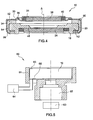
- Figure 4 shows a section of a further embodiment of the lens according to the invention.
- the lens 10 according to the invention comprises two transparent windows 24, 38 facing each other and parallel to one another, and delimiting, at least in part, an internal volume (15) containing two non-miscible liquids, with different optical indices, defining an optical interface (non represented on figure 4 ).
- the windows are transparent plates, made in an optical transparent material, e.g. in glass.
- at least one of the windows could be a fixed optical length, centred on the optical axis ( ⁇ ) of the variable focus lens.
- the lens comprises a cap 30 connected to one of the transparent windows 38 and comprising a first cylindrical side wall 34. It also comprises a body 16 having a symmetry of revolution, the axis of revolution defining the optical axis ( ⁇ ) of the lens.
- the body is connected to the other of the transparent windows (24) and comprises a second cylindrical side wall 20 of a diameter smaller than the diameter of the first cylindrical wall.
- the upper electrode consists of the cap 30 and the lower electrode consists of the body 16.
- a gasket 50 is provided to ensure the tightness of the lens mount. It is compressed between the first and second cylindrical side walls.
- the gasket comprises a skirt portion 54 compressed between the first and second cylindrical side walls and a portion 52 compressed between the cap and an intermediate part 42, forming in this example a single piece with the body, and comprising an opening defining a conical or cylindrical surface adjacent 48 where the interface between the two liquids is able to move.
- the lens further comprises an elastic means 36 capable of deforming in response to a change in pressure of the liquids.
- the elastic means comprise bent portions 36 formed on the upper wall 31 of the cap, said bent portions having symmetry of revolution about the optical axis ( ⁇ ) of the lens.
- the bent portions comprise at least one circular bend centred on the optical axis ( ⁇ ) of the lens.
- the cap can be made of a stamped metal, e.g. in stainless steel.
- the thickness of the upper wall of the cap will depend on the expected variations of volume to compensate for the effects of expansion of the liquids. For example, a typical thickness of about 0.1 to 0.25 mm has shown good results for lenses whose outer diameters is below 20 mm.
- the first side wall 34 comprises a rim 56 crimped onto the body 16 for the sealing of the cap onto the body.
- Other methods for sealing the cap onto the body are possible, for example it would be possible to glue the cap onto the body.
- the method for manufacturing the lens according to the invention as described in figure 4 can be similar to the method described previously.
- the method comprising the steps consisting in providing separately the cap 30 and the body 16, wherein windows 38 and 24 have been sealed to said cap and bodies. Then the gasket 50 is positioned between the first and second cylindrical side walls and the cap is positioned and sealed onto the body after the said internal volume has been filled with the two liquids.
- filling of the internal volume comprises immersing the body and the transparent window connected to it in a solution of the conducting liquid, placing a drop of insulating liquid in contact with the transparent window and positioning the gasket and the side wall of the cap, the body being kept immersed in the conducting solution.
- sealing the side wall of the cap onto the body is performed with the body being kept immersed in the conducting solution to avoid introducing any air bubbles in the lens.
- the cap is provided with bent portions having symmetry of revolution about the axis ( ⁇ ) to perform said elastic means.
- sealing of the cap onto the body is performed by crimping the side wall of the cap onto the body to get a very good mechanical strength of the mount.
- the present invention can be varied and modified in various ways that will be apparent to the person skilled in the art.
- the abovementioned steps of the method may be modified.
- the introduction of the drop of insulating liquid at the lower part 14 of the mount 10 may be performed before the mount is immersed in the conducting liquid.
- Figure 5 represents the schema of an example of an optical device 60 incorporating a lens 10 of variable focal length according to the invention.
- Said optical device comprises a mount 61 to hold the variable focus length 10 and a group 62 of fixed lens. It further comprises a driver 64 for driving the lens, said driver being connected to the electrodes of the lens through the connections 65, 66.
- the optical device can be incorporated in many systems in which there is a need for miniaturized variable focal length optical devices, like for example, mobile phones, endoscope systems, etc.
Claims (24)
- Lentille (10) à longueur focale variable ayant un axe optique (Δ), comprenant deux fenêtres transparentes (24, 38) au moins partiellement en vis-à-vis et parallèles entre elles et délimitant, au moins en partie, un volume intérieur (15) contenant deux liquides non miscibles, ayant des indices optiques différents, définissant une interface, la lentille comprenant :un capuchon (30) connecté à l'une des fenêtres transparentes (38) et comprenant une première paroi latérale cylindrique ;un corps (16) ayant une symétrie de révolution autour d'un axe définissant l'axe optique (Δ) de la lentille, connecté à l'autre des fenêtres transparentes (24) et comprenant une deuxième paroi latérale cylindrique (20) ayant un diamètre inférieur au diamètre de la première paroi cylindrique ;un joint (50) comprimé entre les première et deuxième parois latérales cylindriques, etun moyen élastique (36) capable d'une déformation en réponse à un changement de pression des liquides.
- Lentille (10) selon la revendication 1, dans laquelle le moyen élastique a une symétrie de révolution autour de l'axe optique (Δ) de la lentille.
- Lentille selon la revendication 1, comprenant en outre une pièce intermédiaire (42), connectée au corps ou formant une seule pièce avec le corps, et comprenant une ouverture définissant une surface conique ou cylindrique adjacente (48) où l'interface entre les deux liquides peut se déplacer.
- Lentille selon la revendication 3, dans laquelle le joint (50) comprend une première partie (52) comprimée entre le capuchon et la pièce intermédiaire et une partie de jupe (54) comprimée entre les première et deuxième parois latérales cylindriques.
- Lentille selon la revendication 4, dans laquelle la première partie comprimée entre le capuchon et la pièce intermédiaire est torique.
- Lentille selon la revendication 1, dans laquelle le capuchon comprend une paroi supérieure (31) connectée à la fenêtre transparente et prolongée par la première paroi latérale cylindrique et le moyen élastique comprend des portions courbées (36) formées sur la paroi supérieure du capuchon, avec une symétrie de révolution autour de l'axe optique (Δ) de la lentille.
- Lentille selon la revendication 6, dans lequel les parties courbées comprennent au moins une courbure circulaire centrée sur l'axe optique (Δ) de la lentille.
- Lentille selon la revendication 6, dans laquelle le capuchon est en métal embouti.
- Lentille selon la revendication 8, dans laquelle l'épaisseur de la paroi supérieure du capuchon est d'environ 0,1 à 0,25 mm.
- Lentille selon la revendication 3, dans laquelle la surface a une rugosité définie par un paramètre de rugosité Ra inférieur à 0,1 µm.
- Lentille selon la revendication 1, dans laquelle la première paroi latérale (34) comprend un rebord (56) serti sur le corps (16).
- Lentille selon la revendication 3, comprenant une couche d'étanchéité entre la pièce intermédiaire (42) et la fenêtre transparente (24) associée et/ou entre le corps (16) et la fenêtre transparente.
- Lentille selon la revendication 1, dans laquelle le corps (16) et/ou le capuchon (30) sont connectés à la fenêtre transparente associée (24, 38) par un verre filtrant (22, 40) recouvert d'une couche protectrice à base de composés organiques.
- Lentille selon la revendication 1, dans laquelle les fenêtres (24, 38) sont des plaques transparentes.
- Lentille selon la revendication 1, dans laquelle au moins une des fenêtres est une lentille fixe.
- Dispositif optique comprenant une lentille à longueur focale variable selon l'une quelconque des revendications 1 à 15.
- Téléphone mobile comprenant un dispositif optique selon la revendication 16.
- Procédé de fabrication d'une lentille à longueur focale variable ayant un axe optique (Δ), comprenant deux fenêtres transparentes au moins partiellement en vis-à-vis et parallèles entre elles, et délimitant, au moins en partie, un volume interne (15) contenant un liquide conducteur et un liquide isolant, non miscibles, ayant des indices optiques différents et définissant une interface, la lentille comprenant en outre un moyen élastique (36) capable d'une déformation en réponse à un changement de pression des liquides, le procédé comprenant les étapes suivantes :prévoir un capuchon (30) ayant une symétrie de révolution autour d'un axe (Δ), dans la partie centrale duquel passe une ouverture cylindrique, et qui est prolongé par une première paroi latérale cylindrique, l'une des fenêtres transparentes étant scellée sur le capuchon pour couvrir l'ouverture ;prévoir un corps (16) à travers la partie centrale duquel passe une deuxième ouverture cylindrique, et qui est prolongé par une deuxième paroi latérale cylindrique (20) ayant un diamètre inférieur au diamètre de la première paroi cylindrique, l'autre fenêtre transparente étant scellée sur le corps pour couvrir l'ouverture ;positionner un joint (50) entre les première et deuxième parois latérales cylindriques ; etpositionner et sceller le capuchon sur le corps après avoir rempli le volume interne avec les deux liquides.
- Procédé selon la revendication 18, comprenant :positionner, au niveau du corps, une pièce intermédiaire (42) comprenant une ouverture définissant une surface conique ou cylindrique où l'interface peut de se déplacer.
- Procédé selon la revendication 18, dans lequel le remplissage du volume interne comprend :immerger le corps et la fenêtre transparente qui lui est connectée dans une solution du liquide conducteur ;placer une goutte de liquide isolant en contact avec la fenêtre transparente ;positionner le joint et la paroi latérale du capuchon, le corps étant maintenu immergé dans la solution conductrice.
- Procédé selon la revendication 20, dans lequel le scellement de la paroi latérale du capuchon sur le corps est effectué en maintenant le corps immergé dans la solution conductrice.
- Procédé selon la revendication 18, dans lequel le capuchon est muni de parties courbées ayant une symétrie de révolution autour de l'axe (Δ) pour réaliser ledit moyen élastique.
- Procédé selon la revendication 22, dans lequel le capuchon est en métal embouti.
- Procédé selon la revendication 18, dans lequel le scellement du capuchon sur le corps est effectué en sertissant la paroi latérale du capuchon sur le corps.
Applications Claiming Priority (1)
| Application Number | Priority Date | Filing Date | Title |
|---|---|---|---|
| FR0452747A FR2878338B1 (fr) | 2004-11-24 | 2004-11-24 | Monture de lentille a focale variable |
Publications (2)
| Publication Number | Publication Date |
|---|---|
| EP1662276A1 EP1662276A1 (fr) | 2006-05-31 |
| EP1662276B1 true EP1662276B1 (fr) | 2010-02-17 |
Family
ID=34950692
Family Applications (1)
| Application Number | Title | Priority Date | Filing Date |
|---|---|---|---|
| EP05111183A Active EP1662276B1 (fr) | 2004-11-24 | 2005-11-23 | Lentille à focale variable |
Country Status (10)
| Country | Link |
|---|---|
| US (1) | US7515350B2 (fr) |
| EP (1) | EP1662276B1 (fr) |
| JP (1) | JP4764145B2 (fr) |
| KR (1) | KR20060058020A (fr) |
| CN (1) | CN100541236C (fr) |
| AT (1) | ATE458207T1 (fr) |
| DE (1) | DE602005019365D1 (fr) |
| FR (1) | FR2878338B1 (fr) |
| HK (1) | HK1088400A1 (fr) |
| TW (1) | TWI413806B (fr) |
Cited By (1)
| Publication number | Priority date | Publication date | Assignee | Title |
|---|---|---|---|---|
| EP2698979A1 (fr) | 2012-08-16 | 2014-02-19 | Wincor Nixdorf International GmbH | Dispositif et procédé de présentation dýobjets |
Families Citing this family (72)
| Publication number | Priority date | Publication date | Assignee | Title |
|---|---|---|---|---|
| FR2769375B1 (fr) * | 1997-10-08 | 2001-01-19 | Univ Joseph Fourier | Lentille a focale variable |
| US7646544B2 (en) * | 2005-05-14 | 2010-01-12 | Batchko Robert G | Fluidic optical devices |
| AU2002232910A1 (en) * | 2000-10-20 | 2002-04-29 | Robert Batchko | Combinatorial optical processor |
| US7672059B2 (en) * | 2000-10-20 | 2010-03-02 | Holochip Corporation | Fluidic lens with electrostatic actuation |
| FR2883985B1 (fr) * | 2005-03-30 | 2007-12-07 | Varioptic Sa | Procede et dispositif de commande d'une lentille a focale variable |
| US8503875B2 (en) * | 2008-11-17 | 2013-08-06 | Holochip Corporation | Fluidic viewfinder device |
| US7948683B2 (en) * | 2006-05-14 | 2011-05-24 | Holochip Corporation | Fluidic lens with manually-adjustable focus |
| US7697214B2 (en) | 2005-05-14 | 2010-04-13 | Holochip Corporation | Fluidic lens with manually-adjustable focus |
| US8064142B2 (en) | 2005-05-14 | 2011-11-22 | Holochip Corporation | Fluidic lens with reduced optical aberration |
| FR2887638B1 (fr) * | 2005-06-23 | 2007-08-31 | Varioptic Sa | Lentille a focale variable a variation de pression interne reduite |
| KR20080091790A (ko) * | 2006-02-01 | 2008-10-14 | 바리옵틱 | 광학 전자습윤 디바이스 및 이를 포함하는 장치 |
| EP1879055B8 (fr) * | 2006-07-12 | 2012-08-01 | Parrot | Interconnexion avec une lentille liquide |
| EP1906213A1 (fr) * | 2006-09-29 | 2008-04-02 | Varioptic | Dispositif d'électromouillage à électrode segmentée |
| US7755841B2 (en) * | 2007-01-30 | 2010-07-13 | Dmetrix, Inc. | Liquid-lens variable-control optics in array microscope |
| WO2008118085A2 (fr) * | 2007-03-28 | 2008-10-02 | Anoto Ab | Différents aspects de stylos électroniques |
| WO2008138005A1 (fr) * | 2007-05-08 | 2008-11-13 | Holochip Corporation | Lentille fluidique avec foyer réglable manuellement |
| EP1992968B1 (fr) * | 2007-05-14 | 2011-04-06 | Varioptic | Boîtier pour lentilles variables |
| EP2206013A4 (fr) * | 2007-05-31 | 2011-07-20 | Artificial Muscle Inc | Systèmes optiques employant des matériaux éléctroactifs compatibles |
| EP2009468B1 (fr) * | 2007-06-29 | 2011-10-19 | Varioptic | Dispositif d'électromouillage à électrode de polymère |
| EP2174360A4 (fr) | 2007-06-29 | 2013-12-11 | Artificial Muscle Inc | Transducteurs polymères électroactifs pour des applications de rétroaction sensorielle |
| US20090027544A1 (en) * | 2007-07-25 | 2009-01-29 | Micron Technology, Inc. | Solid state optical motion compensation |
| EP2034338A1 (fr) * | 2007-08-11 | 2009-03-11 | ETH Zurich | Système de lentille liquide |
| DE102007040099A1 (de) * | 2007-08-24 | 2009-02-26 | Elringklinger Ag | Dichtungsring |
| US20090072037A1 (en) * | 2007-09-17 | 2009-03-19 | Metrologic Instruments, Inc. | Autofocus liquid lens scanner |
| WO2009048725A1 (fr) * | 2007-10-08 | 2009-04-16 | Blackeye Optics, Llc | Objectif à focale variable à optique liquide et appareil d'imagerie |
| US7688518B2 (en) * | 2007-10-29 | 2010-03-30 | Corning Incorporated | Fluid lens lateral shifting |
| WO2009073387A1 (fr) | 2007-12-04 | 2009-06-11 | Blackeye Optics, Llc | Objectif de type téléobjectif ayant une lentille liquide dans un groupe fixe |
| EP2217960B1 (fr) * | 2007-12-04 | 2017-06-07 | Blackeye Optics, LLC | Système de stabilisation d'image comprenant deux lentilles liquides |
| EP2071367A1 (fr) | 2007-12-13 | 2009-06-17 | Varioptic | Circuit de stabilisation d'image pour lentille liquide |
| DE102007061743A1 (de) | 2007-12-20 | 2009-06-25 | Robert Bosch Gmbh | Verfahren zum Prüfen eines optischen Regensensors |
| US20090295683A1 (en) * | 2008-05-27 | 2009-12-03 | Randall Pugh | Head mounted display with variable focal length lens |
| JP2010032706A (ja) * | 2008-07-28 | 2010-02-12 | Sony Corp | 液体レンズ装置及びその製造方法 |
| CN101650445B (zh) * | 2008-08-13 | 2012-12-26 | 菱光科技股份有限公司 | 液态透镜元件及其制作方法 |
| US8366001B2 (en) * | 2008-08-14 | 2013-02-05 | Varioptic S.A. | Calibration methods for imaging systems and imaging systems using such |
| JP2010054864A (ja) * | 2008-08-28 | 2010-03-11 | Sony Corp | 液体レンズ素子及び照明装置 |
| CN102264275A (zh) * | 2008-11-21 | 2011-11-30 | 卡尔斯特里姆保健公司 | 具有液体透镜的自动对焦口腔内窥镜 |
| EP2192425A1 (fr) | 2008-11-26 | 2010-06-02 | Samsung Electronics Co., Ltd. | Lentille à focale variable et son procédé de fabrication |
| WO2010073127A2 (fr) | 2008-12-23 | 2010-07-01 | Varioptic S.A. | Dispositif d'électromouillage optique |
| CN102388332A (zh) * | 2009-04-10 | 2012-03-21 | 黑眼睛光学有限公司 | 可变焦度光学系统 |
| JP5738841B2 (ja) | 2009-04-10 | 2015-06-24 | ブラックアイ オプティクス,エルエルシー | 可変屈折力光学系 |
| EP2239793A1 (fr) | 2009-04-11 | 2010-10-13 | Bayer MaterialScience AG | Montage de film polymère électrique commutable et son utilisation |
| JP2010250126A (ja) * | 2009-04-16 | 2010-11-04 | Sony Corp | 液体レンズ装置の製造方法及び液体レンズ装置 |
| US9164202B2 (en) | 2010-02-16 | 2015-10-20 | Holochip Corporation | Adaptive optical devices with controllable focal power and aspheric shape |
| US8260129B2 (en) | 2009-12-23 | 2012-09-04 | Varioptic, S.A. | Optical device for high quality and compact camera module |
| GB2477264B (en) | 2010-01-18 | 2015-02-25 | Gici Labs Llp | Eyeglasses and means for their adjustment |
| DE112010005015A5 (de) * | 2010-04-01 | 2012-11-22 | Conti Temic Microelectronic Gmbh | Vorrichtung mit optischem Modul und Objektivhalter |
| US8408745B2 (en) * | 2010-09-15 | 2013-04-02 | B.E. Meyers & Co. Inc. | Illuminating and targeting systems and methods having variable liquid lens |
| US20120092774A1 (en) * | 2010-09-27 | 2012-04-19 | Pugh Randall B | Lens with multi-segmented linear meniscus wall |
| SG193003A1 (en) | 2011-03-01 | 2013-10-30 | Bayer Ip Gmbh | Automated manufacturing processes for producing deformable polymer devices and films |
| WO2012129357A2 (fr) | 2011-03-22 | 2012-09-27 | Bayer Materialscience Ag | Système lenticulaire à actionneur à polymère électroactif |
| US8717680B2 (en) | 2011-05-06 | 2014-05-06 | Nokia Corporation | Apparatus and associated methods |
| DE102011081491A1 (de) * | 2011-08-24 | 2013-02-28 | Endress + Hauser Flowtec Ag | L-Dichtring |
| DE102011054072B4 (de) | 2011-09-30 | 2013-08-29 | Qioptiq Photonics Gmbh & Co. Kg | Linsenhalterung für Flüssiglinsen sowie Dentalkamera mit einer in einer Linsenhalterung aufgenommenen Flüssiglinse |
| EP2828901B1 (fr) | 2012-03-21 | 2017-01-04 | Parker Hannifin Corporation | Procédés de fabrication de rouleau à rouleau pour la production de dispositifs à polymère électroactif autoréparant |
| KR20150031285A (ko) | 2012-06-18 | 2015-03-23 | 바이엘 인텔렉쳐 프로퍼티 게엠베하 | 연신 공정을 위한 연신 프레임 |
| US9590193B2 (en) | 2012-10-24 | 2017-03-07 | Parker-Hannifin Corporation | Polymer diode |
| WO2014121082A1 (fr) * | 2013-02-01 | 2014-08-07 | The General Hospital Corporation | Agencement d'objectif pour endomicroscopie confocale |
| US9225885B2 (en) * | 2013-06-14 | 2015-12-29 | Microsoft Technology Licensing, Llc | Reduced height camera module for small form factor applications |
| US9910493B2 (en) * | 2014-11-07 | 2018-03-06 | Faurecia Interior Systems, Inc. | Suspension component for a haptic touch panel assembly |
| KR20180088204A (ko) * | 2017-01-26 | 2018-08-03 | 엘지이노텍 주식회사 | 액체렌즈 및 이를 포함하는 카메라 모듈 및 광학기기 |
| CN110546543B (zh) | 2017-02-09 | 2022-03-08 | 康宁股份有限公司 | 液体透镜 |
| KR20180094615A (ko) | 2017-02-16 | 2018-08-24 | 엘지이노텍 주식회사 | 액체 렌즈 및 이를 포함하는 카메라 모듈 |
| US10994274B2 (en) | 2017-07-12 | 2021-05-04 | Sharp Life Science (Eu) Limited | Housing for simple assembly of an EWOD device |
| US10926256B2 (en) | 2017-07-12 | 2021-02-23 | Sharp Life Science (Eu) Limited | Housing for simple assembly of an EWOD device |
| WO2019028207A1 (fr) | 2017-08-02 | 2019-02-07 | Corning Incorporated | Substrat flexible et circuit pour système de lentille liquide |
| US11608288B2 (en) | 2017-10-13 | 2023-03-21 | Corning Incorporated | Methods and apparatus for pressing glass or glass-ceramic preforms to form shaped plates, methods for manufacturing liquid lenses, and liquid lenses |
| KR20190133544A (ko) * | 2018-05-23 | 2019-12-03 | 엘지이노텍 주식회사 | 액체 렌즈 및 이를 포함하는 렌즈 어셈블리 |
| TWI824011B (zh) * | 2018-09-21 | 2023-12-01 | 美商康寧公司 | 一種體積可變的液體透鏡及照相機系統 |
| CN109254397A (zh) * | 2018-11-02 | 2019-01-22 | 上海酷聚科技有限公司 | 一种液体透镜及其制造方法 |
| CN110967783B (zh) * | 2019-04-18 | 2021-06-01 | 华为技术有限公司 | 驱动液态镜头的马达组件、摄像头模组和电子设备 |
| US11813607B2 (en) | 2019-08-26 | 2023-11-14 | Corning Incorporated | Thermally compensated microfluidic structures |
| CH716546A1 (fr) | 2019-08-29 | 2021-03-15 | Haute Ecole Arc | Dispositif d'usinage laser et procédé de trépanation optique. |
Family Cites Families (17)
| Publication number | Priority date | Publication date | Assignee | Title |
|---|---|---|---|---|
| JPH02124516A (ja) * | 1988-11-02 | 1990-05-11 | Canon Inc | 光学素子 |
| US5436766A (en) * | 1992-09-04 | 1995-07-25 | Lockheed Missiles & Space Company, Inc. | Bond between a rigid refractive element and a surrounding housing structure in an optical system containing a liquid refractive element |
| CA2265723C (fr) | 1996-09-13 | 2008-03-11 | Joshua David Silver | Perfectionnements relatifs a des objectifs a focale variable |
| FR2769375B1 (fr) | 1997-10-08 | 2001-01-19 | Univ Joseph Fourier | Lentille a focale variable |
| US20050002113A1 (en) | 1997-10-08 | 2005-01-06 | Varioptic | Drop centering device |
| JP2002162506A (ja) * | 2000-11-27 | 2002-06-07 | Canon Inc | 光学素子、光学装置および撮影装置 |
| JP2003029005A (ja) * | 2001-07-19 | 2003-01-29 | Canon Inc | 光学素子および光学機器 |
| JP2003057409A (ja) * | 2001-08-21 | 2003-02-26 | Canon Inc | 光学素子および光学機器 |
| WO2004099847A1 (fr) * | 2003-05-09 | 2004-11-18 | Koninklijke Philips Electronics N.V. | Cellules d'electromouillage |
| JP2004341032A (ja) * | 2003-05-13 | 2004-12-02 | Olympus Corp | 撮像ユニット及び撮像装置 |
| US7436598B2 (en) * | 2003-05-14 | 2008-10-14 | Koninklijke Philips Electronics N.V. | Variable shape lens |
| WO2005006312A2 (fr) * | 2003-07-14 | 2005-01-20 | Koninklijke Philips Electronics N.V. | Element conformateur de faisceau variable |
| US7245439B2 (en) * | 2003-07-14 | 2007-07-17 | Koninklijke Philips Electronics N.V. | Variable lens |
| WO2005069043A1 (fr) * | 2004-01-12 | 2005-07-28 | Koninklijke Philips Electronics N.V. | Dispositif d'electromouillage |
| JP2007519971A (ja) * | 2004-01-30 | 2007-07-19 | コーニンクレッカ フィリップス エレクトロニクス エヌ ヴィ | 可変焦点レンズパッケージにより含有された流体の容積差を補償するための封止リングを有する可変焦点レンズパッケージ |
| GB0407414D0 (en) * | 2004-04-01 | 2004-05-05 | 1 Ltd | Variable focal length lens |
| JP2007536591A (ja) * | 2004-05-07 | 2007-12-13 | コーニンクレッカ フィリップス エレクトロニクス エヌ ヴィ | エレクトロウェッティングセル及びその製造方法 |
-
2004
- 2004-11-24 FR FR0452747A patent/FR2878338B1/fr not_active Expired - Fee Related
-
2005
- 2005-11-14 TW TW094139875A patent/TWI413806B/zh not_active IP Right Cessation
- 2005-11-22 US US11/284,125 patent/US7515350B2/en active Active
- 2005-11-22 KR KR1020050111746A patent/KR20060058020A/ko not_active Application Discontinuation
- 2005-11-22 JP JP2005336632A patent/JP4764145B2/ja active Active
- 2005-11-23 DE DE602005019365T patent/DE602005019365D1/de active Active
- 2005-11-23 AT AT05111183T patent/ATE458207T1/de not_active IP Right Cessation
- 2005-11-23 EP EP05111183A patent/EP1662276B1/fr active Active
- 2005-11-24 CN CNB2005101272396A patent/CN100541236C/zh active Active
-
2006
- 2006-08-08 HK HK06108794.5A patent/HK1088400A1/xx not_active IP Right Cessation
Cited By (1)
| Publication number | Priority date | Publication date | Assignee | Title |
|---|---|---|---|---|
| EP2698979A1 (fr) | 2012-08-16 | 2014-02-19 | Wincor Nixdorf International GmbH | Dispositif et procédé de présentation dýobjets |
Also Published As
| Publication number | Publication date |
|---|---|
| ATE458207T1 (de) | 2010-03-15 |
| HK1088400A1 (en) | 2006-11-03 |
| TWI413806B (zh) | 2013-11-01 |
| KR20060058020A (ko) | 2006-05-29 |
| US7515350B2 (en) | 2009-04-07 |
| DE602005019365D1 (de) | 2010-04-01 |
| CN1782746A (zh) | 2006-06-07 |
| EP1662276A1 (fr) | 2006-05-31 |
| JP4764145B2 (ja) | 2011-08-31 |
| TW200624874A (en) | 2006-07-16 |
| JP2006146235A (ja) | 2006-06-08 |
| FR2878338B1 (fr) | 2007-03-02 |
| CN100541236C (zh) | 2009-09-16 |
| FR2878338A1 (fr) | 2006-05-26 |
| US20060126190A1 (en) | 2006-06-15 |
Similar Documents
| Publication | Publication Date | Title |
|---|---|---|
| EP1662276B1 (fr) | Lentille à focale variable | |
| US8238033B2 (en) | Liquid lens device and manufacturing method therefor | |
| JP5070517B2 (ja) | 気密エレクトロウェッティング装置 | |
| EP2105768B1 (fr) | Lentille optique fluidique avec un actionneur polymèrique électrostrictif | |
| EP1625438B1 (fr) | Cellules d'electromouillage | |
| KR101225596B1 (ko) | 가변-초점 렌즈 | |
| US20070002455A1 (en) | Variable-focus lens and method of manufacturing the same | |
| US20100254021A1 (en) | Liquid lens device and manufacturing method therefor | |
| EP2085796A1 (fr) | Agencement de lentille optique pour lentilles fixées et lentille liquide | |
| JP2007536593A (ja) | エレクトロウェッティングセル及びそれを駆動する方法 | |
| US20100149651A1 (en) | Variable-focus lens assembly | |
| JP2006146235A5 (fr) | ||
| EP1804090B1 (fr) | Procédé de fabrication de lentille liquide utilisant l électromouillage et une lentille liquide fabriquée à l aide de ce procédé | |
| CN115963588A (zh) | 自适应透镜 | |
| EP1801622A1 (fr) | Scellement direct d'un dispositif optique liquide | |
| CN211603595U (zh) | 液体透镜及包括该液体透镜的照相机系统 | |
| EP1795925A1 (fr) | Lentille liquide mince | |
| CN116547570A (zh) | 构造用于耐热暴露的液体透镜及其制造方法 |
Legal Events
| Date | Code | Title | Description |
|---|---|---|---|
| PUAI | Public reference made under article 153(3) epc to a published international application that has entered the european phase |
Free format text: ORIGINAL CODE: 0009012 |
|
| AK | Designated contracting states |
Kind code of ref document: A1 Designated state(s): AT BE BG CH CY CZ DE DK EE ES FI FR GB GR HU IE IS IT LI LT LU LV MC NL PL PT RO SE SI SK TR |
|
| AX | Request for extension of the european patent |
Extension state: AL BA HR MK YU |
|
| RIN1 | Information on inventor provided before grant (corrected) |
Inventor name: BERGE, BRUNO Inventor name: PESEUX, JEROME Inventor name: LAUNE, FREDERIC |
|
| 17P | Request for examination filed |
Effective date: 20061130 |
|
| 17Q | First examination report despatched |
Effective date: 20070103 |
|
| AKX | Designation fees paid |
Designated state(s): AT BE BG CH CY CZ DE DK EE ES FI FR GB GR HU IE IS IT LI LT LU LV MC NL PL PT RO SE SI SK TR |
|
| GRAP | Despatch of communication of intention to grant a patent |
Free format text: ORIGINAL CODE: EPIDOSNIGR1 |
|
| GRAS | Grant fee paid |
Free format text: ORIGINAL CODE: EPIDOSNIGR3 |
|
| GRAA | (expected) grant |
Free format text: ORIGINAL CODE: 0009210 |
|
| AK | Designated contracting states |
Kind code of ref document: B1 Designated state(s): AT BE BG CH CY CZ DE DK EE ES FI FR GB GR HU IE IS IT LI LT LU LV MC NL PL PT RO SE SI SK TR |
|
| REG | Reference to a national code |
Ref country code: GB Ref legal event code: FG4D |
|
| REG | Reference to a national code |
Ref country code: CH Ref legal event code: EP |
|
| REG | Reference to a national code |
Ref country code: IE Ref legal event code: FG4D |
|
| REF | Corresponds to: |
Ref document number: 602005019365 Country of ref document: DE Date of ref document: 20100401 Kind code of ref document: P |
|
| REG | Reference to a national code |
Ref country code: NL Ref legal event code: VDEP Effective date: 20100217 |
|
| LTIE | Lt: invalidation of european patent or patent extension |
Effective date: 20100217 |
|
| PG25 | Lapsed in a contracting state [announced via postgrant information from national office to epo] |
Ref country code: PT Free format text: LAPSE BECAUSE OF FAILURE TO SUBMIT A TRANSLATION OF THE DESCRIPTION OR TO PAY THE FEE WITHIN THE PRESCRIBED TIME-LIMIT Effective date: 20100617 Ref country code: IS Free format text: LAPSE BECAUSE OF FAILURE TO SUBMIT A TRANSLATION OF THE DESCRIPTION OR TO PAY THE FEE WITHIN THE PRESCRIBED TIME-LIMIT Effective date: 20100617 Ref country code: ES Free format text: LAPSE BECAUSE OF FAILURE TO SUBMIT A TRANSLATION OF THE DESCRIPTION OR TO PAY THE FEE WITHIN THE PRESCRIBED TIME-LIMIT Effective date: 20100528 Ref country code: LT Free format text: LAPSE BECAUSE OF FAILURE TO SUBMIT A TRANSLATION OF THE DESCRIPTION OR TO PAY THE FEE WITHIN THE PRESCRIBED TIME-LIMIT Effective date: 20100217 |
|
| PG25 | Lapsed in a contracting state [announced via postgrant information from national office to epo] |
Ref country code: AT Free format text: LAPSE BECAUSE OF FAILURE TO SUBMIT A TRANSLATION OF THE DESCRIPTION OR TO PAY THE FEE WITHIN THE PRESCRIBED TIME-LIMIT Effective date: 20100217 Ref country code: PL Free format text: LAPSE BECAUSE OF FAILURE TO SUBMIT A TRANSLATION OF THE DESCRIPTION OR TO PAY THE FEE WITHIN THE PRESCRIBED TIME-LIMIT Effective date: 20100217 Ref country code: FI Free format text: LAPSE BECAUSE OF FAILURE TO SUBMIT A TRANSLATION OF THE DESCRIPTION OR TO PAY THE FEE WITHIN THE PRESCRIBED TIME-LIMIT Effective date: 20100217 Ref country code: LV Free format text: LAPSE BECAUSE OF FAILURE TO SUBMIT A TRANSLATION OF THE DESCRIPTION OR TO PAY THE FEE WITHIN THE PRESCRIBED TIME-LIMIT Effective date: 20100217 Ref country code: SI Free format text: LAPSE BECAUSE OF FAILURE TO SUBMIT A TRANSLATION OF THE DESCRIPTION OR TO PAY THE FEE WITHIN THE PRESCRIBED TIME-LIMIT Effective date: 20100217 |
|
| PG25 | Lapsed in a contracting state [announced via postgrant information from national office to epo] |
Ref country code: EE Free format text: LAPSE BECAUSE OF FAILURE TO SUBMIT A TRANSLATION OF THE DESCRIPTION OR TO PAY THE FEE WITHIN THE PRESCRIBED TIME-LIMIT Effective date: 20100217 Ref country code: CY Free format text: LAPSE BECAUSE OF FAILURE TO SUBMIT A TRANSLATION OF THE DESCRIPTION OR TO PAY THE FEE WITHIN THE PRESCRIBED TIME-LIMIT Effective date: 20100217 Ref country code: SE Free format text: LAPSE BECAUSE OF FAILURE TO SUBMIT A TRANSLATION OF THE DESCRIPTION OR TO PAY THE FEE WITHIN THE PRESCRIBED TIME-LIMIT Effective date: 20100217 Ref country code: RO Free format text: LAPSE BECAUSE OF FAILURE TO SUBMIT A TRANSLATION OF THE DESCRIPTION OR TO PAY THE FEE WITHIN THE PRESCRIBED TIME-LIMIT Effective date: 20100217 Ref country code: GR Free format text: LAPSE BECAUSE OF FAILURE TO SUBMIT A TRANSLATION OF THE DESCRIPTION OR TO PAY THE FEE WITHIN THE PRESCRIBED TIME-LIMIT Effective date: 20100518 Ref country code: NL Free format text: LAPSE BECAUSE OF FAILURE TO SUBMIT A TRANSLATION OF THE DESCRIPTION OR TO PAY THE FEE WITHIN THE PRESCRIBED TIME-LIMIT Effective date: 20100217 Ref country code: BE Free format text: LAPSE BECAUSE OF FAILURE TO SUBMIT A TRANSLATION OF THE DESCRIPTION OR TO PAY THE FEE WITHIN THE PRESCRIBED TIME-LIMIT Effective date: 20100217 |
|
| PG25 | Lapsed in a contracting state [announced via postgrant information from national office to epo] |
Ref country code: CZ Free format text: LAPSE BECAUSE OF FAILURE TO SUBMIT A TRANSLATION OF THE DESCRIPTION OR TO PAY THE FEE WITHIN THE PRESCRIBED TIME-LIMIT Effective date: 20100217 Ref country code: BG Free format text: LAPSE BECAUSE OF FAILURE TO SUBMIT A TRANSLATION OF THE DESCRIPTION OR TO PAY THE FEE WITHIN THE PRESCRIBED TIME-LIMIT Effective date: 20100517 Ref country code: SK Free format text: LAPSE BECAUSE OF FAILURE TO SUBMIT A TRANSLATION OF THE DESCRIPTION OR TO PAY THE FEE WITHIN THE PRESCRIBED TIME-LIMIT Effective date: 20100217 |
|
| PLBE | No opposition filed within time limit |
Free format text: ORIGINAL CODE: 0009261 |
|
| STAA | Information on the status of an ep patent application or granted ep patent |
Free format text: STATUS: NO OPPOSITION FILED WITHIN TIME LIMIT |
|
| 26N | No opposition filed |
Effective date: 20101118 |
|
| PG25 | Lapsed in a contracting state [announced via postgrant information from national office to epo] |
Ref country code: DK Free format text: LAPSE BECAUSE OF FAILURE TO SUBMIT A TRANSLATION OF THE DESCRIPTION OR TO PAY THE FEE WITHIN THE PRESCRIBED TIME-LIMIT Effective date: 20100217 |
|
| PG25 | Lapsed in a contracting state [announced via postgrant information from national office to epo] |
Ref country code: IT Free format text: LAPSE BECAUSE OF FAILURE TO SUBMIT A TRANSLATION OF THE DESCRIPTION OR TO PAY THE FEE WITHIN THE PRESCRIBED TIME-LIMIT Effective date: 20100217 |
|
| PG25 | Lapsed in a contracting state [announced via postgrant information from national office to epo] |
Ref country code: MC Free format text: LAPSE BECAUSE OF NON-PAYMENT OF DUE FEES Effective date: 20101130 |
|
| REG | Reference to a national code |
Ref country code: CH Ref legal event code: PL |
|
| PG25 | Lapsed in a contracting state [announced via postgrant information from national office to epo] |
Ref country code: CH Free format text: LAPSE BECAUSE OF NON-PAYMENT OF DUE FEES Effective date: 20101130 Ref country code: LI Free format text: LAPSE BECAUSE OF NON-PAYMENT OF DUE FEES Effective date: 20101130 |
|
| PG25 | Lapsed in a contracting state [announced via postgrant information from national office to epo] |
Ref country code: IE Free format text: LAPSE BECAUSE OF NON-PAYMENT OF DUE FEES Effective date: 20101123 |
|
| PG25 | Lapsed in a contracting state [announced via postgrant information from national office to epo] |
Ref country code: HU Free format text: LAPSE BECAUSE OF FAILURE TO SUBMIT A TRANSLATION OF THE DESCRIPTION OR TO PAY THE FEE WITHIN THE PRESCRIBED TIME-LIMIT Effective date: 20100818 Ref country code: LU Free format text: LAPSE BECAUSE OF NON-PAYMENT OF DUE FEES Effective date: 20101123 |
|
| PG25 | Lapsed in a contracting state [announced via postgrant information from national office to epo] |
Ref country code: TR Free format text: LAPSE BECAUSE OF FAILURE TO SUBMIT A TRANSLATION OF THE DESCRIPTION OR TO PAY THE FEE WITHIN THE PRESCRIBED TIME-LIMIT Effective date: 20100217 |
|
| REG | Reference to a national code |
Ref country code: FR Ref legal event code: TP Owner name: PARROT, FR Effective date: 20130916 |
|
| REG | Reference to a national code |
Ref country code: FR Ref legal event code: PLFP Year of fee payment: 11 |
|
| REG | Reference to a national code |
Ref country code: DE Ref legal event code: R082 Ref document number: 602005019365 Country of ref document: DE Representative=s name: DOMPATENT VON KREISLER SELTING WERNER - PARTNE, DE Ref country code: DE Ref legal event code: R082 Ref document number: 602005019365 Country of ref document: DE Representative=s name: JOSTARNDT PATENTANWALTS-AG, DE Ref country code: DE Ref legal event code: R081 Ref document number: 602005019365 Country of ref document: DE Owner name: PARROT DRONES, FR Free format text: FORMER OWNER: VARIOPTIC, LYON, FR Ref country code: DE Ref legal event code: R081 Ref document number: 602005019365 Country of ref document: DE Owner name: CORNING INCORPORATED, CORNING, US Free format text: FORMER OWNER: VARIOPTIC, LYON, FR |
|
| REG | Reference to a national code |
Ref country code: DE Ref legal event code: R082 Ref document number: 602005019365 Country of ref document: DE Representative=s name: DOMPATENT VON KREISLER SELTING WERNER - PARTNE, DE Ref country code: DE Ref legal event code: R082 Ref document number: 602005019365 Country of ref document: DE Representative=s name: JOSTARNDT PATENTANWALTS-AG, DE |
|
| REG | Reference to a national code |
Ref country code: FR Ref legal event code: PLFP Year of fee payment: 12 |
|
| REG | Reference to a national code |
Ref country code: FR Ref legal event code: TP Owner name: PARROT DRONES, FR Effective date: 20161011 |
|
| REG | Reference to a national code |
Ref country code: GB Ref legal event code: 732E Free format text: REGISTERED BETWEEN 20161103 AND 20161109 |
|
| REG | Reference to a national code |
Ref country code: GB Ref legal event code: 732E Free format text: REGISTERED BETWEEN 20161110 AND 20161116 |
|
| REG | Reference to a national code |
Ref country code: DE Ref legal event code: R082 Ref document number: 602005019365 Country of ref document: DE Representative=s name: DOMPATENT VON KREISLER SELTING WERNER - PARTNE, DE Ref country code: DE Ref legal event code: R082 Ref document number: 602005019365 Country of ref document: DE Representative=s name: JOSTARNDT PATENTANWALTS-AG, DE Ref country code: DE Ref legal event code: R081 Ref document number: 602005019365 Country of ref document: DE Owner name: CORNING INCORPORATED, CORNING, US Free format text: FORMER OWNER: PARROT DRONES, PARIS, FR |
|
| REG | Reference to a national code |
Ref country code: FR Ref legal event code: PLFP Year of fee payment: 13 |
|
| REG | Reference to a national code |
Ref country code: FR Ref legal event code: PLFP Year of fee payment: 14 |
|
| REG | Reference to a national code |
Ref country code: DE Ref legal event code: R082 Ref document number: 602005019365 Country of ref document: DE Representative=s name: DOMPATENT VON KREISLER SELTING WERNER - PARTNE, DE |
|
| REG | Reference to a national code |
Ref country code: GB Ref legal event code: 732E Free format text: REGISTERED BETWEEN 20200102 AND 20200108 |
|
| PGFP | Annual fee paid to national office [announced via postgrant information from national office to epo] |
Ref country code: FR Payment date: 20201023 Year of fee payment: 16 |
|
| PGFP | Annual fee paid to national office [announced via postgrant information from national office to epo] |
Ref country code: GB Payment date: 20211028 Year of fee payment: 17 |
|
| PG25 | Lapsed in a contracting state [announced via postgrant information from national office to epo] |
Ref country code: FR Free format text: LAPSE BECAUSE OF NON-PAYMENT OF DUE FEES Effective date: 20211130 |
|
| P01 | Opt-out of the competence of the unified patent court (upc) registered |
Effective date: 20230527 |
|
| GBPC | Gb: european patent ceased through non-payment of renewal fee |
Effective date: 20221123 |
|
| PG25 | Lapsed in a contracting state [announced via postgrant information from national office to epo] |
Ref country code: GB Free format text: LAPSE BECAUSE OF NON-PAYMENT OF DUE FEES Effective date: 20221123 |
|
| PGFP | Annual fee paid to national office [announced via postgrant information from national office to epo] |
Ref country code: DE Payment date: 20231010 Year of fee payment: 19 |