EP1538329A2 - Air filter for an internal combustion engine - Google Patents
Air filter for an internal combustion engine Download PDFInfo
- Publication number
- EP1538329A2 EP1538329A2 EP04026359A EP04026359A EP1538329A2 EP 1538329 A2 EP1538329 A2 EP 1538329A2 EP 04026359 A EP04026359 A EP 04026359A EP 04026359 A EP04026359 A EP 04026359A EP 1538329 A2 EP1538329 A2 EP 1538329A2
- Authority
- EP
- European Patent Office
- Prior art keywords
- air filter
- air
- resonator
- internal combustion
- combustion engine
- Prior art date
- Legal status (The legal status is an assumption and is not a legal conclusion. Google has not performed a legal analysis and makes no representation as to the accuracy of the status listed.)
- Granted
Links
- 238000002485 combustion reaction Methods 0.000 title claims description 11
- 239000004744 fabric Substances 0.000 claims abstract description 8
- 230000002209 hydrophobic effect Effects 0.000 claims description 3
- 230000005855 radiation Effects 0.000 claims 1
- 230000005540 biological transmission Effects 0.000 description 2
- 230000005284 excitation Effects 0.000 description 2
- XLYOFNOQVPJJNP-UHFFFAOYSA-N water Substances O XLYOFNOQVPJJNP-UHFFFAOYSA-N 0.000 description 2
- 230000015572 biosynthetic process Effects 0.000 description 1
- 230000001419 dependent effect Effects 0.000 description 1
- 238000011161 development Methods 0.000 description 1
- 230000018109 developmental process Effects 0.000 description 1
- 230000000694 effects Effects 0.000 description 1
- 239000012528 membrane Substances 0.000 description 1
- 238000000034 method Methods 0.000 description 1
Images

Classifications
-
- F—MECHANICAL ENGINEERING; LIGHTING; HEATING; WEAPONS; BLASTING
- F02—COMBUSTION ENGINES; HOT-GAS OR COMBUSTION-PRODUCT ENGINE PLANTS
- F02M—SUPPLYING COMBUSTION ENGINES IN GENERAL WITH COMBUSTIBLE MIXTURES OR CONSTITUENTS THEREOF
- F02M35/00—Combustion-air cleaners, air intakes, intake silencers, or induction systems specially adapted for, or arranged on, internal-combustion engines
- F02M35/14—Combined air cleaners and silencers
-
- F—MECHANICAL ENGINEERING; LIGHTING; HEATING; WEAPONS; BLASTING
- F02—COMBUSTION ENGINES; HOT-GAS OR COMBUSTION-PRODUCT ENGINE PLANTS
- F02M—SUPPLYING COMBUSTION ENGINES IN GENERAL WITH COMBUSTIBLE MIXTURES OR CONSTITUENTS THEREOF
- F02M35/00—Combustion-air cleaners, air intakes, intake silencers, or induction systems specially adapted for, or arranged on, internal-combustion engines
- F02M35/02—Air cleaners
- F02M35/0201—Housings; Casings; Frame constructions; Lids; Manufacturing or assembling thereof
- F02M35/0205—Details, e.g. sensors or measuring devices
- F02M35/0207—Details, e.g. sensors or measuring devices on the clean air side
-
- F—MECHANICAL ENGINEERING; LIGHTING; HEATING; WEAPONS; BLASTING
- F02—COMBUSTION ENGINES; HOT-GAS OR COMBUSTION-PRODUCT ENGINE PLANTS
- F02M—SUPPLYING COMBUSTION ENGINES IN GENERAL WITH COMBUSTIBLE MIXTURES OR CONSTITUENTS THEREOF
- F02M35/00—Combustion-air cleaners, air intakes, intake silencers, or induction systems specially adapted for, or arranged on, internal-combustion engines
- F02M35/12—Intake silencers ; Sound modulation, transmission or amplification
- F02M35/1205—Flow throttling or guiding
- F02M35/1222—Flow throttling or guiding by using adjustable or movable elements, e.g. valves, membranes, bellows, expanding or shrinking elements
-
- F—MECHANICAL ENGINEERING; LIGHTING; HEATING; WEAPONS; BLASTING
- F02—COMBUSTION ENGINES; HOT-GAS OR COMBUSTION-PRODUCT ENGINE PLANTS
- F02M—SUPPLYING COMBUSTION ENGINES IN GENERAL WITH COMBUSTIBLE MIXTURES OR CONSTITUENTS THEREOF
- F02M35/00—Combustion-air cleaners, air intakes, intake silencers, or induction systems specially adapted for, or arranged on, internal-combustion engines
- F02M35/12—Intake silencers ; Sound modulation, transmission or amplification
- F02M35/1255—Intake silencers ; Sound modulation, transmission or amplification using resonance
Definitions
- the invention relates to an air filter for internal combustion engine according to the features of Preamble of claim 1.
- an air filter for an internal combustion engine in which in the air filter housing an insert made of an air-permeable and fine-meshed textured fabric or a thin-walled sound element in the air filter housing covered opening covers. This can over the protected housing opening to Generating attractive exterior and interior noise on the vehicle Sound components off be emitted to the intake system.
- the object of the invention is even better at the effect of the sound device to adapt to the respective operating state of the internal combustion engine.
- the resonator volume which can be switched on or off by the resonator is advantageous and way integrated in the clean air bowl and is about a pipe section with a pipeline leading to the intake tract of the internal combustion engine, wherein in the pipe section a resonator volume on or off switchable Control is arranged.
- the controlling body is for example as formed vacuum-controlled flap element. Other embodiments of the Control body, such.
- the Resonatorvolumen controlling valves or membranes are also possible.
- tissue or the sound element is accommodated in a frame, which as Insert is secured in the housing opening introduced in the air filter housing.
- the resonator is disabled in the lower and middle speed range to the excitation of the higher engine orders for sound transmission with a discrete Frequency in the interior to use.
- the resonator active to lower the interior noise level, as in this area Resonance phenomena by the dominant gas exchange orders particularly strong emerge.
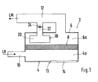
- the air filter housing 2 shown schematically in Fig. 1 consists of a Rohluftschale 4 and a clean air tray 6, both of which are tightly interconnected.
- an air filter 8 is arranged between these two shells 4 and 6, between these two shells 4 and 6, an air filter 8 is arranged.
- the feeder of unfiltered air LR in the housing 2 via a with the raw air space 4a in conjunction standing supply line 10 and then via the air filter 8 in the clean air space 6a and from there from the clean air LM via a supply line 12 to the intake of the Internal combustion engine supplied.
- an opening 13 is introduced into which a with a fabric structure provided insert member 14 is attached.
- the frame-like Insert 14 has a plurality of window-like openings 14a to 14e, of the technical tissue are covered.
- the technical fabric can be used on the Insert 14 sprayed on, welded, glued or clamped to the frame of Insert 14 to be attached.
- the insert 14 in turn can by means of a screw or Clip connection 16 to be attached to the clean air tray 4.
- the fabric ensures that by the swinging of the air column in the intake tract of the internal combustion engine On the other hand, it prevents sound components from being conducted to the outside Water, dirt or the like. From the outside via the opening 13 in the air filter housing. 2 can get.
- the tissue can optionally additionally be coated hydrophobic.
- the housing opening 13 through a thin-walled sound element is covered, the same or similar characteristics as having the tissue.
- the fabric or the sound element can oscillate in the process Insert 14 to be attached.
- a resonator 18 is integrated, the volume 20 via a pipe section 22 with the intake tract of the internal combustion engine leading supply line 12 is in communication.
- a Shut-off 24 arranged in the present embodiment as a flap formed and in its open position the resonator 20 with the Feed line 12 connects and in the closed state, the resonator 20 of the supply line 12 and thus separated from the intake of the engine.
- the flap member 24 via a linkage 26 with a Vacuum box 28 connected.
- the vacuum unit 28 is connected via a pressure line 30 with a vacuum accumulator, not shown, connected by a in the Pressure line 30 arranged switching valve 32, the connection between the pressure box 28th and vacuum reservoir is switched on or off.
- the resonator volume 20 is in the lower and middle speed range by closing the flap 24 separated from the intake of the engine to the excitation of the higher engine orders for sound transmission at a discrete frequency in the Interior to use.
- the flap 24 is opened and thus the resonator activates to the outgoing sound or sound level lower in this speed range due to resonance phenomena, stimulated by the dominant gas exchange regulations, especially in the intake system is highly trained.
Abstract
Description
Die Erfindung betrifft einen Luftfilter für Brennkraftmaschine gemäß den Merkmalen des Oberbegriffs des Patentanspruchs 1.The invention relates to an air filter for internal combustion engine according to the features of Preamble of claim 1.
Aus der EP 1 350 945 A2 ist ein Luftfilter für eine Brennkraftmaschine bekannt, bei dem im Luftfiltergehäuse ein Einsatz aus einem luftdurchlässigen und feinmaschig strukturierten Gewebe oder einem dünnwandigen Schallelement eine im Luftfiltergehäuse eingebrachte Öffnung abdeckt. Damit können über die geschützte Gehäuseöffnung zur Erzeugung eines attraktiven Außen- und Innengeräusches am Fahrzeug Schallanteile aus dem Ansaugtrakt abgestrahlt werden.From EP 1 350 945 A2 an air filter for an internal combustion engine is known in which in the air filter housing an insert made of an air-permeable and fine-meshed textured fabric or a thin-walled sound element in the air filter housing covered opening covers. This can over the protected housing opening to Generating attractive exterior and interior noise on the vehicle Sound components off be emitted to the intake system.
Aufgabe der Erfindung ist es, die Wirkung der Schalleinrichtung noch besser an den jeweiligen Betriebszustand der Brennkraftmaschine anzupassen.The object of the invention is even better at the effect of the sound device to adapt to the respective operating state of the internal combustion engine.
Die Aufgabe wird durch die im Anspruch 1 angegebenen Merkmale gelöst.The object is solved by the features specified in claim 1.
Durch den zu- bzw. abschaltbaren Resonator kann der über die Gehäuseöffnung des Luftfilters abgestrahlte Schallpegel besser an den Betriebszustand der Brennkraftmaschine angepasst werden.Through the resonator can be switched on or off via the housing opening of the Air filter radiated sound levels better to the operating condition of Internal combustion engine to be adjusted.
Durch die in den Unteransprüchen aufgeführten Maßnahmen sind vorteilhafte Weiterbildungen und Ausgestaltungen der Erfindung möglich.The measures listed in the dependent claims are advantageous Further developments and embodiments of the invention possible.
Das durch den Resonator zu- bzw. abschaltbare Resonatorvolumen ist auf vorteilhafte Art und Weise in der Reinluftschale integriert und steht über einen Rohrleitungsabschnitt mit einer zum Ansaugtrakt der Brennkraftmaschine führenden Rohrleitung in Verbindung, wobei in dem Rohrleitungsabschnitt ein das Resonatorvolumen zu- bzw. abschaltbares Kontrollorgan angeordnet ist. Das Kontrollorgan ist dabei beispielsweise als unterdruckgesteuertes Klappenelement ausgebildet. Andere Ausführungsformen des Kontrollorgans, wie z. B. das Resonatorvolumen kontrollierende Ventile oder Membranen sind jedoch ebenfalls möglich.The resonator volume which can be switched on or off by the resonator is advantageous and way integrated in the clean air bowl and is about a pipe section with a pipeline leading to the intake tract of the internal combustion engine, wherein in the pipe section a resonator volume on or off switchable Control is arranged. The controlling body is for example as formed vacuum-controlled flap element. Other embodiments of the Control body, such. As the Resonatorvolumen controlling valves or membranes However, they are also possible.
Um zu vermeiden, dass über die im Luftfiltergehäuse angeordnete Öffnung Wasser, Schmutz oder dgl. in das Luftfiltergehäuse eindringen kann, wird vorgeschlagen, das Gewebe oder das Schallelement hydrophob zu beschichten.In order to avoid that over the opening arranged in the air filter housing water, Dirt or the like. Can penetrate into the air filter housing, it is proposed that Tissue or the sound element hydrophobic coat.
Das Gewebe bzw. das Schallelement ist in einem Rahmen aufgenommen, der als Einsatzteil in der im Luftfiltergehäuse eingebrachten Gehäuseöffnung befestigt ist.The tissue or the sound element is accommodated in a frame, which as Insert is secured in the housing opening introduced in the air filter housing.
Der Resonator wird im unteren und mittleren Drehzahlbereich funktionslos geschaltet, um die Anregung der höheren Motorordnungen für die Schallübertragung mit einer diskreten Frequenz in den Innenraum zu nutzen. Im oberen Drehzahlbereich wird der Resonator aktiv geschaltet, um den Innengeräuschpegel abzusenken, da in diesem Bereich Resonanzerscheinungen durch die dominierenden Gaswechselordnungen besonders stark hervortreten.The resonator is disabled in the lower and middle speed range to the excitation of the higher engine orders for sound transmission with a discrete Frequency in the interior to use. In the upper speed range, the resonator active to lower the interior noise level, as in this area Resonance phenomena by the dominant gas exchange orders particularly strong emerge.
Die Erfindung wird nachfolgend anhand der Beschreibung und den Zeichnungen näher erläutert.The invention will be more apparent from the description and the drawings explained.
Es zeigen:
- Fig. 1
- eine schematische Darstellung eines Luftfiltergehäuses mit integriertem Resonator,
- Fig. 2
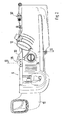
- eine Draufsicht auf das Luftfiltergehäuse,
- Fig. 3
- einen Schnitt entlang der Linie III - III in Fig. 2 und
- Fig. 4
- eine Innenansicht auf die Reinluftschale des Luftfiltergehäuses
- Fig. 1
- a schematic representation of an air filter housing with integrated resonator,
- Fig. 2
- a top view of the air filter housing,
- Fig. 3
- a section along the line III - III in Fig. 2 and
- Fig. 4
- an inside view of the clean air bowl of the air filter housing
Das in Fig. 1 schematisch dargestellte Luftfiltergehäuse 2 besteht aus einer
Rohluftschale 4 und einer Reinluftschale 6, die beide dicht miteinander verbunden sind. The
Zwischen diesen beiden Schalen 4 und 6 ist ein Luftfilter 8 angeordnet. Die Zuführung
von Rohluft LR in das Gehäuse 2 erfolgt über eine mit dem Rohluftraum 4a in Verbindung
stehende Zuleitung 10 und dann über den Luftfilter 8 in den Reinluftraum 6a und von dort
aus wird die Reinluft LM über eine Zuführleitung 12 dem Ansaugtrakt der
Brennkraftmaschine zugeführt.Between these two
In der Gehäusewand der Rohluftschale 4 ist eine Öffnung 13 eingebracht, in die ein mit
einer Gewebestruktur versehenes Einsatzteil 14 befestigt ist. Das rahmenartige
Einsatzteil 14 weist mehrere fensterartige Öffnungen 14a bis 14e auf, die von dem
technischen Gewebe überdeckt sind. Das technische Gewebe kann dabei auf dem
Einsatzteil 14 aufgespritzt, aufgeschweißt, aufgeklebt oder klemmend am Rahmen des
Einsatzteils 14 befestigt sein. Das Einsatzteil 14 wiederum kann mit Hilfe einer Schrauboder
Clipsverbindung 16 an der Reinluftschale 4 befestigt sein. Das Gewebe stellt sicher,
dass durch das Schwingen der Luftsäule im Ansaugtrakt der Brennkraftmaschine
Schallanteile nach außen geleitet werden können, verhindert aber andererseits, dass
Wasser, Schmutz oder dgl. von außen über die Öffnung 13 in das Luftfiltergehäuse 2
gelangen kann. Zu diesem Zweck kann das Gewebe wahlweise noch zusätzlich
hydrophob beschichtet werden.In the housing wall of the raw air shell 4, an
Alternativ zum Gewebe ist es auch möglich, dass die Gehäuseöffnung 13 durch ein dünnwandiges Schallelement abgedeckt ist, das gleiche oder ähnliche Eigenschaften wie das Gewebe aufweist. Das Gewebe oder das Schallelement kann dabei schwingend im Einsatzteil 14 befestigt sein. Zur weiteren Ausbildung des Gewebes bzw. des Schallelementes wird auf die EP 1 350 945 A2 verwiesen, dessen Offenbarungsgehalt ausdrücklich mit einbezogen ist.As an alternative to the tissue, it is also possible that the housing opening 13 through a thin-walled sound element is covered, the same or similar characteristics as having the tissue. The fabric or the sound element can oscillate in the process Insert 14 to be attached. For further formation of the tissue or the Schallelementes is made to EP 1 350 945 A2, the disclosure of which is explicitly included.
In der Reinluftschale 6 ist ein Resonatorgehäuse 18 integriert, dessen Volumen 20 über
einen Rohrleitungsabschnitt 22 mit der zum Ansaugtrakt der Brennkraftmaschine
führenden Zuführleitung 12 in Verbindung steht. Im Rohrleitungsabschnitt 22 ist ein
Absperrelement 24 angeordnet, das im vorliegenden Ausführungsbeispiel als Klappe
ausgebildet und in seiner geöffneten Position das Resonatorvolumen 20 mit der
Zuführleitung 12 verbindet und im geschlossenen Zustand das Resonatorvolumen 20 von
der Zuführleitung 12 und damit vom Ansaugtrakt der Brennkraftmaschine trennt. Wie aus
Fig. 3 ersichtlich, ist das Klappenelement 24 über ein Gestänge 26 mit einer
Unterdruckdose 28 verbunden. Die Unterdruckdose 28 ist über eine Druckleitung 30 mit
einem nicht dargestellten Unterdruckspeicher verbunden, wobei durch ein in der
Druckleitung 30 angeordnetes Umschaltventil 32 die Verbindung zwischen Druckdose 28
und Unterdruckspeicher zu- bzw. abschaltbar ist.In the
Das Resonatorvolumen 20 wird im unteren und mittleren Drehzahlbereich durch Schließen
der Klappe 24 vom Ansaugtrakt der Brennkraftmaschine getrennt, um die Anregung der
höheren Motorordnungen für die Schallübertragung mit einer diskreten Frequenz in den
Innenraum zu nutzen. Im oberen Drehzahlbereich wird die Klappe 24 geöffnet und somit
der Resonator aktiviert, um den nach außen tretenden Geräusch- bzw. Schallpegel
abzusenken, der in diesem Drehzahlbereich aufgrund von Resonanzerscheinungen,
angeregt durch die dominierenden Gaswechselordnungen, im Ansaugtrakt besonders
stark ausgebildet ist.The
Claims (6)
Applications Claiming Priority (2)
| Application Number | Priority Date | Filing Date | Title |
|---|---|---|---|
| DE10356583 | 2003-12-04 | ||
| DE10356583A DE10356583A1 (en) | 2003-12-04 | 2003-12-04 | Air filter for an internal combustion engine |
Publications (3)
| Publication Number | Publication Date |
|---|---|
| EP1538329A2 true EP1538329A2 (en) | 2005-06-08 |
| EP1538329A3 EP1538329A3 (en) | 2010-12-01 |
| EP1538329B1 EP1538329B1 (en) | 2014-07-09 |
Family
ID=34442432
Family Applications (1)
| Application Number | Title | Priority Date | Filing Date |
|---|---|---|---|
| EP20040026359 Expired - Fee Related EP1538329B1 (en) | 2003-12-04 | 2004-11-05 | Air filter for an internal combustion engine |
Country Status (2)
| Country | Link |
|---|---|
| EP (1) | EP1538329B1 (en) |
| DE (1) | DE10356583A1 (en) |
Cited By (1)
| Publication number | Priority date | Publication date | Assignee | Title |
|---|---|---|---|---|
| DE102017009492A1 (en) | 2017-10-12 | 2019-04-18 | Daimler Ag | Method for adjusting an engine acoustics of an internal combustion engine |
Families Citing this family (2)
| Publication number | Priority date | Publication date | Assignee | Title |
|---|---|---|---|---|
| DE102007026416B4 (en) | 2007-06-06 | 2014-09-04 | Audi Ag | Device for influencing the intake noise of an internal combustion engine |
| DE102019210078A1 (en) * | 2019-07-09 | 2021-01-14 | Mahle International Gmbh | Air filter module |
Citations (1)
| Publication number | Priority date | Publication date | Assignee | Title |
|---|---|---|---|---|
| EP1350945A2 (en) | 2002-03-27 | 2003-10-08 | Dr.Ing. h.c.F. Porsche Aktiengesellschaft | Air cleaner for an internal combustion engine |
Family Cites Families (4)
| Publication number | Priority date | Publication date | Assignee | Title |
|---|---|---|---|---|
| US4538556A (en) * | 1983-07-11 | 1985-09-03 | Toyota Jidosha Kabushiki Kaisha | Air intake device of an internal combustion engine |
| JPS6161910A (en) * | 1984-08-31 | 1986-03-29 | Nippon Denso Co Ltd | Air cleaner for internal-combustion engine |
| JP2564867B2 (en) * | 1987-12-26 | 1996-12-18 | 日本電装株式会社 | Silencer for internal combustion engine |
| JP3846569B2 (en) * | 2002-03-29 | 2006-11-15 | 株式会社デンソー | Intake device |
-
2003
- 2003-12-04 DE DE10356583A patent/DE10356583A1/en not_active Withdrawn
-
2004
- 2004-11-05 EP EP20040026359 patent/EP1538329B1/en not_active Expired - Fee Related
Patent Citations (1)
| Publication number | Priority date | Publication date | Assignee | Title |
|---|---|---|---|---|
| EP1350945A2 (en) | 2002-03-27 | 2003-10-08 | Dr.Ing. h.c.F. Porsche Aktiengesellschaft | Air cleaner for an internal combustion engine |
Cited By (1)
| Publication number | Priority date | Publication date | Assignee | Title |
|---|---|---|---|---|
| DE102017009492A1 (en) | 2017-10-12 | 2019-04-18 | Daimler Ag | Method for adjusting an engine acoustics of an internal combustion engine |
Also Published As
| Publication number | Publication date |
|---|---|
| EP1538329A3 (en) | 2010-12-01 |
| DE10356583A1 (en) | 2005-07-07 |
| EP1538329B1 (en) | 2014-07-09 |
Similar Documents
| Publication | Publication Date | Title |
|---|---|---|
| EP1350945B1 (en) | Air cleaner for an internal combustion engine | |
| DE102008005085B4 (en) | Adjustable Helmholtz resonator arrangement | |
| DE102011107677B4 (en) | vehicle seat | |
| DE4017074A1 (en) | PRESSURE CONTROL VALVE FOR THE CRANKCASE VENTILATION ON AN INTERNAL COMBUSTION ENGINE | |
| WO2001081734A1 (en) | Automotive exhaust silencer system with variable damping characteristics | |
| DE112015003965B4 (en) | fuel supply device | |
| WO2018077348A1 (en) | Device for distributing washing water, comprising a multi-valve | |
| DE102012000806A1 (en) | Resonator system for noise reduction of air filter system of gas inlet system of engine of motor vehicle, has housing and insertion part, where housing is designed such that its inner portion is designed as hollow space | |
| DE102008002314A1 (en) | Sound quality control device for an internal combustion engine | |
| DE10042012A1 (en) | Appliance for simulating sound characteristic of engine load in car interior uses vibrating membrane to convert exhaust gas pulsations into sound waves | |
| DE102005021797B4 (en) | Intake system of a multi-cylinder engine | |
| DE102006058326B4 (en) | Variable intake system of a vehicle | |
| EP1649918B1 (en) | Cleaning device for dust-removing filters | |
| EP1538329B1 (en) | Air filter for an internal combustion engine | |
| DE102005052340B4 (en) | Crankcase pressure control valve with a curved neck | |
| DE102007026416B4 (en) | Device for influencing the intake noise of an internal combustion engine | |
| EP0569714A1 (en) | Air intake device for an internal combustion engine | |
| EP0685032A1 (en) | Fuel-tank ventilation process and installation. | |
| DE10304028A1 (en) | Air filter for an internal combustion engine | |
| DE19843772A1 (en) | Suction system for an internal combustion engine | |
| DE102012010690B4 (en) | Automotive seat | |
| EP1172547B1 (en) | Intake system for a vehicle | |
| DE10062472C1 (en) | Exhaust system of a motor vehicle | |
| DE10213604A1 (en) | Air filter for an internal combustion engine | |
| DE10240473A1 (en) | Air intake system for internal combustion engine has filter element cavity bounded by two endface apertures, one monitored by closing element |
Legal Events
| Date | Code | Title | Description |
|---|---|---|---|
| PUAI | Public reference made under article 153(3) epc to a published international application that has entered the european phase |
Free format text: ORIGINAL CODE: 0009012 |
|
| AK | Designated contracting states |
Kind code of ref document: A2 Designated state(s): AT BE BG CH CY CZ DE DK EE ES FI FR GB GR HU IE IS IT LI LU MC NL PL PT RO SE SI SK TR |
|
| AX | Request for extension of the european patent |
Extension state: AL HR LT LV MK YU |
|
| RAP1 | Party data changed (applicant data changed or rights of an application transferred) |
Owner name: DR. ING. H.C. F. PORSCHE AKTIENGESELLSCHAFT |
|
| RAP1 | Party data changed (applicant data changed or rights of an application transferred) |
Owner name: DR. ING. H.C. F. PORSCHE AKTIENGESELLSCHAFT |
|
| RAP1 | Party data changed (applicant data changed or rights of an application transferred) |
Owner name: DR. ING. H.C. F. PORSCHE AG |
|
| PUAL | Search report despatched |
Free format text: ORIGINAL CODE: 0009013 |
|
| AK | Designated contracting states |
Kind code of ref document: A3 Designated state(s): AT BE BG CH CY CZ DE DK EE ES FI FR GB GR HU IE IS IT LI LU MC NL PL PT RO SE SI SK TR |
|
| AX | Request for extension of the european patent |
Extension state: AL HR LT LV MK YU |
|
| RIC1 | Information provided on ipc code assigned before grant |
Ipc: F02B 27/02 20060101ALI20101025BHEP Ipc: F02M 35/14 20060101AFI20050413BHEP |
|
| 17P | Request for examination filed |
Effective date: 20110601 |
|
| AKX | Designation fees paid |
Designated state(s): DE FR GB IT |
|
| 17Q | First examination report despatched |
Effective date: 20111019 |
|
| GRAP | Despatch of communication of intention to grant a patent |
Free format text: ORIGINAL CODE: EPIDOSNIGR1 |
|
| INTG | Intention to grant announced |
Effective date: 20140128 |
|
| GRAS | Grant fee paid |
Free format text: ORIGINAL CODE: EPIDOSNIGR3 |
|
| GRAA | (expected) grant |
Free format text: ORIGINAL CODE: 0009210 |
|
| AK | Designated contracting states |
Kind code of ref document: B1 Designated state(s): DE FR GB IT |
|
| REG | Reference to a national code |
Ref country code: GB Ref legal event code: FG4D Free format text: NOT ENGLISH |
|
| REG | Reference to a national code |
Ref country code: DE Ref legal event code: R096 Ref document number: 502004014673 Country of ref document: DE Effective date: 20140814 |
|
| REG | Reference to a national code |
Ref country code: DE Ref legal event code: R097 Ref document number: 502004014673 Country of ref document: DE |
|
| PG25 | Lapsed in a contracting state [announced via postgrant information from national office to epo] |
Ref country code: IT Free format text: LAPSE BECAUSE OF FAILURE TO SUBMIT A TRANSLATION OF THE DESCRIPTION OR TO PAY THE FEE WITHIN THE PRESCRIBED TIME-LIMIT Effective date: 20140709 |
|
| PLBE | No opposition filed within time limit |
Free format text: ORIGINAL CODE: 0009261 |
|
| STAA | Information on the status of an ep patent application or granted ep patent |
Free format text: STATUS: NO OPPOSITION FILED WITHIN TIME LIMIT |
|
| 26N | No opposition filed |
Effective date: 20150410 |
|
| REG | Reference to a national code |
Ref country code: FR Ref legal event code: PLFP Year of fee payment: 12 |
|
| REG | Reference to a national code |
Ref country code: FR Ref legal event code: PLFP Year of fee payment: 13 |
|
| REG | Reference to a national code |
Ref country code: FR Ref legal event code: PLFP Year of fee payment: 14 |
|
| PGFP | Annual fee paid to national office [announced via postgrant information from national office to epo] |
Ref country code: FR Payment date: 20181123 Year of fee payment: 15 Ref country code: GB Payment date: 20181120 Year of fee payment: 15 |
|
| PGFP | Annual fee paid to national office [announced via postgrant information from national office to epo] |
Ref country code: DE Payment date: 20191024 Year of fee payment: 16 |
|
| GBPC | Gb: european patent ceased through non-payment of renewal fee |
Effective date: 20191105 |
|
| PG25 | Lapsed in a contracting state [announced via postgrant information from national office to epo] |
Ref country code: GB Free format text: LAPSE BECAUSE OF NON-PAYMENT OF DUE FEES Effective date: 20191105 Ref country code: FR Free format text: LAPSE BECAUSE OF NON-PAYMENT OF DUE FEES Effective date: 20191130 |
|
| REG | Reference to a national code |
Ref country code: DE Ref legal event code: R119 Ref document number: 502004014673 Country of ref document: DE |
|
| PG25 | Lapsed in a contracting state [announced via postgrant information from national office to epo] |
Ref country code: DE Free format text: LAPSE BECAUSE OF NON-PAYMENT OF DUE FEES Effective date: 20210601 |