EP1523691B1 - Zoom lens system with ultra high zoom ratio - Google Patents
Zoom lens system with ultra high zoom ratio Download PDFInfo
- Publication number
- EP1523691B1 EP1523691B1 EP03765693A EP03765693A EP1523691B1 EP 1523691 B1 EP1523691 B1 EP 1523691B1 EP 03765693 A EP03765693 A EP 03765693A EP 03765693 A EP03765693 A EP 03765693A EP 1523691 B1 EP1523691 B1 EP 1523691B1
- Authority
- EP
- European Patent Office
- Prior art keywords
- optical
- zoom lens
- lens system
- zoom
- image
- Prior art date
- Legal status (The legal status is an assumption and is not a legal conclusion. Google has not performed a legal analysis and makes no representation as to the accuracy of the status listed.)
- Expired - Lifetime
Links
- 230000003287 optical effect Effects 0.000 claims abstract description 187
- 230000006641 stabilisation Effects 0.000 claims abstract description 23
- 238000011105 stabilization Methods 0.000 claims abstract description 23
- 230000008859 change Effects 0.000 claims abstract description 21
- 230000033001 locomotion Effects 0.000 claims description 23
- 210000001747 pupil Anatomy 0.000 claims description 18
- 238000003384 imaging method Methods 0.000 claims description 9
- 230000005855 radiation Effects 0.000 claims description 8
- 230000000087 stabilizing effect Effects 0.000 claims 1
- 150000001875 compounds Chemical class 0.000 description 27
- 238000010586 diagram Methods 0.000 description 27
- 230000004075 alteration Effects 0.000 description 26
- 239000011521 glass Substances 0.000 description 23
- 238000013461 design Methods 0.000 description 11
- 239000006185 dispersion Substances 0.000 description 7
- 229910052732 germanium Inorganic materials 0.000 description 7
- GNPVGFCGXDBREM-UHFFFAOYSA-N germanium atom Chemical compound [Ge] GNPVGFCGXDBREM-UHFFFAOYSA-N 0.000 description 7
- XZKIHKMTEMTJQX-UHFFFAOYSA-N 4-Nitrophenyl Phosphate Chemical compound OP(O)(=O)OC1=CC=C([N+]([O-])=O)C=C1 XZKIHKMTEMTJQX-UHFFFAOYSA-N 0.000 description 6
- 230000008901 benefit Effects 0.000 description 6
- 238000012937 correction Methods 0.000 description 6
- 238000013459 approach Methods 0.000 description 4
- 238000010276 construction Methods 0.000 description 4
- 230000000694 effects Effects 0.000 description 4
- 238000012986 modification Methods 0.000 description 4
- 230000004048 modification Effects 0.000 description 4
- 101000596093 Homo sapiens Transcription initiation factor TFIID subunit 1 Proteins 0.000 description 3
- 102100035222 Transcription initiation factor TFIID subunit 1 Human genes 0.000 description 3
- 230000006870 function Effects 0.000 description 3
- 239000005331 crown glasses (windows) Substances 0.000 description 2
- 230000006866 deterioration Effects 0.000 description 2
- 238000004519 manufacturing process Methods 0.000 description 2
- 239000000463 material Substances 0.000 description 2
- 238000000034 method Methods 0.000 description 2
- 230000011514 reflex Effects 0.000 description 2
- 238000012546 transfer Methods 0.000 description 2
- 239000004606 Fillers/Extenders Substances 0.000 description 1
- VMXJCRHCUWKQCB-UHFFFAOYSA-N NPNP Chemical compound NPNP VMXJCRHCUWKQCB-UHFFFAOYSA-N 0.000 description 1
- 230000002159 abnormal effect Effects 0.000 description 1
- 238000005452 bending Methods 0.000 description 1
- 230000009286 beneficial effect Effects 0.000 description 1
- WUKWITHWXAAZEY-UHFFFAOYSA-L calcium difluoride Chemical compound [F-].[F-].[Ca+2] WUKWITHWXAAZEY-UHFFFAOYSA-L 0.000 description 1
- 229910001634 calcium fluoride Inorganic materials 0.000 description 1
- 238000013329 compounding Methods 0.000 description 1
- 230000003247 decreasing effect Effects 0.000 description 1
- 239000000428 dust Substances 0.000 description 1
- 238000004880 explosion Methods 0.000 description 1
- 238000003780 insertion Methods 0.000 description 1
- 230000037431 insertion Effects 0.000 description 1
- 238000005259 measurement Methods 0.000 description 1
- 239000005304 optical glass Substances 0.000 description 1
- 230000003534 oscillatory effect Effects 0.000 description 1
- 230000009467 reduction Effects 0.000 description 1
- 238000009877 rendering Methods 0.000 description 1
- 230000029058 respiratory gaseous exchange Effects 0.000 description 1
- 230000004044 response Effects 0.000 description 1
- 238000007789 sealing Methods 0.000 description 1
- 239000007787 solid Substances 0.000 description 1
- 238000003860 storage Methods 0.000 description 1
- 238000006467 substitution reaction Methods 0.000 description 1
Images


Classifications
-
- G—PHYSICS
- G02—OPTICS
- G02B—OPTICAL ELEMENTS, SYSTEMS OR APPARATUS
- G02B15/00—Optical objectives with means for varying the magnification
- G02B15/02—Optical objectives with means for varying the magnification by changing, adding, or subtracting a part of the objective, e.g. convertible objective
- G02B15/10—Optical objectives with means for varying the magnification by changing, adding, or subtracting a part of the objective, e.g. convertible objective by adding a part, e.g. close-up attachment
- G02B15/12—Optical objectives with means for varying the magnification by changing, adding, or subtracting a part of the objective, e.g. convertible objective by adding a part, e.g. close-up attachment by adding telescopic attachments
-
- G—PHYSICS
- G02—OPTICS
- G02B—OPTICAL ELEMENTS, SYSTEMS OR APPARATUS
- G02B15/00—Optical objectives with means for varying the magnification
- G02B15/14—Optical objectives with means for varying the magnification by axial movement of one or more lenses or groups of lenses relative to the image plane for continuously varying the equivalent focal length of the objective
- G02B15/142—Optical objectives with means for varying the magnification by axial movement of one or more lenses or groups of lenses relative to the image plane for continuously varying the equivalent focal length of the objective having two groups only
-
- G—PHYSICS
- G02—OPTICS
- G02B—OPTICAL ELEMENTS, SYSTEMS OR APPARATUS
- G02B27/00—Optical systems or apparatus not provided for by any of the groups G02B1/00 - G02B26/00, G02B30/00
- G02B27/64—Imaging systems using optical elements for stabilisation of the lateral and angular position of the image
- G02B27/646—Imaging systems using optical elements for stabilisation of the lateral and angular position of the image compensating for small deviations, e.g. due to vibration or shake
-
- G—PHYSICS
- G02—OPTICS
- G02B—OPTICAL ELEMENTS, SYSTEMS OR APPARATUS
- G02B13/00—Optical objectives specially designed for the purposes specified below
- G02B13/14—Optical objectives specially designed for the purposes specified below for use with infrared or ultraviolet radiation
Definitions
- This invention relates to optical lens systems for cameras and other optical devices, and, in particular, to high performance zoom lens systems that produce a high quality image over a full zoom range of focal lengths and are capable of being provided with an extremely large zoom ratio.
- zoom lens systems for all types of photography, such as broadcast television, high definition television (“HDTV”), advanced television (“ATV”), video camcorders, film cinematography and still photography has become increasingly popular.
- high definition television high definition television
- ATV advanced television
- video camcorders video camcorders
- film cinematography still photography
- zoom lens systems As the use of zoom lens systems has increased, the demand for wider ranges of zooming capability, i.e. large zoom ratios, has also increased.
- the zoom lens systems used in broadcast television have steadily increased in zoom ratio capability over the years to a maximum of about 101 to 1 at present but there is a demand for a still larger zoom ratio.
- a conventional zoom lens system may be increased by the use of a drop-in extender or other multiplier, such as a broadcast television zoom lens system with a focal length range of 8.9mm to 900mm being increased to 17.8mm to 1800mm to increase the telephoto capability, this does not change the zoom ratio of about 101 to 1.
- a drop-in extender or other multiplier such as a broadcast television zoom lens system with a focal length range of 8.9mm to 900mm being increased to 17.8mm to 1800mm to increase the telephoto capability
- zoom lens systems with wider ranges of focal lengths
- such lenses must retain superior optical characteristics and performance that previously has been accomplished only by using separate objective lenses of different fixed focal lengths or zoom lens systems with a limited zoom ratio.
- the difficulty in providing a high performance optical system with superior characteristics and performance also increases.
- Even most previously available zoom lens systems of a limited zoom range have one or more undesirable limitations such as the inability to focus adequately over the entire focal length range, the inability to focus on close objects, the lack of adequate optical performance over the entire focal length range and focus distance, the cost, the large size for the limited zoom range achieved and the like.
- zoom lens systems with a wide-range of focal lengths are very desirable in numerous photographic applications, including broadcast television, cinematography and video and still photography.
- One standard zoom lens system used in these applications has a four-group PN(P or N)P structure, where P stands for a group of at least one lens element wherein the lens group has positive power, N stands for a group of at least one lens element wherein the lens group has negative power, and the groups are identified consecutively from the object space toward the image space, as is conventional.
- the front positive group is often called the focusing group because it can be moved for focusing the zoom lens system at any focal length position without the need to refocus for any other focal length of the zoom lens.
- the second negative group is the variator, and it induces significant magnification change during zooming.
- the third group which can in general have either positive or negative power, is the compensator, and it is movable to insure that the image plane remains stationary. It also can provide some of the magnification change to effect zooming.
- the final positive fourth group is often called the prime lens group because it forms a sharp image.
- This basic zoom lens system is suitable for zoom ratios of 50:1 or even more.
- the variator is required to change its object magnification to such an extent during zooming that aberrations become impracticably large and difficult to correct.
- there is a very large change in entrance pupil location during zooming and this tends to make the front group very large and difficult to correct.
- Another problem derives from the fact that, to reduce the aberration change that results from a large change of magnification, it is desirable that the variator have reduced optical powers. Weaker optical power, however, also increases the lens travel and length of the optical system.
- US 3,970,366 discloses a highly variable magnification zoom lens system in which a first zoom lens is connected from an object side and then a second zoom lens is connected from behind said first zoom lens. Therein, a first diaphragm for determining the relative aperture of the total zoom lens system is provided between said first zoom lens and the second zoom lens.
- a zoom lens system that overcomes the problems and inefficiencies of prior zoom lens systems having large zoom ratios.
- a further object is to provide a zoom lens system with a wide zoom range of focal lengths and high performance characteristics for both indoor and outdoor use.
- a still further object of this invention is to provide a zoom lens system with a ratio of about 300 to 1 and a zoom range, for example, from about 7mm to 2100mm focal length, with continuous zooming between the focal lengths.
- Still another object of this invention is to provide a high performance zoom lens system with an optical system having a front zoom lens group for forming an intermediate image and a rear zoom lens group to magnify that image to thereby produce an extremely large zoom ratio.
- Still another object is to provide such a zoom lens system with optical image stabilization.
- Still another object is to provide such a zoom lens system with a focusing lens group capable of precise focusing over the entire focal length range of the zoom ratio.
- the zoom lens systems of the invention can have conventional zoom ratios, e.g., zoom ratios associated with such consumer products as video camcorders, still cameras and the like. It is an additional object of the invention to produce zoom lens systems for these smaller zoom ratio applications.
- the present invention overcomes the obstacles that currently limit zoom lens systems to a zoom ratio of about 101:1.
- the basic idea of the invention can be viewed as the use of a compound zoom lens system that consists of two separate zoom lens portions wherein the front zoom lens portion forms an intermediate image, and the rear zoom lens portion is a relay that transfers the intermediate image formed by the front zoom lens portion to the final image.
- the total zoom ratio of the complete compound zoom lens system is equal to the zoom ratio of the front zoom lens multiplied by the zoom ratio of the relay.
- the zoom ratio of the front zoom lens portion is 20:1 and the zoom ratio of the relay is 15:1, then the zoom ratio of the entire compound zoom lens system is 300:1.
- the present invention can be used to achieve a zoom ratio of 300:1 or more, which greatly exceeds the practical limit of conventional zoom lens systems.
- the invention provides a zoom lens system for forming a final image of an object, said system forming a first intermediate real image between the object and the final image, said system comprising:
- the zoom lens system includes one or more optical subunits in either or both of the first and second optical units which is moved to hold the axial position of the final image substantially stationary as the focal length of the system is changed (e.g., lens elements 12 through 15 are the primary source of this function in Figure 10).
- Such a subunit may not be needed in all cases, e.g., if the overall optical system has an axially movable sensor.
- the zoom lens system comprises a focus unit (e.g., lens elements 1 through 7 in Figure 10), a pupil imaging unit (e.g., lens elements 16 through 25 in Figure 10), and/or an image stabilization unit (e.g., lens elements 34 through 39 in Figure 10).
- a focus unit e.g., lens elements 1 through 7 in Figure 10
- a pupil imaging unit e.g., lens elements 16 through 25 in Figure 10
- an image stabilization unit e.g., lens elements 34 through 39 in Figure 10.
- the focus unit is (1) positioned in front of the first optical unit, (2) comprises two optical subunits that are movable along the zoom lens system's optical axis (e.g., lens element 2 and elements 3 and 4 in Figure 10), and/or (3) comprises seven or less lens elements.
- the image stabilization unit comprises (1) at least one lens element that is laterally movable off the system's optical axis (e.g., lens elements 34 through 36 in Figure 10), and/or (2) at least one lens element that is movable along the optical axis (e.g., lens elements 37 through 39 in Figure 10).
- the light passing through the system is preferably substantially collimated between said laterally and axially movable lens elements of the image stabilization unit.
- the zoom lens systems of the invention can form additional intermediate real images between the object and the final image.
- the systems can include additional optical units besides the first and second units for changing the sizes (magnifications) of those additional intermediate real images.
- the first intermediate real image is formed in an air space between the optical elements of the zoom lens system (e.g., the lens elements, prisms, folding mirrors or the like used in the system) and does not pass through any surface of an optical element during zooming.
- the optical elements of the zoom lens system e.g., the lens elements, prisms, folding mirrors or the like used in the system
- this is also preferably true for all of the intermediate images.
- the first optical unit in combination with other units of the system can have the form of a conventional zoom lens.
- the second optical unit in combination with other units of the system can have a conventional zoom lens form.
- the overall system can thus be viewed as a "compounding" of two conventional zoom lenses with, in accordance with the invention, control of pupil imaging between the compounded zoom lenses.
- the overall system can also be viewed as a front zoom lens which forms an intermediate image and a relay system which receives the intermediate image and changes its magnification to form the final image.
- the invention provides a zoom lens system for forming a final image of an object, said system having a range of focal lengths between a maximum focal length and a minimum focal length and forming at least a first intermediate real image between the object and the final image for all focal lengths within said range, said system comprising:
- the invention provides a zoom lens system which comprises a variable focal length front lens unit which forms an intermediate real image and a variable magnification rear lens unit which forms an image (preferably, a real image) of the intermediate image.
- the invention provides a compound zoom lens system that collects radiation from an object space and delivers the radiation to a final image in image space, said system comprising multiple zoom lens portions including a first zoom lens portion forming an intermediate image of the radiation from the object space and a last zoom lens portion forming the final image in the image space.
- the invention provides a zoom lens system for forming a final image of an object, said system having an optical axis, a front lens surface, an aperture stop, and a chief ray which crosses the optical axis at the aperture stop, said system comprising first and second lens units that are moved to change the focal length of the system, wherein:
- the front zoom lens portion is stationary at its long focal length position, and the relay then zooms to magnify the intermediate image to a greater and greater extent.
- the image NA of the relay becomes smaller and the object NA of the relay becomes larger.
- the image NA of the front zoom lens portion must also become larger.
- the radial part of the intermediate image that is actually used becomes smaller and smaller as the system focal length gets larger.
- the front zoom lens portion need not be corrected for a simultaneously large intermediate image size and a large relative aperture (NA). Rather, it needs to be corrected for a large intermediate image size at a small aperture, and for a small intermediate image size at a large aperture.
- NA relative aperture
- the relay need only be corrected for a large image NA and large object size at the small magnification end of its focal lengths.
- the object size is small and the image NA is also small.
- the zoom lens systems of the invention preferably also include a pupil imaging unit.
- This unit serves to image the exit pupil of the front zoom lens portion into the entrance pupil of the relay.
- the intermediate image formed by the front zoom lens portion is preferably located at a position where it does not pass through any lens surfaces as the system is zoomed from its minimum to its maximum focal lengths.
- the intermediate image is automatically behind the axially moving lens unit or units that provide zooming in the front zoom lens portion and in front of any axially moving lens units that provide zooming in the rear zoom portion. Since in certain embodiments of the invention the intermediate image can move during zooming, the locations for the lens surfaces on either side of the intermediate image, whether those surfaces are fixed or moving, are preferably chosen so that notwithstanding.the motion of the intermediate image, the surfaces remain spaced from the intermediate image throughout the zoom range of the system.
- Figures 1-3 for a PNPP - PNPP compound zoom lens system with a zoom ratio of about 300:1.
- this compound zoom lens system has a front zoom lens portion with a zoom ratio of about 20:1 and a rear zoom lens portion (relay) with a zoom ratio of about 15:1.
- the groups and their positive or negative power signs are also indicated in Figure 1.
- the relay is stationary as the front zoom lens portion is operated from its shortest focal length position (shown in Figure 1) to its longest focal length position (shown in Figure 2). Once the front zoom lens portion reaches its long focal length position, the relay begins to vary the magnification of the intermediate image to further increase the focal length of the compound system.
- Figure 3 shows the system in its maximum focal length condition, in which the front zoom lens portion is at its maximum focal length position and the rear zoom (relay) lens portion is in its maximum magnification position.
- Figures 1 and 2 show the small NA at the intermediate image plane and large NA at the final image plane that occurs during the initial phase of zooming from short to long.
- the size of the intermediate image is large during this phase, as shown in the figures.
- Figure 3 shows that the NA becomes larger at the intermediate image and smaller at the final image at the longest focal length position.
- zoom lens groups there are 8 zoom lens groups, but only 4 of them are independently movable for zooming.
- the 1 st, 4th, 5th, and 8th groups are all stationary with respect to the final image. During focusing, however, one or more of these groups can be made to move.
- the zooming motion need not be clearly divided into two stages, and as a result the relay or a part of it can move during the initial zooming stages and not just near the long end of the focal lengths.
- Figs. 1-3 has a PNPP - PNPP construction in which the dash "-" signifies the end of the front zoom lens portion.
- Both the front zoom lens portion and rear zoom lens portion have variator and compensator zooming groups.
- One advantage of this configuration is that the intermediate image can be made absolutely stationary if desired. Rendering the image stationary will prevent it from passing through any optical surface that might reveal surface flaws and dust images that will appear at the final image.
- Using a four-group construction in the rear zoom lens portion also permits better control of the exit pupil position, which may be important for matching the telecentricity requirements of certain image sensors.
- an eyepiece-like group is beneficial for converting the diverging beams emanating from the intermediate image into approximately parallel beams entering a normal PNP- or PNPP- type zoom lens system corrected for infinite conjugates.
- diffractive surfaces can be used in the practice of the invention.
- diffractive optical elements of the type disclosed in U.S. Patent No. 6,507,437, assigned to Canon, can be used, either alone or in combination with other approaches for correcting chromatic aberrations.
- both the front zoom lens portion and the rear zoom lens portion (relay) system can have very large zoom ratios. It is quite reasonable to have a zoom ratio of 20:1 or more for either the front zoom lens portion or the rear zoom lens portion in this case, so that a total zoom ratio of 400:1 or more is possible. However, if such a large zoom ratio is not required, it is possible to simplify the system significantly by instead using a relay with an NP configuration having two moving groups. Such a relay is very useful for large aperture applications with a total zoom ratio in the relay of about 3:1 to about 10:1.
- FIG. 4A illustrates the minimum focal length of about 7mm and Fig. 4B illustrates the maximum focal length of about 900mm.
- Fig. 4A illustrates the minimum focal length of about 7mm and Fig. 4B illustrates the maximum focal length of about 900mm.
- the rearmost lens group is not stationary; hence it must be designed to withstand a considerable change of magnification at large apertures, which makes it somewhat difficult to design.
- an even further simplified construction consisting of an NP front zoom lens portion and an NP rear zoom lens portion (relay) can also be designed, although the maximum zoom ratio in this case will be lowered.
- the technique can be generalized to include a large number of combinations of various zoom lens arrangements for the front zoom lens portion and for the rear zoom lens portion.
- a high zoom ratio, ultra wide angle zoom lens system can be constructed by using an NP, NPP or NPNP ultra wide angle front zoom lens portion having a zoom ratio of about 2:1 with an NP rear zoom lens portion (relay) having a zoom ratio of about 6.5:1.
- the result would be a compound zoom lens system with a zoom ratio of about 13:1 with a maximum full field of view of up to 100 degrees or more.
- 5A and 5B illustrate a 4.4mm-57.2mm, f/3-f/7 compound zoom lens system with a zoom ratio of about 13:1 for a 2/3" sensor.
- the full-field angle at the wide-angle end of this compound zoom lens system is more than 102 degrees.
- a PNPP-type rear zoom lens portion (relay) similar to the one used in Figs. 1-3 could be used with this same ultra wide angle front zoom lens portion to yield an ultra wide angle compound zoom lens system with a zoom ratio of about 30:1.
- an intermediate image is common to all of these configurations, and this offers some unique opportunities for aberration correction that are not typically available in zoom lens system types of the prior art.
- aspheric surfaces placed on elements located near the intermediate image can have a strong impact on distortion and other field aberrations without disturbing the spherical aberration correction.
- Advantages of placing an aspheric surface in this area include that the tolerances are generous because the beam diameters are small, and the elements themselves are small. This means that the cost of using aspheric surfaces in this region is minimal.
- each of the herein disclosed embodiments of the present invention includes a front zoom lens portion and a rear zoom lens portion thereby forming a compound zoom lens system.
- An intermediate image is formed after the front zoom lens portion whereby the rear zoom lens portion functions as a zoom relay to magnify the intermediate image so as to produce the magnified final image for capturing by film or any other kind of light detector or capture device, such as a charge coupled device (CCD), in a camera.
- CCD charge coupled device
- the term "camera” is used generically to describe any kind of light detecting or capturing device that may be placed after the lens system of the present invention, including a still, video or movie capture device, whether containing film, videotape, optical disk, CMOS, CCD or another storage medium, or an eyepiece or the human eye. Any such "camera” may include additional lens elements.
- the front zoom lens portion will be comprised of two moving zoom lens groups and the rear zoom lens portion will be comprised of either one or two moving zoom lens groups, but it is to be understood that more or fewer moving zoom lens groups may be used without departing from the present invention.
- only one intermediate image will be formed in the entire compound zoom lens system but other embodiments of the present invention may form more than one intermediate image.
- the compound zoom lens system of the present invention preferably includes a focus lens group. It is preferred that the focus lens group be positioned at the front of the lens system, as shown by each of the embodiments disclosed herein, although it is possible to accomplish some and maybe all of the focusing elsewhere in the compound zoom lens system in other embodiments of the invention.
- Still another solution to the orientation problem for a video camera that uses a "frame store" feature to store an entire frame on a memory chip before it is transmitted for use is to merely transmit the stored frame from the frame store memory in the reverse order.
- the entire camera with the film magazine may be turned upside down to, as a result, run the film upwardly for correcting the image orientation.
- Another solution for the orientation of the image in a movie film camera used in the conventional manner and employing the present zoom lens system is to use digital compositing wherein the film is digitally scanned and then, for example, after digital manipulation the image is imposed on new film in the conventional orientation.
- the use of a prism in or in connection with the lens system of this invention will also correct the orientation of the final image. For this approach, care must be taken so that the prism will not cause excessive deterioration of the quality of the final image, especially for high performance applications of the present lens system.
- the body of the compound lens system will often be of substantial length and therefore any deflection or vibration of the lens system relative to the camera may cause unacceptable deflection or vibration of the final image in the camera.
- an image stabilization arrangement will be employed. While electronic image stabilization may be appropriate for some video camera applications, for higher performance zoom lens system applications it is preferred that an optical image stabilization arrangement be included in the body of the compound zoom lens system and preferably near the camera end of the lens system, such as is included in the embodiment of Figs. 10-62 described below.
- the compound zoom lens system of this invention may be used as an integral unit for maximum performance
- two or more separable components may be used as the front zoom lens portion and then the rear zoom lens portion may be comprised of a separate attachment that relays and varies the magnification of (e.g. zooms) the image formed by the front zoom lens portion, which image becomes the "intermediate" image, to form the final image.
- the front zoom lens portion will provide one zoom ratio and the rear attachment zoom portion will provide another zoom ratio.
- the pupil imaging should be controlled to obtain a final image of acceptable optical quality.
- Other such combinations of conventional and/or modified lens portions may also be used to provide the compound zoom lens system of the present invention.
- Figs. 6A through 9B illustrate optical diagrams for four different embodiments of the zoom lens system of the present invention.
- the two rectangular blocks represent the prism blocks for a conventional 3 CCD 2/3" detector, which is part of the video camera and therefore not part of the zoom lens system.
- the following tables list the lens system optical prescriptions, the variable thickness positions for various surfaces, and the focal lengths and magnifications for various surface groups for each of those four embodiments. For simplicity and clarity in view of the large number of surfaces and the small scale of the optical diagrams that include all of the elements, only some of the surfaces in Figs. 6A through 9B that correspond to the surfaces set forth in the lens system optical prescriptions are identified. A more detailed explanation of the tables is provided following the tables. TABLES FOR FIGS.
- each surface of a lens element identified in the left hand column (“Surface”), the radius of that surface in the second column (“Radius”), the thickness on the optical axis between that surface and the next surface, whether glass or air, in the third column (“Thickness”), the refractive indices of the glass lens elements set forth in the fourth column (“Glass Index”), and the dispersion values for the lens elements (“Glass Dispersion”) set forth in the fifth column.
- the surface numbers in the first column “Surface” represent the surfaces numbered from left-to-right in the Figs. in the conventional manner, namely from object space to image space.
- the object to be imaged e.g., photographed
- the adjustable iris or stop is identified as “STOP”
- the final image is identified as "IMAGE”.
- the adjustable spaces between lens elements, such as on either side of movable zoom groups are identified as “Variable” in the third or Thickness column of the lens system optical prescription.
- the EFL, Radius and Thickness dimensions are given in millimeters with the Thickness being the distance after that surface on the optical axis.
- Aspheric Coefficients for each of the aspheric surfaces are provided following the table of optical prescriptions.
- tables of the variable thickness positions for various surfaces in each lens system optical prescription are provided which identify positions in the format "Px" for various surfaces (corresponding to entries in the Surface column of the optical prescription tables).
- the effective focal length (EFL) and the "f" number (F/No.) are also provided for each position.
- FIG. 6A and 6B has an effective focal length range of about 7.25mm to 900mm, which provides a zoom ratio of about 125:1, while using three movable zoom lens groups, namely, Zoom 1, Zoom 2, and Zoom 3, with a focus lens group Focus at the object space end of the lens.
- the Zoom 3 group actually is comprised of two groups of elements that have a small amount of movement between surfaces S47 and S48 (compare Figs. 6A and 6B).
- FIG. 7A and 7B has an effective focal length range of about 7.27mm to 2088mm, which provides a zoom ratio of about 287:1, with four movable zoom lens groups (Zoom 1, 2, 3 and 4) and a focus lens group.
- the embodiment of Figs. 8A and 8B has an effective focal length range of about 7.27mm to 2095mm, which also provides a zoom range of about 287:1, with four moving zoom lens groups and a focus lens group, which is very similar to the performance of the lens embodiment of Figs. 7A and 7B.
- the embodiment of Figs. 9A and 9B has an effective focal length range of about 7.27mm to 2092mm, which also provides a zoom ratio of about 287:1, but uses only three moving zoom lens groups.
- Each of these four embodiments includes plural aspheric surfaces with the embodiments of the Figs. 8A-8B and 9A-9B having only two such surfaces while the embodiment of Figs. 7A-7B includes eight such surfaces, as indicated in the lens system optical prescriptions.
- the embodiment of Figs. 9A and 9B also includes optical image stabilization lens elements near the camera end of the lens system similar to those included in the embodiment of Figs. 10-62, which will be described below.
- Figs. 10-62 all relate to a single embodiment of the present invention that is directly and immediately applicable to the broadcast television market, although other markets are also available and various other embodiments and modifications of the invention may be more applicable to other markets.
- This embodiment of the compound zoom lens system of this invention has a zoom range of approximately 7 mm to 2100 mm in focal length, thereby providing a zoom ratio of about 300:1, which is more than three times the zoom ratio presently available in broadcast television zoom lens systems. Referring more particularly to the optical diagram of Fig.
- the zoom lens system ZL is comprised of a focus lens group FG, a front zoom group FZG and a rear zoom group RZG.
- the lens system's stop is used as a divider between the "front” and “rear” of the lens.
- the focus lens group FG is the focus unit
- the front zoom group FZG is the first optical unit
- the rear zoom group RZG includes a pupil imaging unit and an image stabilization unit, as well as the second optical unit.
- the focus group FG is comprised of seven lens elements 1-7 with the front lens element 1 being stationary whereby the lens may be sealed at the front by fixing and sealing element 1 to the lens barrel (not shown).
- Lens element 2 comprises a first focus group FG1 and lens elements 3 and 4 comprise a second focus group FG2, both of which groups are independently movable for achieving the desired focus at each focal length.
- Elements 5-7 of the focus group FG are stationary.
- the front zoom group FZG has a first zoom group ZG1 comprised of lens elements 8-11 and a second zoom group ZG2 comprised of lens elements 12-15, both of which zoom groups are independently movable.
- An iris or aperture stop STOP is positioned between the second zoom group ZG2 and a first group RG1 that forms the front portion of the rear zoom group RZG.
- First group RG1 is comprised of lens elements 16-25, which remain stationary.
- the intermediate image is formed between lens elements 22 and 23 in the first group RG1. Although all of the lens elements 16-25 of this first group RG1 remain stationary at all times, the intermediate image moves along the optical axis between lens elements 22 and 23 at the longer focal lengths without touching either of those elements during the zooming of the lens system between the maximum and minimum focal lengths.
- the next lens group of the rear zoom group RZG is a third zoom group ZG3 comprised of lens elements 26-28 that are movable axially.
- Next within the rear zoom group RZG is a second group RG2 comprised of lens elements 29-33, which are stationary.
- the next elements in the rear zoom group RZG comprise a stabilization group SG having a radial decentralization group SG1 with lens elements 34-36 and an axially adjustable group SG2 with lens elements 37-39.
- the three zoom groups ZG1, ZG2 and ZG3 are independently movable along the optical axis for developing the full range of the focal lengths of about 7mm to 2100mm.
- Fig. 10 also illustrates two prism blocks 40 and 41 that emulate the conventional three CCD 2/3" detectors of a video camera for completing the optical diagram from object space to the final image.
- the first or decentralization stabilization group SG1 is movable radially from the system's optical axis in any direction by about 0.5 mm or more in response to sensed vibrations of the lens to maintain the final image at the image plane in a stabilized location.
- the sensing of vibrations and the movement of group SG1 may be accomplished by any conventional means such as an accelerometer, a processor and a motor controlled by the processor in a closed loop system on a continuous basis.
- the second or axial stabilization group SG2 is axially movable for axial adjustment of about 1.25 mm or more in either direction for back focus adjustment.
- the second stabilization group SG2 may also be moved axially forward a greater amount for extended close focus at short focal lengths of the lens.
- the light rays between the first stabilization group SG 1 and the second stabilization group SG2, i.e. between lens elements 36 and 37, are substantially collimated whereby the movements of those two groups for accomplishing stabilization, extending the close focus and adjusting the back focus do not cause any significant deterioration of the final image.
- the decentralization stabilization group SG1 may also be used for creating special effects by causing the lens group SG1 to move radially in a shaking pattern to thereby simulate the shaking caused, for example, by an earthquake, a moving vehicle or explosions in a war movie. Such special effects can also be produced by moving the lens group SG2 axially in an oscillatory fashion, which slightly defocuses the picture. Radial movement of SG1 can also be combined with axial movement of SG2 to create a different special effect.
- the complete lens design of the zoom lens system ZL for the embodiment of Figs. 10-62 is set forth below in the tables generally entitled "Tables for Figs. 10 thru 62.”
- the Lens System Optical Prescription table is similar to the foregoing lens prescriptions for the zoom lenses of Figs. 6A-9B. A more detailed explanation of the tables is provided following the tables. TABLES FOR FIGS.
- the Lens System Optical Prescription table comprises the "Listing" for the lens specification and numerically lists each lens "SURFACE” in the left-hand column, but also includes dummy surfaces used in the design such as dummy surfaces S1, S8, S9, S18, S65, S74 and S84.
- the second column “Radius” lists the radius of the respective surfaces with a negative radius indicating that the center of curvature is to the left.
- the third column “Thickness” lists the thickness of the lens element or space from that surface to the next surface on the optical axis.
- the fourth column “Glass Name” lists the type of glass and the fifth column “Manufacturer” lists the manufacturer of each glass material.
- the fifth column “Semi Aperture” provides a measurement of half the aperture diameter for each lens element.
- the legend "OBJECT” means the object to be imaged (e.g., photographed)
- the legend "STOP” means the iris or stop
- the legend "IMAGE” means the final image.
- Each of the surfaces is identified by a numeral preceded by “S” to distinguish the surfaces from the numerals that identify the lens elements set forth on the subsequent pages comprising the 39 glass lens elements described above with respect to Fig. 10 and prisms 40 and 41 of the detector.
- each of the thickness dimensions set forth in the third column of the table listing the surfaces is the element thickness or air space along the optical axis for the zoom lens system ZL set to the shortest focal lens (7.39 mm EFL) and focused at infinity.
- the air spaces adjacent the moving lens groups obviously will change in "thickness" for other focal lengths and focus distances.
- Figs. 11-30 illustrate 20 representative positions for the zoom lens system of Fig. 10. These 20 positions are listed in the following Table of Lens Positions: TABLE OF LENS POSITIONS Paraxial EFL (mm) @ Infinity Focus "F” No. Focus Distance (mm) To Object* INF.
- position 1 is at the minimum paraxial focal length (wide angle) of about 7.4mm and focused at infinity whereas position 18 is focused at 2550 mm (about eight feet) for the same focal length.
- position 12 represents the longest paraxial focal length of about 2065 mm at infinity focus whereas position 15 represents the focus at 2550 mm at the same paraxial focal length.
- the paraxial EFL in the first column is at infinity focus.
- the "f" numbers are at any given focus and at full aperture.
- the 12 different focal lengths provide representative focal lengths over the full range of the zoom lens system ZL.
- the actual field of view as a result of distortion and the available physical overtravel of the zoom groups beyond data in the lens system optical prescription set forth below produces an apparent focal length range of substantially 7.0mm to 2100mm, i.e. a zoom ratio of about 300:1, with the distortion primarily influencing the reduction in the minimum paraxial EFL and the overtravel primarily influencing the increase in the maximum paraxial EFL.
- the magnification is about 1.33:1.00 (object to image size).
- the nominal lens design for the embodiment of Figs. 10-62 as reflected in the lens optical prescription tables for Figs. 10-62 is given at 77° F (25° C, 298 K) and standard atmospheric pressure (760mm Hg).
- Fig. 11 is an optical diagram of the lens elements in Position 1, namely, a paraxial effective focal length (EFL) of 7.391 mm and focused at infinity, wherein the first and second focus groups FG1 and FG2 are closely separated, the first and second zoom groups ZG1 and ZG2 are widely separated, and the third zoom group ZG3 is in its most forward position.
- EFL effective focal length
- the optical diagram representing Position 15 with the largest focal length and shortest focus distance wherein the first and second focus groups FG1 and FG2 are both in their rearmost position, the first and second zoom groups ZG1 and ZG2 are in a closely spaced position but intermediately spaced between adjacent lens groups, and the third zoom group ZG3 is in the rearmost position.
- Figs. 31-34 are enlarged optical diagrams of only the seven focus group FG elements 1-7 and illustrate representative Positions 1, 18, 12 and 15, respectively. It should be noted that while the lens element positions in Figs. 32 and 34 are the same, representing the focus distance of 2550 mm, the ray tracings are different because of the difference in the paraxial focal lengths from the minimum of about 7.4 mm in Fig. 32 to the maximum of about 2065 mm in Fig. 34.
- Figs. 35 and 36 are enlarged optical diagrams illustrating the last lens element 7 of the focus group FG and the first and second zoom groups ZG 1 and ZG2 in Positions 1 and 12, respectively, for the minimum and maximum paraxial focal lengths, respectively.
- Figs. 37 and 38 represent the rear zoom group RZG with the third zoom group ZG3 in the forwardmost and rearmost Positions I and 12 representing the minimum and maximum paraxial focal length positions, all respectively.
- Figs. 39-58 the ray aberration graphs for Positions 1-20, respectively, are shown in a conventional manner by five separate graphs with the maximum field height at the top and zero field height at the bottom and for five wavelengths, as listed thereon.
- these performance curves establish that in all 20 positions the zoom lens system performs exceptionally well for current broadcast television NTSC quality and exceptionally well for HDTV broadcast television quality.
- Fig. 50 representing Position 12
- Fig. 52 and 53 representing Positions 14 and 15, respectively, illustrate widely varying ray aberrations but are still acceptable relative to diffraction limits for these close focus and long focal length positions.
- Fig. 59 the cam graph for the first and second focus groups FG1 and FG2 are shown (left and right, respectively) for the full range of focus travel thereof from infinity to close focus, with object space being to the left.
- the first and second focus groups FG1 and FG2 move separately and not at precisely the same rate, even though the solid cam lines in Fig. 59 look nearly parallel.
- the crosshatched portions at the top and bottom of Fig. 59 allow for temperature changes, manufacturing tolerances and fabrication adjustments.
- Fig. 60 illustrates the cam graphs for the three zoom groups ZG1, ZG2 and ZG3 from left to right, respectively, and it is readily apparent that all three zoom groups move independently, although coordinated to achieve the desired focal lengths continuously over the entire range.
- Fig. 61 is a graph of the "f" number of the open stop relative to the paraxial effective focal length.
- Fig. 62 is a graph of the full aperture full stop diameter relative to the paraxial effective focal length throughout the full range thereof.
- Figs. 63 and 64 illustrate an example of another embodiment of the present invention.
- This embodiment of the zoom lens system is very similar to the embodiment of Figs. 8A and 8B, except that a binary (diffractive) surface is provided.
- a binary surface is provided on the front surface (surface No. 3 in the prescription) of the second lens element.
- the lens system optical prescription is set forth below in the tables generally entitled "Tables for Figs. 63 and 64.” A more detailed explanation of the tables is provided following the tables. TABLES FOR FIGS.
- the normalizing factor is set at unity and the p's become simply radial coordinates.
- A1 -0.14123699
- A2 -8.7028052e-007
- A3 -1.2255122e-010
- A4 5.9987370e-015
- A5 -1.2234791e-019
- the binary surface 3 adds phase to the wavefront.
- the second through fifth lens elements 2, 3, 4 and 5 in the focus portion of the lens can be made from relatively inexpensive glass, such as BK7, rather than expensive optical glass having abnormal dispersion characteristics, such as SFPL 51. While it is advantageous to include this binary surface 3 near the front of the lens system where the axial beam diameters are largest, it will readily appear to those skilled in the art that the binary (diffractive) surface may be provided elsewhere and that more than one such surface may be provided. Other methods of aberration correction may also be used advantageously. It should be noted that this embodiment also incorporates two aspheric surfaces 12 and 26.
- Fig. 63 shows the zoom lens system with the zoom groups positioned at the longest focal length and the focus group focused at infinity. Similarly, the ray aberration graphs of Fig. 64 are at infinity focus and maximum focal length. It should be noted that the use of a binary surface in this embodiment is a modification that may be used in any of the embodiments of the invention disclosed herein or future variations of the invention.
- Figs. 65 and 66 illustrate an example of another embodiment of the present invention.
- This embodiment of the zoom lens system of the present invention is very similar to the embodiment of Figs. 10-62, except that a binary (diffractive) surface is provided.
- the binary surface is provided on the front surface (surface No. 6 in the prescription) of the third lens element from the left.
- that third lens element is the first (front) of two lens elements comprising the second focus group FG2, which is movable axially for accomplishing the focusing together with the movable first focus group FG 1 comprised of only the second lens element.
- the normalizing factor is set at unity and the p's become simply radial coordinates.
- A1 -0.038094023
- A2 -2.7327913e-006
- A3 5.0795942e-010
- A4 -5.0245151e-014
- A5 1.5103625e-018
- the prescription of binary surface 6 is included following the lens system optical prescription table listed above.
- the addition of binary surface 6 to the basic lens system optical prescription of the embodiment of Figs. 10-62 allows the substitution of less expensive glass, such as BK7, for the fluor-crown glass of lens elements 3 and 4 (third and fourth from the left in Fig 65).
- the zoom lens system of Figs. 65 and 66 has the same number of lens elements and the same number of moving groups for focusing and zoom as the embodiment of Figs. 10-62.
- Fig. 65 shows the zoom lens system with the zoom groups positioned at the longest focal length and the focus groups focused at infinity.
- the ray aberration graphs of Fig. 66 are at infinity focus and the longest focal length.
- Figs. 67-70 illustrate an example of another embodiment of the present invention.
- This embodiment of the zoom lens system of the present invention has a zoom ratio of about 400:1.
- this embodiment has a zoom range of focal lengths of about 7.47mm (the position shown in Fig. 67) to about 2983mm (the position shown in Fig. 68).
- this embodiment has three moving zoom lens groups ZG1, ZG2 and ZG3, with two of them in the front zoom lens portion and one in the rear zoom lens portion.
- Figs. 67 and 68 are at paraxial effective focal lengths (EFL) of 7.47mm and 2983mm, respectively, and illustrate that this embodiment performs well, considering the extremely wide range of focal lengths and large zoom ratio which is similar to the performance characteristics of the embodiment of Figs. 10-62.
- the optical diagrams of Figs. 67 and 68 and the ray aberration graphs of Figs. 69 and 70 are shown at infinity focus.
- the lens system optical prescription of Figs. 67-70 is set forth below in the tables generally entitled "Tables for Figs. 67 thru 70.”
- the following data in the lens system optical prescription is set forth in the same manner and the legends have the same meanings as in the preceding lens system optical prescriptions. TABLES FOR FIGS.
- the normalizing factor is set at unity and the p's become simply radial coordinates.
- A1 -0.0183497
- A2 0.1385814
- A3 -0.1283323
- A4 0.0099737
- A5 -4.5949510
- A6 -0.2743554
- Fig. 71 is an optical diagram illustrating an example of still another embodiment of the present invention incorporating one or more mirrors for folding the lens for added compactness.
- the example of Fig. 71 is similar to the previously-described embodiments, with three general zoom groups identified as 50, 52 and 54.
- An intermediate image is located at 56.
- the focus group 66 is movable during focusing, but is stationary when the lens is at a constant focus.
- the aperture stop is located at 84.
- Unique to the folded zoom lens embodiment of Fig. 71 is a mirror 64 located between the front and rear zoom groups 52 and 54 for "folding" or bending the radiation rays.
- Fig. 71 may be employed in any camera, but is particularly suited for small cameras such as point-and-shoot handheld cameras because the folded design enables the lens to fit into a smaller space.
- Fig. 71 illustrates an SLR embodiment containing a reflex mirror 60 and an eyelens 62 for enabling a user to see the image while the reflex mirror 60 is in the position indicated in Fig. 71.
- Embodiments of the present invention are particularly suited to folding because mirror 64 may be placed within the intermediate image space 58 in any area that does not interfere with the movement of the zoom groups 52 and 54.
- conventional compact zoom lenses have lens elements that must retract into the body of the camera, which eliminates most or all or the air gaps within the lens and precludes the insertion of a mirror.
- the mirror 64 is located on the image side of the intermediate image 56.
- the mirror 64 may be located on the object side of the intermediate image 56. It should be understood that other embodiments of the present invention may have multiple folds (mirrors), and that the mirrors need not be oriented at 45 degrees with respect to the optical axis.
- the folded lens illustrated in the example of Fig. 71 enables several useful design possibilities and advantages.
- the fold in the lens enables the zoom lens to take up less space.
- the folded zoom lens enables some or all of the lens elements to reside within the body of the camera, further improving compactness.
- even the focus lens group 66 may reside entirely within the body of the camera, protecting the lens and making the camera even more compact.
- the folded zoom lens enables compact cameras to achieve a zoom ratio of about 10:1 or higher, compared to a maximum of about 4:1 in conventional compact cameras.
- conventional SLR cameras require a bulky pentaprism for flipping the image, and thus compact cameras typically avoid through-the-lens viewing.
- the intermediate image 56 and mirrors 64 and 60 in the present invention the final image is already properly oriented without the need for a bulky pentaprism, and through-the-lens viewing is made possible even in cameras of a compact size.
- the exemplary folded zoom lens of Fig. 71 provides an EFL of about 12mm to 120mm, a zoom ratio of about 10:1, an "f" number range of about f/3 to f/5 at full aperture and a maximum field of view angle in object space of about 84.1 degrees to 10.3 degrees, and receives radiation within a waveband of at least 486nm to 588nm.
- the image generated by the embodiment of Fig. 71 is about 12mm in height by about 18mm in width with a diagonal dimension of about 21.65mm, which is about half the size of the image in a conventional 35mm still photography camera.
- Figs. 72A-72D are optical diagrams illustrating the folded zoom lens example embodiment of Fig. 71 at other zoom positions, with the folded lens shown in a flat (unfolded) orientation for clarity and the zoom groups in various exemplary positions.
- the focus lens group 66 in the example of Figs. 72A-72D is movable for focusing and stationary at a constant focus, and the mirror 64 and eyelens 62 are also stationary.
- the aperture stop is located at 84 and is movable during zooming.
- 72A-72D is actually comprised of eight moving zoom groups 68, 70, 72, 74, 76, 78, 80 and 82, although it should be understood that other embodiments of the folded zoom lens may include more or fewer zoom groups.
- the folded zoom lens example of Figs. 72A-72D utilizes all spherical surfaces, but it should be understood that other embodiments may employ aspheres and/or binary (diffractive) surfaces.
- Figs. 73A-73C are optical diagrams for an example of an infrared (IR) embodiment of the zoom lens system of the present invention, illustrating various positions of the zoom groups.
- the intermediate image is located at 86.
- the focus group 88 is movable during focusing, but is stationary at a constant focus.
- the final image plane is located at 90, and the aperture stop is located at 92.
- the embodiment of Figs. 73A-73C may be employed in low light and surveillance cameras because the zoom lens system is designed for infrared wavelengths.
- 73A-73C provides an EFL of 6.68mm to 1201.2mm, an "f" number range of f/2.00 to f/5.84, an image diagonal of 8.0 mm, a maximum field of view angle in object space of 64.5 degrees to 0.388 degrees, and a vertex length of 902.28mm.
- the "zoom kernel,” as referred to herein represents all of the elements from object space to the intermediate image
- the "zoom relay,” as referred to herein represents all of the elements from the intermediate image to the final image.
- the lens system optical prescription for the IR embodiment of Figs. 73A-73C is set forth below in the tables generally entitled "Tables for Figs. 73A, 73B and 73C.”
- Tables for Figs. 73A, 73B and 73C The following data in the lens system optical prescription is set forth in the same manner and the legends have the same meanings as in the preceding lens system optical prescriptions. TABLES FOR FIGS.
- the normalizing factor is set at unity and the p's become simply radial coordinates.
- A1 -0.0085882326
- A2 -1.2587653e-008
- A3 -5.4668365e-013
- A4 8.4183658e-018
- A5 1.3774055e-022
- Figs. 74-76 are ray aberration graphs corresponding to the position of the zoom groups shown in Figs. 73A-73C, respectively.
- the ray aberration graphs of Figs. 74-76 are at paraxial effective focal lengths (EFL) of 6.68mm, 133.46mm, and 1201.18mm, respectively, and a wavelength range of 8-12 microns.
- EDL effective focal lengths
- the optical diagrams of Figs. 73A-73C and the ray aberration graphs of Figs. 74-76 are shown at infinity focus.
Abstract
Description
- This invention relates to optical lens systems for cameras and other optical devices, and, in particular, to high performance zoom lens systems that produce a high quality image over a full zoom range of focal lengths and are capable of being provided with an extremely large zoom ratio.
- General Background of the Invention. The use of zoom lens systems for all types of photography, such as broadcast television, high definition television ("HDTV"), advanced television ("ATV"), video camcorders, film cinematography and still photography has become increasingly popular. As the use of zoom lens systems has increased, the demand for wider ranges of zooming capability, i.e. large zoom ratios, has also increased. For example, the zoom lens systems used in broadcast television have steadily increased in zoom ratio capability over the years to a maximum of about 101 to 1 at present but there is a demand for a still larger zoom ratio. While the focal length range of a conventional zoom lens system may be increased by the use of a drop-in extender or other multiplier, such as a broadcast television zoom lens system with a focal length range of 8.9mm to 900mm being increased to 17.8mm to 1800mm to increase the telephoto capability, this does not change the zoom ratio of about 101 to 1. Moreover, for broadcast television zoom lens systems there are somewhat different requirements for "studio" (indoor) or "outside broadcast" (outdoor) use concerning the focal length range and acceptable "f" numbers, whereby it has become conventional practice to employ two different zoom lens systems for indoor and outdoor broadcast television uses to maximize the capabilities for both types of uses.
- Further, in addition to the demand and desirability of using zoom lens systems with wider ranges of focal lengths, such lenses must retain superior optical characteristics and performance that previously has been accomplished only by using separate objective lenses of different fixed focal lengths or zoom lens systems with a limited zoom ratio. As the zoom ratio increases, the difficulty in providing a high performance optical system with superior characteristics and performance also increases. Even most previously available zoom lens systems of a limited zoom range have one or more undesirable limitations such as the inability to focus adequately over the entire focal length range, the inability to focus on close objects, the lack of adequate optical performance over the entire focal length range and focus distance, the cost, the large size for the limited zoom range achieved and the like.
- Still further, as the zoom range of a lens system increases, generally the length and weight increases whereby the difficulty in maintaining the lens and camera steady also increases. Therefore image stabilization also becomes an issue for the design of a practical zoom lens system having a large focal length range and zoom ratio.
- Moreover, as the focal length range of a zoom lens system increases, generally the focusing problems also increase. Although close focusing at long focal lengths of the zoom range is not absolutely necessary, it is required at lesser focal lengths. In the past, continuous focusing over a considerable conjugate range from infinity to objects at a very short distance such as about 8 feet or less has been difficult to achieve. Further, the problem of "breathing" of the final image (where the perceived size changes as the focus distance is changed) at shorter focal lengths must be minimized to avoid, for example, one person disappearing from the scene as the focus is changed to another person at a different distance from the lens. These focus performance requirements, including maintaining the quality of the final image, tend to increase substantially the weight and cost of the zoom lens system unless the size can be minimized and performance maximized by the overall lens design, including glass selection.
- Background Information Concerning Zooming. As discussed above, zoom lens systems with a wide-range of focal lengths are very desirable in numerous photographic applications, including broadcast television, cinematography and video and still photography. One standard zoom lens system used in these applications has a four-group PN(P or N)P structure, where P stands for a group of at least one lens element wherein the lens group has positive power, N stands for a group of at least one lens element wherein the lens group has negative power, and the groups are identified consecutively from the object space toward the image space, as is conventional. The front positive group is often called the focusing group because it can be moved for focusing the zoom lens system at any focal length position without the need to refocus for any other focal length of the zoom lens. The second negative group is the variator, and it induces significant magnification change during zooming. The third group, which can in general have either positive or negative power, is the compensator, and it is movable to insure that the image plane remains stationary. It also can provide some of the magnification change to effect zooming. The final positive fourth group is often called the prime lens group because it forms a sharp image.
- This basic zoom lens system is suitable for zoom ratios of 50:1 or even more. As the zoom ratio is extended to about 100:1, however, the variator is required to change its object magnification to such an extent during zooming that aberrations become impracticably large and difficult to correct. In addition, at such large zoom ratios there is a very large change in entrance pupil location during zooming, and this tends to make the front group very large and difficult to correct. Another problem derives from the fact that, to reduce the aberration change that results from a large change of magnification, it is desirable that the variator have reduced optical powers. Weaker optical power, however, also increases the lens travel and length of the optical system. For a narrow field-of-view this would not be a problem, but, for a wide field-of-view, large motions lead to an increase in the principal ray heights at the rear portion of the lens system. Since the requirements for either the front or the rear of the lens system can be satisfied, but not simultaneously, this results in no ideal place for the aperture stop. If the stop is placed near the front of the lens, the front lens element diameters, and resultant aberrations, are reduced, and if the aperture stop is placed nearer to the rear part of the lens system, the rear lens diameters and resultant aberrations are decreased.
- US 3,970,366 discloses a highly variable magnification zoom lens system in which a first zoom lens is connected from an object side and then a second zoom lens is connected from behind said first zoom lens. Therein, a first diaphragm for determining the relative aperture of the total zoom lens system is provided between said first zoom lens and the second zoom lens.
- General Summary of the Invention. It is an object of the present invention to provide a zoom lens system that overcomes the problems and inefficiencies of prior zoom lens systems having large zoom ratios. A further object is to provide a zoom lens system with a wide zoom range of focal lengths and high performance characteristics for both indoor and outdoor use. A still further object of this invention is to provide a zoom lens system with a ratio of about 300 to 1 and a zoom range, for example, from about 7mm to 2100mm focal length, with continuous zooming between the focal lengths. Still another object of this invention is to provide a high performance zoom lens system with an optical system having a front zoom lens group for forming an intermediate image and a rear zoom lens group to magnify that image to thereby produce an extremely large zoom ratio. Still another object is to provide such a zoom lens system with optical image stabilization. Still another object is to provide such a zoom lens system with a focusing lens group capable of precise focusing over the entire focal length range of the zoom ratio.
- Although of particular benefit for achieving large zoom ratios, the zoom lens systems of the invention can have conventional zoom ratios, e.g., zoom ratios associated with such consumer products as video camcorders, still cameras and the like. It is an additional object of the invention to produce zoom lens systems for these smaller zoom ratio applications.
- Other and more detailed objects and advantages of the present invention will readily appear to those skilled in the art from the various preferred embodiments.
- Summary of the Zoom Ratio Aspects of the Invention. The present invention overcomes the obstacles that currently limit zoom lens systems to a zoom ratio of about 101:1. The basic idea of the invention can be viewed as the use of a compound zoom lens system that consists of two separate zoom lens portions wherein the front zoom lens portion forms an intermediate image, and the rear zoom lens portion is a relay that transfers the intermediate image formed by the front zoom lens portion to the final image. The total zoom ratio of the complete compound zoom lens system is equal to the zoom ratio of the front zoom lens multiplied by the zoom ratio of the relay. Thus, if the zoom ratio of the front zoom lens portion is 20:1 and the zoom ratio of the relay is 15:1, then the zoom ratio of the entire compound zoom lens system is 300:1. The present invention can be used to achieve a zoom ratio of 300:1 or more, which greatly exceeds the practical limit of conventional zoom lens systems.
-
- Figs. 1-5 are optical diagrams of compound zoom lens systems of the present invention for describing some of the principles and variations in the moving and fixed units employed in the system and some of the possible embodiments of the invention, with Figs. 1-3 illustrating a system having about a 300:1 zoom ratio, Figs. 4A and 4B having about a 130: 1 zoom ratio and Figs. 5A and 58 having about a 13:1 zoom ratio in an ultra wide angle lens system;
- Figs. 6A and 6B are optical diagrams of another embodiment of the zoom lens system of the present invention using three moving zoom lens groups, with the three zoom groups positioned for a short focal length in Fig. 6A and for a long focal length in Fig. 6B;
- Figs. 7A and 7B are optical diagrams of another embodiment of the zoom lens system of the present invention using four moving zoom lens groups, with the four zoom groups positioned for a short focal length in Fig. 7A and for a long focal length in Fig. 7B;
- Figs. 8A and 8B are optical diagrams of another embodiment of the zoom lens system of the present invention using four moving zoom lens groups, with the four zoom groups positioned for a short focal length in Fig. 8A and for a long focal length in Fig. 8B;
- Figs. 9A and 9B are optical diagrams of another embodiment of the zoom lens system of the present invention using three moving zoom lens groups, with the three zoom groups positioned for a short focal length in Fig. 9A and for a long focal length in Fig. 9B;
- Figs. 10-62 are figures that all relate to a single embodiment of the zoom lens system of the present invention that has a zoom ratio of about 300:1, with Fig. 10 being an optical diagram of the entire lens system, Figs. 11-30 comprising optical diagrams of the lens system in 20 different representative positions of the movable lens elements, Figs. 31-34 comprising optical diagrams of only the lens elements of the focus unit in four of the representative positions, Figs. 35 and 36 illustrating only the front two zoom lens groups in two of the representative positions, Figs. 37 and 38 illustrating only the rear zoom lens group in two of the representative positions, Figs. 39-58 comprising ray aberration diagrams for the same 20 representative positions of all of the lens elements illustrated in Figs. 11-30, respectively, Fig. 59 comprising a graph of the focus cam movement relative to the focus distances from minimum (bottom) to infinity (top), Fig. 60 comprising graphs of the three zoom cam movements relative to the system focal lengths, Fig. 61 comprising a graph of the "f" numbers of the system at the final image relative to the system focal lengths, and Fig. 62 comprising a graph of the stop diameters relative to the system focal lengths;
- Figs. 63 and 64 are an optical diagram and ray aberration graphs, respectively, for another embodiment of the zoom lens system of this invention incorporating a binary (diffractive) surface;
- Figs. 65 and 66 are an optical diagram and ray aberration graphs, respectively, for still another embodiment of the zoom lens system of this invention incorporating a binary (diffractive) surface; and Figs. 67-70 are figures that relate to a still further embodiment of the invention having a zoom ratio of about 400:1 with Figs. 67 and 68 being optical diagrams at focal lengths of 7.47mm and 2983mm, respectively, and Figs. 69 and 70 being ray aberration graphs at focal lengths of 7.47mm and 2983mm, respectively;
- Figs. 71 and 72A-72D are optical diagrams for an example of still another embodiment of the zoom lens system of this invention incorporating a mirror for folding the lens for added compactness, with Figs. 72A-72D showing the folded lens in a flat (unfolded) orientation for clarity, and illustrating various positions of the zoom groups;
- Figs. 73A-73C are optical diagrams for an example of an infrared (IR) embodiment of the zoom lens system of this invention, illustrating various positions of the zoom groups; and Figs. 74-76 are ray aberration graphs corresponding to the position of the zoom groups shown in Figs. 73A-73C, respectively.
- In the following description of preferred embodiments, reference is made to the accompanying drawings, which form a part hereof, and in which is shown by way of illustration specific embodiments in which the invention may be practiced. It is to be understood that other embodiments may be utilized and structural changes may be made without departing from the scope of the preferred embodiments of the present invention.
- In accordance with its general aspects, the invention provides a zoom lens system for forming a final image of an object, said system forming a first intermediate real image between the object and the final image, said system comprising:
- (a) a first optical unit (e.g.,
lens elements 8 through 15 in Figure 10) located between the object and the first intermediate real image, said unit comprising at least one optical subunit which is moved to change the size (magnification) of the first intermediate real image (e.g.,lens elements 8 through 11 are the primary source of magnification change for the first optical unit in Figure 10); and - (b) a second optical unit (e.g.,
lens elements 26 through 33 in Figure 10) located between the first intermediate real image and the final image at least a portion of which (e.g., one or more optical subunits or the entire second optical unit) is moved to change the size (magnification) of the final image (e.g., in Figure 1C,lens elements 26 through 28 of the second optical unit are moved to change the size of the final image). - Preferably, the zoom lens system includes one or more optical subunits in either or both of the first and second optical units which is moved to hold the axial position of the final image substantially stationary as the focal length of the system is changed (e.g.,
lens elements 12 through 15 are the primary source of this function in Figure 10). Such a subunit, however, may not be needed in all cases, e.g., if the overall optical system has an axially movable sensor. - Preferably, in addition to the first and second optical units, the zoom lens system comprises a focus unit (e.g.,
lens elements 1 through 7 in Figure 10), a pupil imaging unit (e.g.,lens elements 16 through 25 in Figure 10), and/or an image stabilization unit (e.g.,lens elements 34 through 39 in Figure 10). - Preferably, the focus unit is (1) positioned in front of the first optical unit, (2) comprises two optical subunits that are movable along the zoom lens system's optical axis (e.g.,
lens element 2 andelements - Preferably, the image stabilization unit comprises (1) at least one lens element that is laterally movable off the system's optical axis (e.g.,
lens elements 34 through 36 in Figure 10), and/or (2) at least one lens element that is movable along the optical axis (e.g.,lens elements 37 through 39 in Figure 10). The light passing through the system is preferably substantially collimated between said laterally and axially movable lens elements of the image stabilization unit. - In addition to the first intermediate real image, the zoom lens systems of the invention can form additional intermediate real images between the object and the final image. The systems can include additional optical units besides the first and second units for changing the sizes (magnifications) of those additional intermediate real images.
- Preferably, the first intermediate real image is formed in an air space between the optical elements of the zoom lens system (e.g., the lens elements, prisms, folding mirrors or the like used in the system) and does not pass through any surface of an optical element during zooming. When more than one intermediate real image is formed, this is also preferably true for all of the intermediate images.
- The first optical unit in combination with other units of the system can have the form of a conventional zoom lens. Similarly, the second optical unit in combination with other units of the system can have a conventional zoom lens form. The overall system can thus be viewed as a "compounding" of two conventional zoom lenses with, in accordance with the invention, control of pupil imaging between the compounded zoom lenses.
- The overall system can also be viewed as a front zoom lens which forms an intermediate image and a relay system which receives the intermediate image and changes its magnification to form the final image.
- These approaches for describing the zoom lens systems of the invention are used herein in the detailed discussions of various aspects of the invention. Although these approaches provide a convenient way of describing the invention, it is to be understood that the invention is not limited to these descriptions and various embodiments and applications of the invention may not be completely amenable to such descriptions.
- In accordance with other aspects, the invention provides a zoom lens system for forming a final image of an object, said system having a range of focal lengths between a maximum focal length and a minimum focal length and forming at least a first intermediate real image between the object and the final image for all focal lengths within said range, said system comprising:
- (a) a first lens unit having a focal length that is changed to change the size (magnification) of the first intermediate real image, said first lens unit being located between the object and the first intermediate real image for all focal lengths within said range; and
- (b) a second lens unit for changing the size (magnification) of the final image, said second lens unit being located between the first intermediate real image and the final image for all focal lengths within said range.
- In accordance with additional aspects, the invention provides a zoom lens system which comprises a variable focal length front lens unit which forms an intermediate real image and a variable magnification rear lens unit which forms an image (preferably, a real image) of the intermediate image.
- In accordance with further aspects, the invention provides a compound zoom lens system that collects radiation from an object space and delivers the radiation to a final image in image space, said system comprising multiple zoom lens portions including a first zoom lens portion forming an intermediate image of the radiation from the object space and a last zoom lens portion forming the final image in the image space.
- In accordance with still further aspects, the invention provides a zoom lens system for forming a final image of an object, said system having an optical axis, a front lens surface, an aperture stop, and a chief ray which crosses the optical axis at the aperture stop, said system comprising first and second lens units that are moved to change the focal length of the system, wherein:
- (a) between the front lens surface and the final image, the chief ray crosses the optical axis at at least one other location besides said aperture stop for all focal lengths of the system; and
- (b) the system forms an intermediate real image that is located between the first and second lens units for all focal lengths of the system.
- Description of Some Zooming Principles and Systems of the Invention. There are some unique aspects to a compound zoom lens system (i.e., a front zoom/zoom relay system) that enables an extraordinarily high degree of optical correction to be achieved. Imagine for a moment a simplified scenario in which the compiete zooming motion takes place in stages. In the first stage the relay is initially set at a short focal length position that provides a small magnification of the intermediate image. The object conjugate of the relay will then have a small numerical aperture NA and its image conjugate will have a large numerical aperture NA. (As conventionally defined, the numerical aperture "NA" is equal to the sine of the vertex angle of the largest cone of meridional rays that can enter or leave an optical system or element, multiplied by the refractive index of the medium in which the vertex of the cone is located; and in the lens system optical prescriptions set forth below the "f" number equals the inverse of twice NA, i.e. f = 1 / 2xNA). Since the NA in object space for the relay is equal to the NA in image space for the front zoom lens portion, then it is clear that in this first stage, the front zoom lens portion need only be well corrected for a small NA.
- In the second stage, the front zoom lens portion is stationary at its long focal length position, and the relay then zooms to magnify the intermediate image to a greater and greater extent. As the focal length of the system increases during this second stage, the image NA of the relay becomes smaller and the object NA of the relay becomes larger. Hence, the image NA of the front zoom lens portion must also become larger. However, at the same time, the radial part of the intermediate image that is actually used becomes smaller and smaller as the system focal length gets larger.
- Thus, the front zoom lens portion need not be corrected for a simultaneously large intermediate image size and a large relative aperture (NA). Rather, it needs to be corrected for a large intermediate image size at a small aperture, and for a small intermediate image size at a large aperture. This makes the design of the front zoom lens portion considerably easier than the design of a traditional zoom lens system having the same zoom ratio as the front zoom lens system of the present invention.
- Likewise, the relay need only be corrected for a large image NA and large object size at the small magnification end of its focal lengths. At the other end of its zoom range of focal lengths, the object size is small and the image NA is also small.
- As discussed above, in addition to a front zoom lens portion and a relay, the zoom lens systems of the invention preferably also include a pupil imaging unit. This unit serves to image the exit pupil of the front zoom lens portion into the entrance pupil of the relay. By selecting the appropriate powers, not only can the lens diameters, and attendant aberrations, of the relay be minimized, but control of the exit pupil position of the system can be improved.
- As also discussed above, the intermediate image formed by the front zoom lens portion is preferably located at a position where it does not pass through any lens surfaces as the system is zoomed from its minimum to its maximum focal lengths. By being between the front zoom lens portion and the rear relay, the intermediate image is automatically behind the axially moving lens unit or units that provide zooming in the front zoom lens portion and in front of any axially moving lens units that provide zooming in the rear zoom portion. Since in certain embodiments of the invention the intermediate image can move during zooming, the locations for the lens surfaces on either side of the intermediate image, whether those surfaces are fixed or moving, are preferably chosen so that notwithstanding.the motion of the intermediate image, the surfaces remain spaced from the intermediate image throughout the zoom range of the system.
- Various of the foregoing features of the invention are illustrated in Figures 1-3 for a PNPP - PNPP compound zoom lens system with a zoom ratio of about 300:1. As indicated in Figure 1, this compound zoom lens system has a front zoom lens portion with a zoom ratio of about 20:1 and a rear zoom lens portion (relay) with a zoom ratio of about 15:1. The groups and their positive or negative power signs are also indicated in Figure 1. In this compound zoom lens system, the relay is stationary as the front zoom lens portion is operated from its shortest focal length position (shown in Figure 1) to its longest focal length position (shown in Figure 2). Once the front zoom lens portion reaches its long focal length position, the relay begins to vary the magnification of the intermediate image to further increase the focal length of the compound system. Figure 3 shows the system in its maximum focal length condition, in which the front zoom lens portion is at its maximum focal length position and the rear zoom (relay) lens portion is in its maximum magnification position.
- Figures 1 and 2 show the small NA at the intermediate image plane and large NA at the final image plane that occurs during the initial phase of zooming from short to long. The size of the intermediate image is large during this phase, as shown in the figures. Figure 3 shows that the NA becomes larger at the intermediate image and smaller at the final image at the longest focal length position.
- Note that in this example there are 8 zoom lens groups, but only 4 of them are independently movable for zooming. The 1 st, 4th, 5th, and 8th groups are all stationary with respect to the final image. During focusing, however, one or more of these groups can be made to move.
- The scenario sketched out here is for exemplary purposes. In practice, the zooming motion need not be clearly divided into two stages, and as a result the relay or a part of it can move during the initial zooming stages and not just near the long end of the focal lengths.
- The example of Figs. 1-3 described above has a PNPP - PNPP construction in which the dash "-" signifies the end of the front zoom lens portion. Both the front zoom lens portion and rear zoom lens portion have variator and compensator zooming groups. One advantage of this configuration is that the intermediate image can be made absolutely stationary if desired. Rendering the image stationary will prevent it from passing through any optical surface that might reveal surface flaws and dust images that will appear at the final image. Using a four-group construction in the rear zoom lens portion also permits better control of the exit pupil position, which may be important for matching the telecentricity requirements of certain image sensors.
- If movement of the intermediate image can be tolerated, then it is possible to eliminate one of the compensators. Removal of the rear compensator is preferred in this case because it only moves when the beam diameters are relatively small. The resulting construction will then be a PNPP - PNP configuration.
- For both of these configurations care must be taken to match the exit pupil of the front zoom lens portion with the entrance pupil of the relay. For this purpose, an eyepiece-like group is beneficial for converting the diverging beams emanating from the intermediate image into approximately parallel beams entering a normal PNP- or PNPP- type zoom lens system corrected for infinite conjugates.
- One aspect of high-speed (large aperture) ultra-wide-range of focal lengths compound zoom lens systems of this type is that the intermediate image and all of its image faults are highly magnified by the zoom groups in the relay at the long focal length position. This places stringent requirements on the correction of secondary color aberrations in the front zoom lens portion and especially the focusing group. In order to accomplish this correction, it is necessary to use at least one, and more likely several, fluor-crown glass elements. As an alternative, calcium fluoride or binary (diffractive) surfaces could also be used for this purpose.
- A variety of binary (diffractive) surfaces (diffractive elements) can be used in the practice of the invention. For example, for certain applications, one or more diffractive optical elements of the type disclosed in U.S. Patent No. 6,507,437, assigned to Canon, can be used, either alone or in combination with other approaches for correcting chromatic aberrations.
- One big advantage of using a PNPP - PNPP or PNPP - PNP configuration over existing zoom lens systems is that both the front zoom lens portion and the rear zoom lens portion (relay) system can have very large zoom ratios. It is quite reasonable to have a zoom ratio of 20:1 or more for either the front zoom lens portion or the rear zoom lens portion in this case, so that a total zoom ratio of 400:1 or more is possible. However, if such a large zoom ratio is not required, it is possible to simplify the system significantly by instead using a relay with an NP configuration having two moving groups. Such a relay is very useful for large aperture applications with a total zoom ratio in the relay of about 3:1 to about 10:1. An example of a compound zoom lens system with a zoom ratio of about 130:1 having an about 20:1 zoom ratio PNPP front zoom lens portion and an about 6.5:1 zoom ratio relay is shown in Figs. 4A and 4B. Fig. 4A illustrates the minimum focal length of about 7mm and Fig. 4B illustrates the maximum focal length of about 900mm. One disadvantage of this configuration is that the rearmost lens group is not stationary; hence it must be designed to withstand a considerable change of magnification at large apertures, which makes it somewhat difficult to design.
- An even further simplified construction consisting of an NP front zoom lens portion and an NP rear zoom lens portion (relay) can also be designed, although the maximum zoom ratio in this case will be lowered. Clearly, the technique can be generalized to include a large number of combinations of various zoom lens arrangements for the front zoom lens portion and for the rear zoom lens portion. For example, a high zoom ratio, ultra wide angle zoom lens system can be constructed by using an NP, NPP or NPNP ultra wide angle front zoom lens portion having a zoom ratio of about 2:1 with an NP rear zoom lens portion (relay) having a zoom ratio of about 6.5:1. The result would be a compound zoom lens system with a zoom ratio of about 13:1 with a maximum full field of view of up to 100 degrees or more. Figs. 5A and 5B illustrate a 4.4mm-57.2mm, f/3-f/7 compound zoom lens system with a zoom ratio of about 13:1 for a 2/3" sensor. The full-field angle at the wide-angle end of this compound zoom lens system is more than 102 degrees. Clearly, a PNPP-type rear zoom lens portion (relay) similar to the one used in Figs. 1-3 could be used with this same ultra wide angle front zoom lens portion to yield an ultra wide angle compound zoom lens system with a zoom ratio of about 30:1.
- The existence of an intermediate image is common to all of these configurations, and this offers some unique opportunities for aberration correction that are not typically available in zoom lens system types of the prior art. For example, aspheric surfaces placed on elements located near the intermediate image can have a strong impact on distortion and other field aberrations without disturbing the spherical aberration correction. Advantages of placing an aspheric surface in this area include that the tolerances are generous because the beam diameters are small, and the elements themselves are small. This means that the cost of using aspheric surfaces in this region is minimal.
- Detailed Description of the Preferred Embodiments. As described above in the section entitled "Description of Some Zooming Principles and Systems of the Invention", each of the herein disclosed embodiments of the present invention includes a front zoom lens portion and a rear zoom lens portion thereby forming a compound zoom lens system. An intermediate image is formed after the front zoom lens portion whereby the rear zoom lens portion functions as a zoom relay to magnify the intermediate image so as to produce the magnified final image for capturing by film or any other kind of light detector or capture device, such as a charge coupled device (CCD), in a camera. For purposes of this application, the term "camera" is used generically to describe any kind of light detecting or capturing device that may be placed after the lens system of the present invention, including a still, video or movie capture device, whether containing film, videotape, optical disk, CMOS, CCD or another storage medium, or an eyepiece or the human eye. Any such "camera" may include additional lens elements. At present it is contemplated that the front zoom lens portion will be comprised of two moving zoom lens groups and the rear zoom lens portion will be comprised of either one or two moving zoom lens groups, but it is to be understood that more or fewer moving zoom lens groups may be used without departing from the present invention. Also, at present it is contemplated that only one intermediate image will be formed in the entire compound zoom lens system but other embodiments of the present invention may form more than one intermediate image.
- In addition to the front and rear zoom lens portions, the compound zoom lens system of the present invention preferably includes a focus lens group. It is preferred that the focus lens group be positioned at the front of the lens system, as shown by each of the embodiments disclosed herein, although it is possible to accomplish some and maybe all of the focusing elsewhere in the compound zoom lens system in other embodiments of the invention.
- When a single intermediate image is formed in this compound zoom lens system, the final image is upside down and reversed left-to-right from the conventional orientation produced by an objective lens and therefore the image orientation must be accommodated by the camera. For a video camera using a single chip for the detector, it is possible to merely rotate the chip 180 degrees about the optical axis so that the chip reads the final image as though it is conventionally oriented. Another solution to the orientation problem for a video camera is to reverse the order in which the data is scanned, i.e. instead of from left-to-right and top-to-bottom the data can be read right-to-left and bottom-to-top to achieve the conventional orientation. Still another solution to the orientation problem for a video camera that uses a "frame store" feature to store an entire frame on a memory chip before it is transmitted for use is to merely transmit the stored frame from the frame store memory in the reverse order. For a movie film camera, the entire camera with the film magazine may be turned upside down to, as a result, run the film upwardly for correcting the image orientation. Another solution for the orientation of the image in a movie film camera used in the conventional manner and employing the present zoom lens system is to use digital compositing wherein the film is digitally scanned and then, for example, after digital manipulation the image is imposed on new film in the conventional orientation. The use of a prism in or in connection with the lens system of this invention will also correct the orientation of the final image. For this approach, care must be taken so that the prism will not cause excessive deterioration of the quality of the final image, especially for high performance applications of the present lens system.
- Due to the compound zoom arrangement of the zoom lens system of the present invention, the body of the compound lens system will often be of substantial length and therefore any deflection or vibration of the lens system relative to the camera may cause unacceptable deflection or vibration of the final image in the camera. Thus, at least for compound zoom lens systems of the present invention having large zoom ratios, long focal lengths and/or substantial length, it is contemplated that an image stabilization arrangement will be employed. While electronic image stabilization may be appropriate for some video camera applications, for higher performance zoom lens system applications it is preferred that an optical image stabilization arrangement be included in the body of the compound zoom lens system and preferably near the camera end of the lens system, such as is included in the embodiment of Figs. 10-62 described below.
- Although it is more desirable to design and construct the compound zoom lens system of this invention as an integral unit for maximum performance, it is also possible to use two or more separable components to achieve the basic features. For example, a conventional zoom lens or a modified form thereof may be used as the front zoom lens portion and then the rear zoom lens portion may be comprised of a separate attachment that relays and varies the magnification of (e.g. zooms) the image formed by the front zoom lens portion, which image becomes the "intermediate" image, to form the final image. Thus, the front zoom lens portion will provide one zoom ratio and the rear attachment zoom portion will provide another zoom ratio. However, for such a combination, the pupil imaging should be controlled to obtain a final image of acceptable optical quality. Other such combinations of conventional and/or modified lens portions may also be used to provide the compound zoom lens system of the present invention.
- Figs. 6A through 9B illustrate optical diagrams for four different embodiments of the zoom lens system of the present invention. At the far right of each of the Figs. 6A-9B the two rectangular blocks represent the prism blocks for a conventional 3
CCD 2/3" detector, which is part of the video camera and therefore not part of the zoom lens system. - The following tables list the lens system optical prescriptions, the variable thickness positions for various surfaces, and the focal lengths and magnifications for various surface groups for each of those four embodiments. For simplicity and clarity in view of the large number of surfaces and the small scale of the optical diagrams that include all of the elements, only some of the surfaces in Figs. 6A through 9B that correspond to the surfaces set forth in the lens system optical prescriptions are identified. A more detailed explanation of the tables is provided following the tables.
TABLES FOR FIGS. 6A & 6B LENS SYSTEM OPTICAL PRESCRIPTION Surface Radius Thickness Glass Index Glass Dispersion OBJECT Infinity Infinity S1 925.010 10.000 1.90135 31.5 S2 280.601 20.595 S3 626.503 19.748 1.49699 81.6 S4 -2050.828 0.300 55 -2871.294 12.027 1.49699 81.6 S6 -624.468 0.300 S7 266.779 14.079 1.49699 81.6 S8 497.283 0.300 59 351.230 16.228 1.49699 81.6 S10 1246.212 0.300 S11* 185.443 25.083 1.49699 81.6 S12 839.856 Variable S13 301.162 5.346 1.77249 49.6 S14* 71.693 15.360 S15 -3690.461 2.000 1.77249 49.6 S16 100.162 27.480 S17 -70.544 5.456 1.80400 46.6 518 -3458.086 8.858 1.92286 18.9 S19 -125.683 Variable 520 -257.845 12.063 1.49699 81.6 S21 -78.411 0.127 S22 149.706 13.001 1.49699 81.6 S23 -98.095 2.000 1.80349 30.4 S24 -266.962 0.100 S25 114.669 6.712 1.49699 81.6 526 485.498 Variable STOP Infinity 24.165 S28* -41.960 2.000 1.60311 60.7 S29 40.078 31.156 1.69894 30.1 S30 83.406 12.225 S31 -64.844 2.590 1.60311 60.7 S32 912.611 13.001 1.69894 30.1 S33 -52.224 24.076 S34 99.845 2.313 1.49699 81.6 S35 167.386 15.000 S36 155.608 14.122 1.49699 81.6 S37 -47.886 9.568 1.87399 35.3 S38 -67.571 0.018 S39 381.504 2.000 1.87399 35.3 S40 49.653 11.590 1.43875 95.0 S41 -583.112 43.970 S42* 50.132 14.235 1.43875 95.0 S43 482.784 Variable S44 -23.147 2.000 1.69100 54.8 S45* 32.021 1.889 S46 52.655 21.412 1.84666 23.8 S47 -380.467 Variable S48 102.416 11.302 1.49699 81.6 S49 -50.958 0.405 S50* 34.098 13.134 1.49699 81.6 S51 43.222 1.521 S52 58.738 10.784 1.49699 81.6 S53 -35.052 2.000 1.74319 49.3 S54 43.422 1.334 S55 57.389 10.079 1.49699 81.6 S56 -38.685 0.658 S57 -35.272 3.772 1.78472 25.7 S58 -56.940 0.500 S59 166.529 4.833 1.69100 54.8 S60 -100.192 0.250 S61 83.273 5.608 1.69100 54.8 S62 808.144 Variable S63 Infinity 13.200 1.51680 64.1 S64 Infinity 2.000 S65 Infinity 33.000 1.60859 46.4 S66 Infinity 5.000 IMAGE Infinity Note: Maximum image diameter = 11.0mm * Surface profiles of aspheric surfaces S11, S14, S28, S42, 545 and S50 are governed by the following conventional equation: 
where: - CURV = 1/ (Radius of Surface)
- Y = Aperture height, measured perpendicular to optical axis
- K, A, B, C, D = Coefficients
- Z = Position of surface profile for a given Y value, as measured along the optical axis from the pole (i.e. axial vertex) of the surface.
- CURV = 1/ (Radius of Surface)
- Y = Aperture height, measured perpendicular to optical axis
- K, A, B, C, D, E, F, G = Coefficients
- Z = Position of surface profile for a given Y value, as measured along the optical axis from the pole (i.e. axial vertex) of the surface.
- CURV = 1/ (Radius of Surface)
- Y = Aperture height, measured perpendicular to optical axis
- K, A, B, C, D = Coefficients
- Z = Position of surface profile for a given Y value, as measured along the optical axis from the pole (i.e. axial vertex) of the surface.
- CURV = 1/ (Radius of Surface)
- Y = Aperture height, measured perpendicular to optical axis
- K, A, B, C, D = Coefficients
- Z = Position of surface profile for a given Y value, as measured along the optical axis from the pole (i.e. axial vertex) of the surface.
- In the lens system optical prescriptions provided above for each of the four embodiments, each surface of a lens element identified in the left hand column ("Surface"), the radius of that surface in the second column ("Radius"), the thickness on the optical axis between that surface and the next surface, whether glass or air, in the third column ("Thickness"), the refractive indices of the glass lens elements set forth in the fourth column ("Glass Index"), and the dispersion values for the lens elements ("Glass Dispersion") set forth in the fifth column. The surface numbers in the first column "Surface" represent the surfaces numbered from left-to-right in the Figs. in the conventional manner, namely from object space to image space.
- In the left hand or "Surface" column of each lens system optical prescription provided above, the object to be imaged (e.g., photographed) is identified as "OBJECT", the adjustable iris or stop is identified as "STOP", and the final image is identified as "IMAGE". The adjustable spaces between lens elements, such as on either side of movable zoom groups, are identified as "Variable" in the third or Thickness column of the lens system optical prescription. The EFL, Radius and Thickness dimensions are given in millimeters with the Thickness being the distance after that surface on the optical axis. When two surfaces of adjacent elements have the same radius and are coincident, as in a doublet or triplet, only one surface is identified in the first or "Surf" column.
- For each of the four embodiments, Aspheric Coefficients for each of the aspheric surfaces are provided following the table of optical prescriptions.
- In addition, for each of the four embodiments, tables of the variable thickness positions for various surfaces in each lens system optical prescription are provided which identify positions in the format "Px" for various surfaces (corresponding to entries in the Surface column of the optical prescription tables). The effective focal length (EFL) and the "f" number (F/No.) are also provided for each position.
- Now each of the four embodiments of Figs. 6A-9B will be described briefly to identify some of their differences. The embodiment of Figs. 6A and 6B has an effective focal length range of about 7.25mm to 900mm, which provides a zoom ratio of about 125:1, while using three movable zoom lens groups, namely,
Zoom 1,Zoom 2, andZoom 3, with a focus lens group Focus at the object space end of the lens. TheZoom 3 group actually is comprised of two groups of elements that have a small amount of movement between surfaces S47 and S48 (compare Figs. 6A and 6B). The embodiment of Figs. 7A and 7B has an effective focal length range of about 7.27mm to 2088mm, which provides a zoom ratio of about 287:1, with four movable zoom lens groups (Zoom - Detailed Description of the Embodiment of Figs. 10-62. As noted above in the section entitled "Brief Description of the Drawings," Figs. 10-62 all relate to a single embodiment of the present invention that is directly and immediately applicable to the broadcast television market, although other markets are also available and various other embodiments and modifications of the invention may be more applicable to other markets. This embodiment of the compound zoom lens system of this invention has a zoom range of approximately 7 mm to 2100 mm in focal length, thereby providing a zoom ratio of about 300:1, which is more than three times the zoom ratio presently available in broadcast television zoom lens systems. Referring more particularly to the optical diagram of Fig. 10, the zoom lens system ZL is comprised of a focus lens group FG, a front zoom group FZG and a rear zoom group RZG. For the description of this embodiment, the lens system's stop is used as a divider between the "front" and "rear" of the lens. In terms of the terminology used in the "Description of Various Features of the Invention and the Disclosed Embodiments" set forth above, the focus lens group FG is the focus unit, the front zoom group FZG is the first optical unit, and the rear zoom group RZG includes a pupil imaging unit and an image stabilization unit, as well as the second optical unit.
- The focus group FG is comprised of seven lens elements 1-7 with the
front lens element 1 being stationary whereby the lens may be sealed at the front by fixing and sealingelement 1 to the lens barrel (not shown).Lens element 2 comprises a first focus group FG1 andlens elements - The front zoom group FZG has a first zoom group ZG1 comprised of lens elements 8-11 and a second zoom group ZG2 comprised of lens elements 12-15, both of which zoom groups are independently movable. An iris or aperture stop STOP is positioned between the second zoom group ZG2 and a first group RG1 that forms the front portion of the rear zoom group RZG.
- First group RG1 is comprised of lens elements 16-25, which remain stationary. The intermediate image is formed between
lens elements lens elements CCD 2/3" detectors of a video camera for completing the optical diagram from object space to the final image. - The first or decentralization stabilization group SG1 is movable radially from the system's optical axis in any direction by about 0.5 mm or more in response to sensed vibrations of the lens to maintain the final image at the image plane in a stabilized location. The sensing of vibrations and the movement of group SG1 may be accomplished by any conventional means such as an accelerometer, a processor and a motor controlled by the processor in a closed loop system on a continuous basis. The second or axial stabilization group SG2 is axially movable for axial adjustment of about 1.25 mm or more in either direction for back focus adjustment. The second stabilization group SG2 may also be moved axially forward a greater amount for extended close focus at short focal lengths of the lens. The light rays between the first
stabilization group SG 1 and the second stabilization group SG2, i.e. betweenlens elements - The decentralization stabilization group SG1 may also be used for creating special effects by causing the lens group SG1 to move radially in a shaking pattern to thereby simulate the shaking caused, for example, by an earthquake, a moving vehicle or explosions in a war movie. Such special effects can also be produced by moving the lens group SG2 axially in an oscillatory fashion, which slightly defocuses the picture. Radial movement of SG1 can also be combined with axial movement of SG2 to create a different special effect.
- The complete lens design of the zoom lens system ZL for the embodiment of Figs. 10-62 is set forth below in the tables generally entitled "Tables for Figs. 10 thru 62." The Lens System Optical Prescription table is similar to the foregoing lens prescriptions for the zoom lenses of Figs. 6A-9B. A more detailed explanation of the tables is provided following the tables.
TABLES FOR FIGS. 10 thru 62 LENS SYSTEM OPTICAL PRESCRIPTION Surface Radius Thickness Glass Name Manufacturer Semi Aperture OBJECT Infinity Variable S1 Infinity 50.000 142.85 S2 -553.385 5.200 SLAL13 OHARA 111.77 S3 436.730 Variable 103.81 S4 -1545.910 4.900 STIH6 OHARA 102.97 S5 682.341 Variable 101.63 S6 1644.762 19.482 SFPL52 OHARA 101.59 S7 -467.261 0.730 101.38 S8 -2000.000 0.000 99.83 S9 4000.000 0.000 99.22 S10 1463.863 12.601 SFPL51 OHARA 98.87 S11 -1094.948 Variable 98.22 S12 1092.461 20.386 SFPL51 OHARA 100.60 S13 -480.155 0.730 101.05 S14 362.425 21.232 SFPL51 OHARA 101.85 S15 -14624.000 0.730 101.37 S16 181.063 24.150 SFPL53 OHARA 97.84 S17 477.885 0.000 96.42 S18 324.818 Variable 95.12 S19 208.678 3.120 SLAH66 OHARA 38.27 S20* 40.147 6.111 32.19 S21 67.136 3.150 SLAH59 OHARA 32.03 S22 56.870 14.527 30.64 S23 -98.690 2.730 SLAH66 OHARA 30.54 S24 90.992 12.506 STIH53 OHARA 33.74 S25 -174.619 Variable 34.43 S26 764.771 14.926 SFPL52 OHARA 36.34 S27 -66.842 0.400 36.91 S28 133.738 17.704 SFPL51 OHARA 36.84 S29 -69.988 3.100 SLAM66 OHARA 36.62 S30 -1580.221 0.400 36.97 S31 65.214 9.613 SNSL36 OHARA 37.33 S32 129.561 Variable 36.67 STOP Infinity 8.811 20.27 S34* -36.392 2.044 SBSM14 OHARA 20.44 S35 -425.016 6.131 21.70 S36 -43.308 5.233 STIH53 OHARA 21.88 S37 -33.861 0.200 22.78 S38 47.203 13.980 SFPL51 OHARA 22.84 S39 -41.565 2.400 SLAM66 OHARA 22.59 S40 -56.845 0.200 22.47 S41 -109.533 1.950 SLAH63 OHARA 21.13 S42 31.532 10.159 SFPL51 OHARA 19.56 S43 -173.403 45.721 19.51 S44 47.891 4.513 SLAH53 OHARA 15.23 S45 -2514.287 41.843 14.84 S46 -23.807 9.483 SLAH59 OHARA 8.45 S47 -24.610 12.719 9.87 S48 61.223 3.114 SFPL51 OHARA 8.86 S49 -45.071 0.150 8.71 S50 24.918 3.242 SBSM9 OHARA 8.83 S51 -516.606 Variable 8.67 S52 -72.073 1.059 SLAL54 OHARA 7.15 S53 23.513 2.783 6.65 S54 -18.951 0.900 SLAH59 OHARA 6.54 S55 -57.174 1.347 6.84 S56 -21.150 21.292 SLAH60 OHARA 6.98 S57 -31.181 Variable 12.67 S58 -138.459 4.401 SBAL22 OHARA 23.12 S59 -75.648 0.300 23.54 S60 606.713 5.842 SFPL51 OHARA 23.89 S61 -96.488 0.300 23.97 S62 113.288 7.382 SFPL51 OHARA 23.55 S63 -97.742 2.500 STIH6 OHARA 23.30 S64 -366.723 0.300 23.05 S65 400.000 0.000 22.80 S66 38.760 8.585 SFPL52 OHARA 21.88 S67 269.438 5.901 21.07 S68 115.000 0.450 18.30 S69 94.072 1.770 SLAL54 OHARA 18.00 S70 35.982 7.000 16.65 S71 -90.502 2.010 SLAL8 OHARA 16.35 S72 29.972 6.150 STIH53 OHARA 16.01 S73 82.308 2.725 15.75 S74 79.000 9.670 15.78 S75 76.232 6.100 SPHM52 OHARA 15.87 S76 -75.003 0.761 15.66 S77 45.420 7.170 SFSL5 OHARA 14.38 S78 -45.317 1.500 STIH53 OHARA 13.58 S79 348.342 18.544 12.98 S80 Infinity 13.200 SBSL7 OHARA 10.30 S81 Infinity 2.000 9.00 582 Infinity 33.000 BAF52 SCHOTT 8.70 S83 Infinity 0.000 5.69 S84 Infinity 0.000 IMAGE Infinity 0.000 Note: Maximum image diameter = 11.0mm * Surface profiles of aspheric surfaces 520 and 534 are governed by the following conventional equation: 
where: - CURV = 1/ (Radius of Surface)
- Y = Aperture height, measured perpendicular to optical axis
- K, A, B, C, D = Coefficients
- Z = Position of surface profile for a given Y value, as measured along the optical axis from the pole (i.e. axial vertex) of the surface.
- The Lens System Optical Prescription table comprises the "Listing" for the lens specification and numerically lists each lens "SURFACE" in the left-hand column, but also includes dummy surfaces used in the design such as dummy surfaces S1, S8, S9, S18, S65, S74 and S84. The second column "Radius" lists the radius of the respective surfaces with a negative radius indicating that the center of curvature is to the left. The third column "Thickness" lists the thickness of the lens element or space from that surface to the next surface on the optical axis. The fourth column "Glass Name" lists the type of glass and the fifth column "Manufacturer" lists the manufacturer of each glass material. The fifth column "Semi Aperture" provides a measurement of half the aperture diameter for each lens element.
- In the left-hand column the legend "OBJECT" means the object to be imaged (e.g., photographed), the legend "STOP" means the iris or stop, and the legend "IMAGE" means the final image. Each of the surfaces is identified by a numeral preceded by "S" to distinguish the surfaces from the numerals that identify the lens elements set forth on the subsequent pages comprising the 39 glass lens elements described above with respect to Fig. 10 and
prisms - It should be noted that each of the thickness dimensions set forth in the third column of the table listing the surfaces is the element thickness or air space along the optical axis for the zoom lens system ZL set to the shortest focal lens (7.39 mm EFL) and focused at infinity. The air spaces adjacent the moving lens groups obviously will change in "thickness" for other focal lengths and focus distances.
- For each aspheric surface, Aspheric Coefficients are provided following the table of optical prescriptions.
- Figs. 11-30 illustrate 20 representative positions for the zoom lens system of Fig. 10. These 20 positions are listed in the following Table of Lens Positions:
TABLE OF LENS POSITIONS Paraxial EFL (mm) @ Infinity Focus "F" No. Focus Distance (mm) To Object* INF. 8758 5372 4100 2550 7.3909 1.95 1 18 8.8200 1.95 2 12.1938 1.95 3 18.6371 1.95 4 32.7300 1.95 5 60.2959 1.95 6 93.2199 2.01 7 19 127.2902 2.09 8 206.2278 2.36 9 20 297.4279 2.84 10 717.5114 5.60 11 16 17 2065.0447 13.06 12 13 14 15# * The Focus Distance is measured to the Object from the first refractive surface of the zoom lens system. # The "F" No. equals 16.75 at this position. - The twenty (20) positions were selected as representative of extreme positions of focal length and focus distance, as well as intermediate positions, for establishing the representative performances of the zoom lens system ZL of Fig. 10. In other words,
position 1 is at the minimum paraxial focal length (wide angle) of about 7.4mm and focused at infinity whereasposition 18 is focused at 2550 mm (about eight feet) for the same focal length. Similarly,position 12 represents the longest paraxial focal length of about 2065 mm at infinity focus whereasposition 15 represents the focus at 2550 mm at the same paraxial focal length. The paraxial EFL in the first column is at infinity focus. The "f" numbers are at any given focus and at full aperture. The 12 different focal lengths provide representative focal lengths over the full range of the zoom lens system ZL. Also, it should be noted that the actual field of view as a result of distortion and the available physical overtravel of the zoom groups beyond data in the lens system optical prescription set forth below produces an apparent focal length range of substantially 7.0mm to 2100mm, i.e. a zoom ratio of about 300:1, with the distortion primarily influencing the reduction in the minimum paraxial EFL and the overtravel primarily influencing the increase in the maximum paraxial EFL. At 2100mm EFL with focus set at eight feet, the magnification is about 1.33:1.00 (object to image size). The nominal lens design for the embodiment of Figs. 10-62 as reflected in the lens optical prescription tables for Figs. 10-62 is given at 77° F (25° C, 298 K) and standard atmospheric pressure (760mm Hg). - Referring now to Figs. 11-30, the twenty positions 1-20 set forth in the foregoing lens system optical prescription and the preceding TABLE OF LENS POSITIONS are shown in that order. For example, Fig. 11 is an optical diagram of the lens elements in
Position 1, namely, a paraxial effective focal length (EFL) of 7.391 mm and focused at infinity, wherein the first and second focus groups FG1 and FG2 are closely separated, the first and second zoom groups ZG1 and ZG2 are widely separated, and the third zoom group ZG3 is in its most forward position. On the other hand, Fig. 25 is the opticaldiagram representing Position 15 with the largest focal length and shortest focus distance, wherein the first and second focus groups FG1 and FG2 are both in their rearmost position, the first and second zoom groups ZG1 and ZG2 are in a closely spaced position but intermediately spaced between adjacent lens groups, and the third zoom group ZG3 is in the rearmost position. - Figs. 31-34 are enlarged optical diagrams of only the seven focus group FG elements 1-7 and illustrate
representative Positions - Figs. 35 and 36 are enlarged optical diagrams illustrating the
last lens element 7 of the focus group FG and the first and secondzoom groups ZG 1 and ZG2 inPositions - Referring now to Figs. 39-58, the ray aberration graphs for Positions 1-20, respectively, are shown in a conventional manner by five separate graphs with the maximum field height at the top and zero field height at the bottom and for five wavelengths, as listed thereon. As will readily appear to those skilled in the art, these performance curves establish that in all 20 positions the zoom lens system performs exceptionally well for current broadcast television NTSC quality and exceptionally well for HDTV broadcast television quality. While Fig. 50 representing
Position 12, illustrates wide variations in the ray aberrations at this focal length and focused at infinity, the performance is satisfactory because the modulation transfer function is close to the diffraction limit. Similarly, Figs. 52 and 53, representingPositions - Referring now to Fig. 59, the cam graph for the first and second focus groups FG1 and FG2 are shown (left and right, respectively) for the full range of focus travel thereof from infinity to close focus, with object space being to the left. The first and second focus groups FG1 and FG2 move separately and not at precisely the same rate, even though the solid cam lines in Fig. 59 look nearly parallel. The crosshatched portions at the top and bottom of Fig. 59 allow for temperature changes, manufacturing tolerances and fabrication adjustments. Similarly, Fig. 60 illustrates the cam graphs for the three zoom groups ZG1, ZG2 and ZG3 from left to right, respectively, and it is readily apparent that all three zoom groups move independently, although coordinated to achieve the desired focal lengths continuously over the entire range. Fig. 61 is a graph of the "f" number of the open stop relative to the paraxial effective focal length. Similarly, Fig. 62 is a graph of the full aperture full stop diameter relative to the paraxial effective focal length throughout the full range thereof.
- Detailed Description of Other Embodiments. Figs. 63 and 64 illustrate an example of another embodiment of the present invention. This embodiment of the zoom lens system is very similar to the embodiment of Figs. 8A and 8B, except that a binary (diffractive) surface is provided. Specifically, a binary surface is provided on the front surface (surface No. 3 in the prescription) of the second lens element. The lens system optical prescription is set forth below in the tables generally entitled "Tables for Figs. 63 and 64." A more detailed explanation of the tables is provided following the tables.
TABLES FOR FIGS. 63 and 64 LENS SYSTEM OPTICAL PRESCRIPTION Surface Radius Thickness Glass Name OBJECT Infinity Infinity S1 -731.222 10.000 LASF32 S2 390.798 15.991 S3# 827.075 22.500 BK7 S4 -1021.418 0.100 S5 1257.463 19.600 BK7 S6 -780.160 0.100 S7 436.979 24.300 BK7 S8 -835.454 0.100 S9 170.301 28.500 BK7 S10 655.827 Variable S11 278.083 2.650 S-LAH66 S12* 60.022 12.668 S13 277.706 2.900 S-LAH66 S14 98.325 19.233 S15 -70.105 3.050 S-LAH66 S16 234.965 14.100 S-TIH53 S17 -127.001 Variable S18 -404.763 9.200 S-FPL51 S19 -80.933 0.126 S20 157.360 15.650 S-FPL51 S21 -99.532 2.750 S-LAM66 S22 -284.625 10.687 S23 76.300 7.900 S-FPL51 S24 118.669 Variable STOP Infinity 6.800 S26* -34.999 6.500 BAF4 S27 54.435 0.106 S28 55.347 4.050 S-TIH4 S29 158.504 4.934 S30 -64.093 5.050 S-TIH6 S31 -39.812 2.240 S32 56.945 10.900 S-FPL52 S33 -43.914 2.150 S-LAM66 S34 -61.923 2.158 S35 106.356 2.100 S-LAM66 S36 30.350 11.600 S-FPL51 S37 151.277 78.890 S38 57.056 9.670 SF6 S39 -603.641 20.924 S40 -22.693 19.750 S-LAM66 S41 -34.224 5.803 S42 -129.563 12.646 S-FPL51 S43 -52.914 0.152 S44 59.828 5.419 S-FPL51 S45 -209.080 0.100 S46 37.693 6.143 S-LAL61 S47 177.702 Variable S48 -106.846 1.600 S-LAH55 S49 21.576 6.448 S50 -27.697 6.650 S-LAM66 S51 7367.260 0.829 S52 129.249 5.126 S-TIH53 S53 -46.358 Variable S54 538.505 1.500 S-LAM66 S55 95.344 11.395 S-PHM53 S56 -60.650 Variable S57 87.009 5.185 S-FSL5 S58 -165.647 1.434 S59 -85.357 1.500 S-TIH6 S60 -1236.715 0.100 S61 50.067 7.563 S-LAL14 S62 539.692 18.000 S63 Infinity 13.537 S-BSL7 S64 Infinity 2.051 S65 Infinity 33.841 BAF52 S66 Infinity Variable IMAGE Infinity Note: Maximum image diameter = 11.0mm * Surface profiles of aspheric surfaces S12 and 526 are governed by the following conventional equation: 
where: - CURV = 1/ (Radius of Surface)
- Y = Aperture height, measured perpendicular to optical axis
- K, A, B, C, D = Coefficients
- Z = Position of surface profile for a given Y value, as measured along the optical axis from the pole (i.e. axial vertex) of the surface.
- The normalizing factor is set at unity and the p's become simply radial coordinates.
A1= -0.14123699 A2= -8.7028052e-007 A3= -1.2255122e-010 A4= 5.9987370e-015 A5= -1.2234791e-019 VARIABLE THICKNESS POSITIONS AND DATA P1 P2 P3 P4 P5 P6 P7 EFL 7.264 12.117 35.980 81.979 145.198 729.922 2100.036 F/No. 1.450 1.450 1.450 1.450 1.450 9.400 14.100 S10 3.154 50.878 126.861 163.460 167.963 167.403 168.654 S17 271.009 213.056 113.646 61.255 10.607 68.828 3.277 S24 2.350 12.345 35.982 51.876 97.922 40.276 104.616 547 4.632 5.482 4.658 5.264 6.015 53.226 73.878 S53 105.364 104.868 105.482 104.798 103.775 14.725 2.050 S56 1.550 1.550 1.550 1.550 1.550 43.752 35.462 S66 4.969 4.799 4.853 4.815 5.202 4.818 5.114 binary surface 3 is included following the lens system optical prescription table listed above. Thebinary surface 3 adds phase to the wavefront. By providingbinary surface 3, the second throughfifth lens elements SFPL 51. While it is advantageous to include thisbinary surface 3 near the front of the lens system where the axial beam diameters are largest, it will readily appear to those skilled in the art that the binary (diffractive) surface may be provided elsewhere and that more than one such surface may be provided. Other methods of aberration correction may also be used advantageously. It should be noted that this embodiment also incorporates twoaspheric surfaces - Fig. 63 shows the zoom lens system with the zoom groups positioned at the longest focal length and the focus group focused at infinity. Similarly, the ray aberration graphs of Fig. 64 are at infinity focus and maximum focal length. It should be noted that the use of a binary surface in this embodiment is a modification that may be used in any of the embodiments of the invention disclosed herein or future variations of the invention.
- Figs. 65 and 66 illustrate an example of another embodiment of the present invention. This embodiment of the zoom lens system of the present invention is very similar to the embodiment of Figs. 10-62, except that a binary (diffractive) surface is provided. Specifically, the binary surface is provided on the front surface (surface No. 6 in the prescription) of the third lens element from the left. As described above with respect to Figs. 10-62, that third lens element is the first (front) of two lens elements comprising the second focus group FG2, which is movable axially for accomplishing the focusing together with the movable first
focus group FG 1 comprised of only the second lens element. The lens system optical prescription for the embodiment of Figs. 65 and 66 is set forth below in the tables generally entitled "Tables for Figs. 65 and 66."TABLES FOR FIGS. 65 and 66 LENS SYSTEM OPTICAL PRESCRIPTION Surface Radius Thickness Glass Name OBJECT Infinity Variable S1 Infinity 50.000 S2 -617.930 5.200 S-LAM60 S3 425.207 Variable S4 -2291.780 4.900 S-TIH6 S5 545.459 Variable S6# 961.467 19.482 BK7 S7 -607.161 0.730 S8 1355.262 12.601 BK7 S9 -1118.653 Variable S10 986.310 20.386 S-FPL51 S11 -502.874 0.730 S12 343.826 21.232 S-FPL51 S13 64586.450 0.730 S14 181.736 24.150 S-FPL53 S15 476.848 Variable S16 208.678 3.120 S-LAH66 S17* 40.147 6.111 S18 67.136 3.150 S-LAH59 S19 56.870 14.527 S20 -98.690 2.730 S-LAH66 S21 90.992 12.506 S-TIH53 S22 -174.619 Variable S23 764.771 14.926 S-FPL52 S24 -66.842 0.400 S25 133.738 17.704 S-FPL51 S26 -69.988 3.100 S-LAM66 S27 -1580.221 0.400 S28 65.214 9.613 S-NSL36 S29 129.561 Variable STOP Infinity 8.811 S31* -36.392 2.044 S-BSM14 S32 -425.016 6.131 S33 -43.308 5.233 S-TIH53 S34 -33.861 0.200 S35 47.203 13.980 S-FPL51 S36 -41.565 2.400 S-LAM66 S37 -56.845 0.200 S38 -109.533 1.950 S-LAH63 S39 31.532 10.159 S-FPL51 S40 -173.403 45.721 S41 47.891 4.513 S-LAH53 S42 -2514.287 41.843 S43 -23.807 9.483 S-LAH59 S44 -24.610 12.719 S45 61.223 3.114 S-FPL51 S46 -45.071 0.150 S47 24.918 3.242 S-BSM9 S48 -516.606 Variable S49 -72.073 1.059 S-LAL54 S50 23.513 2.783 S51 -18.951 0.900 S-LAH59 S52 -57.174 1.347 S53 -21.150 21.292 S-LAH60 S54 -31.181 Variable S55 -138.459 4.401 S-BAL22 S56 -75.648 0.300 S57 606.713 5.842 S-FPL51 S58 -96.488 0.300 S59 113.288 7.382 S-FPL51 S60 -97.742 2.500 S-TIH6 S61 -366.723 0.300 S62 400.000 0.000 S63 38.760 8.585 S-FPL52 S64 269.438 5.901 S65 115.000 0.450 S66 94.072 1.770 S-LAL54 S67 35.982 7.000 S68 -90.502 2.010 S-LAL8 S69 29.972 6.150 S-TIH53 S70 82.308 2.725 S71 79.000 9.670 S72 76.232 6.100 S-PHM52 S73 -75.003 0.761 S74 45.420 7.170 S-FSL5 S75 -45.317 1.500 S-TIH53 S76 348.342 18.544 S77 Infinity 13.200 S-BSL7 S78 Infinity 2.000 579 Infinity 33.000 BAF52 S80 Infinity 0.000 S81 Infinity 0.000 IMAGE Infinity Note: Maximum image diameter = 11.3mm * Surface profiles of aspheric surfaces S17 and S31 are governed by the following conventional equation: 
where: - CURV = 1/ (Radius of Surface)
- Y = Aperture height, measured perpendicular to optical axis
- K, A, B, C, D = Coefficients
- Z = Position of surface profile for a given Y value, as measured along the optical axis from the pole (i.e. axial vertex) of the surface.
- The normalizing factor is set at unity and the p's become simply radial coordinates.
A1= -0.038094023 A2= -2.7327913e-006 A3= 5.0795942e-010 A4= -5.0245151e-014 A5= 1.5103625e-018 
- The prescription of
binary surface 6 is included following the lens system optical prescription table listed above. The addition ofbinary surface 6 to the basic lens system optical prescription of the embodiment of Figs. 10-62 allows the substitution of less expensive glass, such as BK7, for the fluor-crown glass oflens elements 3 and 4 (third and fourth from the left in Fig 65). Although other small changes are also made in the prescription, the zoom lens system of Figs. 65 and 66 has the same number of lens elements and the same number of moving groups for focusing and zoom as the embodiment of Figs. 10-62. Fig. 65 shows the zoom lens system with the zoom groups positioned at the longest focal length and the focus groups focused at infinity. Similarly, the ray aberration graphs of Fig. 66 are at infinity focus and the longest focal length. - Figs. 67-70 illustrate an example of another embodiment of the present invention. This embodiment of the zoom lens system of the present invention has a zoom ratio of about 400:1. Specifically, this embodiment has a zoom range of focal lengths of about 7.47mm (the position shown in Fig. 67) to about 2983mm (the position shown in Fig. 68). As with the embodiment of Figs. 10-62, this embodiment has three moving zoom lens groups ZG1, ZG2 and ZG3, with two of them in the front zoom lens portion and one in the rear zoom lens portion. The ray aberration graphs of Figs. 69 and 70 are at paraxial effective focal lengths (EFL) of 7.47mm and 2983mm, respectively, and illustrate that this embodiment performs well, considering the extremely wide range of focal lengths and large zoom ratio which is similar to the performance characteristics of the embodiment of Figs. 10-62. The optical diagrams of Figs. 67 and 68 and the ray aberration graphs of Figs. 69 and 70 are shown at infinity focus.
- The lens system optical prescription of Figs. 67-70 is set forth below in the tables generally entitled "Tables for Figs. 67 thru 70." The following data in the lens system optical prescription is set forth in the same manner and the legends have the same meanings as in the preceding lens system optical prescriptions.
TABLES FOR FIGS. 67 thru 70 LENS SYSTEM OPTICAL PRESCRIPTION Surface Radius Thickness Glass Name OBJECT Infinity Variable S1 1018.780 15.000 LAH78 S2 277.432 28.775 S3 523.118 37.500 S-FPL51 54 -634.022 1.500 S5 323.390 30.000 S-FPLS1 S6# -2096.922 -0.001 S7* 177.503 27.000 S-FPL51 S8 667.737 Variable S9 363.133 6.000 TAF1 S10* 84.560 23.084 S11 -1731.870 4.500 TAF1 S12 117.736 21.933 S13 -68.241 4.672 TAF1 S14 1396.861 11.280 PBH71 S15 -123.171 Variable S16 -351.922 21.562 S-FPL51 S17 -87.960 0.750 S18 670.190 25.507 LAK21 S19 -96.809 4.500 FD6 S20 -253.794 18.318 S21 112.307 6.052 FCS S22 345.143 Variable STOP Infinity 6.066 S24* -49.612 4.500 PSK53A S25 45.951 6.491 FD15 S26 149.306 8.138 S27 -53.675 2.556 PSK53A S28 -436.714 15.264 FD8 S29 -53.001 30.067 S30 96.369 40.439 S-FPL51 S31 -47.937 4.500 S-LAH75 S32 -65.887 0.018 S33 314.723 4.500 S-LAH75 S34 44.980 33.625 S-FPL53 S35 -197.211 62.647 S36* 59.624 15.000 S-FPL53 S37 -45862.250 62.567 S38 Infinity 2.000 S39 -250.000 2.000 S-LAH66 S40 38.600 21.997 S41 -42.668 3.012 PBH23W S42 78.619 20.849 S-LAL8 S43 -54.572 0.250 S44 701.714 11.340 S-LAL8 S45 -96.232 0.250 S46 153.694 14.173 S-LAL8 S47 -120.652 0.250 S48 57.764 24.753 S-LAM2 S49 -654.450 3.706 PBH6W S50 36.175 17.533 S51 126.517 2.500 PBH53W S52 123.911 5.000 S-BSM14 S53 -269.378 0.200 S54 119.317 5.000 S-BSM18 S55 249.395 Variable S56 77.473 2.500 S-LAH60 S57 24.795 8.736 S58 -17.880 2.000 S-LAH55 S59 -73.667 1.561 S60 -68.965 7.000 PBH53W S61 -23.620 0.200 S62 -39.257 2.000 S-LAH65 S63 -73.267 Variable S64* 40.900 24.089 S-BAL42 S65* -82.736 0.200 S66 68.814 3.000 PBH53W S67 33.834 Variable S68 47.963 12.055 S-BSL7 S69 -38.097 8.000 PBH6W S70 -61.203 Variable S71 Infinity 11.874 S-BSL7 S72 Infinity 14.000 IMAGE Infinity Note: Maximum image diameter = 11.0mm * Surface profiles of aspheric surfaces S7, S10, S24, S36, S64 and S65 are governed by the following conventional equation: 
where: - CURV = 1/ (Radius of Surface)
- Y = Aperture height, measured perpendicular to optical axis
- K, A, B, C, D, E = Coefficients
- Z = Position of surface profile for a given Y value, as measured along the optical axis from the pole (i.e. axial vertex) of the surface.
- The normalizing factor is set at unity and the p's become simply radial coordinates.
A1= -0.0183497 A2= 0.1385814 A3= -0.1283323 A4= 0.0099737 A5= -4.5949510 A6= -0.2743554 VARIABLE THICKNESS POSITIONS AND DATA P1 P2 P3 P4 P5 P6 P7 EFL 7.471 11.746 18.475 29.059 45.676 649.701 2981.989 F/No. 1.600 1.600 1.600 1.600 1.600 6.000 18.000 S0 Infinity Infinity Infinity Infinity Infinity Infinity Infinity S8 3.884 47.335 81.309 107.642 127.477 147.901 156.198 S15 243.496 190.547 145.303 105.453 68.586 39.080 0.104 S22 5.292 14.777 26.064 39.600 56.513 65.772 96.339 S55 1.000 1.000 1.000 1.000 1.000 98.702 111.239 S63 117.540 117.540 117.540 117.540 117.540 30.129 0.368 S67 42.175 42.175 42.175 42.175 42.175 20.670 63.421 S70 14.512 14.512 14.512 14.512 14.512 25.727 0.199 - Detailed Description of Folded Lens Embodiment. Fig. 71 is an optical diagram illustrating an example of still another embodiment of the present invention incorporating one or more mirrors for folding the lens for added compactness. The example of Fig. 71 is similar to the previously-described embodiments, with three general zoom groups identified as 50, 52 and 54. An intermediate image is located at 56. The
focus group 66 is movable during focusing, but is stationary when the lens is at a constant focus. The aperture stop is located at 84. Unique to the folded zoom lens embodiment of Fig. 71 is amirror 64 located between the front andrear zoom groups reflex mirror 60 and aneyelens 62 for enabling a user to see the image while thereflex mirror 60 is in the position indicated in Fig. 71. - Embodiments of the present invention are particularly suited to folding because
mirror 64 may be placed within theintermediate image space 58 in any area that does not interfere with the movement of thezoom groups mirror 64 is located on the image side of theintermediate image 56. However, in other embodiments, themirror 64 may be located on the object side of theintermediate image 56. It should be understood that other embodiments of the present invention may have multiple folds (mirrors), and that the mirrors need not be oriented at 45 degrees with respect to the optical axis. - The folded lens illustrated in the example of Fig. 71 enables several useful design possibilities and advantages. As mentioned above, the fold in the lens enables the zoom lens to take up less space. Furthermore, the folded zoom lens enables some or all of the lens elements to reside within the body of the camera, further improving compactness. In one embodiment, even the
focus lens group 66 may reside entirely within the body of the camera, protecting the lens and making the camera even more compact. In addition, the folded zoom lens enables compact cameras to achieve a zoom ratio of about 10:1 or higher, compared to a maximum of about 4:1 in conventional compact cameras. Moreover, conventional SLR cameras require a bulky pentaprism for flipping the image, and thus compact cameras typically avoid through-the-lens viewing. However, because of theintermediate image 56 and mirrors 64 and 60 in the present invention, the final image is already properly oriented without the need for a bulky pentaprism, and through-the-lens viewing is made possible even in cameras of a compact size. - The exemplary folded zoom lens of Fig. 71 provides an EFL of about 12mm to 120mm, a zoom ratio of about 10:1, an "f" number range of about f/3 to f/5 at full aperture and a maximum field of view angle in object space of about 84.1 degrees to 10.3 degrees, and receives radiation within a waveband of at least 486nm to 588nm. The image generated by the embodiment of Fig. 71 is about 12mm in height by about 18mm in width with a diagonal dimension of about 21.65mm, which is about half the size of the image in a conventional 35mm still photography camera.
- Figs. 72A-72D are optical diagrams illustrating the folded zoom lens example embodiment of Fig. 71 at other zoom positions, with the folded lens shown in a flat (unfolded) orientation for clarity and the zoom groups in various exemplary positions. As in Fig. 71, the
focus lens group 66 in the example of Figs. 72A-72D is movable for focusing and stationary at a constant focus, and themirror 64 andeyelens 62 are also stationary. The aperture stop is located at 84 and is movable during zooming. The zoom lens example of Figs. 72A-72D is actually comprised of eight movingzoom groups - Detailed Description of Infrared Embodiment. Figs. 73A-73C are optical diagrams for an example of an infrared (IR) embodiment of the zoom lens system of the present invention, illustrating various positions of the zoom groups. The intermediate image is located at 86. The
focus group 88 is movable during focusing, but is stationary at a constant focus. The final image plane is located at 90, and the aperture stop is located at 92. The embodiment of Figs. 73A-73C may be employed in low light and surveillance cameras because the zoom lens system is designed for infrared wavelengths. The example of Figs. 73A-73C provides an EFL of 6.68mm to 1201.2mm, an "f" number range of f/2.00 to f/5.84, an image diagonal of 8.0 mm, a maximum field of view angle in object space of 64.5 degrees to 0.388 degrees, and a vertex length of 902.28mm. There is a -4.93% distortion at the 6.68mm focal length position and +0.34% distortion at the 1201.2mm focal length position. This distortion increases the effective zoom ratio to 190:1. There are a total of nine elements in the example of Figs. 73A-73C, with six elements (94, 96, 98, 100, 102 and 104) in the zoom kernel 106, and three elements (108, 110 and 112) in thezoom relay 114. Note that the "zoom kernel," as referred to herein, represents all of the elements from object space to the intermediate image, while the "zoom relay," as referred to herein, represents all of the elements from the intermediate image to the final image. - The lens system optical prescription for the IR embodiment of Figs. 73A-73C is set forth below in the tables generally entitled "Tables for Figs. 73A, 73B and 73C." The following data in the lens system optical prescription is set forth in the same manner and the legends have the same meanings as in the preceding lens system optical prescriptions.
TABLES FOR FIGS. 73A, 73B and 73C LENS SYSTEM OPTICAL PRESCRIPTION Surface Radius Thickness Refractive Material OBJECT Infinity Infinity S1 Infinity 25.000 S2* 341.091 15.000 GERMANIUM S3# 442.256 14.496 S4 628.089 15.000 ZNSE S5 817.176 Variable S6* 191.321 5.000 GERMANIUM S7 101.374 Variable S8 -108.986 5.000 GERMANIUM S9 -133.542 Variable S10* 132.195 10.000 GERMANIUM S11 215.451 106.451 S12* 44.406 7.000 GERMANIUM S13* 47.364 Variable S14* -146.583 5.000 GERMANIUM S15* -103.306 Variable S16* -48.015 6.000 ZNSE S17* -54.690 Variable S18* -134.510 5.000 GERMANIUM S19* -96.541 Variable STOP Infinity 74.251 IMAGE Infinity Note: Maximum image diameter = 8.0mm * Surface profiles of aspheric surfaces S2, S6, 510, 512, 513, S14, S15, 516, S17, S18 and S19 are governed by the following conventional equation: 
where: - CURV = 1/ (Radius of Surface)
- Y = Aperture height, measured perpendicular to optical axis
- A, B, C, D, E, F, G = Coefficients
- Z = Position of surface profile for a given Y value, as measured along the optical axis from the pole (i.e. axial vertex) of the surface.
- The normalizing factor is set at unity and the p's become simply radial coordinates.
A1= -0.0085882326 A2= -1.2587653e-008 A3= -5.4668365e-013 A4= 8.4183658e-018 A5= 1.3774055e-022 

- Figs. 74-76 are ray aberration graphs corresponding to the position of the zoom groups shown in Figs. 73A-73C, respectively. The ray aberration graphs of Figs. 74-76 are at paraxial effective focal lengths (EFL) of 6.68mm, 133.46mm, and 1201.18mm, respectively, and a wavelength range of 8-12 microns. The optical diagrams of Figs. 73A-73C and the ray aberration graphs of Figs. 74-76 are shown at infinity focus.
- Although the present invention has been fully described in connection with embodiments thereof with reference to the accompanying drawings, it is to be noted that various changes and modifications will become apparent to those skilled in the art. Such changes and modifications are to be understood as being included within the scope of the present invention as defined by the appended claims.
| The coefficients for the surface S11 are: | The coefficients for the surface S42 are: | ||
| K= | -0.2197954 | K= | -0.0460624 |
| A= | 9.0593667e-009 | A= | -2.6257869e-007 |
| B= | 1.7844857e-013 | B= | -2.5945471e-010 |
| C= | 1.5060271e-017 | C= | 2.4316558e-013 |
| D= | -9.7397917e-023 | D= | -1.2995378e-016 |
| The coefficients for the surface S14 are: | The coefficients for the surface S45 are: | ||
| K= | 0.7048333 | K= | 0.0 |
| A= | -3.0463508e-007 | A= | -1.1056187e-005 |
| B= | -1.1451797e-010 | B= | 2.8606310e-008 |
| C= | 3.4844023e-014 | C= | -1.2655154e-010 |
| D= | -2.2107339e-017 | D= | 2.2826095e-013 |
| The coefficients for the surface 528 are: | The coefficients for the surface S50 are: | ||
| K= | -0.9252575 | K= | 0.0 |
| A= | -1.8743376e-007 | A= | -1.8976230e-006 |
| B= | -1.0562170e-009 | B= | 1.2489903e-009 |
| C= | 2.8892387e-012 | C= | -2.3703340e-012 |
| D= | -3.6671423e-015 | D= | 3.0161146e-015 |
| VARIABLE THICKNESS POSITIONS AND DATA | ||||||||
| P1 | P2 | P3 | P4 | P5 | P6 | P7 | P8 | |
| EFL | 7.257 | 9.008 | 16.013 | 36.022 | 82.023 | 174.970 | 399.652 | 900.099 |
| F/No. | 1.450 | 1.450 | 1.450 | 1.450 | 1.450 | 2.000 | 4.000 | 5.000 |
| S12 | 1.000 | 23.202 | 72.004 | 118.539 | 150.121 | 162.578 | 162.380 | 162.474 |
| S19 | 243.711 | 218.457 | 160.764 | 96.265 | 43.111 | 0.500 | 57.093 | 0.500 |
| S26 | 1.000 | 4.080 | 12.979 | 30.924 | 52.631 | 82.760 | 26.357 | 82.523 |
| S43 | 142.978 | 142.908 | 142.764 | 142.760 | 142.409 | 140.110 | 89.130 | 81.860 |
| S47 | 8.255 | 8.273 | 8.377 | 8.434 | 8.540 | 4.765 | 3.198 | 5.165 |
| S62 | 19.000 | 19.000 | 19.000 | 19.000 | 19.000 | 25.160 | 77.703 | 83.508 |
| Surface Groups | Focal Lengths |
| S1-S12 | 266.611 |
| S13-S19 | -46.300 |
| S20-S26 | 91.566 |
| S27-S43 | 55.841 |
| S44-S47 | -32.720 |
| S48-S62 | 42.594 |

| LENS SYSTEM OPTICAL PRESCRIPTION | ||||
| Surface | Radius | Thickness | Glass Index | Glass Dispersion |
| OBJECT | Infinity | Infinity | ||
| S1 | 1273.174 | 10.255 | 1.80099 | 35.0 |
| S2 | 475.265 | 1.538 | ||
| S3 | 510.054 | 10.255 | 1.80099 | 35.0 |
| S4 | 279.310 | 14.066 | ||
| S5 | 459.720 | 19.331 | 1.49699 | 81.6 |
| S6 | 21434.630 | 0.308 | ||
| S7 | 800.941 | 10.451 | 1.49699 | 81.6 |
| S8 | 27454.520 | 0.308 | ||
| S9 | 309.779 | 13.334 | 1.49699 | 81.6 |
| S10 | 634.103 | 0.308 | ||
| S11 | 361.606 | 17.818 | 1.49699 | 81.6 |
| S12 | 2023.306 | 0.308 | ||
| S13* | 172.930 | 25.353 | 1.49699 | 81.6 |
| S14 | 568.502 | Variable | ||
| S15 | 330.425 | 2.070 | 1.77249 | 49.6 |
| S16* | 73.838 | 18.829 | ||
| S17 | 726.741 | 2.051 | 1.77249 | 49.6 |
| S18 | 102.189 | 25.577 | ||
| S19* | -73.683 | 6.352 | 1.77249 | 49.6 |
| S20* | 359.798 | 9.948 | 1.80809 | 22.8 |
| S21 | -116.821 | Variable | ||
| S22 | -176.211 | 5.797 | 1.49699 | 81.6 |
| S23 | -69.609 | 0.003 | ||
| S24 | 144.415 | 20.317 | 1.49699 | 81.6 |
| S25 | -85.878 | 2.051 | 1.80349 | 30.4 |
| S26 | -282.651 | 0.000 | ||
| S27 | 85.718 | 6.142 | 1.49699 | 81.6 |
| S28 | 157.754 | Variable | ||
| STOP | Infinity | 22.498 | ||
| S30* | -34.201 | 2.051 | 1.60729 | 59.4 |
| S31 | 42.409 | 2.743 | 1.69894 | 30.1 |
| S32 | 101.162 | 4.085 | ||
| S33 | -82.300 | 3.589 | 1.60311 | 60.7 |
| S34 | -90.892 | 3.444 | 1.69894 | 30.1 |
| S35 | -39.457 | 6.472 | ||
| S36 | 51.200 | 7.178 | 1.49699 | 81.6 |
| S37 | 55.671 | 15.382 | ||
| S38 | 67.546 | 6.750 | 1.49699 | 81.6 |
| S39 | -47.804 | 3.076 | 1.87399 | 35.3 |
| S40 | -74.620 | 0.018 | ||
| S41 | 95.357 | 3.076 | 1.87399 | 35.3 |
| S42 | 35.060 | 30.000 | 1.43875 | 95.0 |
| S43 | -130.232 | 68.459 | ||
| S44 | Infinity | 2.051 | ||
| S45 | Infinity | 2.051 | 1.77249 | 49.6 |
| S46 | -341.189 | 8.763 | ||
| S47* | -30.765 | 4.102 | 1.78469 | 26.3 |
| S48 | -36.525 | 21.109 | 1.51680 | 64.2 |
| S49 | -30.389 | 0.308 | ||
| S50 | -160.796 | 14.522 | 1.51680 | 64.2 |
| S51 | -66.413 | 0.308 | ||
| S52 | 461.095 | 8.390 | 1.51680 | 64.2 |
| S53 | -109.832 | 7.208 | ||
| S54* | 247.113 | 3.076 | 1.84666 | 23.8 |
| S55 | 57.348 | 10.868 | 1.49699 | 81.6 |
| S56 | -56.360 | 0.289 | ||
| S57 | -73.106 | 5.307 | 1.63853 | 55.4 |
| S58 | -44.690 | Variable | ||
| S59 | -28.736 | 3.076 | 1.83400 | 37.2 |
| S60 | 115.838 | 2.771 | ||
| S61 | -31.347 | 2.871 | 1.83480 | 42.7 |
| S62 | -73.220 | 2.468 | ||
| S63 | .57.858 | 7.254 | 1.84665 | 23.9 |
| S64 | -24.994 | 0.005 | ||
| S65 | -29.067 | 2.871 | 1.80400 | 46.6 |
| S66 | -49.737 | Variable | ||
| S67 | 507.291 | 2.051 | 1.74319 | 49.3 |
| S68 | 104.703 | 7.178 | 1.49699 | 81.6 |
| S69 | -76.662 | Variable | ||
| S70* | 69.871 | 8.624 | 1.49699 | 81.6 |
| S71 | -663.734 | 8.908 | ||
| S72 | -155.686 | 3.076 | 1.84665 | 23.9 |
| S73 | -1137.705 | 0.202 | ||
| S74 | 54.109 | 8.050 | 1.49699 | 81.6 |
| S75 | -73.493 | 0.393 | ||
| S76 | -66.184 | 2.871 | 1.74319 | 49.3 |
| S77 | -99.535 | 19.484 | ||
| S78 | Infinity | 13.537 | 1.51633 | 64.1 |
| S79 | Infinity | 2.051 | ||
| S80 | Infinity | 33.841 | 1.60859 | 46.4 |
| S81 | Infinity | 5.019 | ||
| IMAGE | Infinity | |||
| Note: Maximum image diameter = 11.0mm | ||||
| * Surface profiles of aspheric surfaces S13, S16, S19, S20, S30, S47, S54 and S70 are governed by the following conventional equation: |

where:
| The coefficients for the surface S13 are: | The coefficients for the surface S20 are: | The coefficients for the surface S54 are: | |||
| K= | -0.1600976 | K= | 0.0 | K= | 0.0 |
| A= | 6.9210418e-009 | A= | 3.4619978e-008 | A= | -2.743254e-006 |
| B= | 2.2313210e-013 | B= | 4.2692157e-011 | B= | -2.133804e-009 |
| C= | 1.1852054e-017 | C= | -7.0823340e-014 | C= | 1.668568e-011 |
| D= | -2.0918949e-021 | D= | -2.3957687e-017 | D= | -1.9544629e014 |
| E= | 2.2579263e-025 | E= | 5.4513203e-020 | E= | 0.0 |
| F= | 8.1799420e-030 | F= | -1.4597367e-023 | F= | 0.0 |
| G= | -1.2582071e-033 | G= | -4.1263059e-027 | G= | 0.0 |
| The coefficients for the surface S16 are: | The coefficients for the surface S30 are: | The coefficients for the surface S70 are: | |||
| K= | 0.9059289 | K= | -0.8025959 | K= | -2.3 |
| A= | -4.3564263e-007 | A= | -3.8556154e-007 | A= | 3.877213e-007 |
| B= | -1.3760665e-010 | B= | -5.4410316e-010 | B= | 4.916800e-010 |
| C= | 1.1349273e-014 | C= | 7.0427510e-012 | C= | -1.461192e-012 |
| D= | -3.8588303e-017 | D= | -8.5740313e-015 | D= | -3.258352e-017 |
| E= | 1.5211558e-020 | E= | -5.2635786e-017 | E= | 4.664784e-018 |
| F= | -5.1726796e-025 | F= | 1.0608042e-019 | F= | -4.216175e-021 |
| G= | -2.0900671e-027 | G= | 7.5783088e-023 | G= | 0.0 |
| The coefficients for the surface S19 are: | The coefficients for the surface 547 are: | ||
| K= | 0.0 | K= | 0.0 |
| A= | -6.5866466e-008 | A= | -1.2184510e-005 |
| B= | -3.2305127e-011 | B= | 1.2115245e-007 |
| C= | -3.5095033e-014 | C= | -3.0828524e-010 |
| D= | 4.0315700e-017 | D= | -5.7252449e-014 |
| E= | -6.1913043e-021 | E= | 0.0 |
| F= | -2.4403843e-023 | F= | 0.0 |
| G= | 9.0865109e-027 | G= | 0.0 |
| VARIABLE THICKNESS POSITIONS AND DATA | |||||||
| P1 | P2 | P3 | P4 | P5 | P6 | P7 | |
| EFL | 7.257 | 12.152 | 35.981 | 82.040 | 145.068 | 736.934 | 2088.142 |
| F/No. | 1.450 | 1.450 | 1.450 | 1.450 | 1.450 | 7.200 | 12.500 |
| S14 | 1.026 | 51.867 | 122.026 | 160.824 | 167.824 | 157.900 | 167.823 |
| S21 | 262.564 | 202.199 | 103.948 | 49.493 | 0.000 | 34.351 | 0.000 |
| S28 | 1.563 | 11.088 | 39.178 | 55.576 | 97.329 | 72.903 | 97.329 |
| S58 | 8.616 | 8.616 | 8.616 | 8.616 | 8.616 | 99.467 | 105.316 |
| S66 | 111.358 | 111.358 | 111.358 | 111.358 | 111.358 | 53.699 | 0.000 |
| S69 | 38.387 | 38.387 | 38.387 | 38.387 | 38.387 | 5.195 | 53.100 |
| Surface Groups | Focal Lengths |
| S1-S14 | 283.564 |
| S15-S21 | -52.598 |
| S22-S28 | 102.619 |
| S29-S58 | 51.668 |
| S59-S66 | -29.319 |
| S67-S69 | 178.034 |
| S70-S77 | 70.650 |

| LENS SYSTEM OPTICAL PRESCRIPTION | ||||
| Surface | Radius | Thickness | Glass Index | Glass Dispersion |
| OBJECT | Infinity | Infinity | ||
| S1 | -763.589 | 10.000 | 1.80099 | 35.0 |
| S2 | 408.783 | 15.991 | ||
| S3 | 1218.452 | 22.500 | 1.49699 | 81.6 |
| S4 | -948.218 | 0.100 | ||
| S5 | 4440.119 | 19.600 | 1.49699 | 81.6 |
| S6 | -478.965 | 0.100 | ||
| S7 | 355.717 | 24.300 | 1.49699 | 81.6 |
| S8 | -1197.673 | 0.100 | ||
| S9 | 168.455 | 28.500 | 1.49699 | 81.6 |
| S10 | 686.627 | Variable | ||
| S11 | 240.261 | 2.650 | 1.77249 | 49.6 |
| S12* | 58.196 | 12.668 | ||
| S13 | 307.706 | 2.900 | 1.77249 | 49.6 |
| S14 | 100.924 | 19.233 | ||
| S15 | -70.095 | 3.050 | 1.77249 | 49.6 |
| S16 | 236.075 | 14.100 | 1.84666 | 23.8 |
| S17 | -126.479 | Variable | ||
| S18 | -420.335 | 9.200 | 1.49699 | 81.6 |
| S19 | -81.355 | 0.126 | ||
| S20 | 155.733 | 15.650 | 1.49699 | 81.6 |
| S21 | -98.523 | 2.750 | 1.80099 | 35.0 |
| S22 | -285.204 | 10.687 | ||
| S23 | 76.070 | 7.900 | 1.49699 | 81.6 |
| S24 | 118.043 | Variable | ||
| STOP | Infinity | 6.800 | ||
| S26* | -35.243 | 6.500 | 1.60674 | 45.1 |
| 527 | 55.360 | 0.106 | ||
| S28 | 55.900 | 4.050 | 1.75519 | 27.5 |
| S29 | 155.439 | 4.934 | ||
| S30 | -63.039 | 5.050 | 1.80518 | 25.4 |
| S31 | -39.609 | 2.240 | ||
| S32 | 56.818 | 10.900 | 1.45599 | 90.3 |
| S33 | -43.388 | 2.150 | 1.80099 | 35.0 |
| S34 | -61.503 | 2.158 | ||
| S35 | 107.501 | 2.100 | 1.80099 | 35.0 |
| S36 | 29.896 | 11.600 | 1.49699 | 81.6 |
| S37 | 166.103 | 78.890 | ||
| S38 | 59.002 | 9.670 | 1.83741 | 25.4 |
| S39 | -405.826 | 20.924 | ||
| S40 | -22.134 | 19.750 | 1.80099 | 35.0 |
| S41 | -33.299 | 5.803 | ||
| S42 | -129.563 | 12.646 | 1.49699 | 81.6 |
| S43 | -52.914 | 0.152 | ||
| S44 | 59.828 | 5.419 | 1.49699 | 81.6 |
| S45 | -209.080 | 0.100 | ||
| S46 | 37.693 | 6.143 | 1.74099 | 52.7 |
| S47 | 177.702 | Variable | ||
| S48 | -106.846 | 1.600 | 1.83480 | 42.7 |
| S49 | 21.576 | 6.448 | ||
| S50 | -27.697 | 6.650 | 1.80099 | 35.0 |
| S51 | 7367.260 | 0.829 | ||
| S52 | 129.249 | 5.126 | 1.84583 | 24.0 |
| S53 | -46.358 | Variable | ||
| S54 | 538.505 | 1.500 | 1.80099 | 35.0 |
| S55 | 95.344 | 11.395 | 1.60300 | 65.5 |
| S56 | -60.650 | Variable | ||
| S57 | 87.009 | 5.185 | 1.48749 | 70.2 |
| S58 | -165.647 | 1:434 | ||
| S59 | -85.357 | 1.500 | 1.80518 | 25.4 |
| S60 | -1236.715 | 0.100 | ||
| S61 | 50.007 | 7.563 | 1.69472 | 54.5 |
| S62 | 549.061 | 18.000 | ||
| S63 | Infinity | 13.537 | 1.51633 | 64.1 |
| 564 | Infinity | 2.051 | ||
| S65 | Infinity | 33.841 | 1.60859 | 46.4 |
| S66 | Infinity | Variable | ||
| IMAGE | Infinity | |||
| Note: Maximum image diameter = 11.0mm | ||||
| * Surface profiles of aspheric surfaces 512 and S26 are governed by the following conventional equation: |

where:
| K= | 0.0 |
| A= | -1.3820532e-007 |
| B= | -2.7133115e-011 |
| C= | -9.2535195e-015 |
| D= | 3.3313103e-018 |
| K= | -0.5520119 |
| A= | -1.0148386e-006 |
| B= | -5.9646048e-011 |
| C= | -1.3030573e-013 |
| D= | 3.2918363e-016 |
| VARIABLE THICKNESS POSITIONS AND DATA | |||||||
| P1 | P2 | P3 | P4 | P5 | P6 | P7 | |
| EFL | 7.274 | 12.145 | 36.011 | 82.004 | 144.947 | 738.776 | 2095.406 |
| F/No. | 1.450 | 1.450 | 1.450 | 1.450 | 1.450 | 9.400 | 14.100 |
| S10 | 3.154 | 50.878 | 126.861 | 163.460 | 167.963 | 167.403 | 168.654 |
| S17 | 271.009 | 213.056 | 113.646 | 61.255 | 10.607 | 68.828 | 3.277 |
| S24 | 2.350 | 12.345 | 35.982 | 51.876 | 97.922 | 40.276 | 104.616 |
| 547 | 4.633 | 5.482 | 4.658 | 5.264 | 6.015 | 53.226 | 73.878 |
| S53 | 105.364 | 104.868 | 105.482 | 104.798 | 103.775 | 14.725 | 2.050 |
| S56 | 1.550 | 1.550 | 1.550 | 1.550 | 1.550 | 43.752 | 35.462 |
| S66 | 4.969 | 4.799 | 4.853 | 4.815 | 5.202 | 4.818 | 5.114 |
| Surface Groups | Focal Lengths |
| S1-S10 | 262.599 |
| S11-17 | -50.895 |
| S18-S24 | 98.756 |
| S25-S47 | 37.686 |
| S48-S53 | -25.559 |
| S54-556 | 106.555 |
| S57-S62 | 81.336 |

| LENS SYSTEM OPTICAL PRESCRIPTION | ||||
| Surface | Radius | Thickness | Glass Index | Glass Dispersion |
| OBJECT | Infinity | Variable | ||
| S1 | Infinity | 50.000 | ||
| S2 | -621.758 | 5.169 | 1.69350 | 53.2 |
| S3 | 457.301 | Variable | ||
| S4 | -2452.883 | 4.799 | 1.80518 | 25.4 |
| S5 | 599.599 | Variable | ||
| S6 | 911.220 | 25.082 | 1.45599 | 90.3 |
| S7 | -497.020 | 0.100 | ||
| S8 | -2000.000 | 0.000 | ||
| S9 | 1000.000 | 0.000 | ||
| S10 | 2062.549 | 12.736 | 1.49699 | 81.6 |
| S11 | -1165.481 | Variable | ||
| S12 | 963.440 | 19.740 | 1.49699 | 81.6 |
| S13 | -560.694 | 0.200 | ||
| S14 | 382.994 | 19.312 | 1.49699 | 81.6 |
| S15 | -17187.180 | 0.200 | ||
| S16 | 191.959. | 26.185 | 1.43875 | 95.0 |
| S17 | 702.850 | 0.000 | ||
| S18 | 324.818 | Variable | ||
| S19 | 130.133 | 3.120 | 1.77249 | 49.6 |
| S20* | 40.551 | 15.089 | ||
| S21 | 87.300 | 2.500 | 1.77249 | 49.6 |
| S22 | 70.260 | 14.709 | ||
| S23 | -76.831 | 2.730 | 1.77249 | 49.6 |
| S24 | 108.868 | 11.313 | 1.84666 | 23.8 |
| S25 | -166.114 | Variable | ||
| S26 | 2466.515 | 12.326 | 1.49699 | 81.6 |
| S27 | -72.273 | 0.200 | ||
| S28 | 114.639 | 17.864 | 1.49699 | 81.6 |
| S29 | -80.007 | 3.100 | 1.80099 | 35.0 |
| S30 | -402.245 | 0.200 | ||
| S31 | 56.927 | 6.364 | 1.48749 | 70.2 |
| S32 | 83.100 | Variable | ||
| STOP | Infinity | 6.855 | ||
| S34* | -32.543 | 2.000 | 1.60311 | 60.7 |
| S35 | -178.894 | 11.407 | ||
| S36 | -41.737 | 3.274 | 1.84666 | 23.8 |
| S37 | -32.963 | 0.200 | ||
| S38 | 49.510 | 12.747 | 1.49699 | 81.6 |
| S39 | -39.721 | 2.400 | 1.80099 | 35.0 |
| S40 | -53.729 | 0.200 | ||
| S41 | -163.422 | 1.850 | 1.80439 | 39.6 |
| S42 | 26.111 | 9.221 | 1.49699 | 81.6 |
| S43 | -156.748 | 58.646 | ||
| S44 | 44.245 | 2.533 | 1.80439 | 39.6 |
| S45 | 1686.200 | 39.233 | ||
| S46 | -21.116 | 6.938 | 1.77249 | 49.6 |
| S47 | -21.969 | 14.095 | ||
| S48 | 92.954 | 2.220 | 1.60300 | 65.5 |
| S49 | -59.449 | 0.200 | ||
| S50 | 20.331 | 2.228 | 1.62229 | 53.2 |
| S51 | 47.914 | Variable | ||
| S52 | -116.378 | 0.950 | 1.83480 | 42.7 |
| S53 | 34.369 | 3.756 | ||
| S54 | -16.771 | 0.950 | 1.81600 | 46.6 |
| S55 | -36.990 | 1.142 | ||
| S56 | -21.552 | 17.886 | 1.78469 | 26.3 |
| S57 | -26.412 | Variable | ||
| S58 | -293.612 | 4.856 | 1.60311 | 60.7 |
| S59 | -78.391 | 0.200 | ||
| S60 | 272.204 | 5.642 | 1.49699 | 81.6 |
| S61 | -126.344 | 0.200 | ||
| S62 | 124.541 | 7.681 | 1.49699 | 81.6 |
| S63 | -102.092 | 2.500 | 1.80518 | 25.4 |
| S64 | -874.268 | 0.200 | ||
| S65 | 400.000 | 0.000 | ||
| S66 | 38.596 | 8.430 | 1.45599 | 90.3 |
| S67 | 211.910 | 6.207 | ||
| S68 | Infinity | 0.500 | ||
| S69 | 123.725 | 2.000 | 1.81600 | 46.6 |
| S70 | 39.478 | 7.176 | ||
| S71 | -84.356 | 2.000 | 1.74099 | 52.7 |
| S72 | 36.196 | 18.326 | 1.84666 | 23.8 |
| S73 | 210.724 | 0.984 | ||
| S74 | Infinity | 7.645 | ||
| S75 | 105.952 | 3.999 | 1.49699 | 81.6 |
| S76 | -91.250 | 0.200 | ||
| S77 | 46.317 | 5.948 | 1.60300 | 65.5 |
| S78 | -69.543 | 1.500 | 1.84666 | 23.8 |
| S79 | 166.511 | 22.000 | ||
| S80 | Infinity | 13.200 | 1.51633 | 64.1 |
| S81 | Infinity | 2.000 | ||
| S82 | Infinity | 33.000 | 1.60859 | 46.4 |
| S83 | Infinity | 0.000 | ||
| S84 | Infinity | 0.000 | ||
| IMAGE | Infinity | |||
| Note: Maximum image diameter = 11.0mm | ||||
| * Surface profiles of aspheric surfaces S20 and S34 are governed by the following conventional equation: |

where:
| K= | -0.3254663 |
| A= | -3.65160e-007 |
| B= | -1.14704e-010 |
| C= | -5.60564e-014 |
| D= | -5.86283e-018 |
| K= | 0.348034 |
| A= | 1.350560e-006 |
| B= | 2.453070e-009 |
| C= | -2.820340e-012 |
| D= | 4.745430e-015 |
| VARIABLE THICKNESS POSITIONS AND DATA | ||||||
| P1 | P2 | P3 | P4 | P5 | P6 | |
| EFL | 7.278 | 7.278 | 7.278 | 8.817 | 12.199 | 18.641 |
| F/No. | 1.749 | 1.749 | 1.749 | 1.749 | 1.749 | 1.749 |
| S0 | Infinity | 5322.600 | 2499.900 | Infinity | Infinity | Infinity |
| S3 | 17.233 | 50.424 | 82.285 | 17.233 | 17.233 | 17.233 |
| S5 | 3.856 | 8.913 | 13.211 | 3.856 | 3.856 | 3.856 |
| S11 | 74.605 | 36.357 | 0.200 | 74.605 | 74.605 | 74.605 |
| S18 | 0.200 | 0.200 | 0.200 | 26.070 | 64.733 | 106.272 |
| S25 | 300.191 | 300.191 | 300.191 | 272.377 | 230.274 | 183.410 |
| S32 | 1.334 | 1.334 | 1.334 | 3.266 | 6.708 | 12.035 |
| S51 | 1.647 | 1.647 | 1.647 | 1.647 | 1.647 | 1.647 |
| S57 | 80.778 | 80.778 | 80.778 | 80.778 | 80.778 | 80.778 |
| VARIABLE THICKNESS POSITIONS AND DATA | ||||||
| P7 | P8 | P9 | P10 | P11 | P12 | |
| EFL | 32.734 | 60.449 | 94.190 | 123.985 | 206.250 | 284.791 |
| F/No. | 1.749 | 1.749 | 1.890 | 2.020 | 2.160 | 2.700 |
| S0 | Infinity | Infinity | Infinity | Infinity | Infinity | Infinity |
| S3 | 17.233 | 17.233 | 17.233 | 17.233 | 17.233 | 17.233 |
| S5 | 3.856 | 3.856 | 3.856 | 3.856 | 3.856 | 3.856 |
| S11 | 74.605 | 74.605 | 74.605 | 74.605 | 74.605 | 74.605 |
| S18 | 148.849 | 183.007 | 201.036 | 209.783 | 216.511 | 215.851 |
| S25 | 132.062 | 85.948 | 57.616 | 42.322 | 21.856 | 15.570 |
| S32 | 20.806 | 32.763 | 43.065 | 49.609 | 63.170 | 70.310 |
| S51 | 1.647 | 1.647 | 2.130 | 3.050 | 8.806 | 15.438 |
| S57 | 80.778 | 80.778 | 80.294 | 79.375 | 73.618 | 66.987 |
| VARIABLE THICKNESS POSITIONS AND DATA | |||||
| P13 | P14 | P15 | P16 | P17 | |
| EFL | 717.193 | 2092.160 | 2092.160 | 2092.160 | 2092.160 |
| F/No. | 5.200 | 13.750 | 13.750 | 13.750 | 17.490 |
| S0 | Infinity | Infinity | 8708.000 | 4050.000 | 2499.900 |
| S3 | 17.233 | 17.233 | 37.759 | 59.403 | 82.285 |
| S5 | 3.856 | 3.856 | 7.178 | 10.305 | 13.211 |
| S11 | 74.605 | 74.605 | 50.757 | 25.988 | 0.200 |
| S18 | 211.275 | 208.261 | 208.261 | 208.261 | 208.261 |
| S25 | 5.736 | 0.200 | 0.200 | 0.200 | 0.200 |
| S32 | 84.680 | 93.262 | 93.262 | 93.262 | 93.262 |
| S51 | 39.946 | 82.225 | 82.225 | 82.225 | 82.225 |
| S57 | 42.480 | 0.200 | 0.200 | 0.200 | 0.200 |
| Surface Groups | Focal Lengths |
| S2-S3 | -379.209 |
| S4-S5 | -597.975 |
| S6-S11 | 484.131 |
| S12-S18 | 229.394 |
| S2-S18 | 262.190 |
| S19-S25 | -49.050 |
| S26-S32 | 79.931 |
| S33-S51 | 41.254 |
| S52-S57 | -26.810 |
| S58-S79 | 70.920 |

| The coefficients for the surface 520 are: | The coefficients for the surface 534 are: | ||
| K= | -0.3564030 | K= | 0.4304790 |
| A= | -8.06827e-07 | A= | 9.57697e-07 |
| B= | -2.15109e-10 | B= | 1.31318e-09 |
| C= | -6.36649e-14 | C= | -1.45592e-12 |
| D= | -3.89379e-18 | D= | 3.19536e-15 |

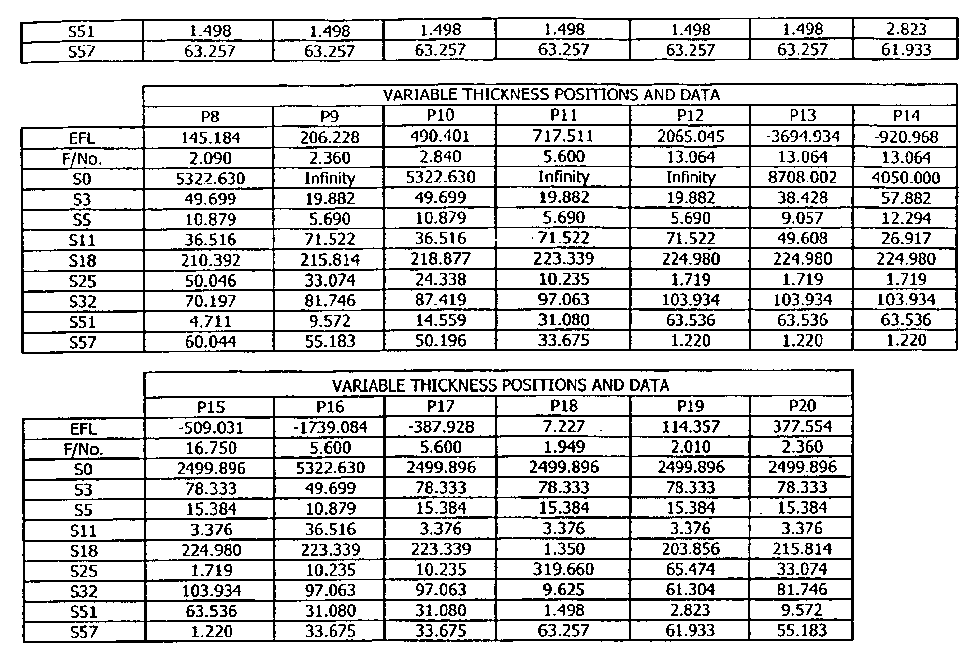
| Surface Groups | Focal Lengths |
| S2-S3 | -349.648 |
| S4-S5 | -581.962 |
| S6-57 | 798.201 |
| S10-S11 | 1258.758 |
| S12-S13 | 672.072 |
| S14-S15 | 709.848 |
| S16-S17 | 646.676 |
| S19-S20 | -64.565 |
| S21-S22 | -526.211 |
| S23-S25 | -554.999 |
| S26-S27 | 135.208 |
| S28-S30 | 113230.702 |
| S31-S32 | 240.348 |
| S34-S35 | -65.863 |
| S36-S37 | 144.623 |
| S38-S40 | 60.255 |
| S41-S43 | -70.987 |
| S44-S45 | 58.010 |
| S46-S47 | 205.873 |
| S48-S49 | 52.593 |
| S50-S51 | 38.634 |
| S52-S53 | -27.000 |
| S54-S55 | -34.933 |
| S56-S57 | -2495.053 |
| S58-S59 | 284.851 |
| S60-S61 | 167.476 |
| S62-S64 | 292.466 |
| S66-S67 | 97.878 |
| S69- 70 | -90.217 |
| S71-S73 | -72.295 |
| S75-S76 | 61.902 |
| S77-S79 | 1261.227 |
| S80-S81 | Infinity |
| S82-S83 | Infinity |
| The coefficients for the surface S12 are: | The coefficients for the surface S26 are: | ||
| K= | 0.01925737 | K= | -0.5574845 |
| A= | -1.3531387e-007 | A= | -1.0833227e-006 |
| B= | -1.5274225e-011 | B= | -9.1904879e-011 |
| C= | -2.0209982e-014 | C= | -1.4775967e-013 |
| D= | 5.4753514e-018 | D= | 6.5701323e-016 |
where: A1, A2, A3, A4 and A5 are coefficients and p is the normalized radial coordinate at the surface.
| The coefficients for the surface S17 are: | The coefficients for the surface S31 are: | ||
| K= | -0.3564029 | K= | 0.4304792 |
| A= | -8.6827410e-007 | A= | 9.5769727e-007 |
| B= | -2.1510889e-010 | B= | 1.3131850e-009 |
| C= | -6.3664850e-014 | C= | -1.4559220e-012 |
| D= | -3.8937870e-018 | D= | 3.1953640e-015 |
where: A1, A2, A3, A4 and A5 are coefficients and p is the normalized radial coordinate at the surface.
| The coefficients for the surface S7 are: | The coefficients for the surface S10 are: | ||
| K= | -0.01834396 | K= | 0.1385814 |
| A= | 4.6192051e-009 | A= | -6.1078514e-008 |
| B= | 2.9277175e-013 | B= | -1.7110958e-012 |
| C= | -5.3760139e-018 | C= | -1.4298682e-015 |
| D= | 4.4429222e-022 | D= | -7.3308393e-019 |
| E= | 0 | E= | 0 |
| The coefficients for the surface 524 are: | The coefficients for the surface S36 are: | ||
| K= | -0.1283323 | K= | U.009973727 |
| A= | -2.7157663e-007 | A= | 3.3999271e-008 |
| B= | 1.4568941e-010 | B= | 1.4717268e-010 |
| C= | -1.4055959e-012 | C= | -1.0665963e-013 |
| D= | 9.7130719e-016 | D= | 6.8463872e-017 |
| E= | 0 | E= | 0 |
| The coefficients for the surface S64 are: | The coefficients for the surface S65 are: | ||
| K= | -4.594951 | K= | -0.2743554 |
| A= | 5.9382510e-006 | A= | 1.2036084e-006 |
| B= | -4.3333569e-009 | B= | 3.8383867e-009 |
| C= | -2.6412286e-013 | C= | -1.5101902e-011 |
| D= | 5.0607811e-015 | D= | 2.3291313e-014 |
| E= | -3.8443669e-018 | E= | -1.3549754e-017 |
where: A1, A2, A3, A4, A5 and A6 are coefficients and p is the normalized radial coordinate at the surface.
| The coefficients for the | The coefficients for the | ||
| K= | -0.3170663 | K= | 0.0000000 |
| A= | 7.1675212e-010 | A= | 8.8834511e-009 |
| B= | 4.6490286e-015 | B= | -1.1017434e-012 |
| C= | 3.1509558e-020 | C= | 4.2407818e-016 |
| D= | -3.0230207e-026 | D= | -4.5843672e-020 |
| E= | 1.8711604e-043 | E= | 0 |
| F= | 7.2023035e-034 | F= | 0 |
| G= | -1.6899714e-038 | G= | 0 |
| The coefficients for the surface S10 are: | The coefficients for the surface S12 are: | ||
| K= | 0.0000000 | K= | 0.1424633 |
| A= | -4.1468720e-008 | A= | -1.3741884e-008 |
| B= | -1.1864804e-012 | B= | 2.0574529e-010 |
| C= | 1.0375271e-016 | C= | 2.2356569e-013 |
| D= | 1.4819552e-020 | D= | -9.2592205e-016 |
| E= | 0 | E= | 0 |
| F= | 0 | F= | 0 |
| G= | 0 | G= | 0 |
| The coefficients for the surface S13 are: | The coefficients for the surface S14 are: | ||
| K= | 0.1341907 | K= | 0.0000000 |
| A= | 2.5853953e-007 | A= | -2.3627230e-006 |
| B= | 6.3040925e-010 | B= | -3.2069853e-009 |
| C= | -8.9182471e-013 | C= | 1.9995538e-012 |
| D= | -2.1087914e-016 | D= | -4.1873811e-015 |
| E= | 0 | E= | -4.5598387e-018 |
| F= | 0 | F= | 1.5355757e-021 |
| G= | 0 | G= | 2.7742963e-025 |
| The coefficients for the surface S15 are: | The coefficients for the surface S16 are: | ||
| K= | 0.0000000 | K= | 0.0000000 |
| A= | -1.9992749e-006 | A= | -5.5264489e-007 |
| B= | -2.7451965e-009 | B= | -3.4855834e-011 |
| C= | 2.5915567e-012 | C= | -1.5605019e-013 |
| D= | -5.4747396e-015 | D= | 8.4346229e-016 |
| E= | 1.0432409e-018 | E= | -2.6930213e-019 |
| F= | -9.7041838e-023 | F= | 7.0886850e-022 |
| G= | 3.5844261e-025 | G= | -4.8763355e-025 |
| The coefficients for the surface S17 are: | The coefficients for the surface S18 are: | ||
| K= | 0.0000000 | K= | 0.0000000 |
| A= | -1.9256081e-007 | A= | 4.5197079e-007 |
| B= | 9.7560057e-012 | B= | -4.7688707e-010 |
| C= | -3.1406997e-013 | C= | -2.2771179e-013 |
| D= | 4.6996712e-016 | D= | -7.381237Se-016 |
| E= | 4.3471337e-019 | E= | 6.1621050e-019 |
| F= | -3.7957715e-022 | F= | -2.9782920e-023 |
| G= | -2.4875152e-026 | G= | -2.8295343e-026 |
| The coefficients for the surface S19 are: | |
| K= | 0.0000000 |
| A= | 3.9066750e-007 |
| B= | -2-6768710e-010 |
| C= | -3.7378469e-013 |
| D= | -4.0450877e-016 |
| E= | 3.9230103e-019 |
| F= | -3.7514135e-023 |
| G= | -8.0738327e-027 |
where: A1, A2, A3, A4 and A5 are coefficients and p is the normalized radial coordinate at the surface.
Claims (25)
- A zoom lens system for forming a final image of an object, said system having an object side and an image side and forming a first intermediate real image between the object and the final image, said system characterized by, in order from the object side to the image side:a first optical unit including at least two lens elements and located between the object and the first intermediate real image, said unit comprising at least one optical subunit which is moved to change the magnification of the first intermediate real image; anda second optical unit including at least two lens elements and located between the first intermediate real image and the final image, at least a portion of which is moved to change the magnification of the final image.
- The zoom lens system as recited in claim 1, the second optical unit comprising at least one optical subunit, and at least one of the optical subunits is movable to hold an axial position of the final image substantially stationary as the focal length of the system is changed.
- The zoom lens system as recited in claim 1, wherein the second optical unit comprises at least one optical subunit and at least one of the optical subunits in each of the first and second optical units moves continuously as the focal length of the system is changed.
- The zoom lens system as recited in claim 1, wherein the second optical unit comprises at least one optical subunit and at least one of the optical subunits in one of the first and second optical units is at least temporarily stationary while at least one of the optical subunits in the other of the first and second optical units moves as the focal length of the system is changed.
- The zoom lens system as recited in claim 1, wherein:(a) the second optical unit comprises at least one optical subunit; and(b) a change in the focal length of the system includes at least one first motion and at least one second motion wherein:(i) the first motion can precede or follow the second motion;(ii) for the first motion, at least one optical subunit of the first optical unit moves without movement of any optical subunit of the second optical unit; and(iii) for the second motion, at least one optical subunit of the second optical unit moves without movement of any optical subunit of the first optical unit.
- The zoom lens system as recited in claim 5, wherein a change in the focal length of the system includes only a single first motion and a single second motion.
- The zoom lens system as recited in claim 1, further comprising a focus unit on the object side of the first optical unit for focusing at least one of the intermediate and final images.
- The zoom lens system as recited in claim 1, wherein the first optical unit comprises an aperture stop and the system further comprises a pupil imaging unit located between the first and second optical units for imaging an exit pupil of the first optical unit to form an entrance pupil of the second optical unit.
- The zoom lens system as recited in claim 1, wherein the second optical unit comprises an aperture stop and the system further comprises a pupil imaging unit located between the first and second optical units for imaging an entrance pupil of the second optical unit to form an exit pupil of the first optical unit.
- The zoom lens system as recited in claim 1, further comprising an image stabilization unit on the image side of the second optical unit for stabilizing the final image.
- The zoom lens system as recited in claim 7, the focus unit comprising two optical subunits that are movable along the optical axis of the zoom lens system.
- The zoom lens system as recited in claim 11, wherein the optical axis is straight.
- The zoom lens system as recited in claim 7, the focus unit comprising seven or fewer lens elements.
- The zoom lens system as recited in claim 10, the image stabilization unit comprising at least one lens element that is laterally movable off the optical axis of the zoom lens system.
- The zoom lens system as recited in claim 10, the image stabilization unit comprising at least one lens element that is axially movable along the optical axis of the zoom lens system.
- The zoom lens system as recited in claim 10, the image stabilization unit comprising at least one laterally movable lens element that is laterally movable off the optical axis of the zoom lens system and at least one axially movable lens element that is axially movable along the optical axis, the at least one laterally movable lens element separated from the at least one axially movable lens element by an air gap, wherein radiation from the object and passing through the air gap is substantially collimated.
- The zoom lens system as recited in claim 14, wherein radiation from the object and passing through the system is substantially collimated at the at least one laterally movable lens element.
- The zoom lens system as recited in claim 15, wherein radiation from the object and passing through the system is substantially collimated at the at least one axially movable lens element.
- The zoom lens system as recited in claim 1, wherein one or more additional intermediate real images are formed between the object and the final image.
- The zoom lens system as recited in claim 19, further comprising one or more additional optical units for changing the size (magnification) of the one or more additional intermediate real images.
- The zoom lens system as recited in claim 1, wherein the first intermediate real image is formed in an air space between optical elements in the zoom lens system and remains in the air space during zooming.
- The zoom lens system as recited in claim 19, wherein the one or more additional intermediate real images are formed in one or more air spaces between optical elements in the zoom lens system and remain in the one or more air spaces during zooming.
- The zoom lens system of claim 1, wherein the system comprises at least one aspheric optical surface.
- The zoom lens system of claim 1, wherein the system comprises at least one diffractive optical surface.
- The zoom lens system of claim 1, wherein the system comprises at least one aspheric optical surface and at least one diffractive optical surface.
Applications Claiming Priority (3)
| Application Number | Priority Date | Filing Date | Title |
|---|---|---|---|
| US39788202P | 2002-07-22 | 2002-07-22 | |
| US397882P | 2002-07-22 | ||
| PCT/US2003/022418 WO2004010199A2 (en) | 2002-07-22 | 2003-07-18 | Zoom lens system |
Publications (2)
| Publication Number | Publication Date |
|---|---|
| EP1523691A2 EP1523691A2 (en) | 2005-04-20 |
| EP1523691B1 true EP1523691B1 (en) | 2006-09-06 |
Family
ID=30771137
Family Applications (1)
| Application Number | Title | Priority Date | Filing Date |
|---|---|---|---|
| EP03765693A Expired - Lifetime EP1523691B1 (en) | 2002-07-22 | 2003-07-18 | Zoom lens system with ultra high zoom ratio |
Country Status (9)
| Country | Link |
|---|---|
| US (2) | US6961188B2 (en) |
| EP (1) | EP1523691B1 (en) |
| JP (1) | JP2006512595A (en) |
| AT (1) | ATE338961T1 (en) |
| AU (1) | AU2003252012B2 (en) |
| CA (1) | CA2490012C (en) |
| DE (1) | DE60308191T2 (en) |
| TW (1) | TWI263797B (en) |
| WO (1) | WO2004010199A2 (en) |
Families Citing this family (52)
| Publication number | Priority date | Publication date | Assignee | Title |
|---|---|---|---|---|
| US7473715B2 (en) * | 2001-05-02 | 2009-01-06 | Zephyros, Inc. | Two component (epoxy/amine) structural foam-in-place material |
| US7150537B2 (en) * | 2002-08-16 | 2006-12-19 | Infocus Corporation | Projection television device and screen |
| JP4379780B2 (en) * | 2003-06-06 | 2009-12-09 | 株式会社ニコン | Zoom lens barrel for microscope and microscope using the same |
| US20060018644A1 (en) * | 2004-07-21 | 2006-01-26 | Stavely Donald J | Apparatus and method for heat sinking a sensor |
| US7710460B2 (en) * | 2004-07-21 | 2010-05-04 | Hewlett-Packard Development Company, L.P. | Method of compensating for an effect of temperature on a control system |
| US7283309B2 (en) * | 2004-08-20 | 2007-10-16 | Panavision International, L.P. | Wide-range, wide-angle, rotatable compound zoom |
| JP5027661B2 (en) * | 2004-08-25 | 2012-09-19 | パナビジョン イメージング リミテッド ライアビリティ カンパニー | Lens control method and apparatus, and camera module incorporating the same |
| US7227682B2 (en) * | 2005-04-08 | 2007-06-05 | Panavision International, L.P. | Wide-range, wide-angle compound zoom with simplified zooming structure |
| DE102006030250A1 (en) * | 2005-06-30 | 2007-01-04 | Pentax Corp. | Optical image stabilizer |
| US9298014B2 (en) * | 2005-07-01 | 2016-03-29 | Flir Systems, Inc. | Image stabilization system |
| US7862188B2 (en) * | 2005-07-01 | 2011-01-04 | Flir Systems, Inc. | Image detection improvement via compensatory high frequency motions of an undedicated mirror |
| JP2007033879A (en) | 2005-07-27 | 2007-02-08 | Sony Corp | Imaging lens device and imaging apparatus |
| US7224535B2 (en) * | 2005-07-29 | 2007-05-29 | Panavision International, L.P. | Zoom lens system |
| TWI314217B (en) * | 2006-09-15 | 2009-09-01 | Asia Optical Co Inc | Periscope-type zooming lens |
| US7768715B2 (en) * | 2007-02-21 | 2010-08-03 | Theia Technologies, Llc | Whole system zoom and varifocal lens with intermediate image |
| JP5115834B2 (en) * | 2007-03-05 | 2013-01-09 | 株式会社ニコン | Zoom lens, optical apparatus, and imaging method |
| US7733581B2 (en) * | 2007-08-24 | 2010-06-08 | Caldwell J Brian | Large aperture imaging optical system |
| US8169717B2 (en) * | 2007-08-24 | 2012-05-01 | Caldwell Photographic, Inc. | Large aperture imaging optical systems |
| JP2011509416A (en) | 2007-12-04 | 2011-03-24 | ブラックアイ オプティクス,エルエルシー | Image stabilization by liquid optics. |
| ES2528124T3 (en) | 2007-12-04 | 2015-02-04 | Blackeye Optics, Llc | Telephoto type zoom lens that has a liquid lens in a fixed group |
| JP5380444B2 (en) * | 2008-06-25 | 2014-01-08 | 株式会社 ニコンビジョン | Relay zoom system |
| US8508864B2 (en) * | 2008-08-25 | 2013-08-13 | Acm Projektentwicklung Gmbh | Objective lens system |
| US7880978B2 (en) * | 2008-08-25 | 2011-02-01 | Acm Projektentwicklung Gmbh | Objective lens system |
| JP5738841B2 (en) | 2009-04-10 | 2015-06-24 | ブラックアイ オプティクス,エルエルシー | Variable optical power system |
| JP5695028B2 (en) | 2009-04-10 | 2015-04-01 | ブラックアイ オプティクス,エルエルシー | Variable optical power system |
| US7961382B2 (en) * | 2009-08-28 | 2011-06-14 | Corning Incorporated | Mid infrared spectral band continuous zoom system |
| JP5312393B2 (en) * | 2010-04-16 | 2013-10-09 | キヤノン株式会社 | Imaging device |
| US8149519B2 (en) * | 2010-07-26 | 2012-04-03 | Panavision International, L.P. | High-speed zoom lens |
| US9025256B2 (en) * | 2011-03-10 | 2015-05-05 | Raytheon Company | Dual field of view refractive optical system for GEO synchronous earth orbit |
| JP5693321B2 (en) | 2011-03-28 | 2015-04-01 | キヤノン株式会社 | Zoom lens and imaging device |
| JP5693322B2 (en) * | 2011-03-28 | 2015-04-01 | キヤノン株式会社 | Zoom lens and imaging device |
| KR101890304B1 (en) | 2011-11-04 | 2018-08-22 | 삼성전자주식회사 | Zoom lens and photographing apparatus |
| US9110276B2 (en) | 2012-01-20 | 2015-08-18 | Raytheon Company | Full-field GEO imager optics with extended spectral coverage |
| US9398232B2 (en) | 2012-03-26 | 2016-07-19 | Nokia Corporation | Special effect video camera |
| JP5871743B2 (en) * | 2012-07-31 | 2016-03-01 | キヤノン株式会社 | Imaging optical system, and projection-type image display device and imaging device using the same |
| US9529181B2 (en) | 2013-10-10 | 2016-12-27 | Nittoh Kogaku K.K. | Zoom lens system and imaging apparatus |
| DE102013112212B4 (en) * | 2013-11-06 | 2022-03-10 | Carl Zeiss Smt Gmbh | Optical zoom device, optical imaging device, optical zoom method and imaging method for microscopy |
| US9479686B2 (en) | 2014-02-19 | 2016-10-25 | Melvyn H Kreitzer | Zoom lens optical system |
| US9910251B2 (en) | 2014-03-19 | 2018-03-06 | Nittoh Inc. | Lens system and imaging apparatus having a lens at each side of an intermediate image which move in synchronization during focusing |
| JPWO2016056147A1 (en) * | 2014-10-08 | 2017-07-20 | オリンパス株式会社 | Imaging optical system, illumination device and observation device |
| US11112592B2 (en) * | 2015-04-24 | 2021-09-07 | Board Of Supervisors Of Louisiana State University And Agricultural And Mechanical College | Fine focus microscope control |
| JP6602186B2 (en) * | 2015-11-30 | 2019-11-06 | キヤノン株式会社 | Converter device and imaging device |
| JP6198862B2 (en) * | 2016-01-14 | 2017-09-20 | キヤノン株式会社 | Imaging optical system, and projection-type image display device and imaging device using the same |
| EP3457191B1 (en) * | 2016-05-09 | 2022-09-14 | Konica Minolta, Inc. | Projection optical system and projector |
| JP6029159B1 (en) * | 2016-05-13 | 2016-11-24 | 株式会社タムロン | Observation optical system, observation imaging apparatus, observation imaging system, imaging lens system, and adjustment method of observation optical system |
| JP6692694B2 (en) * | 2016-05-25 | 2020-05-13 | 富士フイルム株式会社 | Imaging optical system, projection display device, and imaging device |
| JP6712932B2 (en) | 2016-08-30 | 2020-06-24 | 富士フイルム株式会社 | Zoom lens, projection display device, and imaging device |
| CN107450168B (en) * | 2017-09-05 | 2019-03-08 | 嘉兴中润光学科技有限公司 | In dolly-out, dolly-back interchangeable tight shot |
| JP6858153B2 (en) * | 2018-03-28 | 2021-04-14 | 富士フイルム株式会社 | Imaging optics, projection display, and imaging equipment |
| CN110441234B (en) * | 2019-08-08 | 2020-07-10 | 上海御微半导体技术有限公司 | Zoom lens, defect detection device and defect detection method |
| JP6825147B2 (en) * | 2020-04-15 | 2021-02-03 | 富士フイルム株式会社 | Imaging optical system, projection display device, and imaging device |
| CN113820840A (en) | 2020-06-19 | 2021-12-21 | 富士胶片株式会社 | Zoom optical system and imaging device |
Family Cites Families (19)
| Publication number | Priority date | Publication date | Assignee | Title |
|---|---|---|---|---|
| US2454686A (en) * | 1946-07-30 | 1948-11-23 | Frank G Back | Varifocal lens for cameras |
| US3192829A (en) * | 1961-06-16 | 1965-07-06 | Yamaji Keizo | Varifocal lens system of wide varifocal range |
| JPS5441333B2 (en) * | 1973-03-23 | 1979-12-07 | ||
| JPS524461B2 (en) * | 1973-03-23 | 1977-02-04 | ||
| US3947084A (en) * | 1975-02-28 | 1976-03-30 | Hughes Aircraft Company | Long-wave infrared afocal zoom telescope |
| US4411488A (en) * | 1980-05-30 | 1983-10-25 | Barr & Stroud Limited | Afocal zoom refractor telescopes |
| IL69565A0 (en) * | 1982-09-04 | 1983-11-30 | Pilkington Perkin Elmer Ltd | Infra-red lenses |
| US5270857A (en) * | 1987-10-30 | 1993-12-14 | Canon Kabushiki Kaisha | Optical system for stabilizing an image |
| US4909614A (en) * | 1987-11-13 | 1990-03-20 | Canon Kabushiki Kaisha | Variable magnification finder |
| US4971428A (en) * | 1989-03-27 | 1990-11-20 | Lenzar Optics Corporation | Catadioptric zoom lens |
| US5194886A (en) * | 1990-04-03 | 1993-03-16 | Minolta Camera Kabushiki Kaisha | Finder optical system |
| JP3387524B2 (en) * | 1992-07-06 | 2003-03-17 | オリンパス光学工業株式会社 | Variable magnification finder optical system |
| JPH0829738A (en) * | 1994-07-18 | 1996-02-02 | Nikon Corp | Vibration-proof zoom lens |
| US5790309A (en) * | 1994-09-29 | 1998-08-04 | Nikon Corporation | Zoom lens system capable of shifting an image and compensating back focus variation |
| JPH09230234A (en) * | 1996-02-27 | 1997-09-05 | Canon Inc | Zoom lens provided with vibration-proof function |
| US5999310A (en) * | 1996-07-22 | 1999-12-07 | Shafer; David Ross | Ultra-broadband UV microscope imaging system with wide range zoom capability |
| JPH1039210A (en) * | 1996-07-24 | 1998-02-13 | Nikon Corp | Zoom lens |
| JP4004140B2 (en) * | 1998-04-30 | 2007-11-07 | オリンパス株式会社 | Zoom lens using diffractive optical element and image pickup apparatus using the same |
| US6362923B1 (en) * | 2000-03-10 | 2002-03-26 | Kla-Tencor | Lens for microscopic inspection |
-
2003
- 2003-07-18 EP EP03765693A patent/EP1523691B1/en not_active Expired - Lifetime
- 2003-07-18 WO PCT/US2003/022418 patent/WO2004010199A2/en active IP Right Grant
- 2003-07-18 AU AU2003252012A patent/AU2003252012B2/en not_active Expired
- 2003-07-18 DE DE60308191T patent/DE60308191T2/en not_active Expired - Lifetime
- 2003-07-18 CA CA002490012A patent/CA2490012C/en not_active Expired - Lifetime
- 2003-07-18 AT AT03765693T patent/ATE338961T1/en not_active IP Right Cessation
- 2003-07-18 US US10/622,914 patent/US6961188B2/en not_active Expired - Lifetime
- 2003-07-18 JP JP2004523536A patent/JP2006512595A/en active Pending
- 2003-07-22 TW TW092119986A patent/TWI263797B/en not_active IP Right Cessation
-
2005
- 2005-04-29 US US11/119,121 patent/US7012759B2/en not_active Expired - Lifetime
Also Published As
| Publication number | Publication date |
|---|---|
| ATE338961T1 (en) | 2006-09-15 |
| JP2006512595A (en) | 2006-04-13 |
| US20050190434A1 (en) | 2005-09-01 |
| WO2004010199B1 (en) | 2004-05-27 |
| WO2004010199A3 (en) | 2004-03-25 |
| EP1523691A2 (en) | 2005-04-20 |
| DE60308191D1 (en) | 2006-10-19 |
| TWI263797B (en) | 2006-10-11 |
| US6961188B2 (en) | 2005-11-01 |
| CA2490012A1 (en) | 2004-01-29 |
| DE60308191T2 (en) | 2007-08-23 |
| TW200428025A (en) | 2004-12-16 |
| AU2003252012A1 (en) | 2004-02-09 |
| US7012759B2 (en) | 2006-03-14 |
| US20040021953A1 (en) | 2004-02-05 |
| WO2004010199A2 (en) | 2004-01-29 |
| AU2003252012B2 (en) | 2006-08-17 |
| CA2490012C (en) | 2009-11-10 |
Similar Documents
| Publication | Publication Date | Title |
|---|---|---|
| EP1523691B1 (en) | Zoom lens system with ultra high zoom ratio | |
| EP1910881B1 (en) | Zoom lens system | |
| KR101280742B1 (en) | Wide-range, wide-angle compound zoom with simplified zooming structure | |
| US7764438B2 (en) | Zoom lens system and image pickup apparatus using the same | |
| US7283309B2 (en) | Wide-range, wide-angle, rotatable compound zoom | |
| US8228617B2 (en) | Zoom lens and image pickup apparatus having the same | |
| US8405917B2 (en) | Zoom lens, imaging device and information device | |
| US20050259334A1 (en) | Zoom lens system and image pickup apparatus including the same | |
| US7436601B2 (en) | Two-group zoom lens and an electronic imaging apparatus having it | |
| EP2015122A1 (en) | Zoom lens and optical device with the same | |
| JP2004198855A (en) | Zoom lens, camera and personal digital assistance device | |
| JP3897457B2 (en) | Stereoscopic optical system and zoom lens used therefor | |
| JP2006003589A (en) | Variable-focus lens | |
| US20030099042A1 (en) | Zoom lens and camera equipped with zoom lens | |
| JP2004070133A (en) | Zoom lens and camera system | |
| EP1967883B1 (en) | Zoom lens of the telephoto type and having four lens groups | |
| US7085048B2 (en) | Real image type variable magnification finder and imaging apparatus using the same |
Legal Events
| Date | Code | Title | Description |
|---|---|---|---|
| PUAI | Public reference made under article 153(3) epc to a published international application that has entered the european phase |
Free format text: ORIGINAL CODE: 0009012 |
|
| 17P | Request for examination filed |
Effective date: 20050113 |
|
| AK | Designated contracting states |
Kind code of ref document: A2 Designated state(s): AT BE BG CH CY CZ DE DK EE ES FI FR GB GR HU IE IT LI LU MC NL PT RO SE SI SK TR |
|
| AX | Request for extension of the european patent |
Extension state: AL LT LV MK |
|
| DAX | Request for extension of the european patent (deleted) | ||
| GRAP | Despatch of communication of intention to grant a patent |
Free format text: ORIGINAL CODE: EPIDOSNIGR1 |
|
| RTI1 | Title (correction) |
Free format text: ZOOM LENS SYSTEM WITH ULTRA HIGH ZOOM RATIO |
|
| GRAS | Grant fee paid |
Free format text: ORIGINAL CODE: EPIDOSNIGR3 |
|
| GRAA | (expected) grant |
Free format text: ORIGINAL CODE: 0009210 |
|
| AK | Designated contracting states |
Kind code of ref document: B1 Designated state(s): AT BE BG CH CY CZ DE DK EE ES FI FR GB GR HU IE IT LI LU MC NL PT RO SE SI SK TR |
|
| PG25 | Lapsed in a contracting state [announced via postgrant information from national office to epo] |
Ref country code: AT Free format text: LAPSE BECAUSE OF FAILURE TO SUBMIT A TRANSLATION OF THE DESCRIPTION OR TO PAY THE FEE WITHIN THE PRESCRIBED TIME-LIMIT Effective date: 20060906 Ref country code: IT Free format text: LAPSE BECAUSE OF FAILURE TO SUBMIT A TRANSLATION OF THE DESCRIPTION OR TO PAY THE FEE WITHIN THE PRESCRIBED TIME-LIMIT;WARNING: LAPSES OF ITALIAN PATENTS WITH EFFECTIVE DATE BEFORE 2007 MAY HAVE OCCURRED AT ANY TIME BEFORE 2007. THE CORRECT EFFECTIVE DATE MAY BE DIFFERENT FROM THE ONE RECORDED. Effective date: 20060906 Ref country code: FI Free format text: LAPSE BECAUSE OF FAILURE TO SUBMIT A TRANSLATION OF THE DESCRIPTION OR TO PAY THE FEE WITHIN THE PRESCRIBED TIME-LIMIT Effective date: 20060906 Ref country code: SI Free format text: LAPSE BECAUSE OF FAILURE TO SUBMIT A TRANSLATION OF THE DESCRIPTION OR TO PAY THE FEE WITHIN THE PRESCRIBED TIME-LIMIT Effective date: 20060906 Ref country code: RO Free format text: LAPSE BECAUSE OF FAILURE TO SUBMIT A TRANSLATION OF THE DESCRIPTION OR TO PAY THE FEE WITHIN THE PRESCRIBED TIME-LIMIT Effective date: 20060906 Ref country code: CZ Free format text: LAPSE BECAUSE OF FAILURE TO SUBMIT A TRANSLATION OF THE DESCRIPTION OR TO PAY THE FEE WITHIN THE PRESCRIBED TIME-LIMIT Effective date: 20060906 Ref country code: BE Free format text: LAPSE BECAUSE OF FAILURE TO SUBMIT A TRANSLATION OF THE DESCRIPTION OR TO PAY THE FEE WITHIN THE PRESCRIBED TIME-LIMIT Effective date: 20060906 Ref country code: SK Free format text: LAPSE BECAUSE OF FAILURE TO SUBMIT A TRANSLATION OF THE DESCRIPTION OR TO PAY THE FEE WITHIN THE PRESCRIBED TIME-LIMIT Effective date: 20060906 Ref country code: NL Free format text: LAPSE BECAUSE OF FAILURE TO SUBMIT A TRANSLATION OF THE DESCRIPTION OR TO PAY THE FEE WITHIN THE PRESCRIBED TIME-LIMIT Effective date: 20060906 |
|
| REG | Reference to a national code |
Ref country code: GB Ref legal event code: FG4D |
|
| REG | Reference to a national code |
Ref country code: CH Ref legal event code: EP |
|
| REG | Reference to a national code |
Ref country code: IE Ref legal event code: FG4D |
|
| REF | Corresponds to: |
Ref document number: 60308191 Country of ref document: DE Date of ref document: 20061019 Kind code of ref document: P |
|
| PG25 | Lapsed in a contracting state [announced via postgrant information from national office to epo] |
Ref country code: DK Free format text: LAPSE BECAUSE OF FAILURE TO SUBMIT A TRANSLATION OF THE DESCRIPTION OR TO PAY THE FEE WITHIN THE PRESCRIBED TIME-LIMIT Effective date: 20061206 Ref country code: BG Free format text: LAPSE BECAUSE OF FAILURE TO SUBMIT A TRANSLATION OF THE DESCRIPTION OR TO PAY THE FEE WITHIN THE PRESCRIBED TIME-LIMIT Effective date: 20061206 Ref country code: SE Free format text: LAPSE BECAUSE OF FAILURE TO SUBMIT A TRANSLATION OF THE DESCRIPTION OR TO PAY THE FEE WITHIN THE PRESCRIBED TIME-LIMIT Effective date: 20061206 |
|
| PG25 | Lapsed in a contracting state [announced via postgrant information from national office to epo] |
Ref country code: ES Free format text: LAPSE BECAUSE OF FAILURE TO SUBMIT A TRANSLATION OF THE DESCRIPTION OR TO PAY THE FEE WITHIN THE PRESCRIBED TIME-LIMIT Effective date: 20061217 |
|
| REG | Reference to a national code |
Ref country code: CH Ref legal event code: NV Representative=s name: PATENTANWAELTE SCHAAD, BALASS, MENZL & PARTNER AG |
|
| PG25 | Lapsed in a contracting state [announced via postgrant information from national office to epo] |
Ref country code: PT Free format text: LAPSE BECAUSE OF FAILURE TO SUBMIT A TRANSLATION OF THE DESCRIPTION OR TO PAY THE FEE WITHIN THE PRESCRIBED TIME-LIMIT Effective date: 20070219 |
|
| NLV1 | Nl: lapsed or annulled due to failure to fulfill the requirements of art. 29p and 29m of the patents act | ||
| ET | Fr: translation filed | ||
| PLBE | No opposition filed within time limit |
Free format text: ORIGINAL CODE: 0009261 |
|
| STAA | Information on the status of an ep patent application or granted ep patent |
Free format text: STATUS: NO OPPOSITION FILED WITHIN TIME LIMIT |
|
| 26N | No opposition filed |
Effective date: 20070607 |
|
| PG25 | Lapsed in a contracting state [announced via postgrant information from national office to epo] |
Ref country code: MC Free format text: LAPSE BECAUSE OF NON-PAYMENT OF DUE FEES Effective date: 20070731 Ref country code: GR Free format text: LAPSE BECAUSE OF FAILURE TO SUBMIT A TRANSLATION OF THE DESCRIPTION OR TO PAY THE FEE WITHIN THE PRESCRIBED TIME-LIMIT Effective date: 20061207 |
|
| PG25 | Lapsed in a contracting state [announced via postgrant information from national office to epo] |
Ref country code: EE Free format text: LAPSE BECAUSE OF FAILURE TO SUBMIT A TRANSLATION OF THE DESCRIPTION OR TO PAY THE FEE WITHIN THE PRESCRIBED TIME-LIMIT Effective date: 20060906 |
|
| PG25 | Lapsed in a contracting state [announced via postgrant information from national office to epo] |
Ref country code: IE Free format text: LAPSE BECAUSE OF NON-PAYMENT OF DUE FEES Effective date: 20070718 |
|
| PG25 | Lapsed in a contracting state [announced via postgrant information from national office to epo] |
Ref country code: CY Free format text: LAPSE BECAUSE OF FAILURE TO SUBMIT A TRANSLATION OF THE DESCRIPTION OR TO PAY THE FEE WITHIN THE PRESCRIBED TIME-LIMIT Effective date: 20060906 Ref country code: LU Free format text: LAPSE BECAUSE OF NON-PAYMENT OF DUE FEES Effective date: 20070718 |
|
| PG25 | Lapsed in a contracting state [announced via postgrant information from national office to epo] |
Ref country code: HU Free format text: LAPSE BECAUSE OF FAILURE TO SUBMIT A TRANSLATION OF THE DESCRIPTION OR TO PAY THE FEE WITHIN THE PRESCRIBED TIME-LIMIT Effective date: 20070307 Ref country code: TR Free format text: LAPSE BECAUSE OF FAILURE TO SUBMIT A TRANSLATION OF THE DESCRIPTION OR TO PAY THE FEE WITHIN THE PRESCRIBED TIME-LIMIT Effective date: 20060906 |
|
| REG | Reference to a national code |
Ref country code: FR Ref legal event code: PLFP Year of fee payment: 14 |
|
| REG | Reference to a national code |
Ref country code: FR Ref legal event code: PLFP Year of fee payment: 15 |
|
| REG | Reference to a national code |
Ref country code: FR Ref legal event code: PLFP Year of fee payment: 16 |
|
| PGFP | Annual fee paid to national office [announced via postgrant information from national office to epo] |
Ref country code: GB Payment date: 20220623 Year of fee payment: 20 |
|
| PGFP | Annual fee paid to national office [announced via postgrant information from national office to epo] |
Ref country code: DE Payment date: 20220624 Year of fee payment: 20 |
|
| PGFP | Annual fee paid to national office [announced via postgrant information from national office to epo] |
Ref country code: FR Payment date: 20220709 Year of fee payment: 20 |
|
| PGFP | Annual fee paid to national office [announced via postgrant information from national office to epo] |
Ref country code: CH Payment date: 20220701 Year of fee payment: 20 |
|
| REG | Reference to a national code |
Ref country code: DE Ref legal event code: R071 Ref document number: 60308191 Country of ref document: DE |
|
| REG | Reference to a national code |
Ref country code: CH Ref legal event code: PL |
|
| REG | Reference to a national code |
Ref country code: GB Ref legal event code: PE20 Expiry date: 20230717 |
|
| PG25 | Lapsed in a contracting state [announced via postgrant information from national office to epo] |
Ref country code: GB Free format text: LAPSE BECAUSE OF EXPIRATION OF PROTECTION Effective date: 20230717 |