EP1271218B1 - Tunable liquid microlens - Google Patents
Tunable liquid microlens Download PDFInfo
- Publication number
- EP1271218B1 EP1271218B1 EP02252096A EP02252096A EP1271218B1 EP 1271218 B1 EP1271218 B1 EP 1271218B1 EP 02252096 A EP02252096 A EP 02252096A EP 02252096 A EP02252096 A EP 02252096A EP 1271218 B1 EP1271218 B1 EP 1271218B1
- Authority
- EP
- European Patent Office
- Prior art keywords
- droplet
- electrodes
- microlens
- insulating layer
- liquid
- Prior art date
- Legal status (The legal status is an assumption and is not a legal conclusion. Google has not performed a legal analysis and makes no representation as to the accuracy of the status listed.)
- Expired - Lifetime
Links
Images


Classifications
-
- G—PHYSICS
- G02—OPTICS
- G02B—OPTICAL ELEMENTS, SYSTEMS OR APPARATUS
- G02B26/00—Optical devices or arrangements for the control of light using movable or deformable optical elements
- G02B26/004—Optical devices or arrangements for the control of light using movable or deformable optical elements based on a displacement or a deformation of a fluid
- G02B26/005—Optical devices or arrangements for the control of light using movable or deformable optical elements based on a displacement or a deformation of a fluid based on electrowetting
-
- G—PHYSICS
- G02—OPTICS
- G02B—OPTICAL ELEMENTS, SYSTEMS OR APPARATUS
- G02B3/00—Simple or compound lenses
- G02B3/12—Fluid-filled or evacuated lenses
- G02B3/14—Fluid-filled or evacuated lenses of variable focal length
-
- G—PHYSICS
- G02—OPTICS
- G02B—OPTICAL ELEMENTS, SYSTEMS OR APPARATUS
- G02B6/00—Light guides; Structural details of arrangements comprising light guides and other optical elements, e.g. couplings
- G02B6/24—Coupling light guides
- G02B6/42—Coupling light guides with opto-electronic elements
- G02B6/4201—Packages, e.g. shape, construction, internal or external details
- G02B6/4204—Packages, e.g. shape, construction, internal or external details the coupling comprising intermediate optical elements, e.g. lenses, holograms
- G02B6/4206—Optical features
-
- G—PHYSICS
- G02—OPTICS
- G02B—OPTICAL ELEMENTS, SYSTEMS OR APPARATUS
- G02B6/00—Light guides; Structural details of arrangements comprising light guides and other optical elements, e.g. couplings
- G02B6/24—Coupling light guides
- G02B6/42—Coupling light guides with opto-electronic elements
- G02B6/4201—Packages, e.g. shape, construction, internal or external details
- G02B6/4204—Packages, e.g. shape, construction, internal or external details the coupling comprising intermediate optical elements, e.g. lenses, holograms
- G02B6/4214—Packages, e.g. shape, construction, internal or external details the coupling comprising intermediate optical elements, e.g. lenses, holograms the intermediate optical element having redirecting reflective means, e.g. mirrors, prisms for deflecting the radiation from horizontal to down- or upward direction toward a device
Definitions
- the present invention relates to microlenses, and more particularly to liquid microlenses.
- tunable microlenses are either gradient index (GRIN) lenses with the refraction index controlled electrostatically or flexible polymeric lenses with the shape controlled mechanically. Both technologies have inherent limitations that impose severe restrictions on the performance of these existing tunable microlenses.
- GRIN gradient index
- Tunable gradient index lenses have inherent limitations associated with the relatively small electro-optic coefficients found in the majority of electro-optic materials. This results in a small optical path modulation and, therefore, requires thick lenses or very high voltages to be employed. In addition, many electro-optic materials show strong birefringence that causes polarization dependence of the microlens properties.
- Mechanically adjustable flexible lenses typically have a substantially wider range of tunability than the gradient index lenses. However, they require external actuation devices, such as micropumps, to operate. Microintegration of such devices involves substantial problems, especially severe in the case where a two-dimensional array of tunable microlenses is required.
- microlenses utilizing self assembled monolayers, however, also suffer from several problems, including severe limitations on material selection and strong hysteresis leading to the failure of the microlens to return to an original shape after a tuning voltage is disconnected. Additionally, none of the above-described microlenses allow for both lens position adjustment and focal length tuning.
- FR-A-2769375 discloses a variable focus lens having a droplet of an insulating liquid disposed on an insulating wall of a chamber.
- a conductive liquid fills the chamber and surrounds the droplet.
- the lens include means for centering the edge of the droplet when a voltage is applied between the conducting liquid and electrodes disposed below the insulating layer.
- US-A-5486337 discloses a method and apparatus for manipulating small droplets of liquid for analysis, detection or research. Droplets are placed on wettable positioning electrodes on a non-wettable substrate. Voltages are applied to the positioning electrodes to charge the droplets, and voltages of the opposite polarity are applied to target electrodes, thereby attracting the droplets from the positioning electrodes towards the target electrodes.
- US-A-4,569575 provides a device for moving fluid globules to circulate within a capillary space by means of pairs of electrodes that establish capture sites.
- the electrodes of two successive pairs have in common at least one indentation comprising a convex part and a concave part.
- the device may be used in visual displays and electrical data storage.
- a tunable liquid Microlens, apparatus and method according to the invention are as set out in the independent claims. Preferred forms are set out in the dependent claims.
- a tunable liquid microlens includes an insulating layer, a droplet of a transparent conducting liquid disposed on a first surface of the insulating layer and a plurality of electrodes insulated from the droplet by the insulating layer.
- the plurality of electrodes are disposed such that they may be selectively biased to create a respective voltage potential between the droplet and each of the plurality of electrodes, whereby a contact angle between the droplet and the first surface is variable and the droplet may be repositioned along the first surface.
- transparent it is meant transparent at the light frequency of interest, which may or may not be visible.
- the tunable liquid microlens allows for both lens position adjustment and focal length tuning. In addition, the tunable liquid microlens provides greater freedom in material selection.
- the microlens 10 includes a small droplet 12 of a transparent liquid, such as water, typically (but not necessarily) with a diameter from several micrometers to several millimeters.
- the droplet 12 is disposed on a transparent substrate 14.
- the substrate is typically hydrophobic or includes a hydrophobic coating.
- the liquid and substrate need only be transparent to light waves having a wavelength within a selected range. Light waves are illustrated by reference numeral 16. Light waves pass through liquid microlens 10 and focus at a focal point or focal spot (designated by reference numeral 18) in a focal plane that is a focal distance "f" from the contact plane between droplet 12 and substrate 14.
- the contact angle " ⁇ " between the droplet 12 and the substrate 14 is determined by interfacial tensions " ⁇ ", generally measured in milli-Newtons per meter (mN/m).
- ⁇ S-V is the interfacial tension between the substrate and the air, gas or other liquid that surrounds the substrate 14
- ⁇ L-V is the interfacial tension between the droplet 12 and the air, gas or other liquid that surrounds the droplet 12
- ⁇ S-L is the interfacial tension between the substrate 14 and the droplet 12.
- the focal length in meters is a function of the radius R and the refractive indices "n", where n Liquid is the refractive index of the droplet 12 and n Vapor is the refractive index of the air, gas or other liquid that surrounds the droplet 12.
- Equation (3) f R n Liquid -n Vapor
- the refractive index of the substrate is not important because of the parallel entry and exit planes for the light waves.
- FIG.1B demonstrates that the phenomena of electrowetting may be used to reversibly change the contact angle ⁇ between a droplet 22 of a conducting liquid (which may or may not be transparent) and a dielectric insulating layer 24 having a thickness designated as "d" and a dielectric constant ⁇ r .
- An electrode, such as metal electrode 26, is positioned below the dielectric layer 24 and is insulated from the droplet 22 by layer 24.
- the droplet 22 may be, for example, a water droplet, and the substrate 24 may be, for example, a Teflon/Parylene surface.
- the droplet 22 When no voltage difference is present between the droplet 22 and the electrode 26, the droplet 22 maintains a shape defined by the volume of the droplet 22 and contact angle ⁇ 1 , where ⁇ 1 is determined by the interfacial tensions ⁇ as explained above.
- the dashed line 28 illustrates that the the droplet 22 spreads equally across layer 24 from its central position relative to electrode 26 when a voltage is applied between electrode 26 and droplet 22.
- the voltage may range from several volts to several hundred volts.
- the contact angle ⁇ decreases from ⁇ 1 to ⁇ 2 when the voltage is applied, regardless of polarity, between electrode 26 and the droplet 22.
- the amount of spreading i.e., as determined by the difference between ⁇ 1 and ⁇ 2 , is a function of the applied voltage V.
- ⁇ L-V is the droplet interfacial tension described above
- ⁇ r is the dielectric constant of the insulating layer
- ⁇ 0 is 8.85 x 10 -12 F/m - the permittivity of a vacuum.
- FIGS. 2A and 2B illustrate a tunable liquid microlens that is capable of varying both position and focal length as described hereafter.
- a tunable liquid microlens 100 includes a droplet 102 of a transparent, conductive liquid disposed on a first surface of a transparent, dielectric insulating layer 104.
- the insulating layer 104 may be, for example, a polyimide coated with a fluorinated polymer, such as a highly fluorinated hydrocarbon.
- the insulating layer 104 should provide predetermined values of contact angle and contact angle hysteresis and have a high dielectric breakdown strength that is appropriate for the applied voltages.
- the microlens 100 includes a plurality of electrodes 106a-106d insulated from the droplet 102 by insulating layer 104.
- the microlens 100 may also include a transparent supporting substrate 110 which supports the electrodes 106 and insulating layer 104.
- the electrodes 106 and the supporting substrate 110 may be, for example, gold and glass, respectively.
- FIG. 2B is a top plan view of an exemplary configuration for the electrodes 106a-106d. Although one configuration of four electrodes 106a-106d is shown, other numbers, combinations and patterns of electrodes 106 may be utilized depending upon the desired level of control over the tuning of the microlens 100. Each electrode 106a-106d is coupled to a respective voltage V 1 -V 4 and droplet 102, which is centered initially relative to the electrodes 106, is coupled to a droplet electrode 108, which is coupled to a voltage Vo.
- FIG. 2C illustrates this initial position of droplet 102 with a dashed line.
- the position of droplet 102 and the focal length of the microlens 100 can be adjusted by selectively applying a voltage potential between the droplet 102 and the electrodes 106.
- the droplet 102 spreads equally within quadrants I, II, III, and IV (i.e., equally along lateral axes X and Y) as shown by the dashed line of FIG. 2D.
- the contact angle ⁇ between the droplet 102 and insulating layer 104 decreases.
- the electrodes 106 can be selectively biased relative to the droplet electrode (and thus droplet 102) in any number of combinations in order to adjust the contact angle ⁇ and thereby to modify the focal length of the microlens 100.
- the electrodes 106 can be selectively biased in any number of combinations to reposition the droplet 102 relative to an initial location on the insulating layer 104, whereby the lateral position of the focal spot of the microlens is adjusted.
- the microlens allows for the adjustment of the focal spot in three dimensions - the position of the focal spot as determined by the focal length and the lateral position of the focal spot in the focal plane that is parallel with the first surface of the microlens and is a focal length away from the microlens.
- FIG. 3A illustrates one manner of coupling the droplet 102 to a voltage Vo, such as ground or other constant voltage level.
- Microlens 100a may include a supporting substrate 110a which includes a conductive glass, such as indium tin oxide glass. The conductive glass is coupled to voltage Vo and an electrode 116 couples the substrate 110a to the droplet 102. The electrode 116 and supporting substrate 110a may collectively be considered a droplet electrode.
- FIG. 3A also illustrates that the insulating dielectric layer 104 may include a dielectric layer 114 and a hydrophobic coating layer 112. The coating layer 112 should provide a relatively high contact angle ⁇ .
- insulating layer 104a includes a coating layer 112 that is a Teflon film disposed on a polyimide dielectric layer 114.
- droplet electrode 116 may be, for example, a gold electrode evaporated or otherwise deposited on a first surface of an insulating layer 104 (not shown) in an area or plurality of areas that ensures that the electrode 116 maintains contact with the droplet 102 when the droplet 102 changes position along the first surface of the insulating layer 104.
- the electrode 116 is disposed to maintain contact with the droplet 102 when the droplet 102 changes position, the droplet 102 is substantially disposed on the first surface of insulating layer 104.
- the microlens 100B may include a supporting substrate 110a that need not be conductive and may be, for example, non-conductive glass that serves as a mechanical support layer for insulating layer 104 and the electrodes 106. In that case, droplet electrode 116 may be coupled directly to a voltage Vo. Alternatively, the supporting layer 110a may be a conductive glass substrate that is coupled to a voltage Vo. In that embodiment, the droplet electrode 116 may be coupled to the supporting layer 110a. Also shown in FIG. 3B are electrodes 106a-106d and their respective power leads 118a-118d which are coupled to voltages V 1 -V 4 , respectively. Although an insulating layer 104 is not shown in FIG. 3B, this is for illustrative purposes only, and an insulating layer 104 insulates the droplet 102 and electrode 116 from electrodes 106a-106d.
- FIG. 3C illustrates an exemplary embodiment of a tunable liquid microlens 100C where no electrode 116 is required, thereby reducing any potential interference with the microlens from electrode 116.
- Microlens 100C includes droplet 102 disposed on a first surface of an insulating layer 104b.
- Microlens 100C also includes a transparent conductive supporting layer 110a which serves as a droplet electrode disposed along a second surface of insulating layer 104b opposite the first surface of insulating layer 104b.
- Microlens 100C is shown in cross-section to illustrate that insulating layer 104b includes an aperture 118 defined by the insulating layer 104b and continuing there through.
- the droplet 102 occupies at least a part of the aperture 118, thereby placing the droplet 102 in electrical communication with the droplet electrode, i.e., supporting substrate 110a.
- the supporting substrate 110a is then coupled to a voltage Vo.
- the insulating layer 104b also does not have to be transparent as long as the aperture is wide enough so that the light that penetrates through the aperture is sufficient for the particular application.
- the liquid droplet may be any liquid which is transparent to the desired wavelength and which is intrinsically conductive or which can be made conductive, such as through the use of various additive. Typical examples includes aqueous solutions of various salts.
- the electrodes may be any solid conductive materials, which may or may not be transparent, such as gold, aluminum, or indium tin oxide glass.
- the insulating layer may be any solid dielectric or a set of solid dielectrics that provide high enough dielectric strength and predefined values of contact angle and contact angle hysteresis. The insulating layer may or may not be transparent. Examples include solid polymers, such as polyimide and parylene.
- the supporting substrate may be any substrate that is transparent to a given wavelength, such as glass or a solid polymer.
- the applied voltages depend upon the selected materials, the layout of the microlens, and the desired change in the contact angle, as guided by the above equations (1)-(4). Typical voltages may vary between 0 volts and approximately 200 volts, although the acceptable voltages are not limited to this range.
- the liquid droplet of the microlens may be substantially encompassed by a liquid that is immiscible with the droplet.
- the surrounding liquid may help to prevent the microlens droplet from evaporating.
- various oils or high molecular weight alcohols e.g., pentanol, octanol, etc. may be used.
- the microlens 100C of FIG. 3C was tested.
- the microlens included a droplet 102 including 20 ⁇ l of 0.01 aqueous KNO 3 solution.
- the insulating layer 104b included a 3 ⁇ m thick polyimide layer coated with a very thin ( ⁇ 0.02 ⁇ m) layer of a highly fluorinated polymer that provided an initial contact angle of approximately 109°.
- a set of four gold electrodes 106 were arranged as shown in FIGS. 2B and 3C.
- the microlens included an ITO (indium tin oxide) glass plate as a conductive transparent supporting substrate 110a shown in FIG. 3C. Operating voltages between 0V and approximately 150V were applied.
- the described microlens may be designed to have a desired contact angle ⁇ when there is no voltage difference between the droplet and the electrodes 106 and a desired contact angle hysteresis. This may be achieved by selecting appropriate materials, dimensions, and volumes as guided by the equations set forth above.
- the microlens therefore allows substantial freedom in both droplet curvature and position control, thereby leading to a wide range of tunability in the microlens, focal length, focal spot position, and numerical aperture.
- the microlens of the present invention may be utilized in several optoelectronic applications.
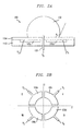
- the microlens may be used to achieve optimal coupling between an optical signal transmitter 204, such as a laser, and an optical signal receiver 202, such as a photodetector. This is illustrated in FIG. 4. It should be understood from FIG. 4 that the optical signal from transmitter 204 is diverging and will be focused behind the focal plane 206.
- the lens focal distance and lateral positioning of the focal spot 208 within focal plane 206 of the microlens 100 may be adjusted as described above by selectively biasing the plurality of electrodes 106 to achieve this optimal coupling.
- the biasing electrodes can be selectively biased until the highest power is detected at receiver 202 - representing the optimal coupling between transmitter 204 and receiver 202.
- optoelectronic packages i.e., physical apparatuses incorporating optoelectronic components such as lasers and/ or photodetectors, are calibrated by physically moving component parts to achieve optimal coupling. This process can be slow and quite expensive.
- the need to physically align component parts to achieve optimal coupling is eliminated. Rather, the focal length and lateral position of the focal spot of the microlens of the present invention may be adjusted to redirect an optical signal from a transmitter to a fixed receiver.
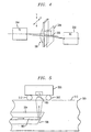
- a microlens 100 is utilized to couple an optoelectronic component, such as a photodetector 506 that is surface mounted through a ball grid array 512 on a printed circuit board 500, with an embedded planar waveguide 504.
- an optoelectronic component such as a photodetector 506 that is surface mounted through a ball grid array 512 on a printed circuit board 500
- Light propagates through a core 502 of planar waveguide 504 as indicated by the directional arrows. The light is reflected by a mirror edge 508 towards a top surface 510 of the printed circuit board 500.
- a tunable liquid microlens 100 is disposed on the top surface 510 of the printed circuit board 500 and directs the light 502 toward photodetector 506 in the direction shown.
- the electrodes of the tunable liquid microlens 100 may be selectively biased to adjust the focal length and lateral focal spot position of the microlens 100 in order to tune the microlens 100 to optimize the transmission of the light from the planar waveguide 504 to the photodetector 506.
- the shape of the microlens is maintained by the application of the appropriate voltage.
Applications Claiming Priority (2)
| Application Number | Priority Date | Filing Date | Title |
|---|---|---|---|
| US884605 | 2001-06-19 | ||
| US09/884,605 US6538823B2 (en) | 2001-06-19 | 2001-06-19 | Tunable liquid microlens |
Publications (2)
| Publication Number | Publication Date |
|---|---|
| EP1271218A1 EP1271218A1 (en) | 2003-01-02 |
| EP1271218B1 true EP1271218B1 (en) | 2005-02-02 |
Family
ID=25384984
Family Applications (1)
| Application Number | Title | Priority Date | Filing Date |
|---|---|---|---|
| EP02252096A Expired - Lifetime EP1271218B1 (en) | 2001-06-19 | 2002-03-22 | Tunable liquid microlens |
Country Status (5)
| Country | Link |
|---|---|
| US (1) | US6538823B2 (un) |
| EP (1) | EP1271218B1 (un) |
| JP (1) | JP4351420B2 (un) |
| CA (1) | CA2381745C (un) |
| DE (1) | DE60202815T2 (un) |
Families Citing this family (111)
| Publication number | Priority date | Publication date | Assignee | Title |
|---|---|---|---|---|
| FR2791439B1 (fr) * | 1999-03-26 | 2002-01-25 | Univ Joseph Fourier | Dispositif de centrage d'une goutte |
| US20050002113A1 (en) * | 1997-10-08 | 2005-01-06 | Varioptic | Drop centering device |
| US6965480B2 (en) * | 2001-06-19 | 2005-11-15 | Lucent Technologies Inc. | Method and apparatus for calibrating a tunable microlens |
| US6665127B2 (en) * | 2002-04-30 | 2003-12-16 | Lucent Technologies Inc. | Method and apparatus for aligning a photo-tunable microlens |
| US7110646B2 (en) * | 2002-03-08 | 2006-09-19 | Lucent Technologies Inc. | Tunable microfluidic optical fiber devices and systems |
| US6936196B2 (en) * | 2002-03-12 | 2005-08-30 | Lucent Technologies Inc. | Solidifiable tunable liquid microlens |
| US6829415B2 (en) * | 2002-08-30 | 2004-12-07 | Lucent Technologies Inc. | Optical waveguide devices with electro-wetting actuation |
| US6911132B2 (en) * | 2002-09-24 | 2005-06-28 | Duke University | Apparatus for manipulating droplets by electrowetting-based techniques |
| US7329545B2 (en) * | 2002-09-24 | 2008-02-12 | Duke University | Methods for sampling a liquid flow |
| US20040151828A1 (en) * | 2003-02-04 | 2004-08-05 | Anis Zribi | Method for fabrication and alignment of micro and nanoscale optics using surface tension gradients |
| FR2851052B1 (fr) * | 2003-02-12 | 2005-05-27 | Commissariat Energie Atomique | Lentille a focale variable comprenant un substrat en silicium, en arseniure de gallium ou en quartz |
| US6891682B2 (en) * | 2003-03-03 | 2005-05-10 | Lucent Technologies Inc. | Lenses with tunable liquid optical elements |
| JP4220543B2 (ja) | 2003-03-17 | 2009-02-04 | ノキア コーポレイション | 画像の横方向調整のための方法および装置 |
| US6952313B2 (en) | 2003-03-17 | 2005-10-04 | Nokia Corporation | Method and device for image zooming |
| US6778328B1 (en) * | 2003-03-28 | 2004-08-17 | Lucent Technologies Inc. | Tunable field of view liquid microlens |
| US20040191127A1 (en) * | 2003-03-31 | 2004-09-30 | Avinoam Kornblit | Method and apparatus for controlling the movement of a liquid on a nanostructured or microstructured surface |
| US7106519B2 (en) * | 2003-07-31 | 2006-09-12 | Lucent Technologies Inc. | Tunable micro-lens arrays |
| US6847493B1 (en) | 2003-08-08 | 2005-01-25 | Lucent Technologies Inc. | Optical beamsplitter with electro-wetting actuation |
| US8072688B2 (en) * | 2003-09-24 | 2011-12-06 | Alcatel Lucent | Method for calibrating a photo-tunable microlens |
| JP4319188B2 (ja) * | 2003-10-08 | 2009-08-26 | 株式会社蔵王ニコン | 基板搬送装置及び基板搬送方法、露光装置及び露光方法、デバイス製造装置及びデバイス製造方法 |
| CN100478075C (zh) * | 2003-11-17 | 2009-04-15 | 皇家飞利浦电子股份有限公司 | 用于操纵流体实体的系统 |
| JP4237610B2 (ja) * | 2003-12-19 | 2009-03-11 | 株式会社東芝 | 保守支援方法及びプログラム |
| KR101377815B1 (ko) * | 2004-02-03 | 2014-03-26 | 가부시키가이샤 니콘 | 노광 장치 및 디바이스 제조 방법 |
| DE102004011660A1 (de) * | 2004-03-10 | 2005-10-06 | Daimlerchrysler Ag | Linsenvorrichtung, Scheinwerfer und Beleuchtungseinrichtung |
| JP4595369B2 (ja) * | 2004-03-31 | 2010-12-08 | ブラザー工業株式会社 | 液体移送ヘッド及びこれを備えた液体移送装置 |
| US6977777B1 (en) | 2004-06-18 | 2005-12-20 | Sandia Corporation | Active optical zoom system |
| KR100636433B1 (ko) | 2004-08-18 | 2006-10-18 | 엘지전자 주식회사 | 렌즈 소자 |
| US7927783B2 (en) * | 2004-08-18 | 2011-04-19 | Alcatel-Lucent Usa Inc. | Tunable lithography with a refractive mask |
| ATE485888T1 (de) | 2004-08-26 | 2010-11-15 | Life Technologies Corp | Elektrobenetzende abgabevorrichtungen und dazugehörige verfahren |
| US7780830B2 (en) * | 2004-10-18 | 2010-08-24 | Hewlett-Packard Development Company, L.P. | Electro-wetting on dielectric for pin-style fluid delivery |
| WO2006064949A1 (ja) | 2004-12-17 | 2006-06-22 | Brother Kogyo Kabushiki Kaisha | キャピラリーエレクトロウェッティング現象を用いたバルブ及びアクチュエータ |
| EP1830219A1 (en) * | 2004-12-21 | 2007-09-05 | Zeon Corporation | Optical device |
| EP1859330B1 (en) | 2005-01-28 | 2012-07-04 | Duke University | Apparatuses and methods for manipulating droplets on a printed circuit board |
| WO2006095303A1 (en) * | 2005-03-11 | 2006-09-14 | Koninklijke Philips Electronics N.V. | Optical scanning device |
| JP2006302367A (ja) * | 2005-04-19 | 2006-11-02 | Ricoh Co Ltd | 光ピックアップ、調整方法及び光情報処理装置 |
| EP1739461B1 (de) * | 2005-06-29 | 2010-10-20 | WaveLight GmbH | Vorrichtung und Verfahren zum Untersuchen der Akkommodationsfähigkeit eines Auges |
| US7666665B2 (en) | 2005-08-31 | 2010-02-23 | Alcatel-Lucent Usa Inc. | Low adsorption surface |
| WO2007033326A2 (en) * | 2005-09-14 | 2007-03-22 | Welch Allyn, Inc. | Medical apparatus comprising and adaptive lens |
| US8721161B2 (en) | 2005-09-15 | 2014-05-13 | Alcatel Lucent | Fluid oscillations on structured surfaces |
| US7412938B2 (en) * | 2005-09-15 | 2008-08-19 | Lucent Technologies Inc. | Structured surfaces with controlled flow resistance |
| US20070059213A1 (en) * | 2005-09-15 | 2007-03-15 | Lucent Technologies Inc. | Heat-induced transitions on a structured surface |
| US8734003B2 (en) * | 2005-09-15 | 2014-05-27 | Alcatel Lucent | Micro-chemical mixing |
| US8287808B2 (en) * | 2005-09-15 | 2012-10-16 | Alcatel Lucent | Surface for reversible wetting-dewetting |
| US8027095B2 (en) * | 2005-10-11 | 2011-09-27 | Hand Held Products, Inc. | Control systems for adaptive lens |
| US7474470B2 (en) * | 2005-12-14 | 2009-01-06 | Honeywell International Inc. | Devices and methods for redirecting light |
| US20070147816A1 (en) * | 2005-12-27 | 2007-06-28 | Tessera, Inc. | Camera modules with liquid optical elements |
| US7443597B2 (en) * | 2005-12-27 | 2008-10-28 | Tessera, Inc. | Liquid lens with piezoelectric voltage converter |
| US7382544B2 (en) * | 2006-02-10 | 2008-06-03 | Honeywell International Inc. | Devices and related methods for light distribution |
| US7358833B2 (en) * | 2006-03-14 | 2008-04-15 | Lucent Technologies Inc. | Method and apparatus for signal processing using electrowetting |
| US8637317B2 (en) * | 2006-04-18 | 2014-01-28 | Advanced Liquid Logic, Inc. | Method of washing beads |
| US9476856B2 (en) | 2006-04-13 | 2016-10-25 | Advanced Liquid Logic, Inc. | Droplet-based affinity assays |
| US8492168B2 (en) * | 2006-04-18 | 2013-07-23 | Advanced Liquid Logic Inc. | Droplet-based affinity assays |
| US20140193807A1 (en) | 2006-04-18 | 2014-07-10 | Advanced Liquid Logic, Inc. | Bead manipulation techniques |
| US8613889B2 (en) * | 2006-04-13 | 2013-12-24 | Advanced Liquid Logic, Inc. | Droplet-based washing |
| US8658111B2 (en) | 2006-04-18 | 2014-02-25 | Advanced Liquid Logic, Inc. | Droplet actuators, modified fluids and methods |
| US8980198B2 (en) | 2006-04-18 | 2015-03-17 | Advanced Liquid Logic, Inc. | Filler fluids for droplet operations |
| US8809068B2 (en) | 2006-04-18 | 2014-08-19 | Advanced Liquid Logic, Inc. | Manipulation of beads in droplets and methods for manipulating droplets |
| US8716015B2 (en) | 2006-04-18 | 2014-05-06 | Advanced Liquid Logic, Inc. | Manipulation of cells on a droplet actuator |
| US10078078B2 (en) | 2006-04-18 | 2018-09-18 | Advanced Liquid Logic, Inc. | Bead incubation and washing on a droplet actuator |
| US8470606B2 (en) * | 2006-04-18 | 2013-06-25 | Duke University | Manipulation of beads in droplets and methods for splitting droplets |
| US7901947B2 (en) * | 2006-04-18 | 2011-03-08 | Advanced Liquid Logic, Inc. | Droplet-based particle sorting |
| US8637324B2 (en) | 2006-04-18 | 2014-01-28 | Advanced Liquid Logic, Inc. | Bead incubation and washing on a droplet actuator |
| US7439014B2 (en) | 2006-04-18 | 2008-10-21 | Advanced Liquid Logic, Inc. | Droplet-based surface modification and washing |
| US8389297B2 (en) * | 2006-04-18 | 2013-03-05 | Duke University | Droplet-based affinity assay device and system |
| WO2007123908A2 (en) | 2006-04-18 | 2007-11-01 | Advanced Liquid Logic, Inc. | Droplet-based multiwell operations |
| US7816121B2 (en) * | 2006-04-18 | 2010-10-19 | Advanced Liquid Logic, Inc. | Droplet actuation system and method |
| US7815871B2 (en) * | 2006-04-18 | 2010-10-19 | Advanced Liquid Logic, Inc. | Droplet microactuator system |
| US7763471B2 (en) * | 2006-04-18 | 2010-07-27 | Advanced Liquid Logic, Inc. | Method of electrowetting droplet operations for protein crystallization |
| US8041463B2 (en) * | 2006-05-09 | 2011-10-18 | Advanced Liquid Logic, Inc. | Modular droplet actuator drive |
| US7822510B2 (en) * | 2006-05-09 | 2010-10-26 | Advanced Liquid Logic, Inc. | Systems, methods, and products for graphically illustrating and controlling a droplet actuator |
| US7939021B2 (en) * | 2007-05-09 | 2011-05-10 | Advanced Liquid Logic, Inc. | Droplet actuator analyzer with cartridge |
| DE102006035925B3 (de) * | 2006-07-31 | 2008-02-21 | Albert-Ludwigs-Universität Freiburg | Vorrichtung und Verfahren zur elektrischen Bewegung von Flüssigkeitstropfen |
| DE602007006494D1 (de) | 2006-08-01 | 2010-06-24 | Panasonic Corp | Kameraeinrichtung, flüssigkeitslinse und bilderfassungsverfahren |
| US7525722B2 (en) * | 2006-08-31 | 2009-04-28 | Alcatel-Lucent Usa Inc. | Liquid mirror |
| TWI442086B (zh) | 2006-08-31 | 2014-06-21 | Liquavista Bv | 包含一單元陣列之電子裝置及其操作方法 |
| US20080063022A1 (en) * | 2006-09-12 | 2008-03-13 | Kevin Thomas Gahagan | Semiconductor laser and tunable fluid lenses |
| US7697187B2 (en) * | 2006-09-29 | 2010-04-13 | Sony Corporation | Electrowetting device and varifocal lens, optical pickup device, optical recording/reproduction device, droplet operation device, optical element, zoom lens, imaging device, light modulating device, and display device using the same |
| US7324287B1 (en) | 2006-11-07 | 2008-01-29 | Corning Incorporated | Multi-fluid lenses and optical devices incorporating the same |
| US20080117521A1 (en) * | 2006-11-17 | 2008-05-22 | Lucent Technologies Inc. | Liquid lenses with cycloalkanes |
| US20080123956A1 (en) * | 2006-11-28 | 2008-05-29 | Honeywell International Inc. | Active environment scanning method and device |
| US7586681B2 (en) * | 2006-11-29 | 2009-09-08 | Honeywell International Inc. | Directional display |
| JP5040493B2 (ja) * | 2006-12-04 | 2012-10-03 | ソニー株式会社 | 撮像装置及び撮像方法 |
| US7813047B2 (en) * | 2006-12-15 | 2010-10-12 | Hand Held Products, Inc. | Apparatus and method comprising deformable lens element |
| US8027096B2 (en) | 2006-12-15 | 2011-09-27 | Hand Held Products, Inc. | Focus module and components with actuator polymer control |
| KR100826452B1 (ko) * | 2006-12-18 | 2008-04-29 | 삼성전기주식회사 | 광학 부품 및 그 제조방법 |
| US7791815B2 (en) * | 2007-03-13 | 2010-09-07 | Varioptic S.A. | Dielectric coatings for electrowetting applications |
| TWI369506B (en) * | 2007-04-25 | 2012-08-01 | Nat Univ Tsing Hua | Optical axis orientating device for liquid lens |
| US8268246B2 (en) | 2007-08-09 | 2012-09-18 | Advanced Liquid Logic Inc | PCB droplet actuator fabrication |
| KR101505699B1 (ko) * | 2007-10-08 | 2015-03-24 | 블랙아이 옵틱스, 엘엘씨 | 액체 옵틱스 줌 렌즈 시스템 및 이미징 장치 |
| US7862183B2 (en) * | 2007-10-16 | 2011-01-04 | Alcatel-Lucent Usa Inc. | Speckle reduction using a tunable liquid lens |
| ES2528124T3 (es) | 2007-12-04 | 2015-02-04 | Blackeye Optics, Llc | Lente de zoom de tipo telefoto que tiene una lente líquida en un grupo fijo |
| WO2009073388A2 (en) | 2007-12-04 | 2009-06-11 | Blackeye Optics, Llc | Image stabilization system using one, or more, liquid lens |
| US20090186304A1 (en) * | 2008-01-22 | 2009-07-23 | Micron Technology, Inc. | Gravity and pressure enhanced reflow process to form lens structures |
| US20090195882A1 (en) * | 2008-02-05 | 2009-08-06 | Bolle Cristian A | Mechanical lenses |
| WO2010015093A1 (en) | 2008-08-08 | 2010-02-11 | Optotune Ag | Electroactive optical device |
| CN102272653B (zh) | 2008-12-30 | 2015-06-17 | 得利捷扫描集团有限公司 | 液体透镜图像捕捉装置 |
| JP5695028B2 (ja) | 2009-04-10 | 2015-04-01 | ブラックアイ オプティクス,エルエルシー | 可変屈折力光学系 |
| JP5738841B2 (ja) * | 2009-04-10 | 2015-06-24 | ブラックアイ オプティクス,エルエルシー | 可変屈折力光学系 |
| EP2239600A1 (en) | 2010-06-02 | 2010-10-13 | Optotune AG | Adjustable optical lens |
| US8944647B2 (en) | 2010-09-02 | 2015-02-03 | Optotune Ag | Illumination source with variable divergence |
| EP2633341B1 (en) | 2010-10-26 | 2019-12-25 | Optotune AG | Variable focus lens having two liquid chambers |
| US20120138121A1 (en) * | 2010-12-07 | 2012-06-07 | Afshin Izadian | Adaptive controllable lenses for solar energy collection |
| DE102011016852A1 (de) * | 2011-04-06 | 2012-10-11 | Laser- Und Medizin-Technologie Gmbh, Berlin | Seitlich gerichtet abstrahlende sowie konfokal detektierende Faseroptiken |
| WO2013009927A2 (en) | 2011-07-11 | 2013-01-17 | Advanced Liquid Logic, Inc. | Droplet actuators and techniques for droplet-based assays |
| KR20130072502A (ko) * | 2011-12-22 | 2013-07-02 | 삼성디스플레이 주식회사 | 시차 배리어 패널 및 이를 포함하는 표시 장치 |
| JP6200642B2 (ja) * | 2012-11-30 | 2017-09-20 | 日本オクラロ株式会社 | 光学装置 |
| EP2837957B1 (de) | 2013-08-13 | 2016-11-23 | Telesto GmbH | Flüssigkeitslinse zur kontrollierten Einstellung einer bestimmten Brennweite |
| US9572487B2 (en) | 2014-02-03 | 2017-02-21 | Parrot Drones | Methods and devices for interactive adjustment of a parameter of a continuously variable optical lens |
| JP2017227760A (ja) | 2016-06-22 | 2017-12-28 | ソニー株式会社 | 液体レンズおよびその駆動方法、撮像装置、並びに表示装置 |
| CN111007065B (zh) * | 2019-12-24 | 2022-10-14 | 暨南大学 | 液滴微透镜混合溶液、液滴微透镜阵列制备方法、形变方法、成像方法、信号增强方法 |
| KR102608098B1 (ko) * | 2021-03-31 | 2023-11-30 | 재단법인 오송첨단의료산업진흥재단 | 초점 가변형 액체렌즈 및 이의 제조방법 |
Family Cites Families (19)
| Publication number | Priority date | Publication date | Assignee | Title |
|---|---|---|---|---|
| GB1239141A (un) | 1969-03-07 | 1971-07-14 | ||
| US4030813A (en) * | 1974-12-20 | 1977-06-21 | Matsushita Electric Industrial Co., Ltd. | Control element having liquid layer attainable to geometrically uneven state in response to electrical signal |
| US4118270A (en) | 1976-02-18 | 1978-10-03 | Harris Corporation | Micro lens formation at optical fiber ends |
| US4137060A (en) | 1977-07-18 | 1979-01-30 | Robert Bosch Gmbh | Method of forming a lens at the end of a light guide |
| US4653847A (en) | 1981-02-23 | 1987-03-31 | Motorola, Inc. | Fiber optics semiconductor package |
| US4338352A (en) | 1981-02-23 | 1982-07-06 | Mcdonnell Douglas Corporation | Process for producing guided wave lens on optical fibers |
| FR2502345B1 (un) | 1981-03-17 | 1985-01-04 | Thomson Csf | |
| NL8204961A (nl) | 1982-12-23 | 1984-07-16 | Philips Nv | Monomode optische transmissievezel met een taps eindgedeelte en werkwijze voor het vervaardigen daarvan. |
| FR2548431B1 (fr) | 1983-06-30 | 1985-10-25 | Thomson Csf | Dispositif a commande electrique de deplacement de fluide |
| CA1243105A (en) | 1984-07-09 | 1988-10-11 | Giok D. Khoe | Electro-optical device comprising a laser diode, an input transmission fibre and an output transmission fibre |
| GB8421105D0 (en) | 1984-08-20 | 1984-09-26 | British Telecomm | Microlens |
| US4948214A (en) | 1989-07-10 | 1990-08-14 | Eastman Kodak Company | Step-index light guide and gradient index microlens device for LED imaging |
| US5518863A (en) | 1992-01-31 | 1996-05-21 | Institut National D'optique | Method of changing the optical invariant of multifiber fiber-optic elements |
| DE4310291A1 (de) | 1993-03-30 | 1994-10-06 | Sel Alcatel Ag | Optischer Koppler |
| US5486337A (en) | 1994-02-18 | 1996-01-23 | General Atomics | Device for electrostatic manipulation of droplets |
| US6014259A (en) | 1995-06-07 | 2000-01-11 | Wohlstadter; Jacob N. | Three dimensional imaging system |
| US5659330A (en) | 1996-05-31 | 1997-08-19 | Xerox Corporation | Electrocapillary color display sheet |
| DE19623270C2 (de) | 1996-06-11 | 1998-05-20 | Juergen Rebel | Adaptives optisches Abbildungssystem zur Abbildung eines von einem Laser emittierten Strahlenbündels |
| FR2769375B1 (fr) | 1997-10-08 | 2001-01-19 | Univ Joseph Fourier | Lentille a focale variable |
-
2001
- 2001-06-19 US US09/884,605 patent/US6538823B2/en not_active Expired - Lifetime
-
2002
- 2002-03-22 EP EP02252096A patent/EP1271218B1/en not_active Expired - Lifetime
- 2002-03-22 DE DE60202815T patent/DE60202815T2/de not_active Expired - Lifetime
- 2002-04-15 CA CA002381745A patent/CA2381745C/en not_active Expired - Fee Related
- 2002-05-23 JP JP2002149586A patent/JP4351420B2/ja not_active Expired - Lifetime
Non-Patent Citations (1)
| Title |
|---|
| EUROSENSORS XV, CONFERENCE PROCEEDINGS, vol. 2, 10 June 2001 (2001-06-10), BERLIN, GERMANY, pages 1348 - 1351 * |
Also Published As
| Publication number | Publication date |
|---|---|
| CA2381745C (en) | 2006-12-05 |
| CA2381745A1 (en) | 2002-12-19 |
| JP2003050303A (ja) | 2003-02-21 |
| DE60202815T2 (de) | 2006-01-19 |
| DE60202815D1 (de) | 2005-03-10 |
| US6538823B2 (en) | 2003-03-25 |
| US20020196558A1 (en) | 2002-12-26 |
| EP1271218A1 (en) | 2003-01-02 |
| JP4351420B2 (ja) | 2009-10-28 |
Similar Documents
| Publication | Publication Date | Title |
|---|---|---|
| EP1271218B1 (en) | Tunable liquid microlens | |
| EP1293807B1 (en) | Tunable liquid microlens with lubrication assisted electrowetting | |
| US7006299B2 (en) | Method and apparatus for calibrating a tunable microlens | |
| US6665127B2 (en) | Method and apparatus for aligning a photo-tunable microlens | |
| US6778328B1 (en) | Tunable field of view liquid microlens | |
| EP1304591A1 (en) | Photo-tunable liquid microlens | |
| US6936196B2 (en) | Solidifiable tunable liquid microlens | |
| US20080117521A1 (en) | Liquid lenses with cycloalkanes | |
| US20220003842A1 (en) | Lidar Module With Monolithic Array | |
| CN100363760C (zh) | 具有电润湿驱动的分光镜 | |
| US11340399B2 (en) | In-plane MEMS optical switch | |
| US11360270B2 (en) | MEMS optical switch with stop control | |
| WO2007007242A2 (en) | Device for controlling the shape and direction of light | |
| US11307483B2 (en) | MEMS optical switch with dual cantilever couplers | |
| US8072688B2 (en) | Method for calibrating a photo-tunable microlens | |
| US11300852B2 (en) | MEMS optical switch with a cantilever coupler | |
| CN116068826A (zh) | 液晶超表面、液晶超表面的制作方法和激光雷达 | |
| CN115986419A (zh) | 波束调控结构及方法、扫描设备 |
Legal Events
| Date | Code | Title | Description |
|---|---|---|---|
| PUAI | Public reference made under article 153(3) epc to a published international application that has entered the european phase |
Free format text: ORIGINAL CODE: 0009012 |
|
| 17P | Request for examination filed |
Effective date: 20020412 |
|
| AK | Designated contracting states |
Kind code of ref document: A1 Designated state(s): AT BE CH CY DE DK ES FI FR GB GR IE IT LI LU MC NL PT SE TR |
|
| AX | Request for extension of the european patent |
Free format text: AL;LT;LV;MK;RO;SI |
|
| 17Q | First examination report despatched |
Effective date: 20030212 |
|
| AKX | Designation fees paid |
Designated state(s): DE FR |
|
| GRAP | Despatch of communication of intention to grant a patent |
Free format text: ORIGINAL CODE: EPIDOSNIGR1 |
|
| GRAS | Grant fee paid |
Free format text: ORIGINAL CODE: EPIDOSNIGR3 |
|
| GRAA | (expected) grant |
Free format text: ORIGINAL CODE: 0009210 |
|
| AK | Designated contracting states |
Kind code of ref document: B1 Designated state(s): DE FR |
|
| REF | Corresponds to: |
Ref document number: 60202815 Country of ref document: DE Date of ref document: 20050310 Kind code of ref document: P |
|
| PLBE | No opposition filed within time limit |
Free format text: ORIGINAL CODE: 0009261 |
|
| STAA | Information on the status of an ep patent application or granted ep patent |
Free format text: STATUS: NO OPPOSITION FILED WITHIN TIME LIMIT |
|
| ET | Fr: translation filed | ||
| 26N | No opposition filed |
Effective date: 20051103 |
|
| REG | Reference to a national code |
Ref country code: FR Ref legal event code: CD Owner name: ALCATEL-LUCENT USA INC. Effective date: 20131122 |
|
| REG | Reference to a national code |
Ref country code: FR Ref legal event code: GC Effective date: 20140410 |
|
| REG | Reference to a national code |
Ref country code: FR Ref legal event code: RG Effective date: 20141015 |
|
| REG | Reference to a national code |
Ref country code: FR Ref legal event code: PLFP Year of fee payment: 14 |
|
| REG | Reference to a national code |
Ref country code: FR Ref legal event code: PLFP Year of fee payment: 15 |
|
| REG | Reference to a national code |
Ref country code: FR Ref legal event code: PLFP Year of fee payment: 16 |
|
| REG | Reference to a national code |
Ref country code: FR Ref legal event code: PLFP Year of fee payment: 17 |
|
| PGFP | Annual fee paid to national office [announced via postgrant information from national office to epo] |
Ref country code: DE Payment date: 20190312 Year of fee payment: 18 |
|
| PGFP | Annual fee paid to national office [announced via postgrant information from national office to epo] |
Ref country code: FR Payment date: 20190213 Year of fee payment: 18 |
|
| REG | Reference to a national code |
Ref country code: DE Ref legal event code: R119 Ref document number: 60202815 Country of ref document: DE |
|
| PG25 | Lapsed in a contracting state [announced via postgrant information from national office to epo] |
Ref country code: FR Free format text: LAPSE BECAUSE OF NON-PAYMENT OF DUE FEES Effective date: 20200331 Ref country code: DE Free format text: LAPSE BECAUSE OF NON-PAYMENT OF DUE FEES Effective date: 20201001 |