EP1176487A1 - Autonomously navigating robot system - Google Patents
Autonomously navigating robot system Download PDFInfo
- Publication number
- EP1176487A1 EP1176487A1 EP00116088A EP00116088A EP1176487A1 EP 1176487 A1 EP1176487 A1 EP 1176487A1 EP 00116088 A EP00116088 A EP 00116088A EP 00116088 A EP00116088 A EP 00116088A EP 1176487 A1 EP1176487 A1 EP 1176487A1
- Authority
- EP
- European Patent Office
- Prior art keywords
- chassis
- robot system
- autonomously navigating
- navigating robot
- bar
- Prior art date
- Legal status (The legal status is an assumption and is not a legal conclusion. Google has not performed a legal analysis and makes no representation as to the accuracy of the status listed.)
- Withdrawn
Links
Images


Classifications
-
- G—PHYSICS
- G05—CONTROLLING; REGULATING
- G05D—SYSTEMS FOR CONTROLLING OR REGULATING NON-ELECTRIC VARIABLES
- G05D1/00—Control of position, course or altitude of land, water, air, or space vehicles, e.g. automatic pilot
- G05D1/02—Control of position or course in two dimensions
- G05D1/021—Control of position or course in two dimensions specially adapted to land vehicles
- G05D1/0231—Control of position or course in two dimensions specially adapted to land vehicles using optical position detecting means
- G05D1/0246—Control of position or course in two dimensions specially adapted to land vehicles using optical position detecting means using a video camera in combination with image processing means
- G05D1/0248—Control of position or course in two dimensions specially adapted to land vehicles using optical position detecting means using a video camera in combination with image processing means in combination with a laser
Definitions
- the invention relates to an autonomously navigating robot system and in particular a robot system that the relative orientation of the robot in environment in an efficient way.
- Geometrically classified objects provide an orientation aid to get into these To be able to move environments.
- This guidance is provided, for example through landmarks, i.e. natural or artificial landmarks, the robot system by means of a suitable detection device recognizes.
- the detection devices known to date require calibration and usually also require measuring the distance of the robot to the landmark.
- Use alternative known robot systems Pattern orientation (of landmarks) for orientation in your environment in camera images or orient themselves due to a three-dimensional Reconstruction of the environment. All of these procedures are both in view on the required hardware as well as on the software quite expensive.
- the invention is based on the task of an autonomously navigating To create robot system, its orientation in its environment simplified way.
- Line or bar patterns are projected into the environment, which consists of at least two bars running at an angle not equal to 0 ° to each other or lines.
- a bar pattern from electromagnetic Radiation in particular laser radiation and preferably visible light is generated by the generating device, which is preferably a Projector acts, emitted into the environment. That of objects in the Projection pattern is reflected by a detection device, which is, in particular, a camera. The captured image of the reflected projection pattern is then in evaluated by an evaluation unit.
- the orientation or alignment takes place According to the invention based on the current recorded by the camera Line or bar reflection pattern and taking into account of previous studies of the course and arrangement of reflected line or bar patterns that were previously used for the line or bar pattern projection in different, known orientations of the robot in the area. According to the invention So the orientation is based on the examination of the course (Distortion) of the individual bars or lines of the reflection pattern.
- the orientation of the Robot not determined based on a pattern recognition. Rather, the The course of the individual bars or lines of the reflected pattern was examined. This examination is carried out in particular on the basis of the determination of maximum and minimum values, i.e. similar to a mathematical function course analysis. In other words, the distortion or in particular the curvature and the direction of curvature of the individual Bars or lines are examined to determine the shape of the objects the environment, which must also be known, the orientation of the robot in the area.
- the projection pattern is expediently a Cross of two lines crossing at right angles in their centers.
- the autonomously navigating robot system according to the invention in a pipe system consisting of essentially round cross sections, used in particular essentially circular tubes cross, branch, are curved and / or different from at least one extend inspection shaft directed transversely to their courses, so can be based on the curvature of the projected against the inner wall of the pipes and are detected by these reflected bar or line patterns, at what angle the current direction of travel to the longitudinal axis of the Pipe piece runs in which the robot is currently located.
- inventive System it is therefore possible to always follow the pipe system to traverse the longitudinal axes of his pipe sections with the robot.
- the advantage of the robot system according to the invention can be seen in that the orientation technique according to the invention has no distance measurements and no camera calibration or any calibration of the reflected Pattern detecting device needed.
- the Orientation technology provided according to the invention is based on the pure one Determination of the current direction of travel of the robot system within the Surroundings. So this orientation technique is in a regular structure Environments can be used very efficiently and reliably.
- FIG. 1 shows a chassis 10 of a robot 12 in general.
- the chassis 10 is provided with a drive device indicated at 14, via which, for example, the wheels 16 of the chassis 10 are driven.
- a device for generating is located on the chassis 10 electromagnetic radiation in the form of a laser projector 18 and a Device for detecting a pattern reflected from the environment electromagnetic radiation in the form of a camera 20.
- the camera 20 is into the environment at a different angle from the laser projector 18 directed and takes that projected by the laser projector 18 into the environment and projection light patterns reflected from surrounding objects on.
- the laser projector 18 projects a line pattern 22 consisting of two there are intersecting lines 24, 26 at right angles. From these two lines runs the line 24, based on the chassis 10 at right angles to the Axes of the wheels 16, while the line 26 is parallel to these axes.
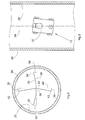
- FIGS. 4 and 6 Examples of the one on the inner wall 28 essentially in cross section round tube 30 reflected line pattern 32 can be found in FIGS. 4 and 6.
- the corresponding orientation of the robot 12 relative to the Longitudinal axis 34 is shown in FIGS. 3 and 5 reproduced
Abstract
Description
Die Erfindung betrifft ein autonom navigierendes Robotersystem und insbesondere ein Robotersystem, das die relative Orientierung des Roboters in seiner Umgebung auf effiziente Weise ermöglicht.The invention relates to an autonomously navigating robot system and in particular a robot system that the relative orientation of the robot in environment in an efficient way.
Autonom navigierende Robotersysteme benötigen in einer Umgebung mit geometrisch klassifizierten Objekten eine Orientierungshilfe, um sich in diesen Umgebungen bewegen zu können. Diese Orientierungshilfe erfolgt beispielsweise durch Landmarken, d.h. natürliche oder künstliche Orientierungspunkten, die das Robotersystem mittels einer geeigneten Detektionsvorrichtung erkennt. Die bisher bekannten Detektionsvorrichtungen bedürfen der Kalibrierung und erfordern zumeist auch die Messung der Distanz des Roboters zur Landmarke. Alternative bekannte Robotersysteme nutzen zur Orientierung in ihrer Umgebung die Mustererkennung (der Landmarken) in Kamerabildern bzw. orientieren sich aufgrund einer dreidimensionalen Rekonstruktion der Umgebung. All diese Verfahren sind sowohl im Hinblick auf die benötigte Hardware als auch auf die Software recht aufwendig.Autonomously navigating robot systems need in one environment Geometrically classified objects provide an orientation aid to get into these To be able to move environments. This guidance is provided, for example through landmarks, i.e. natural or artificial landmarks, the robot system by means of a suitable detection device recognizes. The detection devices known to date require calibration and usually also require measuring the distance of the robot to the landmark. Use alternative known robot systems Pattern orientation (of landmarks) for orientation in your environment in camera images or orient themselves due to a three-dimensional Reconstruction of the environment. All of these procedures are both in view on the required hardware as well as on the software quite expensive.
Der Erfindung liegt die Aufgabe zu Grunde, ein autonom navigierendes Robotersystem zu schaffen, dessen Orientierung in seiner Umgebung auf vereinfachte Art und Weise erfolgt.The invention is based on the task of an autonomously navigating To create robot system, its orientation in its environment simplified way.
Zur Lösung dieser Aufgabe wird mit der Erfindung ein autonom navigierendes Robotersystem vorgeschlagen, das versehen ist mit
- einem Fahrgestell, das eine Antriebsvorrichtung zum Manövrieren des Fahrgestells in einer Umgebung aufweist,
- einer auf dem Fahrgestell angeordneten Vorrichtung zur Erzeugung elektromagnetischer Strahlung und zur gerichteten Aussendung dieser Strahlung in die Umgebung,
- wobei die elektromagnetische Strahlung in Form mindestens zweier Balken ausgesendet wird, die unter einem Winkel ungleich null Grad zueinander verlaufen,
- einer auf dem Fahrgestell angeordneten Vorrichtung zur Erfassung des aus der Umgebung reflektierten Musters der elektromagnetischen Strahlung,
- wobei die Erfassungsvorrichtung versetzt zur Erzeugungs- und Aussendevorrichtung angeordnet ist, und
- einer Auswerteeinheit zur Auswertung des Verlaufs und der Anordnung der Balken des von der Erfassungsvorrichtung erfassten Balkenmusters,
- wobei die Auswerteeinheit unter Berücksichtigung von vorherigen Untersuchungen des Verlaufs und der Anordnung von bei Aussendung elektromagnetischer Strahlung in Form der mindestens zwei winklig zueinander verlaufenden Balken in unterschiedlichen bekannten Richtungen in die Umgebung aus dieser reflektierten Balkenmustern die dem augenblicklich erfassten Balkenmuster entsprechende Ist-Ausrichtung des Fahrgestells in der Umgebung ermittelt und die Antriebsvorrichtung des Fahrgestells zur Erzielung einer gewünschten Soll-Ausrichtung ansteuert.
- a chassis which has a drive device for maneuvering the chassis in an environment,
- a device arranged on the chassis for generating electromagnetic radiation and for the directed emission of this radiation into the environment,
- wherein the electromagnetic radiation is emitted in the form of at least two bars which run at an angle other than zero degrees to one another,
- a device arranged on the chassis for detecting the pattern of the electromagnetic radiation reflected from the surroundings,
- wherein the detection device is arranged offset from the generating and sending device, and
- an evaluation unit for evaluating the course and the arrangement of the bars of the bar pattern detected by the detection device,
- the evaluation unit, taking into account previous examinations of the course and the arrangement of electromagnetic radiation in the form of the at least two bars running at an angle to one another in different known directions into the surroundings from these reflected bar patterns, the actual alignment of the chassis corresponding to the bar pattern currently detected in determined the environment and controls the drive device of the chassis to achieve a desired target orientation.
Zur Orientierung wird bei dem erfindungsgemäßem Robotersystem ein Linien- oder Balkenmuster in die Umgebung projiziert, das aus mindestens zwei unter einem Winkel von ungleich 0° zueinander verlaufenden Balken oder Linien besteht. Ein derartiges Balkenmuster aus elektromagnetischer Strahlung, insbesondere Laserstrahlung und vorzugsweise sichtbarem Licht wird von der Erzeugungsvorrichtung, bei der es sich vorzugsweise um einen Projektor handelt, in die Umgebung ausgesendet. Das von Objekten in der Umgebung reflektierte Projektionsmuster wird von einer Erfassungsvorrichtung, bei der es sich insbesondere um eine Kamera handelt, aufgenommen. Das erfasste Bild des reflektierten Projektionsmusters wird anschließend in einer Auswerteeinheit ausgewertet. Die Orientierung bzw. Ausrichtung erfolgt erfindungsgemäß anhand des von der Kamera aufgenommenen aktuellen Linien- bzw. Balkenreflektionsmusters und unter Berücksichtigung von vorherigen Untersuchungen des Verlaufs und der Anordnung von reflektierten Linien- oder Balkenmustern, die zuvor bei der Linien- bzw. Balkenmusterprojektion in unterschiedlichen, jeweils bekannten Orientierungen des Roboters in der Umgebung gewonnen worden sind. Erfindungsgemäß erfolgt also die Orientierung anhand der Untersuchung des Verlaufs (Verzerrung) der einzelnen Balken bzw. Linien des Reflektionsmusters.For orientation purposes, in the robot system according to the invention Line or bar patterns are projected into the environment, which consists of at least two bars running at an angle not equal to 0 ° to each other or lines. Such a bar pattern from electromagnetic Radiation, in particular laser radiation and preferably visible light is generated by the generating device, which is preferably a Projector acts, emitted into the environment. That of objects in the Projection pattern is reflected by a detection device, which is, in particular, a camera. The captured image of the reflected projection pattern is then in evaluated by an evaluation unit. The orientation or alignment takes place According to the invention based on the current recorded by the camera Line or bar reflection pattern and taking into account of previous studies of the course and arrangement of reflected line or bar patterns that were previously used for the line or bar pattern projection in different, known orientations of the robot in the area. According to the invention So the orientation is based on the examination of the course (Distortion) of the individual bars or lines of the reflection pattern.
Bei dem erfindungsgemäßem Robotersystem wird die Orientierung des Roboters nicht anhand einer Mustererkennung ermittelt. Vielmehr wird der Verlauf der einzelnen Balken bzw. Linien des reflektierten Musters untersucht. Diese Untersuchung erfolgt insbesondere anhand der Bestimmung von Maximal- und Minimalwerten, also ähnlich einer mathematischen Funktionsverlaufsuntersuchung. Mit anderen Worten wird also die Verzerrung oder insbesondere die Krümmung und die Richtung der Krümmung der einzelnen Balken bzw. Linien untersucht, um daraus anhand der Form der Objekte der Umgebung, die ebenfalls bekannt sein müssen, die Ausrichtung des Roboters in der Umgebung zu ermitteln.In the robot system according to the invention, the orientation of the Robot not determined based on a pattern recognition. Rather, the The course of the individual bars or lines of the reflected pattern was examined. This examination is carried out in particular on the basis of the determination of maximum and minimum values, i.e. similar to a mathematical function course analysis. In other words, the distortion or in particular the curvature and the direction of curvature of the individual Bars or lines are examined to determine the shape of the objects the environment, which must also be known, the orientation of the robot in the area.
Bei dem Projektionsmuster handelt es sich zweckmäßigerweise um ein Kreuz aus zwei sich rechtwinklig in ihren Mittelpunkten kreuzenden Linien.The projection pattern is expediently a Cross of two lines crossing at right angles in their centers.
Wird das erfindungsgemäße autonom navigierende Robotersystem beispielsweise in einem Rohrsystem aus im Querschnitt im wesentlichen runden, insbesondere im wesentlichen kreisrunden Rohren eingesetzt, die sich kreuzen, verzweigen, gekrümmt sind und/oder sich von mindestens einem quer zu ihren Verläufen gerichteten Inspektionsschacht aus erstrecken, so kann anhand der Krümmung der gegen die Innenwand der Rohre projizierten und von diesen reflektierten Balken- oder Linienmusters detektiert werden, unter welchem Winkel die aktuelle Fahrtrichtung zur Längsachse des Rohrstücks läuft, in dem sich der Roboter gerade befindet. Mit dem erfindungsgemäßem System ist es also möglich, das Rohrsystem stets entlang der Längsachsen seiner Rohrstücke mit dem Roboter zu durchfahren.For example, the autonomously navigating robot system according to the invention in a pipe system consisting of essentially round cross sections, used in particular essentially circular tubes cross, branch, are curved and / or different from at least one extend inspection shaft directed transversely to their courses, so can be based on the curvature of the projected against the inner wall of the pipes and are detected by these reflected bar or line patterns, at what angle the current direction of travel to the longitudinal axis of the Pipe piece runs in which the robot is currently located. With the inventive System it is therefore possible to always follow the pipe system to traverse the longitudinal axes of his pipe sections with the robot.
Der Vorteil des erfindungsgemäßem Robotersystems ist darin zu sehen, dass die erfindungsgemäße Orientierungstechnik keine Distanzmessungen und keine Kamerakalibrierung bzw. keinerlei Kalibrierung des das reflektierte Muster erfassenden Erfassungsvorrichtung benötigt. Die erfindungsgemäß vorgesehene Orientierungstechnik basiert auf der reinen Feststellung der aktuellen Fahrtrichtung des Robotersystems innerhalb der Umgebung. Damit ist diese Orientierungstechnik in regulär strukturierten Umgebungen sehr effizient und zuverlässig einsetzbar.The advantage of the robot system according to the invention can be seen in that the orientation technique according to the invention has no distance measurements and no camera calibration or any calibration of the reflected Pattern detecting device needed. The Orientation technology provided according to the invention is based on the pure one Determination of the current direction of travel of the robot system within the Surroundings. So this orientation technique is in a regular structure Environments can be used very efficiently and reliably.
Die Erfindung wird nachfolgend anhand der Zeichnungen näher erläutert.The invention is explained in more detail below with reference to the drawings.
Im einzelnen zeigen:
- Fig. 1
- schematisch und in Seitendarstellung ein Ausführungsbeispiel für ein autonom navigierendes Fahrgestell eines Robotersystems zur Inspektion von Abwasserkanalsystemen,
- Fig. 2
- eine Vorderansicht des in Seitenansicht dargestellten Fahrgestells gemäß Fig. 1 und
- Fign. 3 bis 6
- Beispiele für mögliche Ausrichtungen des Fahrgestells und für die sich bei diesen Ausrichtungen jeweils ergebenden gegen die Rohrinnenwand projizierten und von dieser reflektierten Linienmusters.
- Fig. 1
- schematically and in side view an embodiment for an autonomously navigating chassis of a robot system for inspecting sewer systems,
- Fig. 2
- a front view of the chassis shown in side view of FIG. 1 and
- FIGS. 3 to 6
- Examples of possible orientations of the chassis and of the line patterns which result in each of these orientations and which are projected against and reflected by the inner tube wall.
Fig. 1 zeigt ganz allgemein ein Fahrgestell 10 eines Roboters 12. Das Fahrgestell
10 ist mit einer bei 14 angedeuteten Antriebsvorrichtung versehen,
über die beispielsweise die Räder 16 des Fahrgestells 10 angetrieben werden.
Auf dem Fahrgestell 10 befindet sich eine Vorrichtung zur Erzeugung
elektromagnetischer Strahlung in Form eines Laserprojektors 18 sowie eine
Vorrichtung zur Erfassung eines aus der Umgebung reflektierten Musters
elektromagnetischer Strahlung in Form einer Kamera 20. Die Kamera 20 ist
unter einem vom Laserprojektor 18 verschiedenen Winkel in die Umgebung
gerichtet und nimmt das von dem Laserprojektor 18 in die Umgebung projizierte
und von Objekten der Umgebung reflektierte Projektionslichtmuster
auf. Wie anhand der Vorderansicht des Roboters 12 gemäß Fig. 2 zu erkennen
ist, projiziert der Laserprojektor 18 ein Linienmuster 22, das aus zwei
sich rechtwinklig kreuzenden Linien 24,26 besteht. Von diesen beiden Linien
verläuft die Linie 24, bezogen auf das Fahrgestell 10 rechtwinklig zur den
Achsen der Räder 16, während die Linie 26 parallel zur diesen Achsen verläuft.1 shows a
Beispiele für die an der Innenwand 28 eines im Querschnitt im wesentlichen
runden Rohres 30 reflektierten Linienmuster 32 finden sich in den Fign. 4
und 6. Die dazu korrespondierende Ausrichtung des Roboters 12 relativ zur
Längsachse 34 ist in den Fign. 3 und 5 wiedergegebenExamples of the one on the
Betrachtet man beispielsweise Fig. 4, so wird erkennbar, wie man durch
Untersuchung und Analyse des reflektierten Linienmusters 32 in einer Auswerteeinheit
36 des Roboters 12 dessen gegenwärtige Orientierung ermitteln
kann. Zu diesem Zweck werden die Abweichungen 36 und 38 der Endpunkte
40 und 42 der reflektierten Linie 44 von einer parallel zur Rohrlängsachse
34 verlaufenden Vertikalebene 46 ermittelt. In gleicher Weise wird
bezüglich der reflektierten Linie 48 verfahren, in dem die Abweichungen 50,
52 an den Enden 54,56 dieser reflektierten Linie 48 zu einer Horizontalebene
58 ermittelt werden. Anhand all dieser Abweichungen kann dann auf
die Krümmung und insbesondere auf den Verlauf der Krümmung der reflektierten
Linien 44 und 48 geschlossen werden. Das wiederum gibt Aufschluss
über die gegenwärtige Orientierung des Roboters 12. Ganz allgemein kann
diesbezüglich gesagt werden, dass die Krümmung der reflektierten Linie 44
um so stärker ist, je größer der Winkel der augenblicklichen Fahrtrichtung
des Roboters 12 mit der Rohrlängsachse 34 ist. Dies sieht man auch anhand
eines Vergleichs der Fign. 4 und 6. Im Beispiel der Fig. 7 bewegt sich der
Roboter 12 lediglich noch unter einem recht kleinen Winkel zur Rohrlängsachse
34 (s. auch den Vergleich der Fign. 3 und 5).For example, if you look at Fig. 4, you can see how to go through
Examination and analysis of the
Claims (11)
Priority Applications (3)
| Application Number | Priority Date | Filing Date | Title |
|---|---|---|---|
| EP00116088A EP1176487A1 (en) | 2000-07-27 | 2000-07-27 | Autonomously navigating robot system |
| US09/915,350 US20020011367A1 (en) | 2000-07-27 | 2001-07-27 | Autonomously navigating robot system |
| JP2001228630A JP2002132345A (en) | 2000-07-27 | 2001-07-27 | Autonomous navigation robot system |
Applications Claiming Priority (1)
| Application Number | Priority Date | Filing Date | Title |
|---|---|---|---|
| EP00116088A EP1176487A1 (en) | 2000-07-27 | 2000-07-27 | Autonomously navigating robot system |
Publications (1)
| Publication Number | Publication Date |
|---|---|
| EP1176487A1 true EP1176487A1 (en) | 2002-01-30 |
Family
ID=8169352
Family Applications (1)
| Application Number | Title | Priority Date | Filing Date |
|---|---|---|---|
| EP00116088A Withdrawn EP1176487A1 (en) | 2000-07-27 | 2000-07-27 | Autonomously navigating robot system |
Country Status (3)
| Country | Link |
|---|---|
| US (1) | US20020011367A1 (en) |
| EP (1) | EP1176487A1 (en) |
| JP (1) | JP2002132345A (en) |
Cited By (6)
| Publication number | Priority date | Publication date | Assignee | Title |
|---|---|---|---|---|
| DE102010020537A1 (en) | 2010-05-14 | 2011-11-17 | H&S Robotic Solutions GbR (vertretungsberechtigter Gesellschafter: Bernd-Helge Schäfer, 67661 Kaiserslautern) | Passive water surface detector for use in autonomous system of self-propelled lawn mower moved over area of golf course, has sensor elements connected to data evaluation device and generating image with different polarizations from scene |
| CN109397235A (en) * | 2018-07-26 | 2019-03-01 | 芜湖市越泽机器人科技有限公司 | A kind of robot fixed underpan |
| CN109737951A (en) * | 2019-01-31 | 2019-05-10 | 中科院合肥技术创新工程院 | A kind of navigation system and its air navigation aid of cable duct crusing robot |
| CN110065044A (en) * | 2019-04-26 | 2019-07-30 | 杭州申昊科技股份有限公司 | A kind of warehouse formula placement machine people |
| DE102018202526A1 (en) | 2018-02-20 | 2019-08-22 | Audi Ag | Method for operating a driver assistance device of a motor vehicle by means of a navigation target device, control device, navigation target device, and motor vehicle |
| WO2022141824A1 (en) * | 2020-12-31 | 2022-07-07 | 广景视睿科技(深圳)有限公司 | Movable projection system and projection device |
Families Citing this family (36)
| Publication number | Priority date | Publication date | Assignee | Title |
|---|---|---|---|---|
| US8412377B2 (en) | 2000-01-24 | 2013-04-02 | Irobot Corporation | Obstacle following sensor scheme for a mobile robot |
| US8788092B2 (en) | 2000-01-24 | 2014-07-22 | Irobot Corporation | Obstacle following sensor scheme for a mobile robot |
| US6956348B2 (en) | 2004-01-28 | 2005-10-18 | Irobot Corporation | Debris sensor for cleaning apparatus |
| US6690134B1 (en) * | 2001-01-24 | 2004-02-10 | Irobot Corporation | Method and system for robot localization and confinement |
| US7571511B2 (en) | 2002-01-03 | 2009-08-11 | Irobot Corporation | Autonomous floor-cleaning robot |
| US8396592B2 (en) * | 2001-06-12 | 2013-03-12 | Irobot Corporation | Method and system for multi-mode coverage for an autonomous robot |
| US7429843B2 (en) * | 2001-06-12 | 2008-09-30 | Irobot Corporation | Method and system for multi-mode coverage for an autonomous robot |
| US9128486B2 (en) | 2002-01-24 | 2015-09-08 | Irobot Corporation | Navigational control system for a robotic device |
| US8428778B2 (en) | 2002-09-13 | 2013-04-23 | Irobot Corporation | Navigational control system for a robotic device |
| US8386081B2 (en) | 2002-09-13 | 2013-02-26 | Irobot Corporation | Navigational control system for a robotic device |
| US7332890B2 (en) * | 2004-01-21 | 2008-02-19 | Irobot Corporation | Autonomous robot auto-docking and energy management systems and methods |
| EP1776623B1 (en) | 2004-06-24 | 2011-12-07 | iRobot Corporation | Remote control scheduler and method for autonomous robotic device |
| US8972052B2 (en) | 2004-07-07 | 2015-03-03 | Irobot Corporation | Celestial navigation system for an autonomous vehicle |
| US7706917B1 (en) | 2004-07-07 | 2010-04-27 | Irobot Corporation | Celestial navigation system for an autonomous robot |
| CN100352624C (en) * | 2004-07-27 | 2007-12-05 | 朱兴龙 | Multifreedom stereo vision device having laser |
| US8670866B2 (en) * | 2005-02-18 | 2014-03-11 | Irobot Corporation | Autonomous surface cleaning robot for wet and dry cleaning |
| US8392021B2 (en) | 2005-02-18 | 2013-03-05 | Irobot Corporation | Autonomous surface cleaning robot for wet cleaning |
| US7620476B2 (en) | 2005-02-18 | 2009-11-17 | Irobot Corporation | Autonomous surface cleaning robot for dry cleaning |
| US8930023B2 (en) * | 2009-11-06 | 2015-01-06 | Irobot Corporation | Localization by learning of wave-signal distributions |
| US7456596B2 (en) * | 2005-08-19 | 2008-11-25 | Cisco Technology, Inc. | Automatic radio site survey using a robot |
| EP2816434A3 (en) | 2005-12-02 | 2015-01-28 | iRobot Corporation | Autonomous coverage robot |
| ES2623920T3 (en) | 2005-12-02 | 2017-07-12 | Irobot Corporation | Robot system |
| KR101300492B1 (en) * | 2005-12-02 | 2013-09-02 | 아이로보트 코퍼레이션 | Coverage robot mobility |
| ES2334064T3 (en) * | 2005-12-02 | 2010-03-04 | Irobot Corporation | MODULAR ROBOT. |
| EP2466411B1 (en) * | 2005-12-02 | 2018-10-17 | iRobot Corporation | Robot system |
| EP2548492B1 (en) | 2006-05-19 | 2016-04-20 | iRobot Corporation | Removing debris from cleaning robots |
| US8417383B2 (en) * | 2006-05-31 | 2013-04-09 | Irobot Corporation | Detecting robot stasis |
| CA2568021A1 (en) * | 2006-11-20 | 2008-05-20 | Colmatec Inc. | Device to measure cracks in piping |
| KR101345528B1 (en) | 2007-05-09 | 2013-12-27 | 아이로보트 코퍼레이션 | Autonomous robot |
| CN101320420A (en) * | 2007-06-08 | 2008-12-10 | 鹏智科技(深圳)有限公司 | Biology-like system and device, and its action execution method |
| WO2011103198A1 (en) | 2010-02-16 | 2011-08-25 | Irobot Corporation | Vacuum brush |
| CN102320248A (en) * | 2011-06-03 | 2012-01-18 | 上海理工大学 | Intelligent tour guiding system for tour guiding vehicle |
| KR101824417B1 (en) * | 2016-03-31 | 2018-02-02 | 삼성중공업 주식회사 | Robot for pipeline |
| KR101824408B1 (en) * | 2016-03-31 | 2018-02-02 | 삼성중공업 주식회사 | Robot for pipeline |
| JP7118778B2 (en) * | 2018-07-03 | 2022-08-16 | 株式会社今仙電機製作所 | Transport vehicle, control method and control program for controlling this transport vehicle |
| DE102019214913A1 (en) * | 2019-09-27 | 2021-04-01 | Robert Bosch Gmbh | Imaging device |
Citations (5)
| Publication number | Priority date | Publication date | Assignee | Title |
|---|---|---|---|---|
| US4611292A (en) * | 1982-10-06 | 1986-09-09 | Hitachi, Ltd. | Robot vision system |
| US4729660A (en) * | 1985-03-22 | 1988-03-08 | Toshihiro Tsumura | Position measuring apparatus of moving vehicle |
| US5051906A (en) * | 1989-06-07 | 1991-09-24 | Transitions Research Corporation | Mobile robot navigation employing retroreflective ceiling features |
| US5317388A (en) * | 1992-06-29 | 1994-05-31 | United Parcel Service Of America, Inc. | Method and apparatus for determining the displacement of a rectangular object with respect to a reference position |
| FR2776077A1 (en) * | 1998-03-12 | 1999-09-17 | Commissariat Energie Atomique | Determining position of objects which present mirror reflection, application to robots near intricate pipework |
-
2000
- 2000-07-27 EP EP00116088A patent/EP1176487A1/en not_active Withdrawn
-
2001
- 2001-07-27 JP JP2001228630A patent/JP2002132345A/en active Pending
- 2001-07-27 US US09/915,350 patent/US20020011367A1/en not_active Abandoned
Patent Citations (5)
| Publication number | Priority date | Publication date | Assignee | Title |
|---|---|---|---|---|
| US4611292A (en) * | 1982-10-06 | 1986-09-09 | Hitachi, Ltd. | Robot vision system |
| US4729660A (en) * | 1985-03-22 | 1988-03-08 | Toshihiro Tsumura | Position measuring apparatus of moving vehicle |
| US5051906A (en) * | 1989-06-07 | 1991-09-24 | Transitions Research Corporation | Mobile robot navigation employing retroreflective ceiling features |
| US5317388A (en) * | 1992-06-29 | 1994-05-31 | United Parcel Service Of America, Inc. | Method and apparatus for determining the displacement of a rectangular object with respect to a reference position |
| FR2776077A1 (en) * | 1998-03-12 | 1999-09-17 | Commissariat Energie Atomique | Determining position of objects which present mirror reflection, application to robots near intricate pipework |
Cited By (10)
| Publication number | Priority date | Publication date | Assignee | Title |
|---|---|---|---|---|
| DE102010020537A1 (en) | 2010-05-14 | 2011-11-17 | H&S Robotic Solutions GbR (vertretungsberechtigter Gesellschafter: Bernd-Helge Schäfer, 67661 Kaiserslautern) | Passive water surface detector for use in autonomous system of self-propelled lawn mower moved over area of golf course, has sensor elements connected to data evaluation device and generating image with different polarizations from scene |
| DE102018202526A1 (en) | 2018-02-20 | 2019-08-22 | Audi Ag | Method for operating a driver assistance device of a motor vehicle by means of a navigation target device, control device, navigation target device, and motor vehicle |
| WO2019162169A1 (en) | 2018-02-20 | 2019-08-29 | Audi Ag | Method for operating a driver assistance unit of a motor vehicle using a navigation target specification device, control unit, navigation target specification device, and motor vehicle |
| DE102018202526B4 (en) | 2018-02-20 | 2019-09-26 | Audi Ag | Method for operating a driver assistance device of a motor vehicle by means of a navigation target device, control device, navigation target device, and motor vehicle |
| EP3954595A1 (en) | 2018-02-20 | 2022-02-16 | Audi AG | Control device, navigation targeting device and motor vehicle, and method for operating a driver assistance device of a motor vehicle by means of a navigation targeting device. |
| US11691672B2 (en) | 2018-02-20 | 2023-07-04 | Audi Ag | Method for operating a driver assistance unit of a motor vehicle using a navigation target specification device, control unit, navigation target specification device, and motor vehicle |
| CN109397235A (en) * | 2018-07-26 | 2019-03-01 | 芜湖市越泽机器人科技有限公司 | A kind of robot fixed underpan |
| CN109737951A (en) * | 2019-01-31 | 2019-05-10 | 中科院合肥技术创新工程院 | A kind of navigation system and its air navigation aid of cable duct crusing robot |
| CN110065044A (en) * | 2019-04-26 | 2019-07-30 | 杭州申昊科技股份有限公司 | A kind of warehouse formula placement machine people |
| WO2022141824A1 (en) * | 2020-12-31 | 2022-07-07 | 广景视睿科技(深圳)有限公司 | Movable projection system and projection device |
Also Published As
| Publication number | Publication date |
|---|---|
| JP2002132345A (en) | 2002-05-10 |
| US20020011367A1 (en) | 2002-01-31 |
Similar Documents
| Publication | Publication Date | Title |
|---|---|---|
| EP1176487A1 (en) | Autonomously navigating robot system | |
| DE102005048136B4 (en) | A method for determining a virtual tool center point | |
| DE3419683C2 (en) | ||
| DE2633391C2 (en) | Arrangement for checking or aligning perpendicular intersecting axes | |
| WO2012110343A1 (en) | Method for the autonomous localization of a driverless, motorized vehicle | |
| DE4433233A1 (en) | Method for position finding for an apparatus for three-dimensional measurement | |
| DE102008013615A1 (en) | Method and marking device for marking a guide line of a penetration instrument, control device and recording system | |
| DE2752319A1 (en) | DEVICE FOR DETECTING A POSSIBLE DEFORMING A SPECIFIC FRAME OR STRUCTURE, SUCH AS A CHASSIS OR A SELF-SUPPORTING BODY OF A MOTOR VEHICLE | |
| DE19812609C2 (en) | Method for determining the position and rotational orientation of an object | |
| DE19648626A1 (en) | Method and device for area and space measurement | |
| EP1354564A1 (en) | Instrument marker and method for localizing a marker | |
| DE19530013C1 (en) | Correcting position of target e.g. tumour in target region of radiation treatment device | |
| DE10335133A1 (en) | Device and method for detecting the path of a target object | |
| EP0564535B1 (en) | Determination of the relative position of measurement points | |
| DE10026711B4 (en) | Position monitoring device and method | |
| DE102008035480A1 (en) | Surfaces i.e. flange surfaces, measuring method for pipe, involves determining shape and/or position relations between surfaces in computerized and automated manner by evaluation of position values, value differences and/or value curves | |
| DE10045376B4 (en) | Devices for determining the position of the ankle | |
| DE4302434C2 (en) | Device for determining the relative position of two components | |
| DE3730396A1 (en) | Method and device for contactless determination of the jaw position on the gripper of an automatic manipulator | |
| EP1813911A1 (en) | Position determination system | |
| WO2003016817A2 (en) | Device for detecting the relative position of two bodies that can move in relation to one another | |
| DE10225077B4 (en) | Object tracking device for medical operations | |
| EP2921818B1 (en) | Method and device for determining the distance of a light beam from a point on the surface of a body by means of a light sensor | |
| EP0298444A2 (en) | Device for geometric testing of spherical bodies, in particular steel balls | |
| EP3453343B1 (en) | Medically therapeutic system |
Legal Events
| Date | Code | Title | Description |
|---|---|---|---|
| PUAI | Public reference made under article 153(3) epc to a published international application that has entered the european phase |
Free format text: ORIGINAL CODE: 0009012 |
|
| AK | Designated contracting states |
Kind code of ref document: A1 Designated state(s): AT BE CH CY DE DK ES FI FR GB GR IE IT LI LU MC NL PT SE Kind code of ref document: A1 Designated state(s): DE GB |
|
| AX | Request for extension of the european patent |
Free format text: AL;LT;LV;MK;RO;SI |
|
| RAP1 | Party data changed (applicant data changed or rights of an application transferred) |
Owner name: FRAUNHOFER-GESELLSCHAFT ZUR FOERDERUNG DER ANGEWAN |
|
| 17P | Request for examination filed |
Effective date: 20020709 |
|
| AKX | Designation fees paid |
Free format text: DE GB |
|
| RAP1 | Party data changed (applicant data changed or rights of an application transferred) |
Owner name: FRAUNHOFER-GESELLSCHAFT ZUR FOERDERUNG DERANGEWAND |
|
| 17Q | First examination report despatched |
Effective date: 20040415 |
|
| STAA | Information on the status of an ep patent application or granted ep patent |
Free format text: STATUS: THE APPLICATION IS DEEMED TO BE WITHDRAWN |
|
| 18D | Application deemed to be withdrawn |
Effective date: 20040826 |